EP4199302A1 - Procédé et appareil de commande de charge de bloc-batterie, dispositif électronique et support de stockage - Google Patents
Procédé et appareil de commande de charge de bloc-batterie, dispositif électronique et support de stockage Download PDFInfo
- Publication number
- EP4199302A1 EP4199302A1 EP22746936.8A EP22746936A EP4199302A1 EP 4199302 A1 EP4199302 A1 EP 4199302A1 EP 22746936 A EP22746936 A EP 22746936A EP 4199302 A1 EP4199302 A1 EP 4199302A1
- Authority
- EP
- European Patent Office
- Prior art keywords
- soc
- battery
- batteries
- charge
- charging
- Prior art date
- Legal status (The legal status is an assumption and is not a legal conclusion. Google has not performed a legal analysis and makes no representation as to the accuracy of the status listed.)
- Pending
Links
Images



Classifications
-
- G—PHYSICS
- G01—MEASURING; TESTING
- G01R—MEASURING ELECTRIC VARIABLES; MEASURING MAGNETIC VARIABLES
- G01R31/00—Arrangements for testing electric properties; Arrangements for locating electric faults; Arrangements for electrical testing characterised by what is being tested not provided for elsewhere
- G01R31/36—Arrangements for testing, measuring or monitoring the electrical condition of accumulators or electric batteries, e.g. capacity or state of charge [SoC]
- G01R31/385—Arrangements for measuring battery or accumulator variables
- G01R31/387—Determining ampere-hour charge capacity or SoC
-
- G—PHYSICS
- G01—MEASURING; TESTING
- G01R—MEASURING ELECTRIC VARIABLES; MEASURING MAGNETIC VARIABLES
- G01R19/00—Arrangements for measuring currents or voltages or for indicating presence or sign thereof
- G01R19/003—Measuring mean values of current or voltage during a given time interval
-
- G—PHYSICS
- G01—MEASURING; TESTING
- G01R—MEASURING ELECTRIC VARIABLES; MEASURING MAGNETIC VARIABLES
- G01R19/00—Arrangements for measuring currents or voltages or for indicating presence or sign thereof
- G01R19/10—Measuring sum, difference or ratio
-
- G—PHYSICS
- G01—MEASURING; TESTING
- G01R—MEASURING ELECTRIC VARIABLES; MEASURING MAGNETIC VARIABLES
- G01R19/00—Arrangements for measuring currents or voltages or for indicating presence or sign thereof
- G01R19/165—Indicating that current or voltage is either above or below a predetermined value or within or outside a predetermined range of values
- G01R19/16528—Indicating that current or voltage is either above or below a predetermined value or within or outside a predetermined range of values using digital techniques or performing arithmetic operations
-
- G—PHYSICS
- G01—MEASURING; TESTING
- G01R—MEASURING ELECTRIC VARIABLES; MEASURING MAGNETIC VARIABLES
- G01R19/00—Arrangements for measuring currents or voltages or for indicating presence or sign thereof
- G01R19/165—Indicating that current or voltage is either above or below a predetermined value or within or outside a predetermined range of values
- G01R19/16566—Circuits and arrangements for comparing voltage or current with one or several thresholds and for indicating the result not covered by subgroups G01R19/16504, G01R19/16528, G01R19/16533
- G01R19/1659—Circuits and arrangements for comparing voltage or current with one or several thresholds and for indicating the result not covered by subgroups G01R19/16504, G01R19/16528, G01R19/16533 to indicate that the value is within or outside a predetermined range of values (window)
-
- G—PHYSICS
- G01—MEASURING; TESTING
- G01R—MEASURING ELECTRIC VARIABLES; MEASURING MAGNETIC VARIABLES
- G01R31/00—Arrangements for testing electric properties; Arrangements for locating electric faults; Arrangements for electrical testing characterised by what is being tested not provided for elsewhere
- G01R31/36—Arrangements for testing, measuring or monitoring the electrical condition of accumulators or electric batteries, e.g. capacity or state of charge [SoC]
- G01R31/3644—Constructional arrangements
- G01R31/3648—Constructional arrangements comprising digital calculation means, e.g. for performing an algorithm
-
- G—PHYSICS
- G01—MEASURING; TESTING
- G01R—MEASURING ELECTRIC VARIABLES; MEASURING MAGNETIC VARIABLES
- G01R31/00—Arrangements for testing electric properties; Arrangements for locating electric faults; Arrangements for electrical testing characterised by what is being tested not provided for elsewhere
- G01R31/36—Arrangements for testing, measuring or monitoring the electrical condition of accumulators or electric batteries, e.g. capacity or state of charge [SoC]
- G01R31/382—Arrangements for monitoring battery or accumulator variables, e.g. SoC
-
- G—PHYSICS
- G01—MEASURING; TESTING
- G01R—MEASURING ELECTRIC VARIABLES; MEASURING MAGNETIC VARIABLES
- G01R31/00—Arrangements for testing electric properties; Arrangements for locating electric faults; Arrangements for electrical testing characterised by what is being tested not provided for elsewhere
- G01R31/36—Arrangements for testing, measuring or monitoring the electrical condition of accumulators or electric batteries, e.g. capacity or state of charge [SoC]
- G01R31/396—Acquisition or processing of data for testing or for monitoring individual cells or groups of cells within a battery
-
- H—ELECTRICITY
- H01—ELECTRIC ELEMENTS
- H01M—PROCESSES OR MEANS, e.g. BATTERIES, FOR THE DIRECT CONVERSION OF CHEMICAL ENERGY INTO ELECTRICAL ENERGY
- H01M10/00—Secondary cells; Manufacture thereof
- H01M10/42—Methods or arrangements for servicing or maintenance of secondary cells or secondary half-cells
- H01M10/44—Methods for charging or discharging
-
- H—ELECTRICITY
- H01—ELECTRIC ELEMENTS
- H01M—PROCESSES OR MEANS, e.g. BATTERIES, FOR THE DIRECT CONVERSION OF CHEMICAL ENERGY INTO ELECTRICAL ENERGY
- H01M10/00—Secondary cells; Manufacture thereof
- H01M10/42—Methods or arrangements for servicing or maintenance of secondary cells or secondary half-cells
- H01M10/44—Methods for charging or discharging
- H01M10/441—Methods for charging or discharging for several batteries or cells simultaneously or sequentially
-
- H—ELECTRICITY
- H01—ELECTRIC ELEMENTS
- H01M—PROCESSES OR MEANS, e.g. BATTERIES, FOR THE DIRECT CONVERSION OF CHEMICAL ENERGY INTO ELECTRICAL ENERGY
- H01M10/00—Secondary cells; Manufacture thereof
- H01M10/42—Methods or arrangements for servicing or maintenance of secondary cells or secondary half-cells
- H01M10/48—Accumulators combined with arrangements for measuring, testing or indicating the condition of cells, e.g. the level or density of the electrolyte
- H01M10/482—Accumulators combined with arrangements for measuring, testing or indicating the condition of cells, e.g. the level or density of the electrolyte for several batteries or cells simultaneously or sequentially
-
- H—ELECTRICITY
- H02—GENERATION; CONVERSION OR DISTRIBUTION OF ELECTRIC POWER
- H02J—ELECTRIC POWER NETWORKS; CIRCUIT ARRANGEMENTS OR SYSTEMS FOR SUPPLYING OR DISTRIBUTING ELECTRIC POWER; SYSTEMS FOR STORING ELECTRIC ENERGY
- H02J7/00—Circuit arrangements for charging or discharging batteries or for supplying loads from batteries
- H02J7/50—Circuit arrangements for charging or discharging batteries or for supplying loads from batteries acting upon multiple batteries simultaneously or sequentially
-
- H—ELECTRICITY
- H02—GENERATION; CONVERSION OR DISTRIBUTION OF ELECTRIC POWER
- H02J—ELECTRIC POWER NETWORKS; CIRCUIT ARRANGEMENTS OR SYSTEMS FOR SUPPLYING OR DISTRIBUTING ELECTRIC POWER; SYSTEMS FOR STORING ELECTRIC ENERGY
- H02J7/00—Circuit arrangements for charging or discharging batteries or for supplying loads from batteries
- H02J7/50—Circuit arrangements for charging or discharging batteries or for supplying loads from batteries acting upon multiple batteries simultaneously or sequentially
- H02J7/52—Circuit arrangements for charging or discharging batteries or for supplying loads from batteries acting upon multiple batteries simultaneously or sequentially for charge balancing, e.g. equalisation of charge between batteries
-
- H—ELECTRICITY
- H02—GENERATION; CONVERSION OR DISTRIBUTION OF ELECTRIC POWER
- H02J—ELECTRIC POWER NETWORKS; CIRCUIT ARRANGEMENTS OR SYSTEMS FOR SUPPLYING OR DISTRIBUTING ELECTRIC POWER; SYSTEMS FOR STORING ELECTRIC ENERGY
- H02J7/00—Circuit arrangements for charging or discharging batteries or for supplying loads from batteries
- H02J7/60—Circuit arrangements for charging or discharging batteries or for supplying loads from batteries including safety or protection arrangements
- H02J7/61—Circuit arrangements for charging or discharging batteries or for supplying loads from batteries including safety or protection arrangements against overcharge
-
- H—ELECTRICITY
- H02—GENERATION; CONVERSION OR DISTRIBUTION OF ELECTRIC POWER
- H02J—ELECTRIC POWER NETWORKS; CIRCUIT ARRANGEMENTS OR SYSTEMS FOR SUPPLYING OR DISTRIBUTING ELECTRIC POWER; SYSTEMS FOR STORING ELECTRIC ENERGY
- H02J7/00—Circuit arrangements for charging or discharging batteries or for supplying loads from batteries
- H02J7/60—Circuit arrangements for charging or discharging batteries or for supplying loads from batteries including safety or protection arrangements
- H02J7/663—Circuit arrangements for charging or discharging batteries or for supplying loads from batteries including safety or protection arrangements using battery or load disconnect circuits
-
- H—ELECTRICITY
- H02—GENERATION; CONVERSION OR DISTRIBUTION OF ELECTRIC POWER
- H02J—ELECTRIC POWER NETWORKS; CIRCUIT ARRANGEMENTS OR SYSTEMS FOR SUPPLYING OR DISTRIBUTING ELECTRIC POWER; SYSTEMS FOR STORING ELECTRIC ENERGY
- H02J7/00—Circuit arrangements for charging or discharging batteries or for supplying loads from batteries
- H02J7/80—Circuit arrangements for charging or discharging batteries or for supplying loads from batteries including monitoring or indicating arrangements
- H02J7/82—Control of state of charge [SOC]
-
- H—ELECTRICITY
- H02—GENERATION; CONVERSION OR DISTRIBUTION OF ELECTRIC POWER
- H02J—ELECTRIC POWER NETWORKS; CIRCUIT ARRANGEMENTS OR SYSTEMS FOR SUPPLYING OR DISTRIBUTING ELECTRIC POWER; SYSTEMS FOR STORING ELECTRIC ENERGY
- H02J7/00—Circuit arrangements for charging or discharging batteries or for supplying loads from batteries
- H02J7/80—Circuit arrangements for charging or discharging batteries or for supplying loads from batteries including monitoring or indicating arrangements
- H02J7/84—Control of state of health [SOH]
-
- H—ELECTRICITY
- H02—GENERATION; CONVERSION OR DISTRIBUTION OF ELECTRIC POWER
- H02J—ELECTRIC POWER NETWORKS; CIRCUIT ARRANGEMENTS OR SYSTEMS FOR SUPPLYING OR DISTRIBUTING ELECTRIC POWER; SYSTEMS FOR STORING ELECTRIC ENERGY
- H02J7/00—Circuit arrangements for charging or discharging batteries or for supplying loads from batteries
- H02J7/90—Regulation of charging or discharging current or voltage
- H02J7/92—Regulation of charging or discharging current or voltage with prioritisation of loads or sources
-
- H—ELECTRICITY
- H02—GENERATION; CONVERSION OR DISTRIBUTION OF ELECTRIC POWER
- H02J—ELECTRIC POWER NETWORKS; CIRCUIT ARRANGEMENTS OR SYSTEMS FOR SUPPLYING OR DISTRIBUTING ELECTRIC POWER; SYSTEMS FOR STORING ELECTRIC ENERGY
- H02J7/00—Circuit arrangements for charging or discharging batteries or for supplying loads from batteries
- H02J7/90—Regulation of charging or discharging current or voltage
- H02J7/933—Regulation of charging or discharging current or voltage the cycle being controlled or terminated in response to electric parameters
-
- H—ELECTRICITY
- H02—GENERATION; CONVERSION OR DISTRIBUTION OF ELECTRIC POWER
- H02J—ELECTRIC POWER NETWORKS; CIRCUIT ARRANGEMENTS OR SYSTEMS FOR SUPPLYING OR DISTRIBUTING ELECTRIC POWER; SYSTEMS FOR STORING ELECTRIC ENERGY
- H02J7/00—Circuit arrangements for charging or discharging batteries or for supplying loads from batteries
- H02J7/90—Regulation of charging or discharging current or voltage
- H02J7/94—Regulation of charging or discharging current or voltage in response to battery current
-
- G—PHYSICS
- G01—MEASURING; TESTING
- G01R—MEASURING ELECTRIC VARIABLES; MEASURING MAGNETIC VARIABLES
- G01R31/00—Arrangements for testing electric properties; Arrangements for locating electric faults; Arrangements for electrical testing characterised by what is being tested not provided for elsewhere
- G01R31/36—Arrangements for testing, measuring or monitoring the electrical condition of accumulators or electric batteries, e.g. capacity or state of charge [SoC]
- G01R31/382—Arrangements for monitoring battery or accumulator variables, e.g. SoC
- G01R31/3835—Arrangements for monitoring battery or accumulator variables, e.g. SoC involving only voltage measurements
-
- H—ELECTRICITY
- H01—ELECTRIC ELEMENTS
- H01M—PROCESSES OR MEANS, e.g. BATTERIES, FOR THE DIRECT CONVERSION OF CHEMICAL ENERGY INTO ELECTRICAL ENERGY
- H01M10/00—Secondary cells; Manufacture thereof
- H01M10/42—Methods or arrangements for servicing or maintenance of secondary cells or secondary half-cells
- H01M10/425—Structural combination with electronic components, e.g. electronic circuits integrated to the outside of the casing
- H01M2010/4271—Battery management systems including electronic circuits, e.g. control of current or voltage to keep battery in healthy state, cell balancing
-
- Y—GENERAL TAGGING OF NEW TECHNOLOGICAL DEVELOPMENTS; GENERAL TAGGING OF CROSS-SECTIONAL TECHNOLOGIES SPANNING OVER SEVERAL SECTIONS OF THE IPC; TECHNICAL SUBJECTS COVERED BY FORMER USPC CROSS-REFERENCE ART COLLECTIONS [XRACs] AND DIGESTS
- Y02—TECHNOLOGIES OR APPLICATIONS FOR MITIGATION OR ADAPTATION AGAINST CLIMATE CHANGE
- Y02E—REDUCTION OF GREENHOUSE GAS [GHG] EMISSIONS, RELATED TO ENERGY GENERATION, TRANSMISSION OR DISTRIBUTION
- Y02E60/00—Enabling technologies; Technologies with a potential or indirect contribution to GHG emissions mitigation
- Y02E60/10—Energy storage using batteries
Definitions
- the present application relates to the technical field of batteries and, in particular, to a charging control method for a battery pack, a charging control apparatus for a battery pack, an electronic device, and a storage medium.
- Electric vehicles have become an important part of the sustainable development of the automobile industry because of their advantages of energy saving and environmental protection.
- battery technology is an important factor in their development.
- the present application provides a charging control method for a battery pack, a charging control apparatus for a battery pack, an electronic device, and a storage medium, which can avoid the problem of overcharging of battery cells in a battery pack having multiple batteries connected in parallel.
- the present application provides a charging control method for a battery pack, wherein the battery pack at least comprises two groups of batteries connected in parallel.
- the method comprises: determining states of charge (SOCs) corresponding respectively to the batteries after a preset charging time based on a charging parameter; calculating an amount of charge transfer between the batteries after stopping charging after the preset charging time according to the SOCs; judging whether a charge-receiving battery is in a critical overcharge state according to the amount of charge transfer; and if yes, stopping charging the battery pack after the preset charging time.
- SOCs states of charge
- the amount of charge transfer between the batteries after stopping charging after the preset charging time is calculated according to the SOCs corresponding respectively to the batteries in the battery pack after the preset charging time, thereby judging whether the charge-receiving battery is in the critical overcharge state based on the amount of charge transfer, and if yes, the charging of the battery pack is stopped after the preset charging time.
- the charging of the battery pack is completed, even if there exists mutual charging between batteries in the battery pack, battery cells in the batteries will not be overcharged the receiving of charge, thus extending the service life of the battery pack and reducing the probability of safety hazards of the battery pack.
- the SOC is a collection of cell SOCs corresponding respectively to battery cells in the batteries; and said calculating an amount of charge transfer between the batteries after stopping charging after the preset charging time according to the SOCs comprises: determining average SOCs corresponding respectively to any two groups of batteries according to the SOCs, the any two groups of batteries being two groups of batteries having a relationship of charge transfer; determining an average charge difference between the any two groups of batteries according to the average SOCs; and calculating, based on a conversion relationship between open-circuit voltages and SOCs, the average charge difference, and an average SOC of a charge-receiving battery in the any two groups of batteries, an amount of charge transfer between the any two groups of batteries after stopping charging after the preset charging time.
- the average charge difference between the two groups of batteries is calculated through the average SOCs corresponding respectively to the two groups of batteries, and since there are often a plurality of battery cells in a battery while the SOCs of the battery cells may be different, by using the average SOC, the SOC level of each battery cell in the batteries can be more realistically represented, and thus the amount of charge transfer between the two groups of batteries can be more accurately determined.
- the aging condition of the charge-receiving battery is fully considered, that is, the amount of charge that the charge-receiving battery can actually receive; moreover, by including the battery aging factor in the calculation of the amount of charge transfer, it is possible to more accurately determine the amount of charge transfer between the two batteries, and thus more accurately determine whether the charge-receiving battery will reach the critical overcharge state after the charging is stopped at a preset time, and thus more accurately control the charging of the battery pack.
- the battery aging parameter needs to be corrected, so that it is possible to accurately estimate during each charging control the actual amount of charge gained by the charge-receiving battery, and thus to more accurately determine whether the charge-receiving battery will reach a critical overcharge state after the charging is stopped at a preset time, thereby more accurately controlling the charging of the battery pack.
- said determining average SOCs corresponding respectively to any two groups of batteries according to the SOCs comprises: acquiring total open-circuit voltages and total numbers of battery cells corresponding respectively to the any two groups of batteries; determining average open-circuit voltages corresponding respectively to the any two groups of batteries based on the total open-circuit voltages and the total numbers; and determining an average SOC of the any two groups of batteries based on the average open-circuit voltages and the conversion relationship between open-circuit voltages and SOCs.
- the open-circuit voltage of each battery cell is acquired, and the open-circuit voltages of the battery cells are added up to obtain the total open-circuit voltage of the battery. Since there is a certain error in the acquisition of the open-circuit voltage of each battery cell, there will be a large error in the total open-circuit voltage of the battery obtained by adding the open-circuit voltages of the battery cells.
- the error in the acquisition of the total open-circuit voltage of the batteries can be reduced, and thus the accuracy of determining the average SOC of the battery can be improved, and thus the amount of charge transfer can be determined more accurately, thus improving the accuracy of charging control of the battery pack to more accurately avoid overcharging of the battery.
- the battery aging parameter is still considered during the transfer of charge to the target battery cell, that is, the actual amount of charge received by the target battery cell is taken into account, which makes it possible to improve the accuracy of determining the open-circuit voltage of the target battery cell after mutual charging and thus more accurately determine whether the charge-receiving battery is in the critical overcharge state, thereby improving the accuracy of charging control of the battery pack.
- the method further comprises: if not, determining a state difference between a current SOC of the charge-receiving battery and the critical overcharge state; and charging, when the state difference is greater than or equal to a preset difference, the battery pack at a first charging rate after the preset charging time; and charging, when the state difference is less than the preset difference, the battery pack at a second charging rate after the preset charging time, the second charging rate being less than the first charging rate.
- the subsequent charging rate for the battery pack is determined according to the magnitude of the state difference between the current SOC of the charge-receiving battery and the critical overcharge state.
- the battery pack may be continued to be charged at a high charging rate, which can shorten the charging time of the battery pack and improve the charging efficiency of the battery pack.
- the battery pack may be continued to be charged at a low charging rate, which can avoid the battery from quickly passing the critical overcharge state, and can accurately control to stop charging when the battery is about to reach the critical overcharge state, thus improving the accuracy of charging control.
- the present application provides a charging control apparatus for a battery pack, wherein the battery pack at least comprises two groups of batteries connected in parallel.
- the apparatus comprises: a determination module for determining states of charge (SOCs) corresponding respectively to the batteries after a preset charging time based on a charging parameter; a calculation module for calculating an amount of charge transfer between the batteries after stopping charging after the preset charging time according to the SOCs; a judgement module for judging whether a charge-receiving battery is in a critical overcharge state according to the amount of charge transfer; and a control module for: if yes, stopping charging the battery pack after the preset charging time.
- SOCs states of charge
- the present application provides an electronic device, comprising: a processor, a memory, and a bus, wherein the processor and the memory complete communication with each other via the bus; and the processor is used for invoking program instructions in the memory to perform the method in the first aspect.
- the present application provides a computer-readable storage medium, characterized by comprising a stored program, wherein the program, when executed, controls a device in which the storage medium is located to execute the method in the first aspect.
- the term "and/or” is simply a description of an association of associated objects, which indicates that there may exist three relationships, for example, A and/or B may mean: the presence of A, the presence of both A and B, and the presence of B.
- a and/or B may mean: the presence of A, the presence of both A and B, and the presence of B.
- the character "/" herein generally indicates that the associated objects before and after the character have an "or" relationship.
- multiple refers to more than two (including two); similarly, “multiple groups” refers to more than two (including two) groups, and “multiple pieces” refers to more than two (including two) pieces.
- orientation or location relationships indicated by the technical terms “center”, “longitudinal”, “transverse”, “length “, “width”, “thickness”, “up”, “down”, “front”, “back”, “left”, “right”, “vertical”, “horizontal”, “top”, “bottom”, “inside”, “outside”, “clockwise”, “counterclockwise”, “axial”, “ radial”, “circumferential” and the like are based on the orientation or location relationships shown in the accompanying drawings, and are only for convenience and simplification of the description of the embodiments of the present application, but do not indicate or imply that the apparatuses or elements referred to must have particular orientations, be constructed and operated in particular orientations, and therefore cannot be construed as a limitation of the embodiments of the present application.
- the technical terms “mounting,” “connected,” “connecting,” “fixing”, and the like shall be understood in a broad sense, which, for example, may be a fixed connection, or a detachable connection or an integral connection; may also be a mechanical connection, or an electrical connection; may be a direct connection, or an indirect connection through an intermediate medium, and may be a communication within two elements or an interactive relationship between two elements.
- the specific meanings of the above terms in the embodiments of the present application may be understood according to specific circumstances.
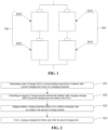
- the present inventors note that after the battery pack has been charged and discharged for a number of cycles, when the battery pack is charged again, there will be mutual charging between the various battery branches in the battery pack after the charging is completed, that is, one battery branch charges another battery branch. This is because there is an impedance mismatch between the battery branches in the battery pack, especially after the aging of battery cells in the battery branches, the impedance mismatch between the battery branches is more significant. At the end of the charging of the battery pack, there will be a situation where the overall state of charge (SOC) of one battery branch is higher than the overall SOC of another battery branch.
- SOC state of charge
- the battery aging parameter needs to be corrected in the charging control this time.
- the SOC of the battery is not easy to acquire directly, while the open-circuit voltage of the battery is easy to acquire, that is, the open-circuit voltage of the battery can be measured by the voltage measurement instrument.
- the open-circuit voltage of the target battery cell after mutual charging is less than the warning voltage value, which indicates that the target battery cell will not have the problem of overcharging after charging is stopped at this time and mutual charging occurs, then it is determined that the charge-receiving battery is not in the critical overcharge state. If the open-circuit voltage of the target battery cell after mutual charging is equal to the warning voltage value, which indicates that the target battery cell will not have the problem of overcharging after charging is stopped at this time and mutual charging occurs, but if charging continues at the next moment, the target battery cell will be overcharged after charging is stopped and mutual charging occurs, then it is determined that the charge-receiving battery has just reached the critical overcharge state.
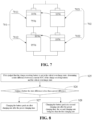
- FIG. 7 is a schematic diagram of the SOCs of battery cells in batteries after mutual charging in an embodiment of the present application.
- a first battery 701 is connected in parallel with a second battery 702.
- a first battery cell 7011 is connected in series with a second battery cell 7012.
- a third battery cell 7021 is connected in series with a fourth battery cell 7022. It is assumed that the first battery 701 transfers 20% of the amount of charge thereof to the second battery 702 (10% from each of the first battery cell 7011 and the second battery cell 7012, respectively).
- the SOC of the third battery cell 7021 is 95% and the SOC of the fourth battery cell 7022 is 75%.
- the fourth battery cell 7022 receives 10% of the amount of charge transfer, and when added to the original SOC of 75%, the SOC of the fourth battery cell 7022 is 85%, and the corresponding open-circuit voltage does not exceed the warning voltage value.
- the third battery cell 7021 receives 10% of the amount of charge transfer, and when added to the original SOC of 95%, the SOC of the third battery cell 7021 is 105%, and the corresponding open-circuit voltage has reached the warning voltage value, then at this time it is necessary to control to stop charging the battery pack. In this way, after charging is stopped and mutual charging is conducted, the battery pack reaches the maximum state of charge and the charge-receiving battery will not be overcharged.
- the battery aging parameter is still considered during the transfer of charge to the target battery cell, that is, the actual amount of charge received by the target battery cell is taken into account, which makes it possible to improve the accuracy of determining the open-circuit voltage of the target battery cell after mutual charging and thus more accurately determine whether the charge-receiving battery is in the critical overcharge state, thereby improving the accuracy of charging control of the battery pack.
- the battery pack needs to be charged at the smaller second charging rate after the preset charging time.
- the first charging rate may be the normal charging rate, i.e., 100%, or the fast charging rate, i.e. greater than 100%.
- the second charging rate is a low charging rate, i.e., less than 100%. The specific values of the first charging rate and the second charging rate are not limited herein.
- FIG. 9 is schematic structural diagram I of a charging control apparatus for a battery pack in an embodiment of the present application.
- the apparatus may include:
- FIG. 10 is schematic structural diagram II of a charging control apparatus for a battery pack in an embodiment of the present application.
- the apparatus may include:
- a determination module 1002 for determining SOCs corresponding respectively to the batteries after a preset charging time based on a charging parameter.
- FIG. 11 is a schematic structural diagram of an electronic device in an embodiment of the present application.
- this electronic device may include: a processor 1101, a memory 1102, and a bus 1103, wherein the processor 1101 and the memory 1102 complete communication with each other via the bus 1103; and the processor 1101 is used for invoking program instructions in the memory 1102 to perform the method in the above one or more embodiments.
Landscapes
- Engineering & Computer Science (AREA)
- Power Engineering (AREA)
- Physics & Mathematics (AREA)
- General Physics & Mathematics (AREA)
- Manufacturing & Machinery (AREA)
- Chemical & Material Sciences (AREA)
- Chemical Kinetics & Catalysis (AREA)
- Electrochemistry (AREA)
- General Chemical & Material Sciences (AREA)
- Charge And Discharge Circuits For Batteries Or The Like (AREA)
- Secondary Cells (AREA)
Applications Claiming Priority (2)
| Application Number | Priority Date | Filing Date | Title |
|---|---|---|---|
| CN202122624049 | 2021-10-29 | ||
| PCT/CN2022/096956 WO2023071197A1 (fr) | 2021-10-29 | 2022-06-02 | Procédé et appareil de commande de charge de bloc-batterie, dispositif électronique et support de stockage |
Publications (2)
| Publication Number | Publication Date |
|---|---|
| EP4199302A1 true EP4199302A1 (fr) | 2023-06-21 |
| EP4199302A4 EP4199302A4 (fr) | 2023-06-21 |
Family
ID=86146165
Family Applications (1)
| Application Number | Title | Priority Date | Filing Date |
|---|---|---|---|
| EP22746936.8A Pending EP4199302A4 (fr) | 2021-10-29 | 2022-06-02 | Procédé et appareil de commande de charge de bloc-batterie, dispositif électronique et support de stockage |
Country Status (4)
| Country | Link |
|---|---|
| US (1) | US12481000B2 (fr) |
| EP (1) | EP4199302A4 (fr) |
| JP (1) | JP7584524B2 (fr) |
| KR (1) | KR102809902B1 (fr) |
Families Citing this family (9)
| Publication number | Priority date | Publication date | Assignee | Title |
|---|---|---|---|---|
| EP4231483A4 (fr) * | 2021-09-08 | 2024-04-10 | Contemporary Amperex Technology Co., Limited | Procédé de charge de batterie d'alimentation et système de gestion de batterie |
| KR20260039811A (ko) | 2022-11-14 | 2026-03-20 | 아처 에비에이션 인크. | 고전압 배터리 아키텍처 |
| CN116315207B (zh) * | 2023-05-18 | 2023-11-03 | 宁德时代新能源科技股份有限公司 | 过压预警方法、装置和可读存储介质 |
| US20250033510A1 (en) * | 2023-07-27 | 2025-01-30 | GM Global Technology Operations LLC | Charging control system for a vehicle |
| US12330524B2 (en) | 2023-10-16 | 2025-06-17 | Archer Aviation, Inc. | Systems and methods for high voltage battery charging and vertiport operations |
| CN117783892B (zh) * | 2023-12-13 | 2024-08-27 | 深圳市韩特储能技术有限公司 | 一种基于分布式架构的电量计算方法及bms电池管理系统 |
| CN118428511A (zh) * | 2024-03-22 | 2024-08-02 | 北京海博思创科技股份有限公司 | 储能系统优化方法、装置、设备、存储介质和程序产品 |
| CN118376928B (zh) * | 2024-06-21 | 2024-09-03 | 杭州德海艾科能源科技有限公司 | 一种用于液流电池储能系统电站soc检测装置及计算方法 |
| CN118508574B (zh) * | 2024-07-17 | 2024-09-20 | 深圳安培时代数字能源科技有限公司 | 基于soc的电池管理方法及相关装置 |
Family Cites Families (22)
| Publication number | Priority date | Publication date | Assignee | Title |
|---|---|---|---|---|
| JP3890168B2 (ja) | 1999-08-03 | 2007-03-07 | 株式会社東京アールアンドデー | 電動装置及びその電池ユニットの充放電方法 |
| JP3696101B2 (ja) * | 2001-02-06 | 2005-09-14 | 三洋電機株式会社 | 充電方法と充電器 |
| JP4572850B2 (ja) | 2006-03-24 | 2010-11-04 | 株式会社日立製作所 | 電源制御装置 |
| KR101164629B1 (ko) | 2007-10-16 | 2012-07-11 | 한국과학기술원 | 직렬 연결 배터리 스트링을 위한 2단 전하 균일 방법 및장치 |
| JP5529402B2 (ja) | 2008-08-13 | 2014-06-25 | 三菱重工業株式会社 | 蓄電システム |
| JP5738519B2 (ja) | 2009-03-27 | 2015-06-24 | 伊藤忠商事株式会社 | 電池制御装置、車両、及び電池制御方法 |
| WO2012101771A1 (fr) | 2011-01-26 | 2012-08-02 | 株式会社 日立製作所 | Système de batterie de véhicule électrique |
| WO2012157747A1 (fr) | 2011-05-18 | 2012-11-22 | 古河電気工業株式会社 | Procédé de commande d'ensemble de batterie et dispositif de commande |
| FI123467B (fi) | 2011-07-08 | 2013-05-31 | Europ Batteries Oy | Menetelmä ja järjestelmä litium-ioni-kennoston varaustilan hallinnoimiseksi |
| JP2015012625A (ja) | 2013-06-26 | 2015-01-19 | 日東電工株式会社 | 電動・電熱機器用電源装置 |
| CN104426180B (zh) | 2013-08-28 | 2016-10-05 | 国家电网公司 | 一种均衡控制芯片和均衡控制方法 |
| JP2015115980A (ja) | 2013-12-09 | 2015-06-22 | 株式会社豊田自動織機 | 電圧均等化装置および電圧均等化方法 |
| CN103825336A (zh) | 2014-03-10 | 2014-05-28 | 上海锐奇工具股份有限公司 | 电池包充电方法 |
| JP2015195653A (ja) | 2014-03-31 | 2015-11-05 | Fdk株式会社 | 電池システム、充放電制御プログラム、充放電制御方法 |
| JP6548387B2 (ja) * | 2014-12-15 | 2019-07-24 | 川崎重工業株式会社 | 二次電池の充電状態推定方法および推定装置 |
| CN108736524A (zh) | 2017-04-17 | 2018-11-02 | 马岱瑶 | 一种可以蓄电、自发电、自充电独立的供电系统工艺技术 |
| JP6822300B2 (ja) | 2017-04-27 | 2021-01-27 | トヨタ自動車株式会社 | 充電率推定方法および車載の電池システム |
| EP3675200B1 (fr) * | 2017-08-25 | 2023-07-05 | Positec Power Tools (Suzhou) Co., Ltd | Outil électrique et procédé d'alimentation en énergie d'un outil électrique |
| JP7167581B2 (ja) * | 2018-09-19 | 2022-11-09 | 株式会社デンソー | 二次電池装置 |
| CN110783655B (zh) | 2019-11-05 | 2021-08-20 | 武汉纺织大学 | 一种带负脉冲放电的快速脉冲充电方法 |
| CN111725864B (zh) | 2020-06-02 | 2022-06-24 | 维沃移动通信有限公司 | 电量转移方法、电子设备及可读存储介质 |
| CN112721732B (zh) * | 2021-01-21 | 2022-05-24 | 重庆金康动力新能源有限公司 | 一种充电控制方法及相关设备 |
-
2022
- 2022-06-02 KR KR1020227028355A patent/KR102809902B1/ko active Active
- 2022-06-02 EP EP22746936.8A patent/EP4199302A4/fr active Pending
- 2022-06-02 JP JP2022548812A patent/JP7584524B2/ja active Active
- 2022-12-08 US US18/063,358 patent/US12481000B2/en active Active
Also Published As
| Publication number | Publication date |
|---|---|
| US12481000B2 (en) | 2025-11-25 |
| US20230133875A1 (en) | 2023-05-04 |
| KR102809902B1 (ko) | 2025-05-19 |
| JP2023550859A (ja) | 2023-12-06 |
| KR20230062471A (ko) | 2023-05-09 |
| JP7584524B2 (ja) | 2024-11-15 |
| EP4199302A4 (fr) | 2023-06-21 |
Similar Documents
| Publication | Publication Date | Title |
|---|---|---|
| EP4199302A1 (fr) | Procédé et appareil de commande de charge de bloc-batterie, dispositif électronique et support de stockage | |
| US10944273B2 (en) | Apparatus and method for balancing battery and battery pack including the same | |
| EP4152022B1 (fr) | Procédé de détermination de la capacité de pleine charge d'une batterie, procédé de détermination de l'état de santé d'une batterie, système et appareil | |
| JP5106272B2 (ja) | 劣化判定回路、電源装置、及び二次電池の劣化判定方法 | |
| EP3842816B1 (fr) | Procédé d'estimation d'état de charge de bloc-batterie | |
| CN115833290B (zh) | 电池包的充电控制方法、装置、电子设备及存储介质 | |
| US9400313B2 (en) | Method and device for determining the actual capacity of a battery | |
| CN102428379A (zh) | 蓄电设备的状态检测方法及其装置 | |
| JP2010098866A (ja) | 不均衡判定回路、不均衡低減回路、電池電源装置、及び不均衡判定方法 | |
| CN117769655A (zh) | 低压电池的状态校准方法及装置、电动车辆 | |
| EP4239348A1 (fr) | Appareil et procédé permettant d'estimer une capacité de cellule de batterie | |
| KR102948257B1 (ko) | 배터리 진단 장치 및 방법 | |
| CN116754980B (zh) | 确定电池soh值的方法、装置、用电装置及存储介质 | |
| KR102793739B1 (ko) | 배터리 관리 장치 및 방법 | |
| CN121142348B (zh) | 电池容量计算方法、ocv曲线修正方法、设备、介质及产品 | |
| EP4726410A1 (fr) | Dispositif et procédé de diagnostic de batterie | |
| US12584966B2 (en) | Apparatus and method for managing battery | |
| EP4597133A1 (fr) | Appareil et procédé de diagnostic de batterie | |
| KR102884998B1 (ko) | 배터리 진단 장치 및 방법 | |
| EP4700406A1 (fr) | Appareil et procédé de diagnostic de batterie | |
| KR102830331B1 (ko) | Soh 추정 장치 및 방법 | |
| EP4733788A1 (fr) | Appareil et procédé de gestion de batterie | |
| EP4481417A1 (fr) | Procédé de diagnostic de batterie et système de batterie destiné à fournir le procédé | |
| CN120993205A (zh) | 电池状态预测方法、装置、电子设备、存储介质及产品 | |
| KR20250171767A (ko) | 배터리 진단 장치 및 방법 |
Legal Events
| Date | Code | Title | Description |
|---|---|---|---|
| STAA | Information on the status of an ep patent application or granted ep patent |
Free format text: STATUS: UNKNOWN |
|
| STAA | Information on the status of an ep patent application or granted ep patent |
Free format text: STATUS: THE INTERNATIONAL PUBLICATION HAS BEEN MADE |
|
| PUAI | Public reference made under article 153(3) epc to a published international application that has entered the european phase |
Free format text: ORIGINAL CODE: 0009012 |
|
| STAA | Information on the status of an ep patent application or granted ep patent |
Free format text: STATUS: REQUEST FOR EXAMINATION WAS MADE |
|
| 17P | Request for examination filed |
Effective date: 20220808 |
|
| A4 | Supplementary search report drawn up and despatched |
Effective date: 20230127 |
|
| AK | Designated contracting states |
Kind code of ref document: A1 Designated state(s): AL AT BE BG CH CY CZ DE DK EE ES FI FR GB GR HR HU IE IS IT LI LT LU LV MC MK MT NL NO PL PT RO RS SE SI SK SM TR |
|
| RAP1 | Party data changed (applicant data changed or rights of an application transferred) |
Owner name: CONTEMPORARY AMPEREX TECHNOLOGY(HONG KONG) LIMITED |
|
| DAV | Request for validation of the european patent (deleted) | ||
| DAX | Request for extension of the european patent (deleted) |