EP4199318A1 - Wärmetauscher eines elektrischen moduls - Google Patents
Wärmetauscher eines elektrischen moduls Download PDFInfo
- Publication number
- EP4199318A1 EP4199318A1 EP21215730.9A EP21215730A EP4199318A1 EP 4199318 A1 EP4199318 A1 EP 4199318A1 EP 21215730 A EP21215730 A EP 21215730A EP 4199318 A1 EP4199318 A1 EP 4199318A1
- Authority
- EP
- European Patent Office
- Prior art keywords
- channel
- heat exchanger
- tubes
- housing
- channels
- Prior art date
- Legal status (The legal status is an assumption and is not a legal conclusion. Google has not performed a legal analysis and makes no representation as to the accuracy of the status listed.)
- Withdrawn
Links
Images



Classifications
-
- F—MECHANICAL ENGINEERING; LIGHTING; HEATING; WEAPONS; BLASTING
- F28—HEAT EXCHANGE IN GENERAL
- F28D—HEAT-EXCHANGE APPARATUS, NOT PROVIDED FOR IN ANOTHER SUBCLASS, IN WHICH THE HEAT-EXCHANGE MEDIA DO NOT COME INTO DIRECT CONTACT
- F28D7/00—Heat-exchange apparatus having stationary tubular conduit assemblies for both heat-exchange media, the media being in contact with different sides of a conduit wall
- F28D7/10—Heat-exchange apparatus having stationary tubular conduit assemblies for both heat-exchange media, the media being in contact with different sides of a conduit wall the conduits being arranged one within the other, e.g. concentrically
- F28D7/14—Heat-exchange apparatus having stationary tubular conduit assemblies for both heat-exchange media, the media being in contact with different sides of a conduit wall the conduits being arranged one within the other, e.g. concentrically both tubes being bent
-
- B—PERFORMING OPERATIONS; TRANSPORTING
- B60—VEHICLES IN GENERAL
- B60K—ARRANGEMENT OR MOUNTING OF PROPULSION UNITS OR OF TRANSMISSIONS IN VEHICLES; ARRANGEMENT OR MOUNTING OF PLURAL DIVERSE PRIME-MOVERS IN VEHICLES; AUXILIARY DRIVES FOR VEHICLES; INSTRUMENTATION OR DASHBOARDS FOR VEHICLES; ARRANGEMENTS IN CONNECTION WITH COOLING, AIR INTAKE, GAS EXHAUST OR FUEL SUPPLY OF PROPULSION UNITS IN VEHICLES
- B60K11/00—Arrangement in connection with cooling of propulsion units
- B60K11/02—Arrangement in connection with cooling of propulsion units with liquid cooling
-
- F—MECHANICAL ENGINEERING; LIGHTING; HEATING; WEAPONS; BLASTING
- F28—HEAT EXCHANGE IN GENERAL
- F28D—HEAT-EXCHANGE APPARATUS, NOT PROVIDED FOR IN ANOTHER SUBCLASS, IN WHICH THE HEAT-EXCHANGE MEDIA DO NOT COME INTO DIRECT CONTACT
- F28D7/00—Heat-exchange apparatus having stationary tubular conduit assemblies for both heat-exchange media, the media being in contact with different sides of a conduit wall
- F28D7/04—Heat-exchange apparatus having stationary tubular conduit assemblies for both heat-exchange media, the media being in contact with different sides of a conduit wall the conduits being spirally coiled
-
- F—MECHANICAL ENGINEERING; LIGHTING; HEATING; WEAPONS; BLASTING
- F28—HEAT EXCHANGE IN GENERAL
- F28D—HEAT-EXCHANGE APPARATUS, NOT PROVIDED FOR IN ANOTHER SUBCLASS, IN WHICH THE HEAT-EXCHANGE MEDIA DO NOT COME INTO DIRECT CONTACT
- F28D7/00—Heat-exchange apparatus having stationary tubular conduit assemblies for both heat-exchange media, the media being in contact with different sides of a conduit wall
- F28D7/08—Heat-exchange apparatus having stationary tubular conduit assemblies for both heat-exchange media, the media being in contact with different sides of a conduit wall the conduits being otherwise bent, e.g. in a serpentine or zig-zag
- F28D7/082—Heat-exchange apparatus having stationary tubular conduit assemblies for both heat-exchange media, the media being in contact with different sides of a conduit wall the conduits being otherwise bent, e.g. in a serpentine or zig-zag with serpentine or zig-zag configuration
- F28D7/085—Heat-exchange apparatus having stationary tubular conduit assemblies for both heat-exchange media, the media being in contact with different sides of a conduit wall the conduits being otherwise bent, e.g. in a serpentine or zig-zag with serpentine or zig-zag configuration in the form of parallel conduits coupled by bent portions
- F28D7/087—Heat-exchange apparatus having stationary tubular conduit assemblies for both heat-exchange media, the media being in contact with different sides of a conduit wall the conduits being otherwise bent, e.g. in a serpentine or zig-zag with serpentine or zig-zag configuration in the form of parallel conduits coupled by bent portions assembled in arrays, each array being arranged in the same plane
-
- F—MECHANICAL ENGINEERING; LIGHTING; HEATING; WEAPONS; BLASTING
- F28—HEAT EXCHANGE IN GENERAL
- F28D—HEAT-EXCHANGE APPARATUS, NOT PROVIDED FOR IN ANOTHER SUBCLASS, IN WHICH THE HEAT-EXCHANGE MEDIA DO NOT COME INTO DIRECT CONTACT
- F28D7/00—Heat-exchange apparatus having stationary tubular conduit assemblies for both heat-exchange media, the media being in contact with different sides of a conduit wall
- F28D7/10—Heat-exchange apparatus having stationary tubular conduit assemblies for both heat-exchange media, the media being in contact with different sides of a conduit wall the conduits being arranged one within the other, e.g. concentrically
- F28D7/106—Heat-exchange apparatus having stationary tubular conduit assemblies for both heat-exchange media, the media being in contact with different sides of a conduit wall the conduits being arranged one within the other, e.g. concentrically consisting of two coaxial conduits or modules of two coaxial conduits
-
- H—ELECTRICITY
- H05—ELECTRIC TECHNIQUES NOT OTHERWISE PROVIDED FOR
- H05K—PRINTED CIRCUITS; CASINGS OR CONSTRUCTIONAL DETAILS OF ELECTRIC APPARATUS; MANUFACTURE OF ASSEMBLAGES OF ELECTRICAL COMPONENTS
- H05K7/00—Constructional details common to different types of electric apparatus
- H05K7/20—Modifications to facilitate cooling, ventilating, or heating
- H05K7/20845—Modifications to facilitate cooling, ventilating, or heating for automotive electronic casings
- H05K7/20872—Liquid coolant without phase change
-
- B—PERFORMING OPERATIONS; TRANSPORTING
- B60—VEHICLES IN GENERAL
- B60K—ARRANGEMENT OR MOUNTING OF PROPULSION UNITS OR OF TRANSMISSIONS IN VEHICLES; ARRANGEMENT OR MOUNTING OF PLURAL DIVERSE PRIME-MOVERS IN VEHICLES; AUXILIARY DRIVES FOR VEHICLES; INSTRUMENTATION OR DASHBOARDS FOR VEHICLES; ARRANGEMENTS IN CONNECTION WITH COOLING, AIR INTAKE, GAS EXHAUST OR FUEL SUPPLY OF PROPULSION UNITS IN VEHICLES
- B60K1/00—Arrangement or mounting of electrical propulsion units
- B60K2001/003—Arrangement or mounting of electrical propulsion units with means for cooling the electrical propulsion units
-
- B—PERFORMING OPERATIONS; TRANSPORTING
- B60—VEHICLES IN GENERAL
- B60K—ARRANGEMENT OR MOUNTING OF PROPULSION UNITS OR OF TRANSMISSIONS IN VEHICLES; ARRANGEMENT OR MOUNTING OF PLURAL DIVERSE PRIME-MOVERS IN VEHICLES; AUXILIARY DRIVES FOR VEHICLES; INSTRUMENTATION OR DASHBOARDS FOR VEHICLES; ARRANGEMENTS IN CONNECTION WITH COOLING, AIR INTAKE, GAS EXHAUST OR FUEL SUPPLY OF PROPULSION UNITS IN VEHICLES
- B60K1/00—Arrangement or mounting of electrical propulsion units
- B60K2001/003—Arrangement or mounting of electrical propulsion units with means for cooling the electrical propulsion units
- B60K2001/005—Arrangement or mounting of electrical propulsion units with means for cooling the electrical propulsion units the electric storage means
-
- B—PERFORMING OPERATIONS; TRANSPORTING
- B60—VEHICLES IN GENERAL
- B60K—ARRANGEMENT OR MOUNTING OF PROPULSION UNITS OR OF TRANSMISSIONS IN VEHICLES; ARRANGEMENT OR MOUNTING OF PLURAL DIVERSE PRIME-MOVERS IN VEHICLES; AUXILIARY DRIVES FOR VEHICLES; INSTRUMENTATION OR DASHBOARDS FOR VEHICLES; ARRANGEMENTS IN CONNECTION WITH COOLING, AIR INTAKE, GAS EXHAUST OR FUEL SUPPLY OF PROPULSION UNITS IN VEHICLES
- B60K1/00—Arrangement or mounting of electrical propulsion units
- B60K2001/003—Arrangement or mounting of electrical propulsion units with means for cooling the electrical propulsion units
- B60K2001/006—Arrangement or mounting of electrical propulsion units with means for cooling the electrical propulsion units the electric motors
-
- B—PERFORMING OPERATIONS; TRANSPORTING
- B60—VEHICLES IN GENERAL
- B60L—PROPULSION OF ELECTRICALLY-PROPELLED VEHICLES; SUPPLYING ELECTRIC POWER FOR AUXILIARY EQUIPMENT OF ELECTRICALLY-PROPELLED VEHICLES; ELECTRODYNAMIC BRAKE SYSTEMS FOR VEHICLES IN GENERAL; MAGNETIC SUSPENSION OR LEVITATION FOR VEHICLES; MONITORING OPERATING VARIABLES OF ELECTRICALLY-PROPELLED VEHICLES; ELECTRIC SAFETY DEVICES FOR ELECTRICALLY-PROPELLED VEHICLES
- B60L2240/00—Control parameters of input or output; Target parameters
- B60L2240/40—Drive Train control parameters
- B60L2240/42—Drive Train control parameters related to electric machines
- B60L2240/425—Temperature
-
- B—PERFORMING OPERATIONS; TRANSPORTING
- B60—VEHICLES IN GENERAL
- B60L—PROPULSION OF ELECTRICALLY-PROPELLED VEHICLES; SUPPLYING ELECTRIC POWER FOR AUXILIARY EQUIPMENT OF ELECTRICALLY-PROPELLED VEHICLES; ELECTRODYNAMIC BRAKE SYSTEMS FOR VEHICLES IN GENERAL; MAGNETIC SUSPENSION OR LEVITATION FOR VEHICLES; MONITORING OPERATING VARIABLES OF ELECTRICALLY-PROPELLED VEHICLES; ELECTRIC SAFETY DEVICES FOR ELECTRICALLY-PROPELLED VEHICLES
- B60L2240/00—Control parameters of input or output; Target parameters
- B60L2240/40—Drive Train control parameters
- B60L2240/52—Drive Train control parameters related to converters
- B60L2240/525—Temperature of converter or components thereof
-
- F—MECHANICAL ENGINEERING; LIGHTING; HEATING; WEAPONS; BLASTING
- F28—HEAT EXCHANGE IN GENERAL
- F28D—HEAT-EXCHANGE APPARATUS, NOT PROVIDED FOR IN ANOTHER SUBCLASS, IN WHICH THE HEAT-EXCHANGE MEDIA DO NOT COME INTO DIRECT CONTACT
- F28D21/00—Heat-exchange apparatus not covered by any of the groups F28D1/00 - F28D20/00
- F28D2021/0019—Other heat exchangers for particular applications; Heat exchange systems not otherwise provided for
- F28D2021/0028—Other heat exchangers for particular applications; Heat exchange systems not otherwise provided for for cooling heat generating elements, e.g. for cooling electronic components or electric devices
-
- F—MECHANICAL ENGINEERING; LIGHTING; HEATING; WEAPONS; BLASTING
- F28—HEAT EXCHANGE IN GENERAL
- F28D—HEAT-EXCHANGE APPARATUS, NOT PROVIDED FOR IN ANOTHER SUBCLASS, IN WHICH THE HEAT-EXCHANGE MEDIA DO NOT COME INTO DIRECT CONTACT
- F28D21/00—Heat-exchange apparatus not covered by any of the groups F28D1/00 - F28D20/00
- F28D2021/0019—Other heat exchangers for particular applications; Heat exchange systems not otherwise provided for
- F28D2021/004—Other heat exchangers for particular applications; Heat exchange systems not otherwise provided for for engine or machine cooling systems
-
- F—MECHANICAL ENGINEERING; LIGHTING; HEATING; WEAPONS; BLASTING
- F28—HEAT EXCHANGE IN GENERAL
- F28D—HEAT-EXCHANGE APPARATUS, NOT PROVIDED FOR IN ANOTHER SUBCLASS, IN WHICH THE HEAT-EXCHANGE MEDIA DO NOT COME INTO DIRECT CONTACT
- F28D21/00—Heat-exchange apparatus not covered by any of the groups F28D1/00 - F28D20/00
- F28D2021/0019—Other heat exchangers for particular applications; Heat exchange systems not otherwise provided for
- F28D2021/008—Other heat exchangers for particular applications; Heat exchange systems not otherwise provided for for vehicles
-
- F—MECHANICAL ENGINEERING; LIGHTING; HEATING; WEAPONS; BLASTING
- F28—HEAT EXCHANGE IN GENERAL
- F28D—HEAT-EXCHANGE APPARATUS, NOT PROVIDED FOR IN ANOTHER SUBCLASS, IN WHICH THE HEAT-EXCHANGE MEDIA DO NOT COME INTO DIRECT CONTACT
- F28D21/00—Heat-exchange apparatus not covered by any of the groups F28D1/00 - F28D20/00
- F28D2021/0019—Other heat exchangers for particular applications; Heat exchange systems not otherwise provided for
- F28D2021/008—Other heat exchangers for particular applications; Heat exchange systems not otherwise provided for for vehicles
- F28D2021/0089—Oil coolers
-
- F—MECHANICAL ENGINEERING; LIGHTING; HEATING; WEAPONS; BLASTING
- F28—HEAT EXCHANGE IN GENERAL
- F28D—HEAT-EXCHANGE APPARATUS, NOT PROVIDED FOR IN ANOTHER SUBCLASS, IN WHICH THE HEAT-EXCHANGE MEDIA DO NOT COME INTO DIRECT CONTACT
- F28D21/00—Heat-exchange apparatus not covered by any of the groups F28D1/00 - F28D20/00
- F28D2021/0019—Other heat exchangers for particular applications; Heat exchange systems not otherwise provided for
- F28D2021/008—Other heat exchangers for particular applications; Heat exchange systems not otherwise provided for for vehicles
- F28D2021/0091—Radiators
- F28D2021/0094—Radiators for recooling the engine coolant
Definitions
- the present invention concerns equipment for an automotive vehicle, such as an electric vehicle (EV) or a hybrid vehicle (HV).
- EV electric vehicle
- HV hybrid vehicle
- the present invention relates, in particular, to a heat exchanger configured to efficiently dissipate heat generated by an electric module of an automotive vehicle.
- An electric module of an electric vehicle or a hybrid vehicle such as an electric drive, comprises devices such as a motor, a gearbox and an inverter, etc.
- the devices and components During operation of the electric module, the devices and components generate heat and must be cooled to be operational. Efficient cooling of the electric module makes it possible to increase the service life of the electric module. Therefore, the electric module comprises a cooling system for dissipating the heat generated by the devices and components of the electric module.
- the cooling system comprises, a first cooling circuit configured to dissipate the heat generated by the motor and the gearbox, and a second cooling circuit configured to dissipate the heat generated by the inverter.
- the first cooling circuit is an oil cooling circuit and the second cooling circuit is a water cooling circuit.
- the cooling system comprises further a heat exchanger located between the first and the second cooling circuits.
- a heat exchanger located between the first and the second cooling circuits.
- the present invention concerns a heat exchanger configured to dissipate heat generated by an electric module of an automobile vehicle.
- the heat exchanger comprises a housing, a first channel being formed in the housing and being configured to allow a first cooling medium to flow through, and a second channel which is formed in the housing and is configured to allow a second cooling medium to flow through, wherein the first channel is inserted into the second channel in a way that the first channel is surrounded by the second channel.
- the heat exchanger according to the present invention allows a better heat exchange efficiency so as to improve the heat dissipation of the electric module of the vehicle.
- the first channel is surrounded by different portions of the second channel, said different portions of the second channel being adjacent to the first channel.
- the first and the second channels are respectively a serpentine channel.
- the first and the second channels are respectively a spiral channel.
- the first channel comprises a first inlet configured to conduct the first cooling medium, and plural tubes which are parallel to each other and are connected to the first inlet, wherein the tubes are serpentine tubes or spiral tubes.
- the heat exchanger and a chamber defined by the housing of the heat exchanger are respectively in a shape of a cube or a rectangular cuboid, or, alternatively, in a shape of a cylinder.
- the tubes of the first channel are immersed into the flowing second cooling medium in the second channel.
- the heat exchanger comprises one or plural compartment walls configured to define the second channel.
- the heat exchanger comprises plural compartment walls, each of which comprises two ends, and only one of the two ends is fixed to one of inner walls of the chamber of the housing.
- the compartment walls comprise first and second compartment walls.
- the inner walls of the chamber of the housing comprise a first and a second inner walls which are opposite to each other.
- the first compartment walls are fixed to the first inner wall, and the second compartment walls are fixed to the second inner wall.
- the first and the second compartment walls are interlaced.
- the heat exchanger comprises a spiral-shaped compartment wall located in the chamber of the housing and between two parallel sides of the housing.
- the first channel comprises an inflow region comprising inflow portions, one of the inflow portions comprising the first inlet; the tubes being connected to the inflow portions of the inflow region, wherein compared to the inflow portions which are more distant from the first inlet, the inflow portions which are closer to the first inlet present respectively a greater inflow portion diameter so as to adjust the velocity profile inside the tubes.
- the tubes are serpentine tubes or spiral tubes.
- the tubes which are closer to the first inlet respectively present a greater inner diameter in order to adjust the velocity profile inside the tubes, wherein the tubes are serpentine tubes or spiral tubes.
- the one or plural compartment walls such as the first and the second compartment walls or the spiral-shaped compartment wall, are mounted into the housing, wherein the compartment walls and the housing are elements formed separately.
- the one or plural compartment walls are formed integrally with the housing by a casting process or by a milling process.
- the serpentine tubes or the spiral tubes are made of a material of high thermal conductivity.
- the first and the second channels are respectively a flat or a wavy serpentine channel or a flat spiral channel formed in the heat exchanger, the first and the second channels presenting each an elongated rectangular cross-section; the first channel being completely inserted into the second channel.
- the first and the second channels are respectively a flat serpentine tube mounted in a chamber defined by the housing; the widths of the flat serpentine tubes being both approximately equal to the width of the chamber defined by the housing.
- the first and the second channels are respectively a flat spiral tube mounted in a cylinder-shaped chamber defined by the housing; the widths of the flat spiral tubes being both approximately equal to the longitudinal length of the cylinder-shaped chamber defined by the housing.
- the first and the second channels are formed integrally with the housing so as to be embedded into the heat exchanger.
- the tube can be a wavy serpentine instead a flat serpentine.
- the first cooling medium flows through the first channel according to a first flow direction
- the second cooling medium flows through the second channel according to a second flow direction which is opposite to the first flow direction.
- the first and the second channels are formed throughout the whole volume of the heat exchanger.
- the present invention concerns an electric module comprising an electric motor, an inverter and a heat exchanger as described above.
- An electric module 100 of an automobile vehicle (e.g. an electric vehicle or a hybrid vehicle) comprises devices (e.g. an electric motor, an inverter, etc) which generate heat during operation, and a heat exchanger 50 configured to dissipate the generated heat.
- the heat exchanger 50 is located between an electric motor 102 and an inverter 103, as illustrated in Figures 1 and 2 .
- the heat exchanger 50 is in general located between a first cooling circuit of the motor 102 and of a gearbox and a second cooling circuit of the inverter 103.
- the first and the second cooling circuit are, for example, respectively an oil cooling circuit and a water cooling circuit.
- FIGS 3 to 7 illustrate the heat exchanger 50 according to a first embodiment of the invention
- Figures 10 to 12 illustrate the heat exchanger 50 according to a second embodiment of the invention
- Figures 11 to 13 illustrate the heat exchanger 50 according to a third embodiment of the invention
- Figures 14 to 17 illustrate the heat exchanger 50 according to a fourth embodiment of the invention.
- the heat exchanger 50 comprises a housing 51, a first channel 10 and a second channel 20.
- the housing 51 is preferably made of a metal material such as steel, aluminum or copper.
- the housing 51 is made of aluminum alloy or copper alloy.
- the first channel 10 and the second channel 20, respectively allowing a first cooling medium and a second cooling medium to flow through, are formed in a chamber defined by the housing 51 of the heat exchanger 50.
- the heat exchanger 50 and the chamber are respectively in a shape of a cube or a rectangular cuboid, as illustrated in Figures 1 to 10 of the first and the second embodiments of the invention.
- the heat exchanger 50 and the chamber are respectively in a shape of a cylinder, as illustrated in Figures 11 to 17 of the third and the fourth embodiments of the invention.
- the first and the second channels 10, 20 are respectively a serpentine channel, as described in the first and the second embodiments.
- the first and the second channels 10, 20 are respectively a spiral channel, as described in the third and the fourth embodiments which will be described more in detail after the description of the first and the second embodiments.
- the first channel 10 is inserted into the second channel 20 in a way that the first channel 10 is surrounded by the second channel 20. More precisely, the first channel 10 is surrounded by different portions of the second channel 20, said different portions being adjacent to the first channel 10. This allows thus a heat exchange between the first and the second channels 10, 20 occurs through channel walls of the first and the second channels 10, 20 as well as through the first and the second cooling media.
- the first and the second channels 10 and 20 are preferably formed throughout the whole volume of the heat exchanger 50.
- the first channel 10 comprises a first inlet 11 and a first outlet 12 which are respectively configured to conduct and to discharge the first cooling medium.
- the first inlet 11 and the first outlet 12 can be switched if needed.
- the first cooling medium flows through the first channel 10 according to a first flow direction 31.
- the first cooling medium is a thermal fluid, and is preferably oil, water, glycol or a glycol-water mixture.
- the second channel 20 comprises a second inlet 21 and a second outlet 22 which are respectively configured to conduct and to discharge a second cooling medium.
- the second inlet 21 and the second outlet 22 can be switched if needed.
- the second channel 20 allows the second cooling medium to flow through according to a second flow direction 32.
- the second cooling medium is a thermal fluid, and is preferably water, a glycol-water mixture, a glycol or oil.
- the second cooling medium can be identical or different from the first cooling medium.
- the second flow direction 32 can be opposite to the first flow direction 31, as depicted in the first and the second embodiments illustrated in Figures 3 and 8 . According to an alternative embodiment (not illustrated in figures), the second flow direction 32 is parallel to the first flow direction 31. Especially, the second flow direction 32 may be same with the first flow direction 31.
- Figures 3 to 7 illustrate the heat exchanger 50 according to the first embodiment of the invention.
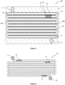
- Figure 3 illustrates a cross-sectional view of the heat exchanger 50.
- Figure 6 illustrates, according to a different perspective, the heat exchanger 50 without its housing 51.
- Figures 4 and 5 illustrate respectively the first channel 10 and the second channel 20 of the heat exchanger 50.
- Figure 7 illustrates an example in which the first channel 10 comprises an inflow region 71 comprising inflow portions with different inner diameters.
- the first and the second channels 10 and 20 are respectively a serpentine channel.
- the first channel 10 comprises the inflow region 71 comprising the first inlet 11, an outflow region 72 comprising the first outlet 12, and n tubes for decreasing a fluid pressure drop in the whole first channel 10, wherein "n" is a total number of the tubes.
- the tubes T1 to Tn are parallel to each other.
- a sum of outer diameters of the n tubes of the first channel 10 is approximately equal to the width of the chamber defined by the housing 51.
- the tubes of the first channel 10 are serpentine tubes.
- the first channel 10 comprises six parallel serpentine tubes T1, T2... to T6, and the number "n” is equal to 6.
- the invention is not limited to the number of the serpentine tubes utilized to form the first channel 10.
- the serpentine tubes are preferably made of a material of high thermal conductivity, such as copper or aluminum.
- the serpentine tubes present each a cross-section which can be round, square, or rectangular etc.
- the serpentine tubes T1 to T6 of the first channel 10 are circular tubes and their cross-sections are round.
- the invention is nevertheless limited to the shape of the cross-sections of the serpentine tubes.
- the serpentine tube Ti comprises one end being connected to the corresponding inflow portion which presents the inflow portion diameter Di, and the other end being connected to the outflow region 72, as depicted in Figure 7 .
- the first cooling medium flows, via the first inlet 11 and the inflow portions of the inflow region 71, into the serpentine tubes, and is then discharged from the outflow region 72 and the first outlet 12.
- the serpentine tube T1 is connected to the inflow portion which comprises the first inlet 11 and presents the inflow portion diameter D1.
- the inflow portion diameter D1 is equal to an inner diameter of the first inlet 11.
- the serpentine tube T6 is the most distant from the first inlet 11.
- the serpentine tube T2 is closer to the first inlet 11.
- the inflow portion diameter D1 to Dn of the inflow portions are equal to the inner diameter of the first inlet 11.
- the inflow portions which are closer to the first inlet 11 present respectively a greater inflow portion diameter Di, as represented in the following formula: D1 > D2 > ... > Dn.
- the inner diameter R1 to Rn of the serpentine tubes T1 to Tn are equal.
- tube walls of the serpentine tubes T1, T2... to Tn of the first channel 10 are respectively comprised preferably between 0.1 mm to 10 mm.
- the second channel 20 As for the second channel 20 according to the first embodiment, it is formed in a way to allow the first channel 10 to be inserted into the second channel 20, so that the serpentine tubes T1 to Tn of the first channel 10 are immersed into the flowing second cooling medium in the second channel 20.
- the heat exchanger comprises a plurality of compartment walls 53a, 53b configured to define the second channel 20.
- the compartment walls 53a, 53b are preferably made of a metal material such as steel, aluminum or copper.
- the compartment walls 53a, 53b is made of aluminum alloy or copper alloy.
- the compartment walls 53a, 53b are made of a polymer material.
- Each of the compartment walls 53a, 53b comprises two ends, and only one of the two ends is fixed to one of inner walls (e.g. 57a, 57b) of a chamber of the housing 51.
- the second channel 20 is defined by a first and a second inner walls 57a, 57b of the chamber of the housing 51, and the compartment walls comprising the first compartment walls 53a and the second compartment walls 53b.
- the first compartment walls 53a are fixed to the first inner wall 57a which is opposite to the second inner wall 57b.
- the second compartment walls 53b are fixed to the second inner wall 57b.
- the first and the second compartment walls 53a, 53b are interlaced.
- the first and the second compartment walls 53a, 53b and the housing 51 can be elements formed separately.
- the first and the second compartment walls 53a, 53b are mounted into the housing 51.
- the first and the second compartment walls 53a, 53b are formed integrally with the housing 51 by, for example, a casting process or a milling process.
- Figure 8 illustrates a cross-sectional view of the heat exchanger 50 according to the second embodiment of the invention.
- Figure 9 illustrates, according to a different perspective, the heat exchanger 50 without its housing 51 according to the second embodiment.
- Figure 10 illustrates the first channel 10 according to the second embodiment.
- the first and the second channels 10 and 20 are respectively a serpentine channel.
- the first and the second channels 10, 20 are respectively a flat serpentine channel formed in the heat exchanger 50.
- the first channel 10 is completely inserted into the second channel 20 in a way that the first channel 10 is surrounded by different portions of the second channel 20 which are adjacent to the first channel 10.
- the first channel 10 of the second embodiment is not directly immersed in the second cooling medium.
- the first and the second channels 10 and 20 present each an elongated rectangular cross-section.
- the widths W of the flat serpentine channels 10, 20 are both approximately equal to the width of the chamber defined by the housing 51.
- the first and the second channels 10, 20 are respectively a flat serpentine tube mounted in the chamber defined by the housing 51 of the heat exchanger 50.
- the flat serpentine tubes 10, 20 are preferably made of a material of high thermal conductivity, such as copper or aluminum.
- the widths (W) of the flat serpentine tubes 10, 20 are both approximately equal to the width of the chamber defined by the housing 51.
- the flat serpentine tubes 10, 20 and the housing 51 are elements formed separately.
- the first and the second channels 10, 20 can be formed integrally with the housing 51. In this way, the first and the second channels 10, 20 are embedded, without being mounted, into the heat exchanger 50.
- the width of the first channel 10 and that of the second channel 20 are both approximately equal to the width of the heat exchanger 50.
- the heat exchanger 50 allows thus a heat exchange between the first and the second channels 10, 20 to occur through channel walls of the first and the second channels 10, 20 and the first and the second cooling media.
- the heat exchanger 50 is located adjacent to the electric motor 102, as illustrated in Figures 11 and 14 .
- the electric motor 102 is in a shape of a cylinder, and rotates about a rotation axis which is also a central axis 111 of the heat exchanger 50.
- the heat exchanger 50 is attached to one of two ends of the electric motor 102.
- the heat exchanger 50 is, as mentioned above, in a shape of a cylinder presenting a longitudinal length 50L defined by a distance measured along with the central axis 111 and between two parallel sides of the heat exchanger 50.
- the heat exchanger 50 is preferably in a shape of a flat cylinder.
- the longitudinal length 50L of the heat exchanger 50 is smaller than that of the of the electric motor 102, and, for example, is greater than 1/6 and smaller than 1/2 of the longitudinal length of the electric motor 102.
- the first inlet 11 of the first channel 10 is preferably located on a peripheral wall of the housing 51.
- the second inlet 12 of the first channel 10 is preferably located close to or at the central axis 111 of the heat exchanger 50.
- the first inlet 11 and the first outlet 12 can be switched if needed.
- the second inlet 21 of the second channel 20 is preferably located close to or at the central axis 111 of the heat exchanger 50. In other words, the second inlet 21 may be located next to the first outlet 12.
- the second outlet 22 of the second channel 20 is preferably on the peripheral wall of the housing 51. The second inlet 21 and the second outlet 22 can be switched if needed.
- the first and the second channels 10, 20 in the third and fourth embodiments are respectively a spiral channel, as described in Figures 12 , 13 and 15 to 17.
- the spiral channels comprise respectively plural turns comprising a first turn, a last turn, and middle turns connected to the first turn and the last turn.
- the first turn is closest to the central axis 111 of the heat exchanger 50 while the last turn is the most distant from the central axis 111.
- the spiral channels 10, 20 are preferably formed throughout the whole volume of the heat exchanger 50.
- the width of the first channel 10 and that of the second channel 20 are both approximately equal to the longitudinal length 50L of the heat exchanger 50.
- the heat exchanger 50, the first channel 10 and the second channel 20 of the third embodiment of the invention are depicted respectively in Figures 11 to 13 .
- the first and the second channels 10, 20 are respectively a flat spiral channel formed in the heat exchanger 50.
- the flat spiral channel could have a rough wall or include additional structures .
- the first channel 10 is completely inserted into the second channel 20 in a way that the first channel 10 is surrounded by different portions of the second channel 20 which are adjacent to the first channel 10. Different from the four or the first embodiments, the first channel 10 of the third embodiment is not directly immersed in the second cooling medium.
- the first and the second channels 10 and 20 present each an elongated rectangular cross-section.
- the widths W of the flat spiral channels 10, 20 are both approximately equal to the longitudinal length of the cylinder-shaped chamber defined by the housing 51.
- the first and the second channels 10, 20 are respectively a flat spiral tube mounted in the cylinder-shaped chamber defined by the housing 51 of the heat exchanger 50.
- the flat spiral tubes 10, 20 are preferably made of a material of high thermal conductivity, such as copper or aluminum.
- the widths W of the flat spiral tubes 10, 20 are both approximately equal to the longitudinal length of the cylinder-shaped chamber.
- the flat spiral tubes 10, 20 and the housing 51 are elements formed separately.
- the first and the second channels 10, 20 can be formed integrally with the housing 51. In this way, the first and the second channels 10, 20 are embedded, without being mounted, into the heat exchanger 50.
- FIG. 14 illustrates the first channel 10.
- Figures 16 illustrates a spiral-shaped compartment wall 53c corresponding to the second channel 20.
- Figure 17 illustrates, according to a different perspective, the heat exchanger 50 without its housing 51.
- the fourth embodiment and the above-mentioned third embodiment are similar in a way that in both of these embodiments, the first channel 10 and the second channel 20 are respectively a spiral channel.
- the fourth embodiment and the above-mentioned first embodiment also present some similarities which will be described in the following paragraphs.
- the first channel 10 of the fourth embodiment being similar to the first channel 10 of the first embodiment, comprises the inflow region 71 comprising the first inlet 11, the outflow region 72 comprising the first outlet 12, and n tubes for decreasing a fluid pressure drop in the whole first channel 10, wherein "n" is a total number of the tubes.
- the tubes comprised in the first channel 10 of the first embodiment are serpentine tubes, while the tubes comprised in the first channel 10 of the fourth embodiment are spiral tubes, as illustrated in Figures 6 and 17 .
- the second channel 20 is formed in a way to allow the first channel 10 to be inserted into the second channel 20, so that the spiral tubes T1 to Tn of the first channel 10 are immersed into the flowing second cooling medium in the second channel 20.
- the spiral tubes T1 to Tn are parallel to each other.
- a sum of outer diameters of the n spiral tubes of the first channel 10 is approximately equal to the longitudinal length of the cylinder-shaped chamber defined by the housing 51.
- first channel 10 of the fourth embodiment comprises spiral tubes while the first channel 10 of the first embodiment comprises the above-mentioned serpentine tubes
- spiral tubes and serpentine tubes are similar in terms of the inner diameters Di of the inflow portions of the inflow region 71, the outflow region 72, the inner diameters Ri of the tubes Ti, as well as the material and the shape of the cross-sections of the tubes, etc.
- the second channel 20 is formed in a way to allow the first channel 10 to be inserted into the second channel 20, so that the spiral tubes of the first channel 10 are immersed into the flowing second cooling medium in the second channel 20.
- the heat exchanger comprises a spiral-shaped compartment wall 53c configured to define the second channel 20, as illustrated in Figure 16 .
- the spiral-shaped compartment wall 53c of the fourth embodiment is similar to the compartment walls 53a, 53b of the first embodiment in terms of the function and the material.
- the spiral-shaped compartment wall 53c is located in the chamber of the housing 51 and between the two parallel sides of the housing 51. Moreover, the width of the spiral-shaped compartment wall 53c is approximately equal to the longitudinal length of the chamber defined by the housing 51.
- the second channel 20 is thus defined by the two parallel sides of the cylinder-shaped chamber of the housing 51 and the spiral-shaped compartment wall 53c.
- the spiral-shaped compartment wall 53c and the housing 51 can be elements formed separately.
- the spiral-shaped compartment wall 53c are mounted into the housing 51.
- the spiral-shaped compartment wall 53c are formed integrally with the housing 51 by, for example, a casting process or a milling process.
- the second flow direction 32 can be opposite to the first flow direction 31, as depicted in Figures 12 and 13 .
- the second flow direction 32 is parallel to the first flow direction 31.
- the second flow direction 32 may be same with the first flow direction 31.
- the heat exchanger 50 allows a heat exchange between the first and the second channels 10, 20 to occur through channel walls of the first and the second channels 10, 20 and the first and the second cooling media.
- the heat exchanger according to the present invention allows thus to dissipate, for instance, 8 kW losses from a motor and a gearbox of an electric module, and to reduce the oil temperature of the motor from 110°C to 88°C.
- the heat exchange efficiency as well as the heat dissipation of the electric module are thus improved.
Landscapes
- Engineering & Computer Science (AREA)
- Physics & Mathematics (AREA)
- Thermal Sciences (AREA)
- Mechanical Engineering (AREA)
- General Engineering & Computer Science (AREA)
- Microelectronics & Electronic Packaging (AREA)
- Chemical & Material Sciences (AREA)
- Combustion & Propulsion (AREA)
- Transportation (AREA)
- Heat-Exchange Devices With Radiators And Conduit Assemblies (AREA)
Priority Applications (1)
| Application Number | Priority Date | Filing Date | Title |
|---|---|---|---|
| EP21215730.9A EP4199318A1 (de) | 2021-12-17 | 2021-12-17 | Wärmetauscher eines elektrischen moduls |
Applications Claiming Priority (1)
| Application Number | Priority Date | Filing Date | Title |
|---|---|---|---|
| EP21215730.9A EP4199318A1 (de) | 2021-12-17 | 2021-12-17 | Wärmetauscher eines elektrischen moduls |
Publications (1)
| Publication Number | Publication Date |
|---|---|
| EP4199318A1 true EP4199318A1 (de) | 2023-06-21 |
Family
ID=78957309
Family Applications (1)
| Application Number | Title | Priority Date | Filing Date |
|---|---|---|---|
| EP21215730.9A Withdrawn EP4199318A1 (de) | 2021-12-17 | 2021-12-17 | Wärmetauscher eines elektrischen moduls |
Country Status (1)
| Country | Link |
|---|---|
| EP (1) | EP4199318A1 (de) |
Citations (13)
| Publication number | Priority date | Publication date | Assignee | Title |
|---|---|---|---|---|
| JPH06123566A (ja) * | 1992-10-12 | 1994-05-06 | Orion Mach Co Ltd | 熱交換器及びその製作方法並びに圧縮空気除湿装置 |
| GB2413841A (en) * | 2004-05-07 | 2005-11-09 | Matthew Rutherford | A heat exchange unit utilising waste water to heat cold mains water |
| WO2007108240A1 (ja) * | 2006-03-16 | 2007-09-27 | Matsushita Electric Industrial Co., Ltd. | 熱交換器 |
| WO2011079483A1 (zh) * | 2009-12-31 | 2011-07-07 | 英特换热设备(浙江)有限公司 | 同轴换热器 |
| KR20120043916A (ko) * | 2010-10-27 | 2012-05-07 | 엘지전자 주식회사 | 열교환 장치 |
| WO2013105487A1 (ja) * | 2012-01-13 | 2013-07-18 | パナソニック株式会社 | 熱交換器 |
| KR20130104313A (ko) * | 2012-03-13 | 2013-09-25 | 주식회사 아성프라텍 | 이중관 열교환기를 채택한 전기 자동차용 히트 펌프 시스템 |
| JP2015028390A (ja) * | 2013-07-30 | 2015-02-12 | パナソニック株式会社 | 熱交換器 |
| CN104776486A (zh) * | 2014-07-15 | 2015-07-15 | 昆山昶乐模塑科技有限公司 | 一种储水式暖气热水器 |
| DE102016216430A1 (de) * | 2016-08-31 | 2018-03-01 | Hanon Systems | Abgaskühler sowie Verfahren und Montagewerkzeug zur Einbringung von Kühlrippen in einen Abgaskühler |
| WO2019160522A1 (en) * | 2018-02-14 | 2019-08-22 | Lashkul Oleksandr Anatoliyovych | Three-contour spiral heat exchanger |
| WO2019160521A1 (en) * | 2018-02-14 | 2019-08-22 | Lashkul Oleksandr Anatoliyovych | Spiral heat exchanger |
| EP3901537A1 (de) * | 2018-12-30 | 2021-10-27 | Zhejiang Jizhi New Energy Automobile Technology Co., Ltd | Integrierte kühlkörperanordnung |
-
2021
- 2021-12-17 EP EP21215730.9A patent/EP4199318A1/de not_active Withdrawn
Patent Citations (13)
| Publication number | Priority date | Publication date | Assignee | Title |
|---|---|---|---|---|
| JPH06123566A (ja) * | 1992-10-12 | 1994-05-06 | Orion Mach Co Ltd | 熱交換器及びその製作方法並びに圧縮空気除湿装置 |
| GB2413841A (en) * | 2004-05-07 | 2005-11-09 | Matthew Rutherford | A heat exchange unit utilising waste water to heat cold mains water |
| WO2007108240A1 (ja) * | 2006-03-16 | 2007-09-27 | Matsushita Electric Industrial Co., Ltd. | 熱交換器 |
| WO2011079483A1 (zh) * | 2009-12-31 | 2011-07-07 | 英特换热设备(浙江)有限公司 | 同轴换热器 |
| KR20120043916A (ko) * | 2010-10-27 | 2012-05-07 | 엘지전자 주식회사 | 열교환 장치 |
| WO2013105487A1 (ja) * | 2012-01-13 | 2013-07-18 | パナソニック株式会社 | 熱交換器 |
| KR20130104313A (ko) * | 2012-03-13 | 2013-09-25 | 주식회사 아성프라텍 | 이중관 열교환기를 채택한 전기 자동차용 히트 펌프 시스템 |
| JP2015028390A (ja) * | 2013-07-30 | 2015-02-12 | パナソニック株式会社 | 熱交換器 |
| CN104776486A (zh) * | 2014-07-15 | 2015-07-15 | 昆山昶乐模塑科技有限公司 | 一种储水式暖气热水器 |
| DE102016216430A1 (de) * | 2016-08-31 | 2018-03-01 | Hanon Systems | Abgaskühler sowie Verfahren und Montagewerkzeug zur Einbringung von Kühlrippen in einen Abgaskühler |
| WO2019160522A1 (en) * | 2018-02-14 | 2019-08-22 | Lashkul Oleksandr Anatoliyovych | Three-contour spiral heat exchanger |
| WO2019160521A1 (en) * | 2018-02-14 | 2019-08-22 | Lashkul Oleksandr Anatoliyovych | Spiral heat exchanger |
| EP3901537A1 (de) * | 2018-12-30 | 2021-10-27 | Zhejiang Jizhi New Energy Automobile Technology Co., Ltd | Integrierte kühlkörperanordnung |
Similar Documents
| Publication | Publication Date | Title |
|---|---|---|
| EP1956331A2 (de) | Wärmetauscher | |
| CN107864666B (zh) | 热交换器和用于电动或混合动力车辆的热管理装置 | |
| JP2008180486A (ja) | 熱交換器 | |
| WO1991019949A1 (en) | Tube and fin circular heat exchanger | |
| US8522862B2 (en) | Vehicle radiator | |
| KR102043931B1 (ko) | 열 전달 장치 | |
| US20090272516A1 (en) | Method of Determining a Size of a Heat Exchanger for a Vehicle | |
| CN105904960B (zh) | 冷却模块 | |
| EP2530271A2 (de) | Kombiniertes Wärmetauschersystem | |
| JP2006522311A (ja) | 乗物用のオイル・クーラー | |
| US6516873B1 (en) | Heat exchanger | |
| US5289873A (en) | Heat exchanger sideplate interlocked with header | |
| EP1804015A1 (de) | Wärmetauscher | |
| EP4199318A1 (de) | Wärmetauscher eines elektrischen moduls | |
| JP4607626B2 (ja) | 効率的な熱交換器、およびそれを用いたエンジン | |
| KR20130065174A (ko) | 차량용 열교환기 | |
| JP2005106329A (ja) | サブクールタイプコンデンサ | |
| EP4198432A1 (de) | Wärmetauscher eines elektrischen moduls | |
| JP2002372340A (ja) | 凝縮器 | |
| EP1962044A1 (de) | Verbesserter Wärmetauscher für ein Kraftfahrzeug | |
| JP2018146216A (ja) | 複数流路熱交換器 | |
| US12453043B2 (en) | Mechanically expanded microfin tube liquid cooled heat sink | |
| US20240410654A1 (en) | Heat exchanger assembly for a motor vehicle | |
| JP2012245865A (ja) | 複合熱交換器 | |
| JP2000220982A (ja) | 熱交換器 |
Legal Events
| Date | Code | Title | Description |
|---|---|---|---|
| PUAI | Public reference made under article 153(3) epc to a published international application that has entered the european phase |
Free format text: ORIGINAL CODE: 0009012 |
|
| STAA | Information on the status of an ep patent application or granted ep patent |
Free format text: STATUS: THE APPLICATION HAS BEEN PUBLISHED |
|
| AK | Designated contracting states |
Kind code of ref document: A1 Designated state(s): AL AT BE BG CH CY CZ DE DK EE ES FI FR GB GR HR HU IE IS IT LI LT LU LV MC MK MT NL NO PL PT RO RS SE SI SK SM TR |
|
| STAA | Information on the status of an ep patent application or granted ep patent |
Free format text: STATUS: REQUEST FOR EXAMINATION WAS MADE |
|
| 17P | Request for examination filed |
Effective date: 20231215 |
|
| RBV | Designated contracting states (corrected) |
Designated state(s): AL AT BE BG CH CY CZ DE DK EE ES FI FR GB GR HR HU IE IS IT LI LT LU LV MC MK MT NL NO PL PT RO RS SE SI SK SM TR |
|
| REG | Reference to a national code |
Ref country code: DE Ref legal event code: R079 Free format text: PREVIOUS MAIN CLASS: H02K0005200000 Ipc: F28D0007140000 |
|
| GRAP | Despatch of communication of intention to grant a patent |
Free format text: ORIGINAL CODE: EPIDOSNIGR1 |
|
| STAA | Information on the status of an ep patent application or granted ep patent |
Free format text: STATUS: GRANT OF PATENT IS INTENDED |
|
| RIC1 | Information provided on ipc code assigned before grant |
Ipc: F28D 21/00 20060101ALI20250417BHEP Ipc: H05K 7/20 20060101ALI20250417BHEP Ipc: B60K 11/02 20060101ALI20250417BHEP Ipc: F28D 7/08 20060101ALI20250417BHEP Ipc: F28D 7/04 20060101ALI20250417BHEP Ipc: F28D 7/10 20060101ALI20250417BHEP Ipc: F28D 7/14 20060101AFI20250417BHEP |
|
| INTG | Intention to grant announced |
Effective date: 20250509 |
|
| STAA | Information on the status of an ep patent application or granted ep patent |
Free format text: STATUS: THE APPLICATION IS DEEMED TO BE WITHDRAWN |
|
| 18D | Application deemed to be withdrawn |
Effective date: 20250910 |