EP4199384B1 - Procédé et appareil pour déterminer un décalage de fréquence d'horloge - Google Patents
Procédé et appareil pour déterminer un décalage de fréquence d'horloge Download PDFInfo
- Publication number
- EP4199384B1 EP4199384B1 EP21214375.4A EP21214375A EP4199384B1 EP 4199384 B1 EP4199384 B1 EP 4199384B1 EP 21214375 A EP21214375 A EP 21214375A EP 4199384 B1 EP4199384 B1 EP 4199384B1
- Authority
- EP
- European Patent Office
- Prior art keywords
- message
- clock
- time
- departure
- arrival
- Prior art date
- Legal status (The legal status is an assumption and is not a legal conclusion. Google has not performed a legal analysis and makes no representation as to the accuracy of the status listed.)
- Active
Links
Images


Classifications
-
- H—ELECTRICITY
- H04—ELECTRIC COMMUNICATION TECHNIQUE
- H04W—WIRELESS COMMUNICATION NETWORKS
- H04W56/00—Synchronisation arrangements
- H04W56/001—Synchronization between nodes
-
- H—ELECTRICITY
- H04—ELECTRIC COMMUNICATION TECHNIQUE
- H04J—MULTIPLEX COMMUNICATION
- H04J3/00—Time-division multiplex systems
- H04J3/02—Details
- H04J3/06—Synchronising arrangements
- H04J3/0635—Clock or time synchronisation in a network
- H04J3/0638—Clock or time synchronisation among nodes; Internode synchronisation
- H04J3/0658—Clock or time synchronisation among packet nodes
- H04J3/0661—Clock or time synchronisation among packet nodes using timestamps
- H04J3/0667—Bidirectional timestamps, e.g. NTP or PTP for compensation of clock drift and for compensation of propagation delays
-
- H—ELECTRICITY
- H04—ELECTRIC COMMUNICATION TECHNIQUE
- H04J—MULTIPLEX COMMUNICATION
- H04J3/00—Time-division multiplex systems
- H04J3/02—Details
- H04J3/06—Synchronising arrangements
- H04J3/0635—Clock or time synchronisation in a network
- H04J3/0638—Clock or time synchronisation among nodes; Internode synchronisation
- H04J3/0658—Clock or time synchronisation among packet nodes
- H04J3/0661—Clock or time synchronisation among packet nodes using timestamps
- H04J3/0664—Clock or time synchronisation among packet nodes using timestamps unidirectional timestamps
-
- H—ELECTRICITY
- H04—ELECTRIC COMMUNICATION TECHNIQUE
- H04W—WIRELESS COMMUNICATION NETWORKS
- H04W56/00—Synchronisation arrangements
- H04W56/0055—Synchronisation arrangements determining timing error of reception due to propagation delay
- H04W56/0065—Synchronisation arrangements determining timing error of reception due to propagation delay using measurement of signal travel time
Definitions
- This disclosure relates to a method and an apparatus for determining a clock frequency offset between a first device having a first clock and at least one second device having at least one second clock.
- the disclosure further relates to a corresponding system, a corresponding computer program product and a corresponding computer readable storage medium.
- timing related information between devices is an important issue. For example in order to synchronize a clock of a first device to a clock of a second device, the first device needs to obtain timing information regarding the clock of the second device. Such timing information may be related, for example, to a frequency and/or an offset of the clock of the second device with regard to the first device.
- EP 2749968 A1 discloses a time control device that can synchronize time information with a master device in a network with high precision.
- the time control device includes: a calculating unit that calculates a time difference from the master device and a network delay based on the transmission times and the reception times of messages exchanged with the master device, the network delay indicating the period of time required for communicating the messages via the network; a PID processing unit that generates a feedback control value f1 based on the calculated time difference, the feedback control value f1 being used for performing feedback control on time information about the slave device; a f0 generating unit that generates a feedback control value f0 based on the generated feedback control value f1; and an adjusting unit that adjusts the time information about the slave device in accordance with the feedback control value f1 or the feedback control value f0, whichever is selected based on the calculated network delay.
- US 10,911,211 B1 discloses a method, which includes, at a first node: transmitting a first calibration signal at a first time-of-departure measured by the first node; and transmitting a second calibration signal at a second time-of-departure measured by the first node.
- the method also includes, at a second node: receiving the first calibration signal at a first time-of-arrival measured by the second node; and receiving the second calibration signal at a second time-of-arrival measured by the second node.
- the method further includes: defining a first calibration point and a second calibration point in a set of calibration points, each calibration point comprising a time-of-departure and a time-of-arrival of each calibration signal; calculating a regression on the set of calibration points; and calculating a frequency offset between the first node and the second node based on the first regression.
- a method for determining a clock frequency offset between a first device having a first clock and at least one second device having at least one second clock comprises:
- An advantage of this method is that a clock frequency offset between different devices, each having its own free-running clock used for time measurements, may be determined based on only two messages, exchanged between the respective devices, and the corresponding times of departures/times of arrivals. This way, a determination of the frequency offset is achieved in an easy and resource saving manner, wherein only low overhead is produced.
- Another advantage of this method is that the clock frequency offset between the devices may be determined without knowledge regarding a distance between the respective devices.
- the messages exchanged between the devices may be furthermore used for any kind of communication between the devices.
- the method according to the first aspect may be implemented in devices exchanging any kind of communication messages, from which the corresponding times of departure may be obtained.
- no additional messages are needed in that case, and an overhead in a corresponding communication network may be reduced.
- a time of departure of a message defines a time at which the corresponding message is sent from a sending device.
- a time of arrival of a message defines the time at which the corresponding message is received at a receiving device.
- the clock frequency offset between clocks in this application defines the difference between frequencies of clocks, which is an indicator for how much slower/faster one clock runs compared to another clock.
- the clock frequency offset may be determined by the at least one second device itself, or may be determined by any other entity which, in that case, obtains the relevant information, i.e., the time of departure of the at least one first message, the time of arrival of the at least one first message, the time of departure of the at least one second message, and the time of arrival of the at least one second message.
- a clock phase offset may be determined based on only three messages, exchanged between the respective devices, and the corresponding times of departures/times of arrivals. This way, a determination of the phase offset is achieved in an easy and resource saving manner, wherein only low overhead is produced.
- Another advantage herein is that also the clock phase offset between the devices may be determined without knowledge regarding a distance between the respective devices.
- the clock phase offset may be determined by the at least one second device itself, or may be determined by any other entity which, in that case, obtains the relevant information, i.e., the time of arrival of the at least one first message, the time of departure of the at least one first message, the time of arrival of the at least one second message, the time of departure of the at least one second message, the time of departure of the at least one third message, and a time of arrival of the at least one third message.
- the information regarding the time of departure of the at least one first message and/or of the at least one second message and/or of the at least one third message is in the at least one first and/or second and/or third message embedded in form of a timestamp in the at least one first and/or second and/or third message or derivable from a predetermined scheduling of the at least one first and/or second and/or third message.
- An advantage of embedding the information regarding the time of departure in the respective messages in form of a timestamp is that no additional information, for example regarding a scheduling of messages, is required by the respective devices.
- An advantage of the information regarding the time of departure being in the respective messages in form of a predetermined scheduling of the respective messages and therefore being derivable from said predetermined scheduling is that no further information needs to be added to the transmitted messages in order to inform the receiving device of the time of departure of the received message, thereby further reducing overhead. For example, when certain messages are sent by a transmitting device at certain points in time, known to the receiving device, the receiving device immediately knows the time of departure when the respective message is received.
- the method further comprises the step: synchronizing the at least one second clock to the first clock based on the determined clock frequency offset and/or based on the determined clock phase offset, or synchronizing the first clock to the at least one second clock based on the determined clock frequency offset and/or based on the determined clock phase offset.
- Synchronizing the at least one second clock to the first clock based on the determined clock frequency offset may be done by adapting a clock frequency of the at least one second clock to a clock frequency of the first clock, i.e., minimizing the clock frequency offset between the respective clocks.
- Synchronizing the at least one second clock to the first clock based on the determined clock phase offset may be done by adapting a current time of the at least one second clock to the first clock, i.e., minimizing a timing offset between the respective clocks.
- the clock frequency offset and the timing offset between respective clocks may be minimized by synchronizing the respective clocks based on both the determined clock frequency offset and the determined clock phase offset.
- the first clock may be synchronized, analogously to the above, to the at least one second clock.
- the first clock may be synchronized, analogously to the above, to the at least one second clock.
- more than one second device, and correspondingly more than one second clock is present, this way, a synchronization of the first device to multiple second devices is made possible.
- An advantage herein is that a one-to-many synchronization is achieved in a resource saving and easy implementable manner.
- one of the corresponding second clocks may be synchronized to the first clock and/or to second clocks of the other second devices according to the above-described manner.
- the synchronizing of the at least one second or the first clock comprises offsetting timing values of the at least one second or the first clock.
- An advantage thereof is that an easy way of synchronizing the respective clocks is provided.
- synchronizing may be implemented in software, according to which timing values, such as for example certain timestamps generated by the respective device, are corrected based on the determined clock phase offset and/or the determined clock frequency offset.
- Clock synchronization may be performed based on clock model parameters, i.e. clock phase offset and clock frequency offset, rather than by physically steering the clock in this embodiment.
- the at least one second clock and/or the first clock are synchronized with respect to the other clocks of the at least two second clocks and/or the first clock based on a weighted zero mean error; or the at least one second clock and/or the first clock are synchronized to one of the other clocks of the at least two second clock and/or the first clock, which serves as a master clock.
- the other clocks of the at least two second clocks and/or the first clock in this context, describe the clocks, except the one which is to be synchronized.
- the other clocks in this case, are the second of the two second clocks and the first clock.
- all second clocks are the other clocks in this context.
- An advantage of the above embodiments is that an easily implementable possibility of synchronizing clocks of multiple devices is provided.
- By synchronizing clocks to a weighted zero mean error an average system time of multiple clocks comprised in such system is determined, to which single clocks then can be synchronized.
- This is advantageous in that for synchronizing the clocks, not only one single master clock needs to be trusted, and hence a more reliable synchronization is possible, for example in case such single master clock is erroneous or completely fails.
- clocks may be synchronized to one master clock.
- one device has a more reliable clock, it is advantageous to synchronize other clocks to that device's clock being used as master clock.
- one device has a clock that is being synchronized to another entity, such as, for example, a first device serving as a gateway between an indoor navigation system having multiple second devices and a global navigation satellite system (GNSS) satellite, it is possible to synchronize the first device to the GNSS satellite and then synchronize the second devices to the first device according to the above-described method, wherein the first device provides the master clock, to which each of the second devices may be synchronized.
- GNSS global navigation satellite system
- an apparatus comprises a processor, a receiver and a second clock, wherein:
- the apparatus further comprises a transmitter, wherein:
- the clock frequency offset and/or the clock phase offset is determined by the processor of the apparatus or by an external device.
- An advantage of determining the respective offsets by the processor of the apparatus is that overhead is kept low, since it is directly the apparatus itself which may determine those offsets.
- An advantage of determining the respective offsets by an external device is that processing resources of the apparatus are saved and, in particular in case multiple apparatuses like the one described above are present, a central entity may be used to determine the respective offsets for multiple apparatuses.
- the processor is further arranged to synchronize the second clock to the first clock based on the determined clock frequency offset and/or the determined clock phase offset by offsetting timing values of the second clock.
- a system comprises a first device and at least one apparatus according to the second aspect.
- a computer program product comprises instructions which, when executed on a computer, cause the computer to perform the method according to the first aspect.
- a computer readable storage medium comprises the computer program product according to the fourth aspect.
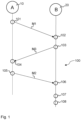
- Figure 1 shows a schematic flowchart of a method 100 for determining a clock frequency offset and a clock phase offset according to one embodiment of the disclosure.
- the flowchart of the method 100 shows messages being exchanged between a first device 10 and a second device 20 in order to determine a clock frequency offset and a clock phase offset between a first clock, not shown herein, of the first device 10 and a second clock, not shown herein, of the second device 20.
- the first device 10 sends a first message M1 to the second device 20.
- the first message M1 is sent by the first device 10 at a certain time instance, which is defined as the time of departure td 1 A of the first message M1 from the first device 10.
- the time of departure td 1 A is related to the first clock of the first device.
- the time of departure td 1 A of the first message M1 is in the first message M1.
- the time of departure td 1 A is embedded in form of a timestamp, included in and transmitted together with the first message M1, for example in a header of the first message M1.
- the time of departure td 1 A could be implicit in the first message M1, not in form of an explicit timestamp, but based on a scheduling of the first message, known to the second device 20, such that the second device 20 would know from the schedule, when receiving the first message M1, that the first message M1 was sent by the first device 10 at such certain time instance.
- the first message M1 is received by the second device 20.
- the first message M1 is received by the second device 20 at a certain time instance, which is defined as the time of arrival ta 1 B of the first message M1 at the second device 20.
- the second device 20 detects the time of arrival ta 1 B of the first message M1, which is measured by the second clock of the second device 20, and stores the time of arrival ta 1 B .
- the second device 20 further obtains the time of departure td 1 A of the first message M1 from the first message M1 and stores it.
- the second device 20 sends a third message M3 to the first device 10.
- the third message M3 is sent by the second device 20 at a certain time instance, which is defined as the time of departure td 3 B of the third message M3 from the second device 20.
- the time of departure td 3 B is measured and stored by the second device 20, in this embodiment.
- the time of departure td 3 B could be determined by the second device 20 based on a scheduling of the third message M3. In either case, the time of departure td 3 B relates to the second clock of the second device 20.
- the third message M3 is received by the first device 10.
- the third message M3 is received by the first device 10 at a certain time instance, which is defined as the time of arrival ta 3 A of the third message M3 at the first device 10.
- the first device 10 detects the time of arrival ta 3 A of the third message M3, which is measured by the first clock of the first device 10.
- the first device 10 sends a second message M2 to the second device 20.
- the second message M2 is sent by the first device 10 at a certain time instance, which is defined as the time of departure td 2 A of the second message M2 from the first device 10.
- the time of departure td 2 A is related to the first clock of the first device.
- the time of departure td 2 A of the second message M2 is embedded in the second message M2.
- the time of arrival ta 3 A of the third message M3 is in the second message M2.
- the time of departure td 2 A and the time of arrival ta 3 A are embedded in form of a timestamp, as described above with regard to the time of departure td 1 A .
- the third message M3 is sent and received before the second message M2 is sent and received.
- this sequence may also be changed, in particular in case the time of arrival of the third message ta 3 A is not transmitted in form of a timestamp in the second message M2, but, for example, in form of the above-described scheduling.
- the second message M2 is received by the second device 20.
- the second message M2 is received by the second device 20 at a certain time instance, which is defined as the time of arrival ta 2 B of the second message M2 at the second device 20.
- the second device 20 detects the time of arrival ta 2 B of the second message M2, which is measured by the second clock of the second device 20, and stores the time of arrival ta 2 B .
- the second device further obtains the time of departure td 2 A of the second message M2 and the time of arrival ta 3 A of the third message M3 from the second message M2 and stores those.
- the second device 20 determines a clock frequency offset f 0 BA and a clock phase offset ⁇ 0 BA between the first clock of the first device 10 and the second clock of the second device 20 from the above-mentioned times of arrivals and times of departures.
- the clock frequency offset f 0 BA and the clock phase offset ⁇ 0 BA may therefore be determined based only on the times of arrival and times of departure of the first, second and third message.
- the second device 20 then synchronizes its second clock to the first clock according to the determined clock frequency offset f 0 BA and the determined clock phase offset ⁇ 0 BA .
- the synchronizing may be done, for example, using a frequency and phase locked loop, which is a second order tracking loop. This synchronization provides a consistent clock alignment, which can be reliably interpolated over long time intervals. Alternatively, however, also only synchronizing the second clock based on the determined clock frequency offset f 0 BA or the determined clock phase offset ⁇ 0 BA is possible.
- the second order clock error is canceled out when calculating the offset values as described above. Therefore, the interval between clock synchronization message exchanges can be much longer, for example, of a magnitude of 100 milliseconds or even up to 1 second, for mainstream low cost temperature compensated crystal oscillators, TCXOs. In case of high accuracy, high precision clocks being used, such as rubidium, caesium clocks, hydrogen maser clocks, etc., even longer time intervals may be achieved.
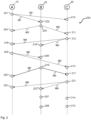
- FIG. 2 shows a schematic flowchart of a method 200 for determining a clock frequency offset and a clock phase offset according to another embodiment of the disclosure.
- the flowchart of the method 200 shows messages being exchanged between a first device 10, a second device 20 and a third device 30 in order to determine clock frequency offsets and clock phase offsets between those devices 10, 20, 30.
- the first and second device 10, 20 may correspond to those described with reference to Figure 1 .
- the third device has a third clock, not shown herein.
- a sending of a first message M1 in a step 201, a receiving of the first message M1 in a step 202, a sending of a third message M3 in a step 203, a receiving of the third message M3 in a step 204, a sending of a second message M2 in a step 205 and a receiving of the second message M2 in a step 206 may be performed according to the corresponding steps as described with respect to Figure 1 and is not repeated herein.
- the first message M1 is also sent from the first device 10 to the third device 30.
- the first message M1 is broadcast and received by both, the second and third device 20, 30.
- the first message M1 is received by the third device 30 in a step 210.
- the first message M1 could also be sent as two separate messages to the second and third device 20, 30, at the same or different moments in time. This may apply to any of the messages discussed herein and is not repeated in the following.
- the third device 30 Analogously to the receiving of the first message M1 by the second device 20 in step 202, the third device 30 detects a time of arrival ta 1 C of the first message M1 at the third device 30, which is measured using the third clock of the third device 30, and stores the time of arrival ta 1 C . The third device 30 further obtains the time of departure td 1 A of the first message M1 from the first message M1 and stores it.
- step 203 the third message M3 having the time of departure td 3 B is broadcast by the second device 20 and received, in addition to the receiving of the third message M3 by the first device 10, by the third device 30 in a step 211.
- a time of arrival ta 3 C of the third message M3 at the third device 30 is measured and stored by the third device 30, and the time of departure td 3 B is obtained from the third message M3 and stored by the third device 30.
- the third device 30 broadcasts a fourth message M4.
- the fourth message M4 has embedded a time of departure td 4 C of the fourth message M4.
- the fourth message M4 may contain the time of arrival ta 1 C of the first message M1 at the third device 30 and/or the fourth message M4 may contain the time of arrival ta 3 C of the third message M3 at the third device 30.
- the fourth message M4 is received, by the first and second device 10, 20, respectively, at steps 218 and 219.
- step 205 Analogously to the first message M1, in step 205 also the second message M2 is broadcast, by the first device 10.
- the second message M2 is received in a step 213, in addition to the receiving of the second message M2 by the second device 20, by the third device 30 at a time of arrival ta 2 C of the second message M2 at the third device 30, which is measured by the third clock of the third device 30 and stored by the third device 30.
- the second device 20 determines a clock frequency offset f 0 BA and a clock phase offset ⁇ 0 BA between the first clock of the first device 10 and the second clock of the second device 20. This corresponds to the step 107 as described with reference to Figure 1 and may be determined, for example, according to the equations discussed with regard to Figure 1 .
- a clock frequency offset f 0 CA and a clock phase offset ⁇ 0 CA between the first clock of the first device 10 and the third clock of the third device 20 may be determined by the third device 30.
- the clock frequency offset f 0 CA and the clock phase offset ⁇ 0 CA may therefore be determined based only on the times of arrival and times of departure of the first, second and fourth message.
- the second device 20 then synchronizes its second clock to the first clock according to the determined clock frequency offset f 0 BA and the determined clock phase offset ⁇ 0 BA .
- the third device 30 synchronizes its third clock to the first clock according to the determined clock frequency offset f 0 CA and the determined clock phase offset ⁇ 0 CA .
- the sending of the first, third and fourth message M1, M3, M4 is part of a periodic sending of those respective messages.
- the sending of the second message M2 is, in fact, a periodic repetition of the sending of the first message M1.
- the second device 20 may further broadcast a fifth message M5, corresponding to the sending of the third message M3, at a time of departure td 5 B at a step 216, the fifth message M5 having the time of departure td 5 B embedded in the fifth message M5.
- the third device 30 may receive the fifth message M5 at a time of arrival ta 5 C at a step 217, the first device 10 may receive the fifth message M5 at a time of arrival ta 5 A at a step 220.
- the third device 30 also broadcasts a sixth message M6 at a step 221 according to said periodicity.
- the sixth message M6 is received by the first and second device 10, 20, respectively, at steps 222 and 223. This generally corresponds to the sending and receiving of the previous messages, and details are not repeated herein.
- the third device 30 may also determine a clock frequency offset f 0 CB and a clock phase offset ⁇ 0 CB between the second device 20 and the third device 30. The third device 30 may then, alternatively to synchronizing its third clock to the first clock of the first device 10, synchronize its third clock to the second clock of the second device 20.
- the third device 30 may also determine a weighted zero mean error of its third clock based on the clock frequency offsets f 0 CA and f 0 CB and the clock phase offsets ⁇ 0 CA and ⁇ 0 CB . In that case, instead of synchronizing its third clock to a single other device, the third device may correct its timing values based on said weighted zero mean error, i.e., based on a weighted average of the offsets from the first and second devices 10, 20.
- the method 200 is scalable with respect to the number of devices determining the respective clock phase offsets and clock frequency offsets and the scope of the disclosure shall not be limited with regard to the three devices shown in Figure 2 .
- the respective clocks of the devices 10, 20, 30 may be tracked and synchronized continuously.
- the respective clock frequency offsets and clock phase offsets may be determined periodically and the synchronizing of the clocks may be performed periodically. This is in particular advantageous in mobile and fluid networks that are not fixed with continually changing connectivities because fully redundant clock tracking is made possible.
- the determining of the respective clock phase offsets and clock frequency offsets and the corresponding synchronization of the respective clocks is shown after two cycles of the periodic sending of the messages M1 to M3, i.e., M1 to M6 in total.
- the periodic determining of those offsets and the periodic synchronizing may be performed once the required messages and respective times of arrival and times of departure for determining the offsets according to the above-described method have been sent and received.
- FIG. 3 shows a system 300 according to one embodiment of the disclosure.
- the system 300 may be, for example, a 5G small cell or an indoor positioning system.
- the system 300 comprises a first apparatus 301 and a second apparatus 302.
- the first and second apparatus 301, 302 may be, for example, anchors of the aforementioned indoor positioning system.
- only two apparatuses 301, 302 are shown herein.
- the system 300 may, of course, also comprise further apparatuses corresponding to those described herein.
- the system 300 further comprises a central controlling entity 303.
- the central controlling entity may be, for example, a GNSS receiver of the aforementioned indoor positioning system, which may be used as a gateway to synchronize the first and second apparatus 301, 302 of the indoor positioning system to a GNSS satellite, wherein the first and second apparatus 301, 302 are out of sight of the GNSS satellite.
- the central controlling apparatus 303 in this case, is synchronized to a GNSS satellite, not shown herein.
- the first apparatus 301 comprises a first clock 304, a first receiver 305, a first transmitter 306 and a first processor 307.
- the second apparatus 302 comprises a second clock 308, a second receiver 309, a second transmitter 310 and a second processor 311.
- the central controlling entity 303 comprises a third receiver 312, a third transmitter 313, a third processor 314 and a third clock 316.
- the third cock 316 is synchronized to a GNSS satellite, and therefore serves as a master clock for the system 300.
- the central controlling entity 303, the first apparatus 301 and the second apparatus 302 may communicate with each other via a wireless network 315.
- the central controlling entity 303 broadcasts a first message using its third transmitter 313 via the wireless network 315 and the first message is received by the second apparatus 302 and the first apparatus 301 with their respective receivers 309, 305.
- the first message is broadcast by the central controlling entity 303 according to a predetermined schedule, which is known to the first and second apparatus 301, 302.
- the first message is broadcast, for example, every 100 milliseconds according to a Wireless-Fidelity, Wi-Fi, standard, i.e., a standard according to the IEEE 802.11 family of standards.
- the first message may also be broadcast, for example, every second, or even every 10 seconds.
- the first and second apparatus 301, 302 When the first and second apparatus 301, 302 receive the first message, the first and second apparatus 301, 302, according to the schedule, each know that the central controlling entity 303 passed the beginning of such 100 millisecond period, according to its third clock 316, which in this case is used as a reference for a time of departure of the first message. This reference is unambiguous, since the apparatuses 301, 302 and the central controlling entity 303 are located so close to each other in the system 300, that a transmission time of the message is shorter than the period for the sending of the scheduled message.
- the first apparatus 301 broadcasts a third message using its first transmitter 306 via the wireless network 315.
- the third message is also broadcast according to a scheduling, such that the central controlling entity 303 and the second apparatus 302 obtain, when receiving the third message, a time of departure of the third message according to the schedule, as discussed with reference to the first message above.
- the central controlling entity 303 is arranged to broadcast a second message, according to a schedule, having embedded a time of arrival of the third message at the central controlling entity 303 measured by the third clock 316.
- the first and second apparatus 301, 302 receive the second message, the first and second apparatus 301, 302 obtain the time of arrival of the third message at the central controlling entity 303 and the time of departure of the second message, analogously to the above.
- the second apparatus 302 may also broadcast a fourth message, which may be received by the central controlling entity 303 and the first apparatus 301.
- the first processor 307 of the first apparatus 301 is then able to determine a clock phase offset and a clock frequency offset of the first clock 304 from the third clock 316 based on the obtained timing information from the first, second and third messages.
- the second processor 311 of the second apparatus 302 is able to determine a clock phase offset and a clock frequency offset of the second clock 308 from the third clock 316 based on the obtained timing information from the first, second and fourth messages. This may be done according to the equations discussed with respect to Figures 1 and 2 .
- the first apparatus 301 may then, with its first processor 307, correct timing values of the first clock 304 based on the obtained offsets.
- the second apparatus 302 may then, with its second processor 311, correct timing values of the second clock 308 based on the obtained offsets.
- the central controlling entity 303 determines offsets of the clocks of the first and second apparatus 301, 302 and to communicate those to the respective apparatus.
- a weighted zero mean error may be determined, based on which of the clocks of the first and second apparatus 301, 302 are corrected, as discussed above with regard to Figure 2 .
- said apparatus may still synchronize its respective clock indirectly to the third clock 316 of the central controlling entity 303, which serves as a master clock, by synchronizing its clock to the clock of the other apparatus, which is synchronized to the third clock 316.
- the second apparatus 302 cannot receive messages from the central controlling entity 303. However, the second apparatus 302 still receives messages from the first apparatus 301 and vice versa, and the first apparatus 301 receives messages from the central controlling entity 303 and vice versa.
- the first apparatus 301 synchronizes the first clock 304 to the third clock 316 according to the exchange of messages described above.
- the second apparatus synchronizes the second clock 308 to the first clock 304 corresponding to the above, based on the third, fourth and a fifth message as described with respect to the method as shown in Figure 2 . This way, the second apparatus 302 may still synchronize its second clock 308 to the third clock 316, even when the second apparatus 302 cannot receive the first and second message broadcast by the central controlling entity 303.
- Figure 4 shows a schematic flowchart of a method 400 for determining a clock frequency offset according to one embodiment of the disclosure.
- At least one second device receives at least one first message from a first device, wherein information regarding a time of departure of the at least one first message is in the at least one first message.
- the at least one second device determines a time of arrival of the at least one first message.
- the at least one second device receives at least one second message from the first device, wherein information regarding a time of departure of the at least one second message is in the at least one second message.
- the at least one second device determines a time of arrival of the at least one second message.
- a clock frequency offset between the first clock and the at least one second clock is determined based on the time of departure of the at least one first message, the time of arrival of the at least one first message, the time of departure of the at least one second message, and the time of arrival of the at least one second message.
- FIG. 5 shows an apparatus 500 according to one embodiment of the disclosure.
- the apparatus 500 comprises a processor 501, a receiver 502 and a second clock 503.
- the receiver 502 is arranged to receive a first message from a first device, wherein information regarding a time of departure of the first message is in the first message, and to receive a second message from the first device, wherein information regarding a time of departure of the second message is in the second message.
- the processor 501 is arranged to determine a time of arrival of the first message and a time of arrival of the second message, wherein a clock frequency offset between a first clock of the first device and the second clock 503 is determined based on the time of departure of the first message, the time of arrival of the first message, the time of departure of the second message, and the time of arrival of the second message.
Landscapes
- Engineering & Computer Science (AREA)
- Computer Networks & Wireless Communication (AREA)
- Signal Processing (AREA)
- Synchronisation In Digital Transmission Systems (AREA)
- Electric Clocks (AREA)
- Position Fixing By Use Of Radio Waves (AREA)
Claims (15)
- Procédé (400) pour déterminer un décalage de fréquence d'horloge entre un premier dispositif ayant une première horloge et au moins un second dispositif ayant au moins une seconde horloge, le procédé comprenant :- recevoir (401), par l'au moins un deuxième dispositif, d'au moins un premier message provenant du premier dispositif, dans lequel une information concernant une heure de départ de l'au moins un premier message est dans l'au moins un premier message ;- déterminer (402), par l'au moins un deuxième dispositif, une heure d'arrivée de l'au moins un premier message ;- recevoir (403), par l'au moins un deuxième dispositif, d'au moins un deuxième message en provenance du premier dispositif, dans lequel une information concernant une heure de départ de l'au moins un deuxième message étant contenue dans l'au moins un deuxième message ;- déterminer (404), par l'au moins un deuxième dispositif, une heure d'arrivée de l'au moins un deuxième message ; et- déterminer (405) un décalage de fréquence d'horloge entre la première horloge et l'au moins une deuxième horloge en fonction de l'heure de départ de l'au moins un premier message, de l'heure d'arrivée de l'au moins un premier message, de l'heure de départ de l'au moins un deuxième message et de l'heure d'arrivée de l'au moins un deuxième message, le décalage de fréquence d'horloge entre la première horloge et l'au moins une deuxième horloge étant déterminé selon la formule suivante :
 - dans lequel :


- Procédé (400) selon la revendication 1, dans laquelle- l'heure de départ de l'au moins un premier message est une heure, liée à la première horloge, à laquelle l'au moins un premier message est envoyé par le premier dispositif ;- l'heure d'arrivée de l'au moins un premier message est une heure, liée à l'au moins une deuxième horloge, à laquelle l'au moins un premier message est reçu par l'au moins un deuxième dispositif ;- l'heure de départ de l'au moins un deuxième message est une heure, liée à la première horloge, à laquelle l'au moins un deuxième message est envoyé par le premier dispositif ; et- l'heure d'arrivée de l'au moins un deuxième message est une heure, liée à l'au moins une deuxième horloge, à laquelle l'au moins un deuxième message est reçu par l'au moins un deuxième dispositif.
- Procédé (400) selon l'une des revendications 1 ou 2, dans laquelle la procédé comprend en outre :- envoyer, par l'au moins un deuxième dispositif, d'au moins un troisième message au premier dispositif, une heure de départ de l'au moins un troisième message étant déterminée par l'au moins un deuxième dispositif ; et- déterminer un décalage de phase entre la première horloge et au moins une deuxième horloge en fonction de l'heure d'arrivée de l'au moins un premier message, de l'heure de départ de l'au moins un premier message, de l'heure d'arrivée de l'au moins un deuxième message, de l'heure de départ de l'au moins un deuxième message, de l'heure de départ de l'au moins un troisième message et de une heure d'arrivée de l'au moins un troisième message.
- Procédé (400) selon la revendication 3, dans laquelle- l'heure de départ de l'au moins un troisième message est une heure, liée à l'au moins une deuxième horloge, à laquelle l'au moins un troisième message est envoyé par l'au moins un deuxième dispositif ; et- l'heure d'arrivée de l'au moins un troisième message est une heure, liée à la première horloge, à laquelle l'au moins un troisième message est reçu par le premier dispositif.
- Procédé (400) selon l'une des revendications 1 à 4, dans lequel l'information concernant l'heure de départ de l'au moins un premier message et/ou de l'au moins un deuxième message et/ou de l'au moins un troisième message est contenue dans l'au moins un premier et/ou deuxième et/ou troisième message :- intégré sous forme d'horodatage dans l'au moins un premier et/ou deuxième et/ou troisième message ; ou- dérivé d'un ordonnancement prédéterminé de l'au moins un premier et/ou deuxième et/ou troisième message.
- Procédé (400) selon l'une des revendications 1 à 5, dans lequel le procédé comprend en outre l'étape :- synchroniser l'au moins une seconde horloge avec la première horloge sur la base du décalage de fréquence d'horloge déterminé et/ou sur la base du décalage de phase d'horloge déterminé ; ou- synchroniser la première horloge avec au moins une deuxième horloge sur la base du décalage de fréquence d'horloge déterminé et/ou sur la base du décalage de phase d'horloge déterminé.
- Procédé (400) selon la revendication 6, dans lequel la synchronisation d'au moins une seconde ou de la première horloge comprend le décalage des valeurs temporelles de l'au moins une seconde ou de la première horloge.
- Procédé (400) selon l'une des revendications 6 ou 7, dans lequel, en cas de l'au moins un premier message et l'au moins un deuxième message sont reçus par au moins deux deuxièmes dispositifs et au moins deux troisièmes messages sont envoyés par au moins deux deuxièmes dispositifs :- l'au moins une seconde horloge et/ou la première horloge sont synchronisées par rapport aux autres horloges des au moins deux secondes horloges et/ou de la première horloge sur la base d'une erreur moyenne nulle pondérée ; ou- l'au moins une seconde horloge et/ou la première horloge sont synchronisées avec l'une des autres horloges parmi les deux secondes horloges au moins et/ou la première horloge, qui sert d'horloge maîtresse.
- Appareil (500) comprenant un processeur (501), un récepteur (502) et une seconde horloge (503), dans lequel :- le récepteur (502) est conçu pour recevoir un premier message d'un premier dispositif, le premier message contenant des informations sur une heure de départ du premier message, et pour recevoir un deuxième message du premier dispositif, le deuxième message contenant des informations sur une heure de départ du deuxième message ; et- le processeur (501) est conçu pour déterminer une heure d'arrivée du premier message et une heure d'arrivée du second message, un décalage de fréquence d'horloge entre une première horloge du premier dispositif et la seconde horloge (503) étant déterminé en fonction de l'heure de départ du premier message, de l'heure d'arrivée du premier message, de l'heure de départ du second message et de l'heure d'arrivée du second message, le processeur (501) étant conçu pour déterminer le décalage de fréquence d'horloge entre la première horloge et l'au moins une seconde horloge selon la formule suivante :
 - dans lequel :


- L'appareil (500) selon la revendication 9, comprenant en outre un émetteur, dans lequel :- l'émetteur est conçu pour envoyer un troisième message au premier dispositif ; et- le processeur (502) est en outre conçu pour déterminer une heure de départ du troisième message, un décalage de phase d'horloge entre la première horloge et la deuxième horloge (503) étant déterminé en fonction de l'heure d'arrivée du premier message, de l'heure de départ du premier message, de l'heure d'arrivée du deuxième message, de l'heure de départ du deuxième message, de l'heure de départ du troisième message et d'une heure d'arrivée du troisième message.
- L'appareil (500) selon l'une des revendications 9 ou 10, dans lequel le décalage de la fréquence de l'horloge et/ou, en cas de dépendance de la revendication 10, le décalage de la phase de l'horloge est déterminé par le processeur (501) de l'appareil ou par un dispositif externe.
- L'appareil (500) selon l'une des revendications 9 à 11, dans lequel le processeur (501) est en outre conçu pour synchroniser la seconde horloge avec la première horloge sur la base du décalage de fréquence d'horloge déterminé et/ou du décalage de phase d'horloge déterminé en décalant les valeurs temporelles de la seconde horloge (503)
- Système comprenant un premier dispositif et au moins un appareil (500) selon l'une des revendications 9 à 12.
- Produit de programme informatique comprenant des instructions qui, lorsqu'elles sont exécutées sur un ordinateur, permettent à ce dernier d'appliquer la procédé décrite dans l'une des revendications 1 à 8.
- Support de stockage lisible par ordinateur comprenant le produit de programme informatique selon la revendication 14.
Priority Applications (3)
| Application Number | Priority Date | Filing Date | Title |
|---|---|---|---|
| EP21214375.4A EP4199384B1 (fr) | 2021-12-14 | 2021-12-14 | Procédé et appareil pour déterminer un décalage de fréquence d'horloge |
| US18/079,326 US20230188238A1 (en) | 2021-12-14 | 2022-12-12 | Method and apparatus for determining a clock frequency offset |
| CN202211592927.XA CN116264731A (zh) | 2021-12-14 | 2022-12-13 | 确定时钟频率偏移的方法和设备 |
Applications Claiming Priority (1)
| Application Number | Priority Date | Filing Date | Title |
|---|---|---|---|
| EP21214375.4A EP4199384B1 (fr) | 2021-12-14 | 2021-12-14 | Procédé et appareil pour déterminer un décalage de fréquence d'horloge |
Publications (2)
| Publication Number | Publication Date |
|---|---|
| EP4199384A1 EP4199384A1 (fr) | 2023-06-21 |
| EP4199384B1 true EP4199384B1 (fr) | 2025-06-18 |
Family
ID=79024424
Family Applications (1)
| Application Number | Title | Priority Date | Filing Date |
|---|---|---|---|
| EP21214375.4A Active EP4199384B1 (fr) | 2021-12-14 | 2021-12-14 | Procédé et appareil pour déterminer un décalage de fréquence d'horloge |
Country Status (3)
| Country | Link |
|---|---|
| US (1) | US20230188238A1 (fr) |
| EP (1) | EP4199384B1 (fr) |
| CN (1) | CN116264731A (fr) |
Families Citing this family (1)
| Publication number | Priority date | Publication date | Assignee | Title |
|---|---|---|---|---|
| WO2023009855A2 (fr) * | 2021-07-29 | 2023-02-02 | Spearix Technologies, Inc. | Synchronisation précise d'horloge et détection d'emplacement dans des réseaux sans fil sensibles au temps |
Family Cites Families (8)
| Publication number | Priority date | Publication date | Assignee | Title |
|---|---|---|---|---|
| SE513899C2 (sv) * | 1999-01-12 | 2000-11-20 | Ericsson Telefon Ab L M | Metod och arrangemang för synkronisering |
| GB0913367D0 (en) * | 2009-07-31 | 2009-09-16 | Omnisense Ltd | Positioning systems |
| JP2013083450A (ja) * | 2011-10-06 | 2013-05-09 | Sony Corp | 時刻制御装置、時刻制御方法、およびプログラム |
| EP3375113A4 (fr) * | 2015-11-09 | 2019-07-17 | Wiser Systems, Inc. | Procédés de synchronisation de multiples dispositifs et de détermination d'un emplacement en fonction des dispositifs synchronisés |
| US10778144B2 (en) * | 2017-12-22 | 2020-09-15 | Wiser Systems, Inc. | Methods for correcting oscillator offsets in ultra-wideband (UWB) networks |
| US11329746B2 (en) * | 2018-03-14 | 2022-05-10 | Telefonaktiebolaget Lm Ericsson (Publ) | Method and a first device for clock synchronization |
| US10911211B1 (en) * | 2018-09-28 | 2021-02-02 | ZaiNar, Inc. | Frequency and gain calibration for time synchronization in a network |
| IT202100022919A1 (it) * | 2021-09-06 | 2023-03-06 | Marelli Europe Spa | Procedimento di protezione da attacchi informatici a un veicolo basato su analisi temporale e corrispondente dispositivo |
-
2021
- 2021-12-14 EP EP21214375.4A patent/EP4199384B1/fr active Active
-
2022
- 2022-12-12 US US18/079,326 patent/US20230188238A1/en active Pending
- 2022-12-13 CN CN202211592927.XA patent/CN116264731A/zh active Pending
Also Published As
| Publication number | Publication date |
|---|---|
| CN116264731A (zh) | 2023-06-16 |
| US20230188238A1 (en) | 2023-06-15 |
| EP4199384A1 (fr) | 2023-06-21 |
Similar Documents
| Publication | Publication Date | Title |
|---|---|---|
| Hasan et al. | Time synchronization in vehicular ad-hoc networks: A survey on theory and practice | |
| US8116405B2 (en) | Method and apparatus for time synchronization using GPS information in communication system | |
| US7191354B2 (en) | Method for synchronizing a first clock to a second clock, processing unit and synchronization system | |
| US7876790B2 (en) | Apparatus and method for performing time synchronization using GPS information in communication system | |
| US20090086764A1 (en) | System and method for time synchronization on network | |
| US8873589B2 (en) | Methods and devices for clock synchronization | |
| CA2877720C (fr) | Systeme pour maintenir une heure precise sur une horloge ideale | |
| US7865331B2 (en) | Estimating a time offset between stationary clocks | |
| KR20170095234A (ko) | 네트워크 디바이스들의 클록들을 동기화하는 방법 | |
| US8638774B2 (en) | Controlling timing of synchronization updates | |
| EP2777183B1 (fr) | Détermination d'intervalle de synchronisation | |
| CN102983927B (zh) | 一种基于ieee 1588协议的主从时钟对时的时间补偿方法 | |
| WO2011025746A1 (fr) | Mesure et réglage de valeurs en temps réel selon un temps de séjour dans un équipement de mise en réseau sans accès au temps réel | |
| CN102546071A (zh) | 一种时钟同步方法与系统 | |
| US10320507B2 (en) | Method for determining a propagation time of a telegram in a communication network, and corresponding network components | |
| CN106664145A (zh) | 用于在通信网络中传输时间同步消息的方法、网络部件和通信网络 | |
| EP3935764B1 (fr) | Entités de réseau et procédés pour un système de réseau sans fil pour déterminer des informations de temps | |
| US20230397141A1 (en) | Method and apparatus for synchronising apparatuses of a wireless network | |
| WO2023236141A1 (fr) | Décalage de numéro de trame pour le positionnement d'un ue distant | |
| AU4297999A (en) | Absolute time synchronization for mobile positioning in a cellular communications system | |
| EP4199384B1 (fr) | Procédé et appareil pour déterminer un décalage de fréquence d'horloge | |
| CN111711506A (zh) | 一种通讯系统及其授时方法 | |
| US20180152903A1 (en) | Real-time wireless positioning system and method thereof | |
| JP2012195840A (ja) | 通信装置、通信制御方法 | |
| EP4108011B1 (fr) | Synchronisation d'horloges améliorée |
Legal Events
| Date | Code | Title | Description |
|---|---|---|---|
| PUAI | Public reference made under article 153(3) epc to a published international application that has entered the european phase |
Free format text: ORIGINAL CODE: 0009012 |
|
| STAA | Information on the status of an ep patent application or granted ep patent |
Free format text: STATUS: THE APPLICATION HAS BEEN PUBLISHED |
|
| AK | Designated contracting states |
Kind code of ref document: A1 Designated state(s): AL AT BE BG CH CY CZ DE DK EE ES FI FR GB GR HR HU IE IS IT LI LT LU LV MC MK MT NL NO PL PT RO RS SE SI SK SM TR |
|
| STAA | Information on the status of an ep patent application or granted ep patent |
Free format text: STATUS: REQUEST FOR EXAMINATION WAS MADE |
|
| 17P | Request for examination filed |
Effective date: 20231220 |
|
| RBV | Designated contracting states (corrected) |
Designated state(s): AL AT BE BG CH CY CZ DE DK EE ES FI FR GB GR HR HU IE IS IT LI LT LU LV MC MK MT NL NO PL PT RO RS SE SI SK SM TR |
|
| GRAP | Despatch of communication of intention to grant a patent |
Free format text: ORIGINAL CODE: EPIDOSNIGR1 |
|
| STAA | Information on the status of an ep patent application or granted ep patent |
Free format text: STATUS: GRANT OF PATENT IS INTENDED |
|
| INTG | Intention to grant announced |
Effective date: 20250117 |
|
| GRAS | Grant fee paid |
Free format text: ORIGINAL CODE: EPIDOSNIGR3 |
|
| GRAA | (expected) grant |
Free format text: ORIGINAL CODE: 0009210 |
|
| STAA | Information on the status of an ep patent application or granted ep patent |
Free format text: STATUS: THE PATENT HAS BEEN GRANTED |
|
| AK | Designated contracting states |
Kind code of ref document: B1 Designated state(s): AL AT BE BG CH CY CZ DE DK EE ES FI FR GB GR HR HU IE IS IT LI LT LU LV MC MK MT NL NO PL PT RO RS SE SI SK SM TR |
|
| REG | Reference to a national code |
Ref country code: GB Ref legal event code: FG4D |
|
| REG | Reference to a national code |
Ref country code: CH Ref legal event code: EP |
|
| REG | Reference to a national code |
Ref country code: DE Ref legal event code: R096 Ref document number: 602021032403 Country of ref document: DE |
|
| REG | Reference to a national code |
Ref country code: CH Ref legal event code: EP |
|
| REG | Reference to a national code |
Ref country code: IE Ref legal event code: FG4D |
|
| PG25 | Lapsed in a contracting state [announced via postgrant information from national office to epo] |
Ref country code: FI Free format text: LAPSE BECAUSE OF FAILURE TO SUBMIT A TRANSLATION OF THE DESCRIPTION OR TO PAY THE FEE WITHIN THE PRESCRIBED TIME-LIMIT Effective date: 20250618 |
|
| REG | Reference to a national code |
Ref country code: LT Ref legal event code: MG9D |
|
| PG25 | Lapsed in a contracting state [announced via postgrant information from national office to epo] |
Ref country code: NO Free format text: LAPSE BECAUSE OF FAILURE TO SUBMIT A TRANSLATION OF THE DESCRIPTION OR TO PAY THE FEE WITHIN THE PRESCRIBED TIME-LIMIT Effective date: 20250918 Ref country code: GR Free format text: LAPSE BECAUSE OF FAILURE TO SUBMIT A TRANSLATION OF THE DESCRIPTION OR TO PAY THE FEE WITHIN THE PRESCRIBED TIME-LIMIT Effective date: 20250919 |
|
| PG25 | Lapsed in a contracting state [announced via postgrant information from national office to epo] |
Ref country code: BG Free format text: LAPSE BECAUSE OF FAILURE TO SUBMIT A TRANSLATION OF THE DESCRIPTION OR TO PAY THE FEE WITHIN THE PRESCRIBED TIME-LIMIT Effective date: 20250618 |
|
| PG25 | Lapsed in a contracting state [announced via postgrant information from national office to epo] |
Ref country code: HR Free format text: LAPSE BECAUSE OF FAILURE TO SUBMIT A TRANSLATION OF THE DESCRIPTION OR TO PAY THE FEE WITHIN THE PRESCRIBED TIME-LIMIT Effective date: 20250618 |
|
| PG25 | Lapsed in a contracting state [announced via postgrant information from national office to epo] |
Ref country code: RS Free format text: LAPSE BECAUSE OF FAILURE TO SUBMIT A TRANSLATION OF THE DESCRIPTION OR TO PAY THE FEE WITHIN THE PRESCRIBED TIME-LIMIT Effective date: 20250918 |
|
| REG | Reference to a national code |
Ref country code: NL Ref legal event code: MP Effective date: 20250618 |
|
| PG25 | Lapsed in a contracting state [announced via postgrant information from national office to epo] |
Ref country code: LV Free format text: LAPSE BECAUSE OF FAILURE TO SUBMIT A TRANSLATION OF THE DESCRIPTION OR TO PAY THE FEE WITHIN THE PRESCRIBED TIME-LIMIT Effective date: 20250618 |
|
| PG25 | Lapsed in a contracting state [announced via postgrant information from national office to epo] |
Ref country code: NL Free format text: LAPSE BECAUSE OF FAILURE TO SUBMIT A TRANSLATION OF THE DESCRIPTION OR TO PAY THE FEE WITHIN THE PRESCRIBED TIME-LIMIT Effective date: 20250618 |
|
| PG25 | Lapsed in a contracting state [announced via postgrant information from national office to epo] |
Ref country code: PT Free format text: LAPSE BECAUSE OF FAILURE TO SUBMIT A TRANSLATION OF THE DESCRIPTION OR TO PAY THE FEE WITHIN THE PRESCRIBED TIME-LIMIT Effective date: 20251020 |
|
| REG | Reference to a national code |
Ref country code: AT Ref legal event code: MK05 Ref document number: 1805178 Country of ref document: AT Kind code of ref document: T Effective date: 20250618 |
|
| PG25 | Lapsed in a contracting state [announced via postgrant information from national office to epo] |
Ref country code: IS Free format text: LAPSE BECAUSE OF FAILURE TO SUBMIT A TRANSLATION OF THE DESCRIPTION OR TO PAY THE FEE WITHIN THE PRESCRIBED TIME-LIMIT Effective date: 20251018 |
|
| PGFP | Annual fee paid to national office [announced via postgrant information from national office to epo] |
Ref country code: DE Payment date: 20251211 Year of fee payment: 5 |
|
| PGFP | Annual fee paid to national office [announced via postgrant information from national office to epo] |
Ref country code: GB Payment date: 20251219 Year of fee payment: 5 |
|
| PG25 | Lapsed in a contracting state [announced via postgrant information from national office to epo] |
Ref country code: AT Free format text: LAPSE BECAUSE OF FAILURE TO SUBMIT A TRANSLATION OF THE DESCRIPTION OR TO PAY THE FEE WITHIN THE PRESCRIBED TIME-LIMIT Effective date: 20250618 Ref country code: SM Free format text: LAPSE BECAUSE OF FAILURE TO SUBMIT A TRANSLATION OF THE DESCRIPTION OR TO PAY THE FEE WITHIN THE PRESCRIBED TIME-LIMIT Effective date: 20250618 |
|
| PGFP | Annual fee paid to national office [announced via postgrant information from national office to epo] |
Ref country code: FR Payment date: 20251229 Year of fee payment: 5 |
|
| PG25 | Lapsed in a contracting state [announced via postgrant information from national office to epo] |
Ref country code: CZ Free format text: LAPSE BECAUSE OF FAILURE TO SUBMIT A TRANSLATION OF THE DESCRIPTION OR TO PAY THE FEE WITHIN THE PRESCRIBED TIME-LIMIT Effective date: 20250618 |
|
| PG25 | Lapsed in a contracting state [announced via postgrant information from national office to epo] |
Ref country code: PL Free format text: LAPSE BECAUSE OF FAILURE TO SUBMIT A TRANSLATION OF THE DESCRIPTION OR TO PAY THE FEE WITHIN THE PRESCRIBED TIME-LIMIT Effective date: 20250618 |
|
| PG25 | Lapsed in a contracting state [announced via postgrant information from national office to epo] |
Ref country code: EE Free format text: LAPSE BECAUSE OF FAILURE TO SUBMIT A TRANSLATION OF THE DESCRIPTION OR TO PAY THE FEE WITHIN THE PRESCRIBED TIME-LIMIT Effective date: 20250618 |
|
| PG25 | Lapsed in a contracting state [announced via postgrant information from national office to epo] |
Ref country code: SK Free format text: LAPSE BECAUSE OF FAILURE TO SUBMIT A TRANSLATION OF THE DESCRIPTION OR TO PAY THE FEE WITHIN THE PRESCRIBED TIME-LIMIT Effective date: 20250618 |
|
| PG25 | Lapsed in a contracting state [announced via postgrant information from national office to epo] |
Ref country code: ES Free format text: LAPSE BECAUSE OF FAILURE TO SUBMIT A TRANSLATION OF THE DESCRIPTION OR TO PAY THE FEE WITHIN THE PRESCRIBED TIME-LIMIT Effective date: 20250618 |
|
| PG25 | Lapsed in a contracting state [announced via postgrant information from national office to epo] |
Ref country code: RO Free format text: LAPSE BECAUSE OF FAILURE TO SUBMIT A TRANSLATION OF THE DESCRIPTION OR TO PAY THE FEE WITHIN THE PRESCRIBED TIME-LIMIT Effective date: 20250618 |
|
| PG25 | Lapsed in a contracting state [announced via postgrant information from national office to epo] |
Ref country code: DK Free format text: LAPSE BECAUSE OF FAILURE TO SUBMIT A TRANSLATION OF THE DESCRIPTION OR TO PAY THE FEE WITHIN THE PRESCRIBED TIME-LIMIT Effective date: 20250618 |
|
| PG25 | Lapsed in a contracting state [announced via postgrant information from national office to epo] |
Ref country code: IT Free format text: LAPSE BECAUSE OF FAILURE TO SUBMIT A TRANSLATION OF THE DESCRIPTION OR TO PAY THE FEE WITHIN THE PRESCRIBED TIME-LIMIT Effective date: 20250618 |
|
| PLBE | No opposition filed within time limit |
Free format text: ORIGINAL CODE: 0009261 |
|
| STAA | Information on the status of an ep patent application or granted ep patent |
Free format text: STATUS: NO OPPOSITION FILED WITHIN TIME LIMIT |
|
| REG | Reference to a national code |
Ref country code: CH Ref legal event code: L10 Free format text: ST27 STATUS EVENT CODE: U-0-0-L10-L00 (AS PROVIDED BY THE NATIONAL OFFICE) Effective date: 20260430 |