EP4199534A1 - Dispositif d'orientation azimutale de la source sonore - Google Patents
Dispositif d'orientation azimutale de la source sonore Download PDFInfo
- Publication number
- EP4199534A1 EP4199534A1 EP21885710.0A EP21885710A EP4199534A1 EP 4199534 A1 EP4199534 A1 EP 4199534A1 EP 21885710 A EP21885710 A EP 21885710A EP 4199534 A1 EP4199534 A1 EP 4199534A1
- Authority
- EP
- European Patent Office
- Prior art keywords
- microphones
- concyclic
- sound source
- sound
- array sensor
- Prior art date
- Legal status (The legal status is an assumption and is not a legal conclusion. Google has not performed a legal analysis and makes no representation as to the accuracy of the status listed.)
- Pending
Links
Images





Classifications
-
- G—PHYSICS
- G01—MEASURING; TESTING
- G01S—RADIO DIRECTION-FINDING; RADIO NAVIGATION; DETERMINING DISTANCE OR VELOCITY BY USE OF RADIO WAVES; LOCATING OR PRESENCE-DETECTING BY USE OF THE REFLECTION OR RERADIATION OF RADIO WAVES; ANALOGOUS ARRANGEMENTS USING OTHER WAVES
- G01S3/00—Direction-finders for determining the direction from which infrasonic, sonic, ultrasonic or electromagnetic waves, or particle emission, not having a directional significance, are being received
- G01S3/80—Direction-finders for determining the direction from which infrasonic, sonic, ultrasonic or electromagnetic waves, or particle emission, not having a directional significance, are being received using ultrasonic, sonic or infrasonic waves
- G01S3/801—Details
-
- H—ELECTRICITY
- H04—ELECTRIC COMMUNICATION TECHNIQUE
- H04R—LOUDSPEAKERS, MICROPHONES, GRAMOPHONE PICK-UPS OR LIKE ACOUSTIC ELECTROMECHANICAL TRANSDUCERS; ELECTRIC HEARING AIDS; PUBLIC ADDRESS SYSTEMS
- H04R1/00—Details of transducers, loudspeakers or microphones
- H04R1/20—Arrangements for obtaining desired frequency or directional characteristics
- H04R1/32—Arrangements for obtaining desired frequency or directional characteristics for obtaining desired directional characteristic only
- H04R1/40—Arrangements for obtaining desired frequency or directional characteristics for obtaining desired directional characteristic only by combining a number of identical transducers
-
- H—ELECTRICITY
- H04—ELECTRIC COMMUNICATION TECHNIQUE
- H04R—LOUDSPEAKERS, MICROPHONES, GRAMOPHONE PICK-UPS OR LIKE ACOUSTIC ELECTROMECHANICAL TRANSDUCERS; ELECTRIC HEARING AIDS; PUBLIC ADDRESS SYSTEMS
- H04R1/00—Details of transducers, loudspeakers or microphones
- H04R1/20—Arrangements for obtaining desired frequency or directional characteristics
- H04R1/32—Arrangements for obtaining desired frequency or directional characteristics for obtaining desired directional characteristic only
- H04R1/40—Arrangements for obtaining desired frequency or directional characteristics for obtaining desired directional characteristic only by combining a number of identical transducers
- H04R1/406—Arrangements for obtaining desired frequency or directional characteristics for obtaining desired directional characteristic only by combining a number of identical transducers microphones
-
- G—PHYSICS
- G01—MEASURING; TESTING
- G01S—RADIO DIRECTION-FINDING; RADIO NAVIGATION; DETERMINING DISTANCE OR VELOCITY BY USE OF RADIO WAVES; LOCATING OR PRESENCE-DETECTING BY USE OF THE REFLECTION OR RERADIATION OF RADIO WAVES; ANALOGOUS ARRANGEMENTS USING OTHER WAVES
- G01S3/00—Direction-finders for determining the direction from which infrasonic, sonic, ultrasonic or electromagnetic waves, or particle emission, not having a directional significance, are being received
- G01S3/80—Direction-finders for determining the direction from which infrasonic, sonic, ultrasonic or electromagnetic waves, or particle emission, not having a directional significance, are being received using ultrasonic, sonic or infrasonic waves
- G01S3/802—Systems for determining direction or deviation from predetermined direction
- G01S3/808—Systems for determining direction or deviation from predetermined direction using transducers spaced apart and measuring phase or time difference between signals therefrom, i.e. path-difference systems
- G01S3/8083—Systems for determining direction or deviation from predetermined direction using transducers spaced apart and measuring phase or time difference between signals therefrom, i.e. path-difference systems determining direction of source
-
- G—PHYSICS
- G10—MUSICAL INSTRUMENTS; ACOUSTICS
- G10L—SPEECH ANALYSIS TECHNIQUES OR SPEECH SYNTHESIS; SPEECH RECOGNITION; SPEECH OR VOICE PROCESSING TECHNIQUES; SPEECH OR AUDIO CODING OR DECODING
- G10L25/00—Speech or voice analysis techniques not restricted to a single one of groups G10L15/00 - G10L21/00
- G10L25/48—Speech or voice analysis techniques not restricted to a single one of groups G10L15/00 - G10L21/00 specially adapted for particular use
- G10L25/51—Speech or voice analysis techniques not restricted to a single one of groups G10L15/00 - G10L21/00 specially adapted for particular use for comparison or discrimination
-
- H—ELECTRICITY
- H04—ELECTRIC COMMUNICATION TECHNIQUE
- H04R—LOUDSPEAKERS, MICROPHONES, GRAMOPHONE PICK-UPS OR LIKE ACOUSTIC ELECTROMECHANICAL TRANSDUCERS; ELECTRIC HEARING AIDS; PUBLIC ADDRESS SYSTEMS
- H04R1/00—Details of transducers, loudspeakers or microphones
- H04R1/08—Mouthpieces; Microphones; Attachments therefor
-
- H—ELECTRICITY
- H04—ELECTRIC COMMUNICATION TECHNIQUE
- H04R—LOUDSPEAKERS, MICROPHONES, GRAMOPHONE PICK-UPS OR LIKE ACOUSTIC ELECTROMECHANICAL TRANSDUCERS; ELECTRIC HEARING AIDS; PUBLIC ADDRESS SYSTEMS
- H04R3/00—Circuits for transducers
-
- H—ELECTRICITY
- H04—ELECTRIC COMMUNICATION TECHNIQUE
- H04R—LOUDSPEAKERS, MICROPHONES, GRAMOPHONE PICK-UPS OR LIKE ACOUSTIC ELECTROMECHANICAL TRANSDUCERS; ELECTRIC HEARING AIDS; PUBLIC ADDRESS SYSTEMS
- H04R2201/00—Details of transducers, loudspeakers or microphones covered by H04R1/00 but not provided for in any of its subgroups
- H04R2201/40—Details of arrangements for obtaining desired directional characteristic by combining a number of identical transducers covered by H04R1/40 but not provided for in any of its subgroups
- H04R2201/401—2D or 3D arrays of transducers
-
- H—ELECTRICITY
- H04—ELECTRIC COMMUNICATION TECHNIQUE
- H04R—LOUDSPEAKERS, MICROPHONES, GRAMOPHONE PICK-UPS OR LIKE ACOUSTIC ELECTROMECHANICAL TRANSDUCERS; ELECTRIC HEARING AIDS; PUBLIC ADDRESS SYSTEMS
- H04R2201/00—Details of transducers, loudspeakers or microphones covered by H04R1/00 but not provided for in any of its subgroups
- H04R2201/40—Details of arrangements for obtaining desired directional characteristic by combining a number of identical transducers covered by H04R1/40 but not provided for in any of its subgroups
- H04R2201/405—Non-uniform arrays of transducers or a plurality of uniform arrays with different transducer spacing
-
- H—ELECTRICITY
- H04—ELECTRIC COMMUNICATION TECHNIQUE
- H04R—LOUDSPEAKERS, MICROPHONES, GRAMOPHONE PICK-UPS OR LIKE ACOUSTIC ELECTROMECHANICAL TRANSDUCERS; ELECTRIC HEARING AIDS; PUBLIC ADDRESS SYSTEMS
- H04R2430/00—Signal processing covered by H04R, not provided for in its groups
- H04R2430/20—Processing of the output signals of the acoustic transducers of an array for obtaining a desired directivity characteristic
Definitions
- the present invention relates to a device for determining sound source direction including an array sensor capable of improving directivity while suppressing an increase in the number of microphones, as well as suppressing the occurrence of grating lobes.
- a device for determining sound source direction including an array sensor with a plurality of microphones arranged on a plane.
- this device it is necessary to increase the aperture in order to achieve high directivity.
- grating lobes due to the regularity of the phase difference of the sound pressure observed by the individual microphones, grating lobes (false signals) occur depending on the microphone arrangement, causing misdetermination.
- ⁇ wavelength
- Patent Literature 1 discloses that the occurrence of grating lobes can be suppressed without setting the microphone arrangement spacing to ⁇ /2 or less, by narrowing the search range of the sound source. As mentioned above, by narrowing the search range, the occurrence of grating lobes can be suppressed without setting the microphone spacing to ⁇ /2 or less. However, in order to improve directivity, it is necessary to further increase the aperture, and many microphones are required to suppress grating lobes while increasing the aperture.
- Patent Literature 2 discloses an array sensor in which spatial regularity is avoided by arranging array elements along the shape of a logarithmic spiral.
- Patent Literature 3 and 4 disclose technology for suppressing the regularity of the phase difference of the sound pressure observed by the individual microphones by having subarrays, though they have rotational symmetry as spatial regularity, thereby suppressing the occurrence of grating lobes.
- the present invention has been made in view of such background art, and an object thereof is to provide a device for determining sound source direction including an array sensor capable of improving directivity while suppressing an increase in the number of microphones, as well as suppressing the occurrence of grating lobes.
- the device for determining sound source direction includes an array sensor in which a plurality of microphones is provided at the vertices of two or more concyclic polygons that are on same plane and that have the same center, and are arranged so as to be non-rotationally symmetric as a whole array sensor. Because the array sensor is capable of improving directivity while suppressing an increase in the number of microphones, as well as suppressing the occurrence of grating lobes, the device for determining sound source direction including the array sensor is a device capable of determining the position of a sound source with high accuracy.
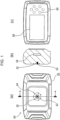
- Fig. 1 includes diagrams illustrating the overall configuration of a device for determining sound source direction 10 according to the present embodiment.
- Fig. 1(a) is a front view of the device for determining sound source direction 10
- Fig. 1(b) is a cross sectional view taken along A-A in Fig. 1(a)
- Fig. 1(c) is a back view of the device for determining sound source direction 10.
- the device for determining sound source direction 10 includes a camera 12, an array sensor 14, computing means 16, display means 18, input means 20, and a housing 22.
- the camera 12 and the array sensor 14 are provided on the front side of the housing 22
- the computing means 16 is provided inside the housing 22
- the display means 18 and the input means 20 are provided on the back side of the housing 22.
- the camera 12 captures an image of a measurement target and outputs the obtained captured image to the computing means 16.
- the captured image is used for the purpose of being superimposed with a two-dimensional map of sound pressure obtained by the beamforming method.
- the beamforming method refers to a calculation method of using the phase difference of a sound wave measured by a plurality of microphones to obtain the angle of arrival of the sound wave relative to the front direction of the microphones.
- the magnification, the width of the field of view, and the like of the camera 12 may be appropriately adjusted depending on a desired search range.
- the camera 12 is, for example, a digital camera equipped with an image sensor such as a CCD sensor or a CMOS sensor and a lens.
- the camera 12 is provided at the center of the array sensor 14. By providing the camera 12 at the center of the array sensor 14, when a map of sound pressure obtained by the beamforming method is superimposed on a captured image, the superimposed image of the map of sound pressure and the captured image can be created without mismatch regardless of the distance to the measurement target.
- the array sensor 14 includes a plurality of microphones 15.
- the microphones 15 measure a sound wave emitted from a sound source and output sound pressure information.
- the microphones 15 are provided at the vertices of two concyclic polygons that are on same plane and that have the same center, and the microphones 15 are arranged so as to be non-rotationally symmetric as a whole array sensor.
- the microphones 15 are sensitive to sound waves within a frequency range of 100 kHz from audible sound, and the obtained sound pressure information is subjected to beamforming calculations by the computing means with respect to a bandpass-filtered arbitrary measurement frequency.
- the microphones 15 may be sensitive to single wavelength or narrowband sound waves.
- Fig. 2 is a diagram illustrating the arrangement of the microphones 15 in the array sensor 14.
- the array sensor 14 includes thirteen microphones 15, for example.
- the thirteen microphones 15 are provided at the positions of the vertices of an outer concyclic regular heptagon whose circumscribed circle has a diameter of ⁇ 41 mm, and at the positions of the vertices of an inner concyclic regular hexagon whose circumscribed circle has a diameter of ⁇ 15.3 mm.
- the center of the circumscribed circle of the outer concyclic regular heptagon is the same as the center of the circumscribed circle of the inner concyclic regular hexagon, and the camera 12 is provided at that position.
- the frequency of the sound wave to be measured and the size of the circumscribed circle of each concyclic regular n-gon are not limited to the above.
- the measurement frequency may be selected from a frequency range of 100 kHz from audible sound (such as 20 Hz), and the size of the circumscribed circle of each concyclic regular n-gon may be appropriately set according to that frequency (wavelength).
- the thirteen microphones 15 are provided at the vertices of the outer concyclic regular heptagon and the inner concyclic regular hexagon, which are concyclic polygons having the same center, and the microphones 15 arranged as above are non-rotationally symmetric as a whole array sensor.
- being non-rotationally symmetric means an arrangement that, while the array sensor 14 is rotated 360° relative to the center of the circumscribed circles of the concyclic polygons, all the microphones 15 are not simultaneously arranged the same as before the rotation.
- the array sensor 14 is enabled to improve directivity while suppressing an increase in the number of microphones, and to suppress the occurrence of grating lobes.
- the computing means 16 creates a map of sound pressure indicating the sound pressure intensity of the sound wave according to each separated direction by performing beamforming calculations on sound pressure information measured by the array sensor 14.
- the computing means 16 creates a superimposed image by superimposing the map of sound pressure on a captured image obtained by the camera 12.
- the superimposed image is created by superimposing the map of sound pressure on the captured image.
- the subject and the sound pressure intensity are superimposed and displayed. So, when the user checks the superimposed image, the user can understand correspondence between the position of the subject in the captured image and the sound pressure distribution at a glance.
- the computing means 16 outputs the created superimposed image to the display means 18, and displays the superimposed image on the display means 18.
- the display means 18 may be a liquid crystal display (LCD), for example, which displays a superimposed image created by the computing means 16.
- the input means 20 may be, for example, push switches which are plurally provided near the display means 18. When the user presses the input means 20, a certain input signal is input to the computing means 16. Instead of or together with the push switches, the touchscreen-type input means 20 may be used.
- Fig. 3 is a functional block diagram of the device for determining sound source direction 10. Using Fig. 3 , the processing of the device for determining sound source direction 10 to display a superimposed image will be described.
- the computing means 16 includes a processor 30 and a storage 32.
- the processor 30 is, for example, a CPU or the like, which controls the operation of the device for determining sound source direction 10 using programs and data stored in the storage 32, and executes certain arithmetic operation.
- the storage 32 includes an information recording medium such as a re-recordable flash memory, a built-in hard disk or a hard disk connected by a data communication terminal, or a memory card, and a read/write device therefor.
- the storage 32 stores in advance programs for realizing various functions of the device for determining sound source direction 10, and various information used in executing the programs.
- the camera 12 captures an image of a measurement target.
- the camera 12 outputs the captured image to the processor 30.
- the array sensor 14 measures the sound pressure caused by a sound wave emitted from the direction of the measurement target.
- the array sensor 14 outputs the measured sound pressure as sound pressure information to the processor 30.
- the processor 30 divides a range corresponding to the field of view of the camera into a predetermined number of direction divisions, and performs beamforming calculations on sound pressure information obtained from the array sensor 14 to create a map of sound pressure corresponding to the image capturing area.
- the processor 30 creates a superimposed image by superimposing the map of sound pressure corresponding to the image capturing area on the captured image.
- the processor 30, for example, creates a superimposed image by making the map of sound pressure a transparent image and superimposing it on the captured image.
- the processor 30 calculates the sound pressure in each direction based on sound pressure information of the sound wave obtained by the array sensor 14, and determines a direction in which the sound pressure is maximum as the direction of sound wave arrival. At this time, the processor 30 determines the direction of sound wave arrival by beamforming calculations using, for example, a so-called delay and sum beamforming that determines the direction of the sound source from the time difference (phase difference) of sound pressure information detected by the individual microphones 15.
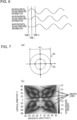
- Fig. 4 is a schematic diagram illustrating an example of the direction of sound wave arrival.
- the direction of sound wave arrival is the direction in which the sound source is located, and is expressed as an arrival angle ( ⁇ , ⁇ ) using an direction angle ⁇ relative to a direction (Z direction) perpendicular to an arrangement plane (XY plane) of the microphones 15 and an direction angle ⁇ relative to an arbitrary direction (such as the Y direction) serving as a reference on the arrangement surface (XY plane).
- the processor 30 uses sound pressure information detected by the microphones 15 to determine the arrival angle ( ⁇ , ⁇ ) using the delay and sum beamforming.
- Fig. 5 is a schematic diagram illustrating how sound wave information is detected by the microphones
- Fig. 6 is a graph illustrating an example of sound pressure information detected by each microphone.
- Figs. 5 and 6 illustrate by way of example for the case in which three microphones 15a to 15c are arranged.
- the microphone 15a serves as a reference microphone
- the sound wave reaches the microphone 15b with a gap of a time difference ⁇ relative to the microphone 15a.
- the time difference ⁇ (s) of the wave reaching the microphone 15a and the microphone 15b is obtained by equation (1) below using the sound velocity v (mm/s), the direction angle ⁇ , and the distance L between the microphones 15a and 15b is d (mm) .
- ⁇ L ⁇ sin ⁇ / v
- Equation (1) on the assumption that the sound wave arrives from the sound source that is sufficiently far away relative to the microphone spacing, the sound wave at the microphone 15c whose distance L from the reference microphone 15a is only the spacing 2d arrives with a time difference 2 ⁇ . Therefore, as illustrated in Fig. 6 , sound pressure information detected by each of the microphones 15a to 15c is shifted by the amount of the time difference ⁇ according to the distance L from the reference microphone 15a. Using the above, the processor 30 determines the arrival angle ( ⁇ , ⁇ ) of the sound wave.
- the processor 30 shifts the time of sound pressure information obtained by each of the microphones 15 by the amount of the time difference ⁇ , and calculates an added value by adding a plurality of items of time-shifted sound pressure information.
- a plurality of different time differences ⁇ corresponding to the arrival angle ( ⁇ , ⁇ ) is set in advance, and the plurality of different time differences ⁇ is set to the individual microphones 15 according to the distance L.
- the processor 30 uses the set different time differences ⁇ to change the amount of time to be shifted and obtains a plurality of added values.
- An added value obtained by an addition using the time difference ⁇ corresponding to the arrival angle ( ⁇ , ⁇ ) is the largest because the waveforms of items of sound pressure information are matched in phase.
- an added value obtained by an addition using the time difference ⁇ not corresponding to the arrival angle ( ⁇ , ⁇ ) is not large because the waveforms are not matched in phase and cancel each other out. Therefore, the processor 30 determines, among a plurality of added values obtained by sequentially changing an assumed arrival angle ( ⁇ ', ⁇ ') assumed within the sound source search range, an assumed arrival angle resulting in the largest added value as the direction of the sound source.
- the direction when the direction is determined by the delay and sum beamforming described above, it is desirable to use the array sensor 14 with characteristics that suppress the occurrence of grating lobes while increasing directivity by narrowing the beam width.
- the array sensor 14 in which the microphones 15 are arranged as illustrated in Fig. 2 characteristics that the beam width is narrow and that suppress the occurrence of grating lobes can be obtained (see Fig. 10 described later). Therefore, the direction can be determined with high accuracy by the delay and sum beamforming.
- Figs. 5 to 7 Although the delay and sum beamforming with which the processor 30 determines the arrival angle ( ⁇ , ⁇ ) based on the time difference ⁇ has been illustrated in Figs. 5 to 7 , this is not the only possible method, and various known methods can be applied.
- sound pressure information simultaneously observed by the microphones 15a to 15c is regarded as a two-dimensional spatial sound pressure field, and a two-dimensional Fourier transform is spatially performed to obtain a spatial frequency; and, by utilizing the correlation between the spatial frequency and the arrival angle ( ⁇ , ⁇ ), a sound source direction determination result that is almost equivalent to that of beamforming calculations using the delay and sum beamforming can also be obtained.
- the processor 30 displays a created superimposed image on the display means 18.
- a map of sound pressure used for a superimposed image to be displayed on the display means 18 a color image having successively different colors depending on the sound pressure intensity may be used.
- the processor 30 stores the camera image and the superimposed image in the storage 32.
- the device for determining sound source direction 10 creates a superimposed image as above and displays it on the display means 18.
- the sound source direction determination performance of the array sensor is greatly affected by the arrangement of the microphones 15.
- Directivity is an index indicating whether the sound pressure (hereinafter referred to as the "main lobe") of the sound source observed on the map of sound pressure can be displayed sharply, and the higher the directivity, the narrower the full width at half maximum (FWHM) of the main lobe, which is thus advantageous for determining the direction of the sound source.
- FWHM full width at half maximum
- the aperture is the diameter of a circle passing through the multiple microphones 15 arranged on the outer side, and, in the present embodiment, the aperture is the diameter of an outer concyclic polygon.
- the signal to noise ratio is the intensity ratio of the main lobe to the intensity of a grating lobe (false signal) and is calculated as (intensity of main lobe)/(intensity of grating lobe).
- a high signal to noise ratio means that the intensity of the grating lobe is sufficiently low compared to the intensity of the main lobe. If the intensity of the grating lobe can be reduced relative to the intensity of the main lobe, a misjudgment of the direction of the sound source due to the grating lobe can be suppressed. Accordingly, a high signal to noise ratio is advantageous for the determination of the direction of the sound source. In order to increase the signal to noise ratio, it is effective to increase the number of microphones 15 and narrow the arrangement spacing of the microphones 15, but it is preferable that the number of microphones 15 be as small as possible from the viewpoint of reducing the product cost and the computational load.
- the maps of sound pressure of various array sensors with different arrangements of the microphones 15 have been examined by simulation.
- the scale is generalized with a constant aperture relative to the measured wavelength; if the measured wavelength changes, the actual dimensions of aperture changes depending on the change in the wavelength.
- the size of the aperture relative to the wavelength of the measured sound wave is set to be constant (4 ⁇ : ⁇ is the wavelength of the sound wave), and each array sensor is evaluated in terms of the signal to noise ratio of the map of sound pressure and the position at which a highly intense grating lobe occurs.
- the simulation has been conducted using a sound velocity (about 348 m/s) in the air at a temperature of 25°C and a pressure of 1 atmosphere, assuming that the sound source is located 5 m in front of the device for determining sound source direction 10, and using a search range of ⁇ 85° in the vertical direction and ⁇ 85° in the horizontal direction relative to a sound wave (frequency 40 kHz) emitted from the sound source.
- Fig. 7 includes diagrams illustrating the result of simulating a map of sound pressure of an array sensor 40.
- Fig. 7(a) is a diagram illustrating the arrangement of the microphones 15 in the array sensor 40.
- Fig. 7(b) is a diagram illustrating a map of sound pressure created based on sound pressure information obtained by the array sensor 40 illustrated in Fig. 7(a) .
- Fig. 8 includes diagrams illustrating the result of simulating a map of sound pressure of an array sensor 42.
- Fig. 8(a) is a diagram illustrating the arrangement of the microphones 15 in the array sensor 42.
- Fig. 8(b) is a diagram illustrating a map of sound pressure created based on sound pressure information obtained by the array sensor 42 illustrated in Fig. 8(a) .
- the parameters of the simulation used to create Fig. 8(b) are entirely the same as those of Fig. 7 except for the arrangement of the microphones 15.
- the signal to noise ratio is 1.4, which is higher than the signal to noise ratio of the array sensor 42 illustrated in Fig. 7 .
- the arrangement using the vertices of a single concyclic regular polygon is confirmed to be effective for improving the signal to noise ratio.
- the intensity of grating lobes remains to be high, and the grating lobes occur around the main lobe at the center.
- both the main lobe and the grating lobes appear in the field of view, which causes a misjudgment of the position of the sound source and thus is undesirable. From this result, because the array sensor 42 is incapable of sufficiently suppressing the occurrence of grating lobes and grating lobes occur at positions close to the main lobe, it has been confirmed that the array sensor 42 is not desirable for determining the direction of the sound source.
- Fig. 9 includes diagrams illustrating the result of simulating a map of sound pressure of an array sensor 44.
- Fig. 9(a) is a diagram illustrating the arrangement of the microphones 15 in the array sensor 44.
- Fig. 9(b) is a diagram illustrating a map of sound pressure created based on sound pressure information obtained by the array sensor 44 illustrated in Fig. 9(a) .
- the parameters of the simulation used to create Fig. 9(b) are also entirely the same as those of Fig. 7 except for the arrangement of the microphones 15. In the case where the microphones 15 are arranged at the vertices of the single concyclic regular polygon illustrated in Fig.
- the signal to noise ratio is 1.7.
- grating lobes with relatively high intensity that are of equivalent size as the main lobe occur over a wide area around the main lobe at the center. Since the microphones 15 constituting the array sensor 44 are rotationally symmetric, there is regularity in the phase difference of the sound pressure obtained by the individual microphones 15, and it is considered that this regularity causes grating lobes.
- Fig. 10 includes diagrams illustrating the result of simulating a map of sound pressure of the array sensor 14.
- Fig. 10(a) is a diagram illustrating the arrangement of the microphones 15 in the array sensor 14.
- Fig. 10(b) is a diagram illustrating a map of sound pressure created based on sound pressure information obtained by the array sensor 14 illustrated in Fig. 10(a) .
- the parameters of the simulation used to create Fig. 10(b) are also entirely the same as those of Fig. 7 except for the arrangement of the microphones 15.
- the signal to noise ratio is 2.2, and no grating lobes with relatively high intensity that are of equivalent size as the main lobe occur over a wide area around the main lobe. Since the microphones 15 in the array sensor 14 illustrated in Fig.
- the array sensor 14 is an array sensor capable of suppressing the occurrence of grating lobes while suppressing an increase in the number of microphones 15. Therefore, the array sensor 14 in which the microphones 15 are arranged at the vertices of two concyclic polygons that are on same plane and that have the same center so as to be non-rotationally symmetric as a whole array sensor is an array sensor capable of improving directivity while suppressing an increase in the number of microphones 15, as well as suppressing the occurrence of grating lobes. Since the device for determining sound source direction 10 according to the present embodiment includes the array sensor 14 as above, the device for determining sound source direction 10 is a device capable of determining the direction of the sound source with high accuracy.
- Fig. 11 includes diagrams illustrating the result of simulating a map of sound pressure of an array sensor 46.
- Fig. 11(a) is a diagram illustrating the arrangement of the microphones 15 in the array sensor 46.
- Fig. 11(b) is a diagram illustrating a map of sound pressure created based on sound pressure information obtained by the array sensor 46 illustrated in Fig. 11(a) .
- the parameters of the simulation used to create Fig. 11(b) are also entirely the same as those of Fig. 7 except for the arrangement of the microphones 15.
- the array sensor 46 illustrated in Fig. 11(a) is such that the positions of the microphones 15 in the array sensor 14 illustrated in Fig. 10 are moved 15° or -15° along the circumscribed circle of the outer concyclic regular heptagon or the circumscribed circle of the inner concyclic hexagon, thus arranging two microphones 15 in close proximity. Even with the array sensor 46 in which the arrangement positions of the microphones 15 are moved as above, the signal to noise ratio is 1.7, and no grating lobes with relatively high intensity that are of equivalent size as the main lobe occur over a wide area around the main lobe.
- the inner concyclic polygon and the outer concyclic polygon are not limited to regular polygons, and the arrangement positions of the microphones 15 may be moved as long as they are within a range of ⁇ 15° in the circumferential direction of the circumscribed circle from the vertices of each concyclic regular polygon.
- the inner and outer concyclic polygons be concyclic regular polygons.
- the number of concyclic polygons is not limited to two, and may be two or more.
- the device for determining sound source direction 10 including the camera 12 and the display means 18 has been illustrated in the example illustrated in Fig. 1 , this is not the only possible case.
- the device for determining sound source direction 10 need not include the display means 18 when transmitting a superimposed image to other display means using wireless communication.
- the device for determining sound source direction 10 is a device that merely determines the direction of sound wave arrival
- the device for determining sound source direction 10 need not include the camera 12 or the display means 18.
- the computing means 16 performs beamforming calculations on sound pressure information measured by the array sensor 14, calculates the sound pressure in each direction of a search range arbitrarily set as needed, and determines the direction in which the sound pressure is maximum as the direction of sound wave arrival.
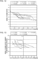
- Fig. 12 is a first graph illustrating the signal to noise ratios of various array sensors.
- the horizontal axis is the aperture/(wavelength ⁇ number of microphones) (1/pieces )
- the vertical axis is the signal to noise ratio.
- Grating lobes are more likely to occur as the aperture increases, while they are less likely to occur when the wavelength of the sound wave becomes longer or the number of microphones 15 increases. Therefore, the signal to noise ratios of the individual array sensors are compared using a value obtained by dividing the aperture (diameter of the outer circle) by the wavelength and the number of microphones on the horizontal axis.
- the number n on the left indicates the number of vertices of an inner concyclic regular polygon
- the number m on the right indicates the number of vertices of an outer concyclic regular polygon. That is, 10-11-gons mean an array sensor in which the microphones 15 are arranged at the vertices of an outer concyclic regular decagon and an outer concyclic regular hendecagon.
- the diameter of the inner circle is set to 7 mm or more, where the signal to noise ratio is greatest.
- the method of determining the diameter of the inner circle is the same for Figs. 12 to 15
- the method of displaying each array sensor is the same for Figs. 12 to 17 .
- the signal to noise ratio of an array sensor in which the number of vertices of the outer concyclic regular polygon is an odd number is higher than the signal to noise ratio of an array sensor in which the number of vertices of the outer concyclic regular polygon is an even number. Since the parameters of simulation are the same for each array sensor, a high signal to noise ratio indicates that the occurrence of grating lobes is suppressed. From the results illustrated in Fig.
- the array sensor used in the device for determining sound source direction 10 it is preferable to use an array sensor in which the number of vertices of the outer concyclic regular polygon is an odd number, and it has accordingly been confirmed that the occurrence of grating lobes is suppressed.
- the microphones 15 are provided at the vertices of three or more concyclic polygons, it is only necessary that the number of vertices of the outermost concyclic polygon be an odd number.
- Fig. 13 is a second graph illustrating the signal to noise ratios of various array sensors.
- the horizontal axis in Fig. 13 is the aperture/(wavelength ⁇ number of microphones) (1/ peaces ), and the vertical axis is the signal to noise ratio /number of microphones (1/peaces ).
- the ratio of the signal to noise ratio/number of microphones decreases as the number of microphones 15 in each array sensor increases. In particular, when the number of microphones 15 increases from 24 (11-13-gons) to 28 (13-15-gons), the ratio of the signal to noise ratio /number of microphones decreases significantly. This indicates that, even if the number of microphones is increased beyond 24, the effect of increasing the signal to noise ratio by increasing the number of microphones is small, and from this, it can be seen that the number of microphones in the array sensor is preferably 24 or less.
- the aperture of the outer concyclic regular polygon As illustrated in Fig. 13 , as the aperture of the outer concyclic regular polygon widens, the value of the signal to noise ratio /number of microphones decreases. Moreover, when the aperture of the outer concyclic regular polygon is widened, the range of appearance of grating lobes gradually expands; and it is thus preferable that the aperture of the outer concyclic regular polygon be 0.5 ⁇ n or less ( ⁇ : wavelength of the sound wave, and n: number of all the microphones). At the same time, as described above, it is effective to increase the aperture in order to enhance directivity. For this reason, it can be said that the aperture of the concyclic regular polygon is more preferably 0.5 ⁇ n.
- a signal to noise ratio of 1.7 or more in the case of aperture/wavelength 3.8 (directional FWHM: 15°) is used as a determination criterion for securing a certain signal to noise ratio while securing an aperture of a certain size. In this way, the minimum number of microphones 15 satisfying the determination criterion has been confirmed.
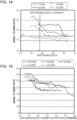
- Fig. 14 is a third graph illustrating the signal to noise ratios of various array sensors.
- the horizontal axis in Fig. 14 is the aperture/wavelength, and the vertical axis is the signal to noise ratio.
- an array sensor with 4-5-gons satisfies the above determination criterion, but an array sensor with 3-5-gons does not satisfy the above determination criterion. From this result, it has been confirmed that the number of microphones 15 included in the array sensor is preferably 9 or more.
- Fig. 15 is a fourth graph illustrating the signal to noise ratios of various array sensors.
- the horizontal axis in Fig. 15 is the aperture/(wavelength ⁇ number of microphones) (1/pieces ), and the vertical axis is the signal to noise ratio.
- the signal to noise ratio of an array sensor with 8-7-gons and the signal to noise ratio of an array sensor with 8-9-gons are almost equivalent.
- the signal to noise ratio in the case of 9-10-gons is lower than the signal to noise ratio in the case of 10-9-gons, but the decrease amount is almost equivalent to the decrease amount due to the fact that the outer side is a regular polygon with an odd number of vertices as confirmed in Fig. 12 .
- the signal to noise ratio in the case of 7-8-gons is lower than the signal to noise ratio in the case of 8-7-gons, but the decrease amount is almost equivalent to the decrease amount due to the fact that the outer side is a regular polygon with an odd number of vertices as confirmed in Fig. 12 . From these results, it has been confirmed that the number of vertices of the outer concyclic regular polygon need not be greater than the number of vertices of the inner circle, and that the number of vertices of the inner concyclic polygon may be greater than the number of vertices of the outer concyclic polygon.
- FIG. 16 is a diagram illustrating the signal to noise ratios of 7-9-gonal array sensors in which the diameter of the circumscribed circle (hereinafter may be described as the "outer circle) of an outer concyclic regular nonagon and the diameter of the circumscribed circle (hereinafter may be described as the “inner circle”) of an inner concyclic regular heptagon are changed.
- the horizontal axis in Fig. 16 is the diameter of the outer circle/wavelength, and the vertical axis is the diameter of the inner circle/wavelength.
- the parameters of simulation conducted for obtaining Figs. 16 to 18 are the same as those of Fig. 12 .
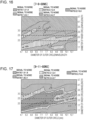
- Fig. 17 is a diagram illustrating the signal to noise ratios of 9-11-gonal array sensors in which the diameter of the outer circle and the diameter of the inner circle are changed.
- Fig. 18 is a diagram illustrating the signal to noise ratios of 6-7-gonal array sensors in which the diameter of the outer circle and the diameter of the inner circle are changed.
- the horizontal axis is the diameter of the outer circle/wavelength
- the vertical axis is the diameter of the inner circle/wavelength.
- the signal to noise ratio is enhanced by setting the diameter of the inner circle/wavelength to 3.0 or less, that is, by setting the diameter of the inner circle to 3 ⁇ or less ( ⁇ : wavelength of the sound wave). It can be seen that, by setting the diameter of the inner circle/wavelength to 2.5 or less, the sound source intensity is enhanced more, and, by setting the diameter of the inner circle/wavelength to 2.0, signal to noise ratio is enhanced further. From these results, it can be seen that the diameter of the inner circle/wavelength is preferably 3.0 or less, more preferably 2.5 or less, and further preferably 2.0.
- the diameter of the inner circle when the diameter of the inner circle is less than 7 mm, it may be difficult to arrange the microphones 15 and the camera 12; and it is thus preferable that the diameter of the inner circle be 7 mm or more.
- the diameter of the circumscribed circle of the innermost concyclic polygon may be 3.0 ⁇ or less.
- the microphones 15 are provided at the vertices of two concyclic polygons that are on same plane and that have the same center and are arranged so as to be non-rotationally symmetric as a whole array sensor, it is preferable to arrange the microphones 15 as described in 1 to 5 below, and it has accordingly been confirmed that the occurrence of grating lobes can be suppressed.
Landscapes
- Engineering & Computer Science (AREA)
- Physics & Mathematics (AREA)
- Signal Processing (AREA)
- Acoustics & Sound (AREA)
- Health & Medical Sciences (AREA)
- Otolaryngology (AREA)
- Remote Sensing (AREA)
- Radar, Positioning & Navigation (AREA)
- General Physics & Mathematics (AREA)
- Computational Linguistics (AREA)
- Audiology, Speech & Language Pathology (AREA)
- Human Computer Interaction (AREA)
- Multimedia (AREA)
- Circuit For Audible Band Transducer (AREA)
- Measurement Of Velocity Or Position Using Acoustic Or Ultrasonic Waves (AREA)
- Obtaining Desirable Characteristics In Audible-Bandwidth Transducers (AREA)
Applications Claiming Priority (2)
| Application Number | Priority Date | Filing Date | Title |
|---|---|---|---|
| PCT/JP2020/040905 WO2022091370A1 (fr) | 2020-10-30 | 2020-10-30 | Dispositif de localisation de l'azimut d'une source sonore |
| PCT/JP2021/033022 WO2022091591A1 (fr) | 2020-10-30 | 2021-09-08 | Dispositif d'orientation azimutale de la source sonore |
Publications (2)
| Publication Number | Publication Date |
|---|---|
| EP4199534A1 true EP4199534A1 (fr) | 2023-06-21 |
| EP4199534A4 EP4199534A4 (fr) | 2024-01-31 |
Family
ID=81382261
Family Applications (1)
| Application Number | Title | Priority Date | Filing Date |
|---|---|---|---|
| EP21885710.0A Pending EP4199534A4 (fr) | 2020-10-30 | 2021-09-08 | Dispositif d'orientation azimutale de la source sonore |
Country Status (6)
| Country | Link |
|---|---|
| US (1) | US12411199B2 (fr) |
| EP (1) | EP4199534A4 (fr) |
| JP (1) | JP7220804B2 (fr) |
| KR (1) | KR102721630B1 (fr) |
| CN (1) | CN116325792A (fr) |
| WO (2) | WO2022091370A1 (fr) |
Families Citing this family (1)
| Publication number | Priority date | Publication date | Assignee | Title |
|---|---|---|---|---|
| WO2024166569A1 (fr) * | 2023-02-09 | 2024-08-15 | ソニーグループ株式会社 | Dispositif de collecte de son |
Family Cites Families (16)
| Publication number | Priority date | Publication date | Assignee | Title |
|---|---|---|---|---|
| JPH0286397A (ja) * | 1988-09-22 | 1990-03-27 | Nippon Telegr & Teleph Corp <Ntt> | マイクロホンアレー |
| US5838284A (en) | 1996-05-17 | 1998-11-17 | The Boeing Company | Spiral-shaped array for broadband imaging |
| DK174558B1 (da) | 2002-03-15 | 2003-06-02 | Bruel & Kjaer Sound & Vibratio | Stråleformende transducer-antennesystem |
| JP2011015050A (ja) | 2009-06-30 | 2011-01-20 | Nittobo Acoustic Engineering Co Ltd | ビームフォーミング用のアレイ、及びそれを用いた音源探査測定システム |
| US9973848B2 (en) * | 2011-06-21 | 2018-05-15 | Amazon Technologies, Inc. | Signal-enhancing beamforming in an augmented reality environment |
| JP6061693B2 (ja) * | 2013-01-18 | 2017-01-18 | 株式会社日立パワーソリューションズ | 異常診断装置およびこれを用いた異常診断方法 |
| EP2992687B1 (fr) * | 2013-04-29 | 2018-06-06 | University Of Surrey | Ensemble de microphones pour séparation de source acoustique |
| CN107155344A (zh) * | 2014-07-23 | 2017-09-12 | 澳大利亚国立大学 | 平面传感器阵列 |
| JP6202277B2 (ja) | 2014-08-05 | 2017-09-27 | パナソニックIpマネジメント株式会社 | 音声処理システム及び音声処理方法 |
| US9565493B2 (en) | 2015-04-30 | 2017-02-07 | Shure Acquisition Holdings, Inc. | Array microphone system and method of assembling the same |
| CN109642937B (zh) * | 2016-09-23 | 2023-04-18 | 杰富意钢铁株式会社 | 超声波源的方位标定装置及重合图像的分析方法 |
| US9930448B1 (en) * | 2016-11-09 | 2018-03-27 | Northwestern Polytechnical University | Concentric circular differential microphone arrays and associated beamforming |
| CN106548783B (zh) | 2016-12-09 | 2020-07-14 | 西安Tcl软件开发有限公司 | 语音增强方法、装置及智能音箱、智能电视 |
| GB201814988D0 (en) | 2018-09-14 | 2018-10-31 | Squarehead Tech As | Microphone Arrays |
| KR102138117B1 (ko) | 2018-12-12 | 2020-07-27 | 한국표준과학연구원 | 휴대용 고해상도 초음파 카메라 |
| JP2021072575A (ja) * | 2019-10-31 | 2021-05-06 | パナソニックIpマネジメント株式会社 | 音源表示システム及び音源表示装置 |
-
2020
- 2020-10-30 WO PCT/JP2020/040905 patent/WO2022091370A1/fr not_active Ceased
-
2021
- 2021-09-08 EP EP21885710.0A patent/EP4199534A4/fr active Pending
- 2021-09-08 JP JP2021557264A patent/JP7220804B2/ja active Active
- 2021-09-08 WO PCT/JP2021/033022 patent/WO2022091591A1/fr not_active Ceased
- 2021-09-08 CN CN202180071562.3A patent/CN116325792A/zh active Pending
- 2021-09-08 US US18/033,981 patent/US12411199B2/en active Active
- 2021-09-08 KR KR1020237013921A patent/KR102721630B1/ko active Active
Also Published As
| Publication number | Publication date |
|---|---|
| EP4199534A4 (fr) | 2024-01-31 |
| JP7220804B2 (ja) | 2023-02-10 |
| KR102721630B1 (ko) | 2024-10-23 |
| US12411199B2 (en) | 2025-09-09 |
| US20230393228A1 (en) | 2023-12-07 |
| KR20230074242A (ko) | 2023-05-26 |
| JPWO2022091591A1 (fr) | 2022-05-05 |
| WO2022091591A1 (fr) | 2022-05-05 |
| WO2022091370A1 (fr) | 2022-05-05 |
| CN116325792A (zh) | 2023-06-23 |
Similar Documents
| Publication | Publication Date | Title |
|---|---|---|
| US9949033B2 (en) | Planar sensor array | |
| EP3517991A1 (fr) | Dispositif d'orientation d'azimut de source d'ondes ultrasonores, et procédé d'analyse d'image superposée | |
| JP2016042036A5 (fr) | ||
| JP2017523441A (ja) | 干渉計 | |
| US20190361105A1 (en) | Method and apparatus for determining object direction | |
| CN105890762A (zh) | 小型分光仪 | |
| US12411199B2 (en) | Device for determining sound source direction | |
| JP2015219138A (ja) | 音源探査装置、音源探査方法、および音源探査プログラム | |
| CN115342919A (zh) | 基于声光可调谐滤波器的实时高光谱偏振成像系统及方法 | |
| US20090326870A1 (en) | System and characterization of noise sources using acoustic phased arrays and time series correlations | |
| Ando et al. | Partial differential equation-based localization of a monopole source from a circular array | |
| US20180038934A1 (en) | Discrimination of signal angle of arrival using at least two antennas | |
| JP2011179896A (ja) | ビーム合成装置、ビーム合成方法及び円筒アレイ受信システム | |
| JP2007163321A (ja) | 電波到来方向測定装置およびそのためのアレーアンテナ装置 | |
| US20010049709A1 (en) | Fringe analysis method using fourier transform | |
| KR101815584B1 (ko) | 음원의 위치를 정밀 추정하기 위한 3차원 음향 인텐시티 탐촉장치의 편향오차 보상방법 | |
| CN120294748A (zh) | 一种涡旋电磁波雷达多径虚像抑制方法及系统 | |
| Vaddi et al. | A VLA–GMRT look at 11 powerful FR ii quasars | |
| JP7717182B2 (ja) | 音波遮蔽フードを備えた音源方位標定装置 | |
| CN107356234B (zh) | 一种基于光栅的空间姿态无源测头 | |
| CN112698169B (zh) | 一种电晕放电定位方法、装置、电子设备及存储介质 | |
| US9274209B2 (en) | Positioning | |
| WO2015091391A1 (fr) | Calcul de section efficace de radar | |
| JP6100655B2 (ja) | 音源探査装置 | |
| Jung et al. | Double tetrahedral intensity probes for reducing the spatial bias error of source localization |
Legal Events
| Date | Code | Title | Description |
|---|---|---|---|
| STAA | Information on the status of an ep patent application or granted ep patent |
Free format text: STATUS: THE INTERNATIONAL PUBLICATION HAS BEEN MADE |
|
| PUAI | Public reference made under article 153(3) epc to a published international application that has entered the european phase |
Free format text: ORIGINAL CODE: 0009012 |
|
| STAA | Information on the status of an ep patent application or granted ep patent |
Free format text: STATUS: REQUEST FOR EXAMINATION WAS MADE |
|
| 17P | Request for examination filed |
Effective date: 20230316 |
|
| AK | Designated contracting states |
Kind code of ref document: A1 Designated state(s): AL AT BE BG CH CY CZ DE DK EE ES FI FR GB GR HR HU IE IS IT LI LT LU LV MC MK MT NL NO PL PT RO RS SE SI SK SM TR |
|
| REG | Reference to a national code |
Ref country code: DE Ref legal event code: R079 Free format text: PREVIOUS MAIN CLASS: H04R0001400000 Ipc: G01S0003808000 |
|
| A4 | Supplementary search report drawn up and despatched |
Effective date: 20240105 |
|
| RIC1 | Information provided on ipc code assigned before grant |
Ipc: H04R 3/00 20060101ALI20231222BHEP Ipc: H04R 1/40 20060101ALI20231222BHEP Ipc: G01S 3/808 20060101AFI20231222BHEP |
|
| DAV | Request for validation of the european patent (deleted) | ||
| DAX | Request for extension of the european patent (deleted) | ||
| STAA | Information on the status of an ep patent application or granted ep patent |
Free format text: STATUS: EXAMINATION IS IN PROGRESS |
|
| 17Q | First examination report despatched |
Effective date: 20251022 |