EP4199535A1 - Verfahren zum auffinden einer audioausgabevorrichtung unter verwendung einer stromversorgungsvorrichtung und stromversorgungsvorrichtung dafür - Google Patents
Verfahren zum auffinden einer audioausgabevorrichtung unter verwendung einer stromversorgungsvorrichtung und stromversorgungsvorrichtung dafür Download PDFInfo
- Publication number
- EP4199535A1 EP4199535A1 EP21915712.0A EP21915712A EP4199535A1 EP 4199535 A1 EP4199535 A1 EP 4199535A1 EP 21915712 A EP21915712 A EP 21915712A EP 4199535 A1 EP4199535 A1 EP 4199535A1
- Authority
- EP
- European Patent Office
- Prior art keywords
- audio output
- output device
- power supply
- electronic device
- signal
- Prior art date
- Legal status (The legal status is an assumption and is not a legal conclusion. Google has not performed a legal analysis and makes no representation as to the accuracy of the status listed.)
- Pending
Links
Images








Classifications
-
- H—ELECTRICITY
- H04—ELECTRIC COMMUNICATION TECHNIQUE
- H04R—LOUDSPEAKERS, MICROPHONES, GRAMOPHONE PICK-UPS OR LIKE ACOUSTIC ELECTROMECHANICAL TRANSDUCERS; ELECTRIC HEARING AIDS; PUBLIC ADDRESS SYSTEMS
- H04R3/00—Circuits for transducers
- H04R3/12—Circuits for transducers for distributing signals to two or more loudspeakers
-
- H—ELECTRICITY
- H04—ELECTRIC COMMUNICATION TECHNIQUE
- H04R—LOUDSPEAKERS, MICROPHONES, GRAMOPHONE PICK-UPS OR LIKE ACOUSTIC ELECTROMECHANICAL TRANSDUCERS; ELECTRIC HEARING AIDS; PUBLIC ADDRESS SYSTEMS
- H04R1/00—Details of transducers, loudspeakers or microphones
- H04R1/10—Earpieces; Attachments therefor ; Earphones; Monophonic headphones
- H04R1/1016—Earpieces of the intra-aural type
-
- G—PHYSICS
- G08—SIGNALLING
- G08B—SIGNALLING SYSTEMS, e.g. PERSONAL CALLING SYSTEMS; ORDER TELEGRAPHS; ALARM SYSTEMS
- G08B7/00—Signalling systems according to two or more of groups G08B3/00 - G08B6/00
- G08B7/06—Signalling systems according to two or more of groups G08B3/00 - G08B6/00 using electric transmission, e.g. involving audible and visible signalling through the use of sound and light sources
-
- H—ELECTRICITY
- H04—ELECTRIC COMMUNICATION TECHNIQUE
- H04R—LOUDSPEAKERS, MICROPHONES, GRAMOPHONE PICK-UPS OR LIKE ACOUSTIC ELECTROMECHANICAL TRANSDUCERS; ELECTRIC HEARING AIDS; PUBLIC ADDRESS SYSTEMS
- H04R1/00—Details of transducers, loudspeakers or microphones
- H04R1/10—Earpieces; Attachments therefor ; Earphones; Monophonic headphones
- H04R1/1025—Accumulators specially adapted for earpieces; Arrangements specially adapted for charging thereof
-
- H—ELECTRICITY
- H04—ELECTRIC COMMUNICATION TECHNIQUE
- H04R—LOUDSPEAKERS, MICROPHONES, GRAMOPHONE PICK-UPS OR LIKE ACOUSTIC ELECTROMECHANICAL TRANSDUCERS; ELECTRIC HEARING AIDS; PUBLIC ADDRESS SYSTEMS
- H04R1/00—Details of transducers, loudspeakers or microphones
- H04R1/10—Earpieces; Attachments therefor ; Earphones; Monophonic headphones
- H04R1/1041—Mechanical or electronic switches, or control elements
-
- H—ELECTRICITY
- H04—ELECTRIC COMMUNICATION TECHNIQUE
- H04R—LOUDSPEAKERS, MICROPHONES, GRAMOPHONE PICK-UPS OR LIKE ACOUSTIC ELECTROMECHANICAL TRANSDUCERS; ELECTRIC HEARING AIDS; PUBLIC ADDRESS SYSTEMS
- H04R5/00—Stereophonic arrangements
- H04R5/04—Circuit arrangements, e.g. for selective connection of amplifier inputs/outputs to loudspeakers, for loudspeaker detection, or for adaptation of settings to personal preferences or hearing impairments
-
- H—ELECTRICITY
- H04—ELECTRIC COMMUNICATION TECHNIQUE
- H04W—WIRELESS COMMUNICATION NETWORKS
- H04W4/00—Services specially adapted for wireless communication networks; Facilities therefor
- H04W4/80—Services using short range communication, e.g. near-field communication [NFC], radio-frequency identification [RFID] or low energy communication
-
- H—ELECTRICITY
- H04—ELECTRIC COMMUNICATION TECHNIQUE
- H04W—WIRELESS COMMUNICATION NETWORKS
- H04W48/00—Access restriction; Network selection; Access point selection
- H04W48/16—Discovering, processing access restriction or access information
-
- H—ELECTRICITY
- H04—ELECTRIC COMMUNICATION TECHNIQUE
- H04R—LOUDSPEAKERS, MICROPHONES, GRAMOPHONE PICK-UPS OR LIKE ACOUSTIC ELECTROMECHANICAL TRANSDUCERS; ELECTRIC HEARING AIDS; PUBLIC ADDRESS SYSTEMS
- H04R2420/00—Details of connection covered by H04R, not provided for in its groups
- H04R2420/03—Connection circuits to selectively connect loudspeakers or headphones to amplifiers
-
- H—ELECTRICITY
- H04—ELECTRIC COMMUNICATION TECHNIQUE
- H04R—LOUDSPEAKERS, MICROPHONES, GRAMOPHONE PICK-UPS OR LIKE ACOUSTIC ELECTROMECHANICAL TRANSDUCERS; ELECTRIC HEARING AIDS; PUBLIC ADDRESS SYSTEMS
- H04R2420/00—Details of connection covered by H04R, not provided for in its groups
- H04R2420/05—Detection of connection of loudspeakers or headphones to amplifiers
-
- H—ELECTRICITY
- H04—ELECTRIC COMMUNICATION TECHNIQUE
- H04R—LOUDSPEAKERS, MICROPHONES, GRAMOPHONE PICK-UPS OR LIKE ACOUSTIC ELECTROMECHANICAL TRANSDUCERS; ELECTRIC HEARING AIDS; PUBLIC ADDRESS SYSTEMS
- H04R2420/00—Details of connection covered by H04R, not provided for in its groups
- H04R2420/07—Applications of wireless loudspeakers or wireless microphones
-
- H—ELECTRICITY
- H04—ELECTRIC COMMUNICATION TECHNIQUE
- H04R—LOUDSPEAKERS, MICROPHONES, GRAMOPHONE PICK-UPS OR LIKE ACOUSTIC ELECTROMECHANICAL TRANSDUCERS; ELECTRIC HEARING AIDS; PUBLIC ADDRESS SYSTEMS
- H04R2430/00—Signal processing covered by H04R, not provided for in its groups
- H04R2430/01—Aspects of volume control, not necessarily automatic, in sound systems
-
- H—ELECTRICITY
- H04—ELECTRIC COMMUNICATION TECHNIQUE
- H04R—LOUDSPEAKERS, MICROPHONES, GRAMOPHONE PICK-UPS OR LIKE ACOUSTIC ELECTROMECHANICAL TRANSDUCERS; ELECTRIC HEARING AIDS; PUBLIC ADDRESS SYSTEMS
- H04R29/00—Monitoring arrangements; Testing arrangements
- H04R29/008—Visual indication of individual signal levels
-
- Y—GENERAL TAGGING OF NEW TECHNOLOGICAL DEVELOPMENTS; GENERAL TAGGING OF CROSS-SECTIONAL TECHNOLOGIES SPANNING OVER SEVERAL SECTIONS OF THE IPC; TECHNICAL SUBJECTS COVERED BY FORMER USPC CROSS-REFERENCE ART COLLECTIONS [XRACs] AND DIGESTS
- Y02—TECHNOLOGIES OR APPLICATIONS FOR MITIGATION OR ADAPTATION AGAINST CLIMATE CHANGE
- Y02D—CLIMATE CHANGE MITIGATION TECHNOLOGIES IN INFORMATION AND COMMUNICATION TECHNOLOGIES [ICT], I.E. INFORMATION AND COMMUNICATION TECHNOLOGIES AIMING AT THE REDUCTION OF THEIR OWN ENERGY USE
- Y02D30/00—Reducing energy consumption in communication networks
- Y02D30/70—Reducing energy consumption in communication networks in wireless communication networks
Definitions
- Various embodiments disclosed in the present document relate to an audio output device and a power supply device, and also, to a method for finding a position of an audio output device by using a power supply device in an external electronic device.
- Bluetooth earphone Since the Bluetooth earphone provides activity and convenience to a user compared to an existing wired earphone, many users are increasingly using the Bluetooth earphones.
- the Bluetooth earphone of the cord-free type from which a wire of the earphone is completely removed may include a separate battery therein, and a separate charging case may be provided to charge and store the battery.
- a Bluetooth earphone may connect Bluetooth communication with an external electronic device to perform various functions (for example, sound output) loaded therein when the Bluetooth earphone is worn on a user's body.
- the Bluetooth earphone may determine that it is not in use when the Bluetooth earphone is received in a power supply device (for example, a charging case or a charging accessory), and may disconnect the Bluetooth communication from the external electronic device.
- a power supply device for example, a charging case or a charging accessory
- Bluetooth earphones are getting smaller, it may be difficult to find where a Bluetooth earphone is lost or placed, and a function of finding the position of a Bluetooth earphone may be provided through Bluetooth communication connection with an external electronic device.
- the external electronic device may request an alarm (for example, a notification sound, vibration, or LED lighting, etc.) from a Bluetooth earphone through Bluetooth communication.
- the user may not use the function of finding the Bluetooth earphone in an external device since Bluetooth communication between the Bluetooth earphone and the external electronic device is disconnected and the power supply device is not able to wirelessly communicate with the external electronic device.
- the Bluetooth earphone is not received in the power supply device but Bluetooth communication between the Bluetooth earphone and the external electronic device is disconnected, there is no way of finding the lost Bluetooth earphone in the external electronic device.
- Various embodiments disclosed in the present document may provide an external electronic device and a power supply device which may find a position of a Bluetooth earphone by using the power supply device when Bluetooth communication between the Bluetooth earphone and the external electronic device is disconnected.
- An electronic device may include: a wireless communication circuit; a power management circuit; and a control circuit electrically connected with the wireless communication circuit and the power management circuit, and the control circuit may: in a state where the electronic device connects a first communication with a first audio output device by using the wireless communication circuit, or is electrically connected with the first audio output device by using the power management circuit, operate in a connection standby mode or in an advertise mode by using a first wireless communication address of the first audio output device; receive a signal for finding the first audio output device from an external electronic device, based on the first wireless communication address; and, in response to the signal for finding the first audio output device being received, transmit a signal for letting the first audio output device output a notification (or alarm) (or a signal indicating the first audio output device output a notification, a signal instructing the first audio output device to output a notification) to the first audio output device through the first communication, or transmit the signal to the first audio output device through the electrical connection.
- a notification or alarm
- a method for finding a position of an audio output device by using an electronic device may include: in a state where the electronic device connects a first communication with a first audio output device or is electrically connected with the first audio output device, operating in a connection standby mode or in an advertise mode by using a first wireless communication address of the first audio output device; receiving a signal for finding the first audio output device from an external electronic device, based on the first wireless communication address; and, in response to the signal for finding the first audio output device being received, transmitting a signal for letting the first audio output device output a notification (or an alarm) to the first audio output device through the first communication, or transmitting the signal to the first audio output device through the electrical connection.
- an audio output device may include: an audio processing circuit; a power management circuit; a wireless communication circuit configured to establish a communication connection by using a wireless communication address; and a control circuit electrically connected with the audio processing circuit, the power management circuit, and the wireless communication circuit, and the control circuit may be configured to: establish a first communication connection with a power supply device by using the wireless communication circuit, or an electrical connection with the power supply device by using the power management circuit; receive, from the power supply device, a signal for finding at least one audio output device including the audio output device, the signal being received by the power supply device from an external electronic device; and, in response to the signal for finding the at least one audio output device being received, control the audio processing circuit to output a notification (or an alarm).
- the power supply device may operate in a connection standby mode or in an advertise mode by using a wireless communication address of the audio output device, so that, even when the external electronic device does not know the wireless communication address of the power supply device, the power supply device may receive a signal for finding the audio output device.
- the audio output device may output an alarm for informing its own position by receiving a signal for finding the audio output device, which is received by the power supply device from the external electronic device, from the power supply device.
- FIGS. 1 through 17 discussed below, and the various embodiments used to describe the principles of the present disclosure in this patent document are by way of illustration only and should not be construed in any way to limit the scope of the disclosure. Those skilled in the art will understand that the principles of the present disclosure may be implemented in any suitably arranged system or device.
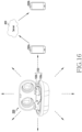
- FIG. 1 illustrates an audio output device 100, an electronic device 200 (or a case device, a power supply device, hereinafter, referred to as a "power supply device") capable of receiving the audio output device 100, and an external electronic device 300.
- the audio output device 100 may be received and stored in the power supply device 200 when the audio output device 100 is not in use.
- the audio output device 100 may be worn on a part of a user's body (for example, ears).
- the audio output device 100 may be configured in pairs to be worn on both ears of a user.
- the audio output device 100 may include a first audio output device 100a to be worn on the user's right ear, and a second audio output device 100b to be worn on the user's left ear.
- the power supply device 200 may include a first receiver 202 to have the first audio output device 100a disposed therein, and a second receiver 204 to have the second audio output device 100b disposed therein.
- a first interface 206 including at least one terminal may be disposed on a bottom surface of the first receiver 202
- a second interface 208 including at least one terminal may be disposed on a bottom surface of the second receiver 204.
- the first interface 206 and the second interface 208 may include a pogo pin.
- the first interface 206 and the second interface 208 may include at least one of a charging power terminal, a ground (GND) terminal, a detect terminal, or a data communication terminal. At least one terminal of the first interface 206 and the second interface 208 may be disposed to physically or electrically come into contact with at least one terminal of the audio output device 100 when the audio output device 100 is received in the power supply device 200.
- At least one terminal of the first interface 206 and the second interface 208 may perform at least one function of functions of the charging power terminal, the detect terminal, and the data communication terminal.
- one terminal included in the first interface 206 may detect that the first audio output device 100a is disposed in the first receiver 202, may charge the first audio output device 100a, and/or may perform data communication with the first audio output device 100a.
- one terminal included in the second interface 208 may detect that the second audio output device 100b is disposed in the second receiver 204, may charge the second audio output device 100b, and/or may perform data communication with the second audio output device 100b.
- the power supply device 200 may include at least one light emitting diode (LED) display lamp 210.
- the LED display lamp 210 may output a signal when the first audio output device 100a or the second audio output device 100b is disposed in at least one receiver of the first receiver 202 or the second receiver 204.
- the LED display lamp 210 may output a signal (for example, green light or red light) indicating a charging state (for example, a fully charged state or an intermediate charged state) of the first audio output device 100a.
- the power supply device 200 may also output a vibration signal indicating a charging state (for example, an initial charging state or a fully charged state) of the first audio output device 100a and/or the second audio output device 100b.
- a charging state for example, an initial charging state or a fully charged state
- the first audio output device 100a may receive power from the power supply device 200 through a first interface 102.
- the second audio output device 100b may receive power from the power supply device 200 through a second interface 104.
- the first audio output device 100a may transmit data to the power supply device 200 through the first interface 102, and the second audio output device 100b may transmit data to the power supply device 200 through the second interface 104.
- the first audio output device 100a may transmit information including battery remaining capacity information of the first audio output device 100a to the power supply device 200.
- the first audio output device 100a may exchange data with the power supply device 200 through the first interface 102
- the second audio output device 100b may exchange data with the power supply device 200 through the second interface 104.
- the first audio output device 100a may receive, from the power supply device 200, information including battery remaining capacity information of the second audio output device 100b and/or battery remaining capacity information of the power supply device 200.
- the second audio output device 100b may receive, from the power supply device 200, information including battery remaining capacity information of the first audio output device 100a and/or battery remaining capacity information of the power supply device 200.
- the first audio output device 100a and/or the second audio output device 100b may exchange information including each other's battery remaining capacity information by using communication connected between the first audio output device 100a and the second audio output device 100b.
- the audio output device 100 may output audio when the audio output device is worn on a user's body.
- at least one of the first audio output device 100a and the second audio output device 100b may output audio by exchanging wireless data with the external electronic device 300.
- a path for exchanging the wireless data may include at least one of a path for a Bluetooth communication scheme, a path for a Bluetooth low energy (BLE) communication scheme, a path for a wireless fidelity (Wi-Fi) direct communication scheme, and a path for a mobile communication scheme (for example, cellular communication, sidelink).
- BLE Bluetooth low energy
- Wi-Fi wireless fidelity
- a mobile communication scheme for example, cellular communication, sidelink.
- the audio output device 100 and the external electronic device 300 may identify each other's wireless communication address, and may perform communication.
- only one of the pair of audio output devices 100a, 100b may generate the communication path with the external electronic device 300.
- the external electronic device 300 may be connected with the first audio output device 100a out of the pair of audio output devices 100a, 100b.
- the external electronic device 300 or the first audio output device 100a may provide information on the communication path to the second audio output device 100b in order for the second audio output device 100b to output the audio.
- the second audio output device 100b may receive or sniff data which is transmitted to the first audio output device 100a, based on the information on the communication path, and may output the audio.
- the first audio output device 100a connected with the external electronic device 300 may be referred to as a master device or a main audio output device
- the second audio output device 100b that is not connected with the external electronic device 300 may be referred to as a slave device or a sub audio output device.
- the first audio output device 100a and/or the second audio output device 100b may use a true wireless stereo (TWS) (for example, a relay method, a sniffing method), TWS+, or audio over BLE (AoBLE) communication method with the external electronic device 300.
- TWS true wireless stereo
- AoBLE audio over BLE
- the first audio output device 100a and the second audio output device 100b may connect communication therebetween, and may collect information, and any one of the first audio output device 100a and the second audio output device 100b may connect communication with the external electronic device 300 and may transmit the collected information.
- the TWS+ or AoBLE communication method the first audio output device 100a and the second audio output device 100b may connect communication with the external electronic device 300, respectively, and may transmit information.
- the external electronic device 300 when the first audio output device 100a and/or the second audio output device 100b is communicatively coupled with the external electronic device 300, the external electronic device 300 may be a master device, and the first audio output device 100a and/or the second audio output device 100b may be a slave device.
- the first audio output device 100a and/or the second audio output device 100b when communication is connected between the first audio output device 100a and the second audio output device 100b, one of the first audio output device 100a and/or the second audio output device 100b may be a master device, and the other one may be a slave device.
- the roles (or settings) of the master device and the slave device of the first audio output device 100a and the second audio output device 100b may be changed based on a designated condition.
- the first audio output device 100a and the second audio output device 100b are removed from the power supply device 200 simultaneously, the first audio output device 100a that may be worn on the right may correspond to a master device, and the second audio output device 100b that may be worn on the left may correspond to a slave device.
- the second audio output device 100b may correspond to a master device.
- the roles of the master device and the slave device of the first audio output device 100a and the second audio output device 100b may be fixed.
- the roles of the master device and the slave device of the first audio output device 100a and the second audio output device 100b may be designated by a designer, or may not be changeable after being fixed.
- a device that corresponds to a master device among the audio output devices 100 may perform a role of transmitting data generated at the audio output device 100 to the external electronic device 300.
- the master device may perform a role of transmitting a response signal to data transmitted from the external electronic device 300 to the audio output device 100, transmitting data (for example, audio data acquired through a microphone or a sensor value acquired through a sensor) generated at the audio output device 100, and/or transmitting state information (for example, a remaining capacity of a battery) of the audio output device 100.
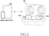
- FIG. 2 illustrates a view of the audio output device 100 received in the power supply device 200, and the external electronic device 300 according to an embodiment.
- the power supply device 200 may have a hinged structure, and the audio output device 100 may be received in a recess (for example, the first receiver 202 or the second receiver 204 of FIG. 1 ) formed in the power supply device 200 when the power supply device 200 is opened.
- the audio output device 100 may be received by having at least part thereof seated in the recess of the power supply device 200.
- the audio output device 100 may include a sensed member corresponding to a sensor of the power supply device 200 although it is not illustrated.
- the power supply device 200 may include a hall sensor (or a hall integrated circuit (IC)) and the audio output device 100 may include a magnet.
- the hall sensor of the power supply device 200 may recognize that the audio output device 100 is received in the power supply device 200, and may transmit the recognized state to the audio output device 100.
- the audio output device 100 may include a hall sensor, and the audio output device 100 may directly detect that a lid of the power supply device 200 is closed by using the hall sensor.
- the power supply device 200 may detect that the audio output device 100 is received in the power supply device 200 and the lid of the power supply device 200 is closed, and may control the audio output device 100, and the audio output device 100 may detect that the lid of the power supply device 200 is closed by using the hall sensor, and may control itself.
- the power supply device 200 may supply power to the audio output device 100 through an interface (for example, the first interface 206 and/or the second interface 208).
- the audio output device 100 may recognize that the audio output device 100 is received in the power supply device 200, based on power being received from the power supply device 200 through an interface (for example, the first interface 102 and/or the second interface 104).
- the power supply device 200 may receive state information (for example, a remaining battery capacity) of the audio output device 100 through communication (for example, power line communication (PLC)) with the audio output device 100, and may control charging of the audio output device 100 based on the state information (for example, the remaining battery capacity) of the audio output device 100. For example, when state information (for example, a remaining battery capacity) of the first audio output device 100a and state information (for example, a remaining battery capacity) of the second audio output device 100b are different from each other by a designated threshold value or more, the power supply device 200 may control charging to make the first audio output device 100a and the second audio output device 100b have substantially the same remaining battery capacity.
- state information for example, a remaining battery capacity
- PLC power line communication
- the audio output device 100 when the audio output device 100 is received in the power supply device 200 and receives power from the power supply device 200, the audio output device 100 may disable a wireless communication circuit (or a wireless data exchange path) of the audio output device 100.
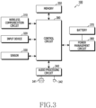
- FIG. 3 illustrates a block diagram of the audio output device 100 according to an embodiment.
- the audio output device 100 may include a plurality of electronic components disposed in an inner space thereof.
- the audio output device 100 may include a wireless communication circuit 310, an input device 320, a sensor 330, an audio processing circuit 340, a speaker 341, a microphone 342, a memory 350, a power management circuit 360, a battery 370, and a control circuit 380.
- the audio output device 100 may refer to at least one of the first audio output device 100a and the second audio output device 100b, or may refer to a device of the first audio output device 100a and the second audio output device 100b that connects communication with the external electronic device 300 (for example, a master device of the first audio output device 100a and the second audio output device 100b that connects communication with the external electronic device 300).
- the wireless communication circuit 310 may support communication of various types by using an antenna. According to an embodiment, the wireless communication circuit 310 may support reception of audio data from an external device (for example, a server, a smartphone, a PC, a personal digital assistant (PDA), or an access point) (for example, the external electronic device 300 of FIG. 1 ). According to an embodiment, the wireless communication circuit 310 may support transmission of audio data to an external device (for example, another audio output device).
- an external device for example, a server, a smartphone, a PC, a personal digital assistant (PDA), or an access point
- the wireless communication circuit 310 may support transmission of audio data to an external device (for example, another audio output device).
- the input device 320 may be configured to generate various input signals necessary for operating the audio output device 100.
- the input device 320 may include a touch pad, a touch panel, and/or a button.
- the touch pad may recognize a touch input in at least one method of capacitive, resistive, infrared and ultrasonic methods.
- the button may include a physical button and/or an optical button.
- the input device 320 may generate a user input related to power on or off of the audio output device 100. According to an embodiment, the input device 320 may generate a user input related to communication (for example, short-range communication) connection with the audio output device 100 and an external device.
- communication for example, short-range communication
- the input device 320 may generate a user input related to audio data (or audio content).
- the user input may be related to functions such as starting play of audio data, pausing, stopping, adjusting a replay speed, adjusting a replay volume or muting.
- the sensor 330 may measure physical data related to the audio output device 100 or may detect an operation state of the audio output device 100. In addition, the sensor 330 may convert the measured or detected information into an electric signal. According to an embodiment, the sensor 330 may include at least one of a proximity sensor, an acceleration sensor, a gyro sensor, a geomagnetic sensor, a magnetic sensor, a gesture sensor, a grip sensor, or a biometric sensor. According to an embodiment, the sensor 330 may detect information or a signal regarding whether the audio output device 100 is worn on user's body.
- the audio processing circuit 340 may support an audio data collecting function and may reproduce collected audio data.
- the audio processing circuit 340 may include an audio decoder and a digital-to-analogue (D/A) converter.
- the audio decoder may convert audio data stored in the memory 350 into a digital audio signal
- the D/A converter may convert the digital audio signal converted by the audio decoder into an analogue audio signal.
- the audio decoder may convert audio data received from an external device (for example, a server, a smartphone, a PC, a PDA, or an access point) through the wireless communication circuit 310 and stored in the memory 350 into a digital audio signal.
- an external device for example, a server, a smartphone, a PC, a PDA, or an access point
- the speaker 341 may output the analogue audio signal converted by the D/A converter.
- the audio processing circuit 340 may include an analogue-to-digital (A/D) converter.
- the A/D converter may convert an analogue voice signal delivered through the microphone 342 into a digital voice signal.
- the audio processing circuit 340 may reproduce various audio data set in an operating action of the audio output device 100. For example, when it is detected that the audio output device 100 is worn on ears or is separated from ears, the audio processing circuit 340 may be designed to reproduce audio data related to a corresponding effect or a sound guide. According to another embodiment, when it is detected that the audio output device 100 is coupled to another electronic device (for example, the power supply device 200) or it is detected when the audio output device 100 is separated from another electronic device, the audio processing circuit 340 may be designed to reproduce audio data related to a corresponding effect or a sound guide.
- another electronic device for example, the power supply device 200
- the audio processing circuit 340 may be designed to reproduce audio data corresponding to a corresponding effect or a sound guide. Outputting a sound effect or a sound guide may be omitted according to user settings or a designer's intention. According to an embodiment, the audio processing circuit 340 may be designed to be included in the control circuit 380.
- the memory 350 may store various operating systems necessary for operating the audio output device 100, and data or an application program corresponding to various user functions, and algorithms.
- the memory 350 may include, for example, a high-speed random access memory and/or a non-volatile memory such as one or more magnetic disk storage device, one or more optical storage devices and/or a flash memory (for example, NAND, NOR).
- the memory 350 may include a nonvolatile memory which stores nonvolatile audio data received from an external device (for example, a server, a smartphone, a PC, a PDA, or an access point).
- the memory 350 may include a volatile memory which stores volatile audio data received from an external device.
- the power management circuit 360 may efficiently manage and optimize use of power of the battery 370 in the audio output device 100.
- the control circuit 380 may transmit a signal resulting from a load to process to the power management circuit 360 according to the load.
- the power management circuit 360 may adjust power to be supplied to the control circuit 380.
- the power management circuit 360 may include a battery charging circuit. According to an embodiment, when the audio output device 100 is coupled to the power supply device 200, the power management circuit 360 may receive power from the power supply device 200 and may charge the battery 370. According to an embodiment, the power management circuit 360 may support power line communication (PLC) between the audio output device 100 and the power supply device 200, and the audio output device 100 may exchange data with the power supply device 200 through PLC.
- PLC power line communication
- the power management circuit 360 may include a wireless charging circuit.
- the wireless charging circuit may wirelessly receive power from an external device, and may charge the battery 370 by using the received power.
- the wireless charging circuit may support in-band communication between the audio output device 100 and the power supply device 200.
- the wireless charging circuit may transmit and receive data between the audio output device 100 and the power supply device 200 by using a frequency shift keying (FSK) modulation scheme and an amplitude shift keying (ASK) modulation scheme.
- FSK frequency shift keying
- ASK amplitude shift keying
- control circuit 380 may be configured to collect various data and to calculate a target output value. According to an embodiment, the control circuit 380 may support various actions based on least part of a user input from the input device 320.
- the control circuit 380 may be designed to receive audio data from an external device (for example, a server, a smartphone, a PC, a PDA, or an access point) through the wireless communication circuit 310, and to store the received audio data in the memory 350.
- the control circuit 380 may receive nonvolatile audio data (or downloaded audio data) from the external device, and may store the received nonvolatile audio data in the nonvolatile memory.
- the control circuit 380 may receive volatile audio data (or streaming audio data) from the external device, and may store the received volatile audio data in the volatile memory.
- control circuit 380 may control to reproduce audio data (for example, nonvolatile audio data or volatile audio data) stored in the memory 350 and to output the audio data through the speaker 341.
- the control circuit 380 may acquire an audio signal by decoding audio data, and may control to output the acquired audio signal through the speaker 341.
- control circuit 380 may perform various actions based on at least part of information acquired from the sensor 330. For example, the control circuit 380 may determine whether the audio output device 100 is worn on a user's body, based on information acquired from the sensor 330.
- the control circuit 380 may stop the mode or may transmit a relevant signal to the external device.
- the external device may receive the signal regarding the state in which the audio output device 100 is not worn on a user's body, and may stop transmitting the audio data to the audio output device 100.
- the external device may stop transmitting the audio data to the audio output device 100, based on the audio output device 100 disabling the wireless communication circuit 310. For example, when the audio output device 100 is received in the power supply device 200, the audio output device 100 may disable the wireless communication circuit 310, and based on this, the external device may stop transmitting the audio data to the audio output device 100.
- control circuit 380 may control the audio processing circuit 340 to reproduce audio data related to a corresponding sound effect or a sound guide in response to an alarm output request signal received from the power supply device 200 and/or the external electronic device 300.
- the audio output device 100 may further include various components according to a providing form thereof.
- specific components out of the above-described components may be excluded or may be substituted with other components according to a providing form of the audio output device 100.
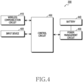
- FIG. 4 illustrates a block diagram of a power supply device 200 according to an embodiment.
- the power supply device 200 may include a plurality of electronic components disposed in an inner space thereof.
- the power supply device 200 may include a wireless communication circuit 410, an input device 420, a power management circuit 430, a battery 440, and a control circuit 450.
- Corresponding components in FIGS. 3 and 4 may perform the same function.
- the power supply device 200 may refer to a case device that receives the audio output device 100, and may refer to a case device that, when the audio output device 100 is received in the power supply device 200, charges the battery 370 of the audio output device 100.
- the wireless communication circuit 410 may support wireless communication of various types by using an antenna.
- the wireless communication circuit 410 may support Bluetooth communication and/or Bluetooth low energy (BLE) communication.
- the wireless communication circuit 410 may establish wireless communication connection with an external device (for example, the audio output device 100, the external electronic device 300), and may support exchange of data.
- an external device for example, the audio output device 100, the external electronic device 300
- the input device 420 may be configured to generate various input signals necessary for operating the power supply device 200.
- the input device 420 may include a touch pad, a touch panel, and/or a button.
- the touch pad may recognize a touch input in at least one method of capacitive, resistive, infrared, and ultrasonic methods.
- the button may include a physical button and/or an optical button.
- the input device 420 may generate a user input related to power on or off of the power supply device 200. According to an embodiment, the input device 420 may generate a user input related to communication (for example, short-range communication) connection with the power supply device 200 and an external device.
- communication for example, short-range communication
- the power management circuit 430 may efficiently manage and optimize use of power of the battery 440 in the power supply device 200.
- the control circuit 450 may transmit a signal resulting from a load to process to the power management circuit 430 according to the load.
- the power management circuit 430 may adjust power to be supplied to the control circuit 450.
- the power management circuit 430 may include a charging circuit. According to an embodiment, the power management circuit 430 may receive power from an external power source (for example, a travel adapter (TA)) and may charge the battery 440.
- an external power source for example, a travel adapter (TA)
- TA travel adapter
- the power management circuit 430 may include a wireless charging circuit.
- the wireless charging circuit may wirelessly receive power from an external device, and may charge the battery 440 by using the received power.
- the power management circuit 430 may include a power transmission circuit. According to an embodiment, when the audio output device 100 is received in the power supply device 200 and is electrically connected thereto, the power management circuit 430 may transmit power charged in the battery 440 of the power supply device 200 to the audio output device 100, and may charge the battery 370 of the audio output device 100. According to an embodiment, the power management circuit 430 may support PLC between the audio output device 100 and the power supply device 200, and the power supply device 200 may exchange data with the audio output device through PLC.
- control circuit 450 may be configured to collect various data and to calculate a target output value. According to an embodiment, the control circuit 450 may support various actions, based on at least part of a user input from the input device 420.
- control circuit 450 may control the wireless communication circuit 410 to always operate in a connection standby mode or an advertise mode, and may control the wireless communication circuit 410 to receive a communication packet from the external electronic device 300.
- the power supply device 200 may further include various components according to a providing form thereof.
- specific components out of the above-described components may be excluded or substituted with other components according to a providing form of the power supply device 200.
- the power supply device 200 may further include a sensor, an audio processing circuit, and/or a memory.
- FIG. 5 illustrates a flowchart to explain a method for finding a position of the audio output device 100 by using the power supply device 200 according to an embodiment.
- respective actions may be performed in sequence, but may not necessarily be performed in sequence.
- the order of the respective actions may be changed or at least two actions may be performed in parallel.
- Actions of FIG. 5 may be performed by the power supply device 200 of FIG. 4 .
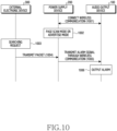
- the control circuit 450 of the power supply device 200 may perform: action 510 of operating in a connection standby mode or an advertise mode by using a wireless communication address of the audio output device 100 in a state where the power supply device 200 connects a first communication with the audio output device 100 or is electrically connected with the audio output device 100; action 520 of receiving, from the external electronic device 300, a signal for finding the audio output device 100 based on the wireless communication address of the audio output device 100; and action 530 of transmitting a signal for letting the audio output device 100 output an alarm to the audio output device 100 through the first communication, or transmitting the signal to the audio output device 100 through the electrical connection.
- action 510 of operating in a connection standby mode or an advertise mode by using a wireless communication address of the audio output device 100 in a state where the power supply device 200 connects a first communication with the audio output device 100 or is electrically connected with the audio output device 100
- the control circuit 450 of the power supply device 200 may operate in the connection standby mode or the advertise mode by using the wireless communication address of the audio output device 100.
- the power supply device 200 may be in the state where wireless communication (for example, Bluetooth communication, BLE communication) is connected with the audio output device 100, or the power supply device 200 is electrically connected with the audio output device 100. In this case, communication between the audio output device 100 and the external electronic device 300 may be disconnected.
- the power supply device 200 may connect wireless communication with the audio output device.
- the power supply device 200 may connect Bluetooth communication with the audio output device 100 by using the wireless communication circuit 410, and the control circuit 450 may transmit and receive data (for example, a battery state of the audio output device 100, information on whether the audio output device 100 is worn or not, information of the sub audio output device 100) between the audio output device 100 and the power supply device 200 through the Bluetooth communication.
- data for example, a battery state of the audio output device 100, information on whether the audio output device 100 is worn or not, information of the sub audio output device 100
- the power supply device 200 may be electrically connected with the audio output device 100.
- a terminal for example, the first interface 206, the second interface 208 of FIG. 1
- a terminal for example, the first interface 102, the second interface 104 of FIG. 1
- the control circuit 450 may perform PLC between the audio output device 100 and the power supply device 200.
- the control circuit 450 of the power supply device 200 may operate in the connection standby mode or the advertise mode by using the wireless communication address (for example, a Bluetooth address) of the audio output device 100.
- the wireless communication address for example, a Bluetooth address
- the power supply device 200 may know the Bluetooth address of the audio output device 100, and may know the Bluetooth address of the audio output device 100 through PLC between the audio output device 100 and the power supply device 200.
- the power supply device 200 may store the Bluetooth address of the audio output device 100 in the memory the first time it is designed, and may be produced.
- the Bluetooth address may be unique identification information or address information based on which a target to connect is identified when Bluetooth communication is connected and communication connection is established.
- the control circuit 450 which recognizes the Bluetooth address of the audio output device 100 may operate in the connection standby mode for Bluetooth (or Bluetooth legacy) communication or the advertise mode for BLE communication by using the Bluetooth address of the audio output device 100.
- the control circuit 450 in the state where Bluetooth communication is connected with the audio output device 100 or PLC is connected with the audio output device 100, the control circuit 450 may continuously (or always) operate in the connection standby mode by using the Bluetooth address of the audio output device 100, or may continuously (always) operate in the advertise mode by using the Bluetooth address of the audio output device 100.
- the control circuit 450 may periodically operate in the connection standby mode or in the advertise mode by using the Bluetooth address of the audio output device 100.
- control circuit 450 may perform a page scan action in the connection standby mode for Bluetooth legacy communication, and may perform an action of transmitting an advertising signal to a peripheral electronic device including the external electronic device 300 in the advertise mode for BLE communication.
- a page scan mode may be a state in which a paging request is received from another peripheral electronic device including the external electronic device 300 to establish Bluetooth (or Bluetooth legacy) communication connection.
- the power supply device 200 operating in the page scan mode may receive a communication connection request from the external electronic device 300, and then, may receive data (for example, a signal for finding the audio output device 100) from the external electronic device 300.
- the advertise mode may be a state in which an advertising signal is periodically transmitted to another peripheral electronic device including the external electronic device 300 to use BLE communication.
- the power supply device 200 operating in the advertise mode may receive a response signal (for example, a signal for finding the audio output device 100) from the external electronic device 300 which receives the advertising signal.
- the control circuit 450 may enable the audio output device 100, and may request the audio output device 100 to operate in the wireless communication connection standby mode or the advertise mode.
- the control circuit 450 may enable the audio output device 100, and may request the audio output device 100 to operate in the wireless communication connection standby mode or the advertise mode.
- the external electronic device for example, the external electronic device 300 of FIG. 1
- the control circuit 450 of the power supply device 200 may receive the signal for finding the audio output device 100 from the external electronic device 300, based on the wireless communication address of the audio output device 100.
- the control circuit 450 may connect Bluetooth communication with the external electronic device 300 based on the wireless communication address of the audio output device 100, and may receive the signal for finding the audio output device 100.
- the control circuit 450 may receive the signal for finding the audio output device 100 from the external electronic device 300, as a response to the advertising signal using the wireless communication address of the audio output device 100.
- control circuit 450 may connect Bluetooth communication with the external electronic device 300 with the wireless communication address of the audio output device 100 in response to the request of the external electronic device 300 for finding the audio output device 100, and may receive a packet including the signal for finding the audio output device 100 through the connected communication.
- control circuit 450 may not connect wireless communication with the external electronic device 300, and may receive the signal for finding the audio output device 100.
- the control circuit 450 operating in the page scan mode receives a wireless communication connection request from the external electronic device 300 in the state where the audio output device 100 is received in the power supply device 200, the control circuit 450 may recognize the wireless communication connection request as the signal for finding the audio output device 100.
- control circuit 450 may receive a packet including the signal for finding the audio output device 100 from the external electronic device 300, as a response signal (for example, a scan request signal) to the advertising, in response to a request of the external electronic device 300 for searching the audio output device 100.
- a response signal for example, a scan request signal
- the audio output device 100 and the power supply device 200 may not connect wireless communication with each other.
- the control circuit 450 of the power supply device 200 may transmit a signal for the audio output device 100 to output an alarm to the audio output device 100 through wireless communication (that is, Bluetooth communication with the audio output device 100), or may transmit the signal to the audio output device 100 through electrical connection (that is, PLC with the audio output device 100).
- the control circuit 450 of the power supply device 200 may transmit the signal for letting the audio output device 100 output the alarm, received from the external electronic device 300, to the audio output device 100 through the Bluetooth communication. That is, even when a distance between the external electronic device 300 and the power supply device 200 is short and short-range wireless communication is used, but a distance between the external electronic device 300 and the audio output device 100 is long and short-range wireless communication is not used, the external electronic device 300 may transmit a command for the audio output device 100 to output an alarm to the audio output device 100 by using the power supply device 200.
- the control circuit 450 of the power supply device 200 may transmit the signal for letting the audio output device 100 output the alarm, received from the external electronic device 300, to the audio output device 100 through the PLC. That is, even when the audio output device 100 is received in the power supply device 200 and communication between the external electronic device 300 and the audio output device 200 is disconnected, the external electronic device 300 may transmit, to the audio output device 100, the command for the audio output device 100 to output the alarm by using the power supply device 200.
- the audio output device 100 which receives the signal for outputting the alarm from the power supply device 200 may control the audio processing circuit to output a sound effect or a sound guide, and may inform the user of its position.
- the control circuit 450 of the power supply device 200 may transmit, to the audio output device 100 through the PLC, a signal for enabling the audio output device 100 and a signal for letting the audio output device 100 output the alarm.
- the audio output device 100 which receives the signal for enabling the audio output device 100 and the signal for outputting the alarm from the power supply device 200 may enable at least one disabled circuit (for example, the audio processing circuit 340), and may control the audio processing circuit 340 to output a sound effect or a sound guide.
- the audio processing circuit 340 may enable at least one disabled circuit (for example, the audio processing circuit 340), and may control the audio processing circuit 340 to output a sound effect or a sound guide.
- the control circuit 450 of the power supply device 200 may control its own audio processing circuit to directly output a sound effect or a sound guide with the audio output device 100 being received in the power supply device 200.
- the audio output device 100 which receives the signal for outputting the alarm from the power supply device 200, and the power supply device 200 may output the sound effect or the sound guide.
- the control circuit 450 of the power supply device 200 may also output a vibration with the sound effect or the sound guide with the audio output device 100 being received in the power supply device 200.
- the control circuit 450 of the power supply device 200 may control its own audio processing circuit to directly output the sound effect or the sound guide. In this case, even when the battery 370 of the audio output device 100 is almost discharged, the user may find the position of the audio output device 100 through the alarm outputted from the power supply device 200.
- the control circuit 450 may transmit information indicating that the audio output device 100 is in the power supply device 200 to the external electronic device 300 by using Bluetooth communication.
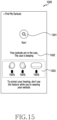
- the external electronic device 300 may display the information indicating that the audio output device 100 is in the power supply device, and the user may identify the information and may find the position of the audio output device 100 and/or the power supply device 200 which outputs the alarm.
- the control circuit 450 may transmit the information indicating that the audio output device 100 is in the power supply device and state information (for example, a battery charging rate) of the audio output device 100 to the external electronic device 300.
- the external electronic device 300 may output information regarding the position of the audio output device 100 to the user by using augmented reality (AR).
- AR augmented reality
- the external electronic device 300 may be AR glasses (or VR glasses).
- the external electronic device 300 may display information regarding the state of the audio output device 100 received in the power supply device 200 by using AR technology.
- the external electronic device 300 may display guide information regarding a direction and/or a distance of the position of the audio output device 100 received in the power supply device 200.
- the power supply device 200 may perform an additional function (for example, a relay function) for finding the audio output device 100.
- the power supply device 200 may output information regarding a direction in which the audio output device 100 is positioned with reference to the external electronic device 300 (or the power supply device 200). In this case, the external electronic device 300 may output a notification in a different method from that when the audio output device 100 is received in the power supply device 200.
- the above-described function of finding the position of the audio output device 100 by using the power supply device 200 in FIG. 5 may be performed when a specific application (for example, an application for controlling an electronic device of a user account) is executed in the external electronic device 300.
- a specific application for example, an application for controlling an electronic device of a user account
- UWB ultra-wide band
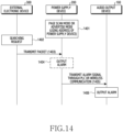
- the power supply device 200 may receive the signal for finding the audio output device 100 (and/or the power supply device 200) by using its own wireless communication address.
- the power supply device 200 may operate in the page scan mode or in the advertise mode by using the wireless communication address of the power supply device 200. A method for finding the audio output device 100 by using the wireless communication address of the power supply device 200 will be described in detail with reference to FIG. 14 .
- FIG. 6 illustrates a flowchart to explain a method for finding a position of the audio output device 100 through the power supply device 200 by using wireless communication (for example, Bluetooth legacy) according to an embodiment.
- wireless communication for example, Bluetooth legacy
- Actions of FIG. 6 may be performed by the power supply device 200 of FIG. 4 .
- the control circuit 450 of the power supply device 200 may perform: action 610 of, in a state where the power supply device 200 connects a first communication with the audio output device 100 or is electrically connected with the audio output device 100, operating in a connection standby mode by using a wireless communication address of the audio output device 100; action 620 of receiving a wireless communication connection request from the external electronic device 300, based on the wireless communication address of the audio output device 100; action 630 of connecting second communication with the external electronic device 300 in response to the wireless communication connection request being received; action 640 of receiving a packet including a signal for finding the audio output device 100 from the external electronic device 300 through the second communication; and action 650 of transmitting a signal for letting the audio output device 100 output an alarm to the audio output device 100 through the first communication or transmitting the signal to the audio output device 100 through the electrical connection.
- Action 610 of FIG. 6 may correspond to action 510 of FIG. 5
- action 640 of FIG. 6 may correspond to action 520 of FIG. 5
- action 650 of FIG. 6 may correspond to action 530 of FIG. 5 . Descriptions of portions corresponding to those described in FIG. 5 or repeated descriptions will be omitted, and the respective actions of FIG. 6 will be described.
- the control circuit 450 of the power supply device 200 may operate in the connection standby mode by using the wireless communication address (for example, a Bluetooth address) of the audio output device 100 in the state where the power supply device 200 connects wireless communication with the audio output device 100 or is electrically connected with the audio output device 100, and in action 620, may receive, from the external electronic device 300, a wireless communication (for example, Bluetooth or Bluetooth legacy) connection request based on the wireless communication address of the audio output device 100.
- a wireless communication for example, Bluetooth or Bluetooth legacy
- the control circuit 450 may perform a page scan action in the connection standby mode of action 610.
- a page scan mode may be a state in which a paging request is received from another peripheral electronic device including the external electronic device 300 to establish Bluetooth (or Bluetooth legacy) communication connection.
- the control circuit 450 may receive a Bluetooth communication connection request (that is, a paging request) based on the wireless communication address of the audio output device 100 from the external electronic device 300 in action 620.
- the control circuit 450 may recognize the Bluetooth communication connection request received from the external electronic device 300 as a signal for finding the audio output device 100.
- the control circuit 450 may always (or continuously) operate in the page scan mode by using the wireless communication circuit 410, or may periodically operate in the page scan mode by using the wireless communication circuit 410.
- the control circuit 450 of the power supply device 200 may connect wireless communication (for example, Bluetooth or Bluetooth legacy) with the external electronic device 300 in action 630.
- the control circuit 450 may receive a paging request using the wireless communication address of the audio output device 100 from the external electronic device 300, and may connect wireless communication with the external electronic device 300 by responding to the paging.
- control circuit 450 may perform page scanning by using the Bluetooth address of the audio output device 100, and in this case, the control circuit 450 may receive only the paging request using the Bluetooth address of the audio output device 100 from a peripheral electronic device (for example, the external electronic device 300), and may connect Bluetooth communication.
- a peripheral electronic device for example, the external electronic device 300
- the control circuit 450 of the power supply device 200 may receive the packet including the signal for finding the audio output device 100 from the external electronic device 300 through the wireless communication (that is, Bluetooth or Bluetooth legacy communication) connected with the external electronic device 300.
- the power supply device 200 and the external electronic device 300 may exchange data with each other by exchanging a communication packet including the data.
- the external electronic device 300 may transmit the packet including the signal for finding the audio output device 100 to the power supply device 200, and the power supply device 200 may receive the packet.
- the packet including the signal for finding the audio output device 100 may be configured as shown in table 1 presented below: Table 1 Cla ssifi cati on SOM (1byte) Header LSB (1byte) Header MSB (1byte) Msg ID (2 byte) Left Earbud Mute (1byte) right Earbud Mute (1byte) EOM (1 byte) Con tent s 0xFD 0x0A 0x00 0xA0 0x00 0X01 0xDD
- the signal for finding the audio output device 100 may include a signal for requesting a command for the audio output device 100 to output an alarm to be transmitted to the audio output device 100.
- the control circuit 450 of the power supply device 200 may transmit a signal for letting the audio output device 100 output an alarm to the audio output device 100 through wireless communication (that is, Bluetooth communication with the audio output device 100), or may transmit the signal to the audio output device 100 through electrical connection.
- Action 650 may correspond to description of action 530 of FIG. 5 , and thus a detailed description thereof is omitted.
- action 630 and action 640 may be omitted.
- the control circuit 450 when the control circuit 450 operating in the connection standby mode receives a wireless communication connection request from the external electronic device 300 in action 620, the control circuit 450 may recognize the wireless communication connection request as the signal for finding the audio output device 100, and may transmit the signal for letting the audio output device 100 output the alarm to the audio output device 100 in action 650.
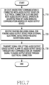
- FIG. 7 illustrates a flowchart to explain a method for finding a position of the audio output device 100 through the power supply device 200 by using an advertising signal according to an embodiment.
- Actions of FIG. 7 may be performed by the power supply device 200 of FIG. 4 .
- the control circuit 450 of the power supply device 200 may perform: action 710 of, in a state where a first communication is connected with the audio output device 100 or the power supply device 200 is electrically connected with the audio output device 100, operating in an advertise mode by using a wireless communication address of the audio output device 100; action 720 of receiving a packet including a signal for finding the audio output device 100 from the external electronic device 300 which receives an advertising signal; and action 730 of transmitting a signal for letting the audio output device 100 output an alarm to the audio output device 100 through the first communication, or transmitting the signal to the audio output device 100 through electrical connection.
- Action 710 of FIG. 7 may correspond to action 510 of FIG. 5
- action 720 of FIG. 7 may correspond to action 520 of FIG. 5
- action 730 of FIG. 7 may correspond to action 530 of FIG. 5 .
- descriptions of portions corresponding to those described in FIG. 5 or repeated descriptions will be omitted, and the respective actions of FIG. 7 will be described.
- the control circuit 450 of the power supply device 200 may operate in the advertise mode by using the wireless communication address (for example, a Bluetooth address) of the audio output device 100.
- the control circuit 450 may perform an action of transmitting an advertising signal to another peripheral electronic device including the external electronic device 300 in the advertise mode.
- the control circuit 450 may not exchange information with a specific electronic device with which communication is connected, but may transmit the advertising signal to all electronic devices existing on the periphery of the power supply device 200.
- the control circuit 450 may always (or continuously) transmit the advertising signal by using the wireless communication circuit 410, or may periodically transmit the advertising signal by using the wireless communication circuit 410.
- the control circuit 450 of the power supply device 200 may receive the packet including the signal for finding the audio output device 100 from the external electronic device 300, which receives the advertising signal.
- the external electronic device 300 may receive the signal while the power supply device 200 is transmitting the advertising signal, and may transmit a response packet to the power supply device 200 in response to the received advertising signal.
- the external electronic device 300 may include data in the response packet, and may transmit the response packet.
- the external electronic device 300 may include the signal for finding the audio output device 100 in the response packet, and may transmit the response packet to the power supply device 200.
- the signal for finding the audio output device 100 may include a signal for requesting a command for the audio output device 100 to output an alarm to be transmitted to the audio output device 100.
- the control circuit 450 of the power supply device 200 may transmit the signal for letting the audio output device 100 output the alarm to the audio output device 100 through wireless communication (for example, Bluetooth communication with the audio output device 100), or may transmit the signal to the audio output device 100 through electrical connection.
- Action 730 may correspond to description of action 530 of FIG. 5 , and thus a detailed description thereof is omitted.
- the power supply device 200 may operate in the page scan mode or in the advertise mode by using a first Bluetooth address of the first audio output device 100a and/or a second Bluetooth address of the second audio output device 100b.
- the power supply device 200 may operate in the page scan mode or in the advertise mode by using only the first Bluetooth address of a master device.
- the power supply device 200 may operate in the page scan mode or in the advertise mode by alternately using the first Bluetooth address and the second Bluetooth address with reference to a predetermined period.
- the external electronic device 300 may receive a request for finding the audio output device 100 from the user. However, this should not be considered as limiting, and the external electronic device 300 may receive, from the user, a request for finding the power supply device 200 or a request for finding the audio output device 100 and the power supply device 200.
- the power supply device 200 when the power supply device 200 receives the request for finding the power supply device 200 from the external electronic device 300 in the middle of operating in the connection standby mode or in the advertise mode by using the wireless communication address of the audio output device 100, the action of transmitting the signal for letting the audio output device 100 output the alarm to the audio output device 100 may be omitted. That is, when the power supply device 200 receives the request for finding the power supply device 200 from the external electronic device 300, the power supply device 200 may directly output an alarm (for example, a sound effect, a sound guide and/or a vibration).
- an alarm for example, a sound effect, a sound guide and/or a vibration
- the power supply device 200 when the power supply device 200 receives the request for finding the audio output device 100 and the power supply device 200 from the external electronic device 300 in the middle of operating in the connection standby mode or in the advertise mode by using the wireless communication address of the audio output device 100, the power supply device may transmit the signal for letting the audio output device 100 output the alarm to the audio output device 100, while directly outputting the alarm (for example, a sound effect, a sound guide sound, and/or a vibration).
- the alarm for example, a sound effect, a sound guide sound, and/or a vibration
- FIG. 8 illustrates a flowchart to explain a method for the audio output device 100 to output an alarm based on a signal received from the power supply device 200 according to an embodiment.
- Actions of FIG. 8 may be performed by the audio output device 100 of FIG. 3 .
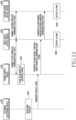
- the control circuit 380 of the audio output device 100 may perform: action 810 of disconnecting wireless communication from the external electronic device 300, and establishing a first communication connection with the power supply device 200 or electrical connection with the power supply device 200; action 820 of transmitting information regarding a wireless communication address to the power supply device 200 through the electrical connection; action 830 of receiving a signal for finding at least one audio output device 100, received by the power supply device 200 from the external electronic device 300, from the power supply device 200 through the first communication connection or the electrical connection with the power supply device 200; action 840 of outputting an alarm in response to the signal for finding the at least one audio output device 100 being received; and action 850 of transmitting a signal for letting another audio output device 100 output an alarm to another audio output device 100 in response to the signal for finding the at least one audio output device 100 being received.
- the respective actions may be performed in sequence, but may not necessarily be performed in sequence.
- the order of the respective actions may be changed and at least two actions may be performed in parallel.
- action 820 and/or action 850 may be omitted, and action 840 and action 850 may be performed substantially at the same time.
- FIG. 8 will be described in detail.
- the control circuit 380 of the audio output device 100 may disconnect wireless communication from the external electronic device 300, and may establish wireless communication connection with the power supply device 200 or electrical connection with the power supply device 200, and in action 820, the control circuit 380 of the audio output device 100 may transmit information regarding a wireless communication address of the audio output device 100 to the power supply device 200 through the electrical connection.
- the control circuit 380 of the audio output device 100 may disable the audio output device 100 or may disable at least one function of the audio output device 100, and may disconnect wireless communication (for example, Bluetooth communication) from the external electronic device 300.
- the control circuit 380 of the audio output device 100 may connect PLC with the power supply device 200 through electrical connection.
- the control circuit 380 may transmit information regarding the wireless communication address (for example, a Bluetooth address) of the audio output device 100 to the power supply device 200 through PLC.
- action 820 may be omitted.
- the control circuit 380 of the audio output device 100 may connect wireless communication (for example, Bluetooth communication) with the power supply device 200.
- the control circuit 380 may connect wireless communication with the power supply device 200 by using at least one method of relay, sniffing, TWS+ methods among Bluetooth communication methods.
- the power supply device 200 may already know information regarding the wireless communication address (for example, a Bluetooth address) of the audio output device 100, and action 820 may be omitted.
- the control circuit 380 of the audio output device 100 may receive the signal for finding at least one audio output device 100, received by the power supply device 200 from the external electronic device 300, from the power supply device 200 through the first communication connection or the electrical connection with the power supply device 200.
- the audio output device 100 may receive the signal for finding the audio output device 100 through the power supply device 200.
- the audio output device 100 may receive the signal for finding the audio output device 100 or a packet including the signal through the first communication (for example, Bluetooth communication) or PLC connected with the power supply device 200.
- the signal for finding the audio output device 100 may be a signal that is received by the power supply device 200 from the external electronic device 300 through communication established with the external electronic device 300 by using the Bluetooth address of the audio output device 100.
- the signal for finding the audio output device 100 may include a signal for letting the audio output device 100 output an alarm.
- the control circuit 380 of the audio output device 100 may output an alarm in response to the signal for finding at least one audio output device 100 being received.
- the control circuit 380 may control the audio processing circuit 340 to output a predetermined sound effect or sound guide and to inform the user of its own position.
- the control circuit 380 of the audio output device 100 may enable the audio output device 100 or may enable at least one disabled circuit (for example, the audio processing circuit 340) to output the predetermined sound effect or sound guide, in response to the signal for finding at least one audio output device 100 being received.
- the control circuit 380 of the audio output device 100 may transmit a signal for letting another audio output device 100 to output an alarm to another audio output device 100 (for example, the second audio output device 100b) in response to the signal for finding at least one audio output device 100 being received.
- wireless communication may be connected between the first audio output device 100a and the second audio output device 100b which forms a pair.
- the first audio output device 100a may transmit a signal for letting the second audio output device 100b to output an alarm in response to the signal for finding at least one audio output device 100 being received.
- the first audio output device 100a may be a master device and the second audio output device 100b may be a slave device. According to an embodiment, the first audio output device 100a may transmit the signal for letting the second audio output device 100b to output an alarm by using PLC with the power supply device 200.
- the power supply device 200 may perform PLC with the first audio output device 100a and the second audio output device 100b, and the first audio output device 100a may transmit the signal to the second audio output device 100b through the power supply device 200.
- action 850 may be omitted.
- not only Bluetooth communication but also UWB may be supported between the external electronic device 300 and the power supply device 200.
- the power supply device 200 may provide information regarding a distance and/or a direction of the audio output device 100 to the external electronic device 300 by using UWB communication.
- FIGS. 9 and 10 illustrate flowcharts to explain a method for finding the audio output device 100, based on a request of the external electronic device 300 according to an embodiment.
- FIG. 9 is a flowchart of an embodiment in which PLC is connected between the power supply device 200 and the audio output device 100 in a state where the audio output device 100 is received in the power supply device 200
- FIG. 10 is a flowchart of an embodiment in which wireless communication is connected between the power supply device 200 and the audio output device 100 in a state where the power supply device 200 and the audio output device 100 are spaced apart from each other.
- FIG. 5 will be described again with reference to FIGS. 9 and 10 .
- the power supply device 200 may be in a state in which PLC is connected with the audio output device 100.
- a terminal for example, the first interface 206, the second interface 208 of FIG. 1
- a terminal for example, the first interface 102, the second interface 104 of FIG. 1
- the power supply device 200 may perform PLC with the audio output device 100.
- the power supply device 200 may receive information regarding a Bluetooth address of the audio output device 100 through PLC with the audio output device 100.
- the power supply device 200 according to an embodiment may operate in a page scan mode or in an advertise mode by using the Bluetooth address of the audio output device 100. Actions 901 to 903 may correspond to description of action 510 of FIG. 5
- the external electronic device 300 may receive a searching request for the audio output device 100 (for example, a user input for finding the audio output device 100) in action 904.
- the external electronic device 300 may transmit a communication packet including a signal for finding the audio output device 100 to the power supply device 200 in action 905.
- the external electronic device 300 may connect Bluetooth communication with the power supply device 200 which operates in the scan mode, by using the Bluetooth address of the audio output device 100, and may transmit the packet including the signal for finding the audio output device 100 to the power supply device 200.
- the external electronic device 300 may transmit the packet including the signal for finding the audio output device 100 to the power supply device 200, which operates in the advertise mode by using the Bluetooth address of the audio output device 100, as a response signal.
- Actions 904 to 905 may correspond to description of action 520 of FIG. 5 .
- the power supply device 200 may receive the communication packet including the signal for finding the audio output device 100 from the external electronic device 300.
- the power supply device 200 may transmit a signal for letting the audio output device 100 output an alarm to the audio output device 100 through PLC with the audio output device 100.
- the audio output device 100 may reproduce audio data related to a sound effect or a sound guide in action 907.
- a user may find the position of the audio output device 100 by searching a position of the outputted sound effect or sound guide.
- Actions 906 to 907 may correspond to description of operation 520 of FIG. 5 .
- the power supply device 200 may be in a state where wireless communication is connected with the audio output device 100.
- the power supply device 200 may connect wireless communication with the audio output device 100 by using at least one of relay, sniffing and TWS+ methods among the Bluetooth communication methods.
- the power supply device 200 may operate in a page scan mode or an advertise method in action 1002 by using a Bluetooth address of the audio output device 100 which is used for Bluetooth communication connection with the audio output device 100.
- Actions 1001 to 1002 may correspond to description of action 510 of FIG. 5 .
- Actions 1003 to 1004 may correspond to actions 904 to 905 of FIG. 9 , and thus a redundant explanation thereof is omitted.
- the power supply device 200 may receive a communication packet including a signal for finding the audio output device 100 from the external electronic device 300, and in action 1005, the power supply device 200 may transmit a signal for letting the audio output device 100 output an alarm to the audio output device 100 through wireless communication (for example, Bluetooth communication).
- wireless communication for example, Bluetooth communication
- Action 1006 may correspond to action 907 of FIG. 9 and thus a redundant explanation thereof is omitted.
- FIG. 11 illustrates a view to explain various Bluetooth communication connection methods between the audio output device 100a 100b and the power supply device 200 according to an embodiment.
- FIG. 11 illustrates various methods of connecting Bluetooth communication between the plurality of audio output devices 100a, 100b and the power supply device 200.
- the communication connection method between the audio output device 100a, 100b and the power supply device 200 is not limited thereto, and for example, the above-described PLC connection may be usable.
- FIG. 11A illustrates an embodiment in which Bluetooth communication of a relay method is connected between the audio output device 100a, 100b and the power supply device 200.
- the power supply device 200 may connect communication (a) with the first audio output device 100a, which is a master device, and the first audio output device 100a which is the master device may connect communication (b) with the second audio output device 100b which is a slave device.
- FIG. 11B illustrates an embodiment in which Bluetooth communication of a sniffing method is connected between the audio output device 100a, 100b and the power supply device 200.
- the power supply device 200 may connect communication (a) with the first audio output device 100a, which is a master device, and the first audio output device 100a which is the master device may connect communication (b') with the second audio output device 100b which is a slave device.
- the second audio output device 100 may sniff data which is transmitted and received between the power supply device 200 and the first audio output device 100a, based on information regarding the communication path (a) between the power supply device 200 and the first audio output device 100a.
- FIG. 11C illustrates an embodiment in which Bluetooth communication of a TWS+ method is connected between the audio output device 100a, 100b and the power supply device 200.
- the power supply device 200 may connect communication (a) with the first audio output device 100a, and the first audio output device 100a may separately connect communication (c) with the second audio output device 100b.
- the first audio output device 100a and the second audio output device 100b may transmit and receive information by connecting communication with the power supply device 200, respectively.
- FIG. 12 illustrates a flowchart to explain a method for finding at least one audio output device 100a, 100b in the communication connection state of FIG. 11A or 11B , based on a request of the external electronic device 300 according to an embodiment.
- the power supply device 200 may be in a state in which first wireless communication is connected with the first audio output device 100a, and in action 1202, the first audio output device 100a may be in a state in which second wireless communication is connected with the second audio output device 100b.
- the first audio output device 100a and the second audio output device 100b may connect wireless communication with the power supply device 200 by using at least one of the relay method and the sniffing method among the Bluetooth communication methods.
- the power supply device 200 may know a first Bluetooth address of the first audio output device 100a in the process of establishing the first communication connection with the first audio output device 100a.
- the power supply device 200 may receive information regarding a second Bluetooth address of the second audio output device 100b through the first communication connection.
- the power supply device 200 may operate in a page scan mode or operate in an advertise mode by using the first Bluetooth address and/or the second Bluetooth address.
- the power supply device 200 may operate in the page scan mode or in the advertise mode by using only the first Bluetooth address of the master device.
- the power supply device 200 may operate in the page scan mode or in the advertise mode by alternately using the first Bluetooth address and the second Bluetooth address with reference to a predetermined period.
- the external electronic device 300 may receive a searching request for the audio output device 100a, 100b (for example, a user input for finding the audio output device 100) in action 1204.
- the external electronic device 300 may distinguish between a user input for finding the first audio output device 100a and a user input for finding the second audio output device 100b, and may receive the user input.
- the external electronic device 300 may receive a user input for finding both the first audio output device 100a and the second audio output device 100b.
- the external electronic device 300 may transmit a communication packet including a signal for finding at least one of the first audio output device 100a and the second audio output device 100b to the power supply device 200.
- the external electronic device 300 may connect Bluetooth communication with the power supply device 200, which operates in the scan mode by using the first Bluetooth address and/or the second Bluetooth address, and may transmit the packet including the signal for finding at least one of the first audio output device 100a and the second audio output device 100b to the power supply device 200.
- the external electronic device 300 may transmit the packet including the signal for finding at least one of the first audio output device 100a and the second audio output device 100b to the power supply device 200, which operates in the advertise mode, as a response signal.
- the power supply device 200 may receive the communication packet including the signal for finding at least one of the first audio output device 100a and the second audio output device 100b from the external electronic device 300, and in action 1206, the power supply device 200 may transmit, to the first audio output device 100a, a signal for letting at least one of the first audio output device 100a and the second audio output device 100b output an alarm, through the first wireless communication with the first audio output device 100a.
- the first audio output device 100a when the first audio output device 100a receives a signal for letting the first audio output device 100a output the alarm from the power supply device 200, the first audio output device 100a may reproduce audio data related to a sound effect or a sound guide in action 1208.
- the sound effect or sound guide reproduced by the first audio output device 100a may vary according to the presence/absence of the second audio output device 100b, the presence/absence of actions 1207 and 1209.
- a type and/or a volume of the sound effect or sound guide reproduced by the first audio output device 100a may vary according to the presence/absence of the second audio output device 100b.
- the first audio output device 100a when the first audio output device 100a receives a signal for letting the second audio output device 100b to output an alarm from the power supply device 200, the first audio output device 100a may transmit the signal for letting the second audio output device 100b output the alarm to the second audio output device 100b through a second wireless communication in action 1207.
- the second audio output device 100b when the second audio output device 100b receives the signal for letting the second audio output device 100b output the alarm from the first audio output device 100a, the second audio output device 100b may reproduce audio data related to a sound effect or a sound guide.
- the first audio output device 100a when the first audio output device 100a receives a signal for letting the first audio output device 100a and the second audio output device 100b output an alarm from the power supply device 200, the first audio output device 100a may reproduce audio data related to a sound effect or a sound guide in action 1208, and may transmit a signal for letting the second audio output device 100b output an alarm to the second audio output device 100b in action 1207.
- the second audio output device 100b may also reproduce audio data related to a sound effect or a sound guide in action 1209.
- FIG. 13 illustrates a flowchart to explain a method for finding at least one audio output device 100 in the communication connection state of FIG. 11C , based on a request of the external electronic device 300 according to an embodiment.
- the power supply device 200 may be in a state in which a first wireless communication is connected with the first audio output device 100a, and in action 1302, the power supply device 200 may be in a state in which a second wireless communication is connected with the second audio output device 100b.
- the power supply device 200 may connect wireless communication with the first audio output device 100a and the second audio output device 100b by using the TWS+ method among the Bluetooth communication methods.
- the power supply device 200 may know a first Bluetooth address of the first audio output device 100a in the process of establishing the first communication connection with the first audio output device 100a.
- the power supply device 200 according to an embodiment may know a second Bluetooth address of the second audio output device 100b in the process of establishing the second communication connection with the second audio output device 100b.
- the power supply device 200 may operate in a page scan mode or operate in an advertise mode by using the first Bluetooth address and/or the second Bluetooth address.
- the power supply device 200 may operate in the page scan mode or in the advertise mode by alternately using the first Bluetooth address and the second Bluetooth address with reference to a predetermined period.
- the external electronic device 300 may receive a searching request for the audio output device 100a, 100b (for example, a user input for finding the audio output device 100) in action 1304.
- the external electronic device 300 may distinguish between a user input for finding the first audio output device 100a and a user input for finding the second audio output device 100b, and may receive the user input.
- the external electronic device 300 may receive a user input for finding both the first audio output device 100a and the second audio output device 100b.
- the external electronic device 300 may transmit a communication packet including a signal for finding at least one of the first audio output device 100a and the second audio output device 100b to the power supply device 200.
- the external electronic device 300 may connect Bluetooth communication with the power supply device 200, which operates in the scan mode by using the first Bluetooth address and/or the second Bluetooth address, and may transmit the packet including the signal for finding at least one of the first audio output device 100a and the second audio output device 100b to the power supply device 200.
- the external electronic device 300 may transmit the packet including the signal for finding at least one of the first audio output device 100a and the second audio output device 100b to the power supply device 200, which operates in the advertise mode, as a response signal.
- the power supply device 200 when the power supply device 200 receives the communication packet including the signal for finding the first audio output device 100a from the external electronic device 300 in action 1305, the power supply device 200 may transmit, to the first audio output device 100a, a signal for letting the first audio output device 100a output an alarm, through the first wireless communication with the first audio output device 100a in action 1306.
- the first audio output device 100a when the first audio output device 100a receives the signal for letting the first audio output device 100a output the alarm from the power supply device 200, the first audio output device 100a may reproduce audio data related to a sound effect or a sound guide in action 1307.
- the power supply device 200 when the power supply device 200 receives the communication packet including the signal for finding the second audio output device 100b from the external electronic device 300 in action 1305, the power supply device 200 may transmit, to the second audio output device 100b, a signal for letting the second audio output device 100b output an alarm, through the second wireless communication with the second audio output device 100b in action 1308.
- the second audio output device 100b when the second audio output device 100b receives the signal for letting the second audio output device 100b output the alarm from the power supply device 200, the second audio output device 100a may reproduce audio data related to a sound effect or a sound guide in action 1309.
- the power supply device 200 when the power supply device 200 receives the communication packet including the signal for finding both the first audio output device 100a and the second audio output device 100b from the external electronic device 300 in action 1305, the power supply device 200 may transmit a signal for letting the first audio output device 100a output an alarm to the first audio output device 100a through the first wireless communication in action 1306, and may transmit a signal for letting the second audio output device 100b output an alarm to the second audio output device 100b through the second wireless communication in action 1308.
- the first audio output device 100a and the second audio output device 100b may reproduce audio data related to the sound effect or the sound guide all together (or substantially at the same time) in actions 1307 and 1309.
- FIG. 14 a flowchart to explain a method for finding the power supply device 200 and/or the audio output device 100 by using a wireless communication address of the power supply device 200, based on a request of the external electronic device 300 according to an embodiment.
- the power supply device 200 may operate in a page scan mode or in an advertise mode by using a Bluetooth address of the power supply device 200.
- the external electronic device 300 may receive a searching request for the power supply device 200 and/or the audio output device 100 (that is, a user input for finding the power supply device 200 and/or the audio output device 100) in action 1402.
- the external electronic device 300 may transmit a communication packet including a signal for finding the power supply device 200 and/or the audio output device 100 to the power supply device 200 in action 1403.
- the external electronic device 300 may connect Bluetooth communication with the power supply device 200 operating in the scan mode, and may transmit the packet including the signal for finding the power supply device 200 and/or the audio output device 100 to the power supply device 200. In another example, the external electronic device 300 may transmit the packet including the signal for finding the power supply device 200 and/or the audio output device 100 to the power supply device 200 operating in the advertise mode as a response signal.
- the external electronic device 300 may know a wireless communication address of the power supply device 200. Accordingly, the external electronic device 300 may connect wireless communication with the power supply device 200 based on the wireless communication address of the power supply device 200, and may transmit the communication packet including the signal for finding the power supply device 200 and/or the audio output device 100 to the power supply device 200, or may transmit the communication packet including the signal for finding the power supply device 200 and/or the audio output device to the power supply device 200 in response to an advertising signal being received based on the wireless communication address of the power supply device 200.
- the external electronic device 300 may contain, in the communication packet, not only the signal for finding the power supply device 200 and/or the audio output device 100 but also a signal for requesting a command for the audio output device 100 to output an alarm to be transmitted to the audio output device 100, and may transmit the communication packet to the power supply device 200.
- the external electronic device 300 since the power supply device 200 is connected with the external electronic device 300 by using its own wireless communication address, the external electronic device 300 may know information indicating that the audio output device 100 is received in the power supply device 200 in action 1403.
- the power supply device 200 may receive the communication packet including the signal for finding the power supply device 200 and/or the audio output device 100 from the external electronic device 300. For example, when the power supply device 200 receives the signal for finding the power supply device 200 from the external electronic device 300, the power supply device 200 may control an audio processing circuit to output an alarm in action 1404 if the power supply device 200 includes the audio processing circuit.
- the power supply device 200 may transmit a signal for letting the audio output device 100 output an alarm to the audio output device 100 through the communication with the audio output device 100 in operation 1405 if there is communication (for example, PLC communication, Bluetooth communication) connected between the power supply device 200 and the audio output device 100.
- communication for example, PLC communication, Bluetooth communication
- the audio output device 100 may reproduce audio data related to a sound effect or a sound guide in response to the alarm signal received from the power supply device 200.
- a user may find the position of the power supply device 200 and/or the audio output device 100 by searching a position of the sound effect or the sound guide outputted.
- FIG. 15 illustrates a view of an example of a user interface screen 1500 for finding the audio output device 100 in the external electronic device 300 according to an embodiment.
- the external electronic device 300 may find a position of the audio output device 100 by using the power supply device 200.
- the user interface screen 1500 of the external electronic device 300 for finding the audio output device 100 may include an icon 1501 for requesting searching of the audio output device 100, and may further include an area 1502 displaying information regarding a searching process (for example, searching, search completed, search error) of the audio output device 100, and an area 1503 displaying information regarding a state (for example, a battery state) of the power supply device 200 and the audio output device 100.
- a user may select the icon for finding the audio output device 100.
- the external electronic device 300 may transmit a signal for finding the audio output device 100 to the power supply device 200 by using a Bluetooth address of the audio output device 100 in response to an input on the icon.
- the signal for finding the audio output device 100 may include a signal for requesting a command for the audio output device 100 to output an alarm to be transmitted to the audio output device 100.
- the power supply device 200 may transmit information regarding the searching process of the audio output device 100 to the external electronic device 300 by using Bluetooth communication with the external electronic device 300.
- the information regarding the searching process of the audio output device 100 may include, for example, information indicating that a sound effect or a sound guide is outputted from the audio output device 100 and/or the power supply device 200, and information regarding whether the audio output device 100 is received in the power supply device 200.
- the power supply device 200 may also transmit information regarding the state of the audio output device 100 and the power supply device 200 (for example, a charging rate of the audio output device 100 and the power supply device 200) to the external electronic device 300.
- the external electronic device 300 which receives the information regarding the searching process of the audio output device 100 may output the information indicating that the sound effect or the sound guide is outputted from the audio output device 100 (and/or the power supply device 200) (1502).
- the external electronic device 300 which receives the information regarding the state of the audio output device 100 and the power supply device 200 may also output information regarding the charging rate of the audio output device 100 and the power supply device 200 (1503).
- the external electronic device 300 may output information indicating that the external electronic device 300 fails to communicate with the audio output device 100 and/or the power supply device 200.
- FIG. 16 illustrates a view of a method for finding the audio output device 100 by using a peripheral electronic device 300a and a server 400.
- the power supply device 200 may operate in an advertise mode by using a wireless communication address of the audio output device 100.
- the power supply device 200 may transmit an advertising signal to the peripheral electronic device 300a existing in the proximity of the power supply device 200.
- the power supply device 200 may not exchange information with a specific electronic device with which communication is connected, but may transmit advertising signals to all electronic devices existing in the proximity of the power supply device 200.
- the power supply device 200 may operate in the advertise mode when the power supply device 200 does not receive a signal from the external electronic device 300b which is communicatively connected with the audio output device 100, within a designated time, by using a wireless communication address of the audio output device 100.
- the peripheral electronic device 300a existing in the proximity of the power supply device 200 may receive the advertising signal transmitted by the power supply device 200.
- the peripheral electronic device 300a may not be the external electronic device 300b of a user account but an unspecific peripheral electronic device 300a existing in the proximity of the power supply device 200.
- the peripheral electronic device 300a which receives the advertising signal from the power supply device 200 may upload information regarding a corresponding position where the advertising signal is received on the server 400.
- the external electronic device 300b of the user account when the external electronic device 300b of the user account receives an input for finding the audio output device 100 from a user, the external electronic device 300b may use the information regarding the position where the peripheral electronic device 300a receives the advertising signal, which is uploaded on the server 400.
- the external electronic device 300b may output estimated position information of the power supply device 200 and the audio output device 100 by using the information uploaded on the server 400.
- the power supply device 200 may transmit a command to output an alarm (for example, a sound effect, a sound guide, and/or a vibration) to the audio output device 100 through PLC.
- the designated signal that the power supply device 200 receives from the external electronic device 300b may include a signal for requesting the command for the audio output device 100 to output the alarm to be transmitted to the audio output device 100.
- Fig. 17 illustrates a block diagram of an electronic device 1701 in a network environment 1700 according to various embodiments.
- the electronic device 1701 in the network environment 1700 may communicate with an electronic device 1702 via a first network 1798 (e.g., a short-range wireless communication network), or at least one of an electronic device 1704 or a server 1708 via a second network 1799 (e.g., a long-range wireless communication network).
- a first network 1798 e.g., a short-range wireless communication network
- a second network 1799 e.g., a long-range wireless communication network
- the electronic device 1701 may communicate with the electronic device 1704 via the server 1708.
- the electronic device 1701 may include a processor 1720, a memory 1730, an input module 1750, a sound output module 1755, a display module 1760, an audio module 1770, a sensor module 1776, an interface 1777, a connecting terminal 1778, a haptic module 1779, a camera module 1780, a power management module 1788, a battery 1789, a communication module 1790, a subscriber identification module(SIM) 1796, or an antenna module 1797.
- at least one of the components e.g., the connecting terminal 1778
- some of the components e.g., the sensor module 1776, the camera module 1780, or the antenna module 1797) may be implemented as a single component (e.g., the display module 1760).
- the processor 1720 may execute, for example, software (e.g., a program 1740) to control at least one other component (e.g., a hardware or software component) of the electronic device 1701 coupled with the processor 1720, and may perform various data processing or computation. According to one embodiment, as at least part of the data processing or computation, the processor 1720 may store a command or data received from another component (e.g., the sensor module 1776 or the communication module 1790) in the volatile memory 1732, process the command or the data stored in the volatile memory 1732, and store resulting data in the non-volatile memory 1734.
- software e.g., a program 1740
- the processor 1720 may store a command or data received from another component (e.g., the sensor module 1776 or the communication module 1790) in the volatile memory 1732, process the command or the data stored in the volatile memory 1732, and store resulting data in the non-volatile memory 1734.
- the processor 1720 may include a main processor 1721 (e.g., a central processing unit (CPU) or an application processor (AP)), or an auxiliary processor 1723 (e.g., a graphics processing unit (GPU), a neural processing unit (NPU), an image signal processor (ISP), a sensor hub processor, or a communication processor (CP)) that is operable independently from, or in conjunction with, the main processor 1721.
- a main processor 1721 e.g., a central processing unit (CPU) or an application processor (AP)
- auxiliary processor 1723 e.g., a graphics processing unit (GPU), a neural processing unit (NPU), an image signal processor (ISP), a sensor hub processor, or a communication processor (CP)
- the auxiliary processor 1723 may be adapted to consume less power than the main processor 1721, or to be specific to a specified function.
- the auxiliary processor 1723 may be implemented as separate from, or as part of the main processor 1721.
- the auxiliary processor 1723 may control at least some of functions or states related to at least one component (e.g., the display module 1760, the sensor module 1776, or the communication module 1790) among the components of the electronic device 1701, instead of the main processor 1721 while the main processor 1721 is in an inactive (e.g., sleep) state, or together with the main processor 1721 while the main processor 1721 is in an active state (e.g., executing an application).
- the auxiliary processor 1723 e.g., an image signal processor or a communication processor
- the auxiliary processor 1723 may include a hardware structure specified for artificial intelligence model processing.
- An artificial intelligence model may be generated by machine learning. Such learning may be performed, e.g., by the electronic device 1701 where the artificial intelligence is performed or via a separate server (e.g., the server 1708). Learning algorithms may include, but are not limited to, e.g., supervised learning, unsupervised learning, semi-supervised learning, or reinforcement learning.
- the artificial intelligence model may include a plurality of artificial neural network layers.
- the artificial neural network may be a deep neural network (DNN), a convolutional neural network (CNN), a recurrent neural network (RNN), a restricted boltzmann machine (RBM), a deep belief network (DBN), a bidirectional recurrent deep neural network (BRDNN), a deep Q-network or a combination of two or more thereof but is not limited thereto.
- the artificial intelligence model may, additionally or alternatively, include a software structure other than the hardware structure.
- the memory 1730 may store various data used by at least one component (e.g., the processor 1720 or the sensor module 1776) of the electronic device 1701.
- the various data may include, for example, software (e.g., the program 1740) and input data or output data for a command related thereto.
- the memory 1730 may include the volatile memory 1732 or the non-volatile memory 1734.
- the program 1740 may be stored in the memory 1730 as software, and may include, for example, an operating system (OS) 1742, middleware 1744, or an application 1746.
- OS operating system
- middleware middleware
- application application
- the input module 1750 may receive a command or data to be used by another component (e.g., the processor 1720) of the electronic device 1701, from the outside (e.g., a user) of the electronic device 1701.
- the input module 1750 may include, for example, a microphone, a mouse, a keyboard, a key (e.g., a button), or a digital pen (e.g., a stylus pen).
- the sound output module 1755 may output sound signals to the outside of the electronic device 1701.
- the sound output module 1755 may include, for example, a speaker or a receiver.
- the speaker may be used for general purposes, such as playing multimedia or playing record.
- the receiver may be used for receiving incoming calls. According to an embodiment, the receiver may be implemented as separate from, or as part of the speaker.
- the display module 1760 may visually provide information to the outside (e.g., a user) of the electronic device 1701.
- the display module 1760 may include, for example, a display, a hologram device, or a projector and control circuitry to control a corresponding one of the display, hologram device, and projector.
- the display module 1760 may include a touch sensor adapted to detect a touch, or a pressure sensor adapted to measure the intensity of force incurred by the touch.
- the audio module 1770 may convert a sound into an electrical signal and vice versa. According to an embodiment, the audio module 1770 may obtain the sound via the input module 1750, or output the sound via the sound output module 1755 or a headphone of an external electronic device (e.g., an electronic device 1702) directly (e.g., wired) or wirelessly coupled with the electronic device 1701.
- an external electronic device e.g., an electronic device 1702
- directly e.g., wired
- the sensor module 1776 may detect an operational state (e.g., power or temperature) of the electronic device 1701 or an environmental state (e.g., a state of a user) external to the electronic device 1701, and then generate an electrical signal or data value corresponding to the detected state.
- the sensor module 1776 may include, for example, a gesture sensor, a gyro sensor, an atmospheric pressure sensor, a magnetic sensor, an acceleration sensor, a grip sensor, a proximity sensor, a color sensor, an infrared (IR) sensor, a biometric sensor, a temperature sensor, a humidity sensor, or an illuminance sensor.
- the interface 1777 may support one or more specified protocols to be used for the electronic device 1701 to be coupled with the external electronic device (e.g., the electronic device 1702) directly (e.g., wired) or wirelessly.
- the interface 1777 may include, for example, a high definition multimedia interface (HDMI), a universal serial bus (USB) interface, a secure digital (SD) card interface, or an audio interface.
- HDMI high definition multimedia interface
- USB universal serial bus
- SD secure digital
- a connecting terminal 1778 may include a connector via which the electronic device 1701 may be physically connected with the external electronic device (e.g., the electronic device 1702).
- the connecting terminal 1778 may include, for example, a HDMI connector, a USB connector, a SD card connector, or an audio connector (e.g., a headphone connector).
- the haptic module 1779 may convert an electrical signal into a mechanical stimulus (e.g., a vibration or a movement) or electrical stimulus which may be recognized by a user via his tactile sensation or kinesthetic sensation.
- the haptic module 1779 may include, for example, a motor, a piezoelectric element, or an electric stimulator.
- the camera module 1780 may capture a still image or moving images.
- the camera module 1780 may include one or more lenses, image sensors, image signal processors, or flashes.
- the power management module 1788 may manage power supplied to the electronic device 1701. According to one embodiment, the power management module 1788 may be implemented as at least part of, for example, a power management integrated circuit (PMIC).
- PMIC power management integrated circuit
- the battery 1789 may supply power to at least one component of the electronic device 1701.
- the battery 1789 may include, for example, a primary cell which is not rechargeable, a secondary cell which is rechargeable, or a fuel cell.
- the communication module 1790 may support establishing a direct (e.g., wired) communication channel or a wireless communication channel between the electronic device 1701 and the external electronic device (e.g., the electronic device 1702, the electronic device 1704, or the server 1708) and performing communication via the established communication channel.
- the communication module 1790 may include one or more communication processors that are operable independently from the processor 1720 (e.g., the application processor (AP)) and supports a direct (e.g., wired) communication or a wireless communication.
- AP application processor
- the communication module 1790 may include a wireless communication module 1792 (e.g., a cellular communication module, a short-range wireless communication module, or a global navigation satellite system (GNSS) communication module) or a wired communication module 1794 (e.g., a local area network (LAN) communication module or a power line communication (PLC) module).
- a wireless communication module 1792 e.g., a cellular communication module, a short-range wireless communication module, or a global navigation satellite system (GNSS) communication module
- GNSS global navigation satellite system
- wired communication module 1794 e.g., a local area network (LAN) communication module or a power line communication (PLC) module.
- LAN local area network
- PLC power line communication
- a corresponding one of these communication modules may communicate with the external electronic device via the first network 1798 (e.g., a short-range communication network, such as Bluetooth TM , wireless-fidelity (Wi-Fi) direct, or infrared data association (IrDA)) or the second network 1799 (e.g., a long-range communication network, such as a legacy cellular network, a 5G network, a next-generation communication network, the Internet, or a computer network (e.g., LAN or wide area network (WAN)).
- first network 1798 e.g., a short-range communication network, such as Bluetooth TM , wireless-fidelity (Wi-Fi) direct, or infrared data association (IrDA)
- the second network 1799 e.g., a long-range communication network, such as a legacy cellular network, a 5G network, a next-generation communication network, the Internet, or a computer network (e.g., LAN or wide area network (WAN)).
- the wireless communication module 1792 may identify and authenticate the electronic device 1701 in a communication network, such as the first network 1798 or the second network 1799, using subscriber information (e.g., international mobile subscriber identity (IMSI)) stored in the subscriber identification module 1796.
- subscriber information e.g., international mobile subscriber identity (IMSI)
- the wireless communication module 1792 may support a 5G network, after a 4G network, and next-generation communication technology, e.g., new radio (NR) access technology.
- the NR access technology may support enhanced mobile broadband (eMBB), massive machine type communications (mMTC), or ultra-reliable and low-latency communications (URLLC).
- eMBB enhanced mobile broadband
- mMTC massive machine type communications
- URLLC ultra-reliable and low-latency communications
- the wireless communication module 1792 may support a high-frequency band (e.g., the mmWave band) to achieve, e.g., a high data transmission rate.
- the wireless communication module 1792 may support various technologies for securing performance on a high-frequency band, such as, e.g., beamforming, massive multiple-input and multiple-output (massive MIMO), full dimensional MIMO (FD-MIMO), array antenna, analog beam-forming, or large scale antenna.
- the wireless communication module 1792 may support various requirements specified in the electronic device 1701, an external electronic device (e.g., the electronic device 1704), or a network system (e.g., the second network 1799).
- the wireless communication module 1792 may support a peak data rate (e.g., 20Gbps or more) for implementing eMBB, loss coverage (e.g., 164dB or less) for implementing mMTC, or U-plane latency (e.g., 0.5ms or less for each of downlink (DL) and uplink (UL), or a round trip of 1ms or less) for implementing URLLC.
- a peak data rate e.g., 20Gbps or more
- loss coverage e.g., 164dB or less
- U-plane latency e.g., 0.5ms or less for each of downlink (DL) and uplink (UL), or a round trip of 1ms or less
- the antenna module 1797 may transmit or receive a signal or power to or from the outside (e.g., the external electronic device) of the electronic device 1701.
- the antenna module 1797 may include an antenna including a radiating element composed of a conductive material or a conductive pattern formed in or on a substrate (e.g., a printed circuit board (PCB)).
- the antenna module 1797 may include a plurality of antennas (e.g., array antennas). In such a case, at least one antenna appropriate for a communication scheme used in the communication network, such as the first network 1798 or the second network 1799, may be selected, for example, by the communication module 1790 (e.g., the wireless communication module 1792) from the plurality of antennas.
- the signal or the power may then be transmitted or received between the communication module 1790 and the external electronic device via the selected at least one antenna.
- another component e.g., a radio frequency integrated circuit (RFIC)
- RFIC radio frequency integrated circuit
- the antenna module 1797 may form a mm Wave antenna module.
- the mm Wave antenna module may include a printed circuit board, a RFIC disposed on a first surface (e.g., the bottom surface) of the printed circuit board, or adjacent to the first surface and capable of supporting a designated high-frequency band (e.g., the mmWave band), and a plurality of antennas (e.g., array antennas) disposed on a second surface (e.g., the top or a side surface) of the printed circuit board, or adjacent to the second surface and capable of transmitting or receiving signals of the designated high-frequency band.
- a RFIC disposed on a first surface (e.g., the bottom surface) of the printed circuit board, or adjacent to the first surface and capable of supporting a designated high-frequency band (e.g., the mmWave band)
- a plurality of antennas e.g., array antennas
- At least some of the above-described components may be coupled mutually and communicate signals (e.g., commands or data) therebetween via an inter-peripheral communication scheme (e.g., a bus, general purpose input and output (GPIO), serial peripheral interface (SPI), or mobile industry processor interface (MIPI)).
- an inter-peripheral communication scheme e.g., a bus, general purpose input and output (GPIO), serial peripheral interface (SPI), or mobile industry processor interface (MIPI)
- commands or data may be transmitted or received between the electronic device 1701 and the external electronic device 1704 via the server 1708 coupled with the second network 1799.
- Each of the electronic devices 1702 or 1704 may be a device of a same type as, or a different type, from the electronic device 1701.
- all or some of operations to be executed at the electronic device 1701 may be executed at one or more of the external electronic devices 1702, 1704, or 1708.
- the electronic device 1701 instead of, or in addition to, executing the function or the service, may request the one or more external electronic devices to perform at least part of the function or the service.
- the one or more external electronic devices receiving the request may perform the at least part of the function or the service requested, or an additional function or an additional service related to the request, and transfer an outcome of the performing to the electronic device 1701.
- the electronic device 1701 may provide the outcome, with or without further processing of the outcome, as at least part of a reply to the request.
- a cloud computing, distributed computing, mobile edge computing (MEC), or client-server computing technology may be used, for example.
- the electronic device 1701 may provide ultra low-latency services using, e.g., distributed computing or mobile edge computing.
- the external electronic device 1704 may include an internet-of-things (IoT) device.
- the server 1708 may be an intelligent server using machine learning and/or a neural network.
- the external electronic device 1704 or the server 1708 may be included in the second network 1799.
- the electronic device 1701 may be applied to intelligent services (e.g., smart home, smart city, smart car, or healthcare) based on 5G communication technology or IoT-related technology.
- the electronic device may be one of various types of electronic devices.
- the electronic devices may include, for example, a portable communication device (e.g., a smartphone), a computer device, a portable multimedia device, a portable medical device, a camera, a wearable device, or a home appliance. According to an embodiment of the disclosure, the electronic devices are not limited to those described above.
- each of such phrases as “A or B,” “at least one of A and B,” “at least one of A or B,” “A, B, or C,” “at least one of A, B, and C,” and “at least one of A, B, or C,” may include any one of, or all possible combinations of the items enumerated together in a corresponding one of the phrases.
- such terms as “1st” and “2nd,” or “first” and “second” may be used to simply distinguish a corresponding component from another, and does not limit the components in other aspect (e.g., importance or order).
- an element e.g., a first element
- the element may be coupled with the other element directly (e.g., wired), wirelessly, or via a third element.
- module may include a unit implemented in hardware, software, or firmware, and may interchangeably be used with other terms, for example, “logic,” “logic block,” “part,” or “circuitry”.
- a module may be a single integral component, or a minimum unit or part thereof, adapted to perform one or more functions.
- the module may be implemented in a form of an application-specific integrated circuit (ASIC).
- ASIC application-specific integrated circuit
- Various embodiments as set forth herein may be implemented as software (e.g., the program 1740) including one or more instructions that are stored in a storage medium (e.g., internal memory 1736 or external memory 1738) that is readable by a machine (e.g., the electronic device 1701).
- a processor e.g., the processor 1720 of the machine (e.g., the electronic device 1701) may invoke at least one of the one or more instructions stored in the storage medium, and execute it, with or without using one or more other components under the control of the processor. This allows the machine to be operated to perform at least one function according to the at least one instruction invoked.
- the one or more instructions may include a code generated by a complier or a code executable by an interpreter.
- the machine-readable storage medium may be provided in the form of a non-transitory storage medium.
- non-transitory simply means that the storage medium is a tangible device, and does not include a signal (e.g., an electromagnetic wave), but this term does not differentiate between where data is semi-permanently stored in the storage medium and where the data is temporarily stored in the storage medium.
- a method may be included and provided in a computer program product.
- the computer program product may be traded as a product between a seller and a buyer.
- the computer program product may be distributed in the form of a machine-readable storage medium (e.g., compact disc read only memory (CD-ROM)), or be distributed (e.g., downloaded or uploaded) online via an application store (e.g., PlayStore TM ), or between two user devices (e.g., smart phones) directly. If distributed online, at least part of the computer program product may be temporarily generated or at least temporarily stored in the machine-readable storage medium, such as memory of the manufacturer's server, a server of the application store, or a relay server.
- CD-ROM compact disc read only memory
- an application store e.g., PlayStore TM
- two user devices e.g., smart phones
- each component e.g., a module or a program of the above-described components may include a single entity or multiple entities, and some of the multiple entities may be separately disposed in different components. According to various embodiments, one or more of the above-described components may be omitted, or one or more other components may be added. Alternatively or additionally, a plurality of components (e.g., modules or programs) may be integrated into a single component. In such a case, according to various embodiments, the integrated component may still perform one or more functions of each of the plurality of components in the same or similar manner as they are performed by a corresponding one of the plurality of components before the integration.
- operations performed by the module, the program, or another component may be carried out sequentially, in parallel, repeatedly, or heuristically, or one or more of the operations may be executed in a different order or omitted, or one or more other operations may be added.
- an electronic device may include: a wireless communication circuit 410; a power management circuit 430; and a control circuit 450 electrically connected with the wireless communication circuit 410 and the power management circuit 430, and the control circuit 450 may be configured to: in a state where the electronic device connects a first communication with a first audio output device by using the wireless communication circuit 410, or is electrically connected with the first audio output device by using the power management circuit 430, operate in a connection standby mode or in an advertise mode by using a first wireless communication address of the first audio output device; receive a signal for finding the first audio output device from an external electronic device, based on the first wireless communication address; and, in response to the signal for finding the first audio output device being received, transmit a signal for letting the first audio output device output a notification (or an alarm) to the first audio output device through the first communication, or to transmit the signal to the first audio output
- control circuit 410 may perform a page scan action in the connection standby mode through the wireless communication circuit 410, and may perform an action of transmitting an advertising signal to a peripheral electronic device including the external electronic device in the advertise mode.
- the control circuit 450 when operating in the connection standby mode by using the first wireless communication address, may receive a wireless communication connection request based on the first wireless communication address from the external electronic device, may connect second communication with the external electronic device in response to the wireless communication connection request being received, and may receive a packet including the signal for finding the first audio output device from the external electronic device through the second communication.
- the control circuit 450 may transmit an advertising signal based on the first wireless communication address to a peripheral electronic device including the external electronic device, and may receive a packet including the signal for finding the first audio output device from the external electronic device which receives the advertising signal.
- control circuit 450 may PLC with the first audio output device when being electrically connected with the first audio output device.
- control circuit 450 may receive information regarding the first wireless communication address of the first audio output device through the PLC when being electrically connected with the first audio output device.
- control circuit 450 may further receive a signal for finding a second audio output device from the external electronic device, based on the first wireless communication address, and, in response to the signal for finding the second audio output device being received, may transmit a signal for letting the second audio output device output a notification to the first audio output device through the first communication.
- control circuit 450 may further transmit a signal for enabling the first audio output device to the first audio output device through the electrical connection when the first audio output device is disabled.
- a method for finding a position of an audio output device for example, the audio output device 100 of FIG. 1 , the audio output device 100 of FIG. 3 ) by using an electronic device (for example the power supply device 200 of FIG. 1 , the power supply device 200 of FIG.
- 4 may include: in a state where the electronic device connects a first communication with a first audio output device or is electrically connected with the first audio output device, operating in a connection standby mode or in an advertise mode by using a first wireless communication address of the first audio output device; receiving a signal for finding the first audio output device from an external electronic device, based on the first wireless communication address; and, in response to the signal for finding the first audio output device being received, transmitting a signal for letting the first audio output device output a notification (or an alarm) to the first audio output device through the first communication, or transmitting the signal to the first audio output device through the electrical connection.
- operating in the connection standby mode may include operating in a page scan mode
- operating in the advertise mode may include transmitting an advertising signal to a peripheral electronic device including the external electronic device.
- operating in the connection standby mode by using the first wireless communication address of the first audio output device may include: receiving a wireless communication connection request based on the first wireless communication address from the external electronic device; connecting a second communication with the external electronic device in response to the wireless communication connection request being received; and receiving a packet including the signal for finding the first audio output device from the external electronic device through the second communication.
- operating in the advertise mode by using the first wireless communication address of the first audio output device may include: transmitting an advertising signal based on the first wireless communication address to a peripheral electronic device including the external electronic device; and receiving a packet including the signal for finding the first audio output device from the external electronic device which receives the advertising signal.
- the electronic device may perform PLC with the first audio output device when being electrically connected with the first audio output device.
- the method may further include receiving information regarding the first wireless communication address of the first audio output device through the PLC when the electronic device is electrically connected with the first audio output device.
- the method may further include: receiving a signal for finding a second audio output device from the external electronic device, based on the first wireless communication address; and, in response to the signal for finding the second audio output device being received, transmitting a signal for letting the second audio output device output a notification to the first audio output device through the first communication.
- transmitting the signal for letting the first audio output device output the notification to the first audio output device through the electrical connection may include transmitting a signal for enabling the first audio output device to the first audio output device through the electrical connection when the first audio output device is disabled.
- an audio output device (for example, the audio output device 100 of FIG. 1 , the audio output device 100 of FIG. 3 ) may include: an audio processing circuit 340; a power management circuit 360: a wireless communication circuit 310 configured to establish communication connection by using a wireless communication address; and a control circuit 380 electrically connected with the audio processing circuit 340, the power management circuit 360, and the wireless communication circuit 310, and the control circuit 380 may establish a first communication connection with a power supply device by using the wireless communication circuit 310, or electrical connection with the power supply device by using the power management circuit 360, may receive, from the power supply device, a signal for finding at least one audio output device including the audio output device, the signal being received by the power supply device from an external electronic device, and in response to the signal for finding the at least one audio output device being received, may control the audio processing circuit 340 to output a notification (or an alarm).
- a notification or an alarm
- control circuit 380 may establish the first communication connection with the power supply device or the electrical connection with the power supply device, and, when the electrical connection with the power supply device is established, may transmit information regarding the wireless communication address to the power supply device through the electrical connection.
- control circuit 380 may transmit a signal for letting another audio output device output a notification to the another audio output device.
- the signal for finding the at least one audio output device may be a signal that is received from an external electronic device through communication with the external electronic device that is established by the power supply device by using a Bluetooth address of the audio output device.
Landscapes
- Engineering & Computer Science (AREA)
- Signal Processing (AREA)
- Physics & Mathematics (AREA)
- Acoustics & Sound (AREA)
- Health & Medical Sciences (AREA)
- General Health & Medical Sciences (AREA)
- Otolaryngology (AREA)
- Computer Networks & Wireless Communication (AREA)
- General Physics & Mathematics (AREA)
- Computer Security & Cryptography (AREA)
- Charge And Discharge Circuits For Batteries Or The Like (AREA)
- Circuit For Audible Band Transducer (AREA)
- Telephone Function (AREA)
- Mobile Radio Communication Systems (AREA)
Applications Claiming Priority (2)
| Application Number | Priority Date | Filing Date | Title |
|---|---|---|---|
| KR1020200186522A KR102822203B1 (ko) | 2020-12-29 | 2020-12-29 | 전력 공급 장치를 이용하여 오디오 출력 장치를 찾는 방법 및 그 전력 공급 장치 |
| PCT/KR2021/019912 WO2022145914A1 (ko) | 2020-12-29 | 2021-12-27 | 전력 공급 장치를 이용하여 오디오 출력 장치를 찾는 방법 및 그 전력 공급 장치 |
Publications (2)
| Publication Number | Publication Date |
|---|---|
| EP4199535A1 true EP4199535A1 (de) | 2023-06-21 |
| EP4199535A4 EP4199535A4 (de) | 2024-07-17 |
Family
ID=82259776
Family Applications (1)
| Application Number | Title | Priority Date | Filing Date |
|---|---|---|---|
| EP21915712.0A Pending EP4199535A4 (de) | 2020-12-29 | 2021-12-27 | Verfahren zum auffinden einer audioausgabevorrichtung unter verwendung einer stromversorgungsvorrichtung und stromversorgungsvorrichtung dafür |
Country Status (5)
| Country | Link |
|---|---|
| US (1) | US12207065B2 (de) |
| EP (1) | EP4199535A4 (de) |
| KR (1) | KR102822203B1 (de) |
| CN (1) | CN116671129A (de) |
| WO (1) | WO2022145914A1 (de) |
Families Citing this family (1)
| Publication number | Priority date | Publication date | Assignee | Title |
|---|---|---|---|---|
| CN115273431B (zh) * | 2022-09-26 | 2023-03-07 | 荣耀终端有限公司 | 设备的寻回方法、装置、存储介质和电子设备 |
Family Cites Families (37)
| Publication number | Priority date | Publication date | Assignee | Title |
|---|---|---|---|---|
| US8380125B2 (en) * | 2004-09-01 | 2013-02-19 | Kyocera Corporation | Systems and methods for bluetooth resource conservation |
| US8295532B2 (en) * | 2008-01-11 | 2012-10-23 | Broadcom Corporation | Method and system for wireless headset instant on capability during battery charging |
| EP2654769B1 (de) | 2010-12-14 | 2020-04-15 | Recepta Biopharma S.A. | Antitumorpeptid aus einem komplementaritätsbestimmenden bereich eines humanisierten monoklonalen antikörpers gegen den napi2b-transporter |
| JP6019544B2 (ja) | 2011-06-07 | 2016-11-02 | 富士通株式会社 | 無線通信システムおよび加入者情報管理装置 |
| KR101246990B1 (ko) | 2012-03-29 | 2013-03-25 | 신두식 | 이동통신단말기 분실 방지 기능을 갖는 헤드셋 및 분실 방지 기능을 갖는 헤드셋 시스템 |
| US20130298208A1 (en) * | 2012-05-06 | 2013-11-07 | Mourad Ben Ayed | System for mobile security |
| US10572700B2 (en) * | 2013-06-26 | 2020-02-25 | Vypin, LLC | Wireless asset location tracking system and related techniques |
| US9148717B2 (en) | 2014-02-21 | 2015-09-29 | Alpha Audiotronics, Inc. | Earbud charging case |
| EP3195619B1 (de) * | 2014-09-15 | 2018-03-21 | Sonova AG | Hörhilfesystem und methode unter verwendung von bluetooth-profilen |
| KR102325338B1 (ko) * | 2014-12-05 | 2021-11-11 | 삼성전자주식회사 | 전자 장치, 오디오 장치 및 전원 제어 방법 |
| KR102351368B1 (ko) | 2015-08-12 | 2022-01-14 | 삼성전자주식회사 | 전자 장치에서 오디오 출력 방법 및 장치 |
| CN105228043B (zh) * | 2015-09-29 | 2019-03-26 | 深圳罗马仕科技有限公司 | 车载蓝牙耳机装置及其控制方法 |
| US9967648B2 (en) * | 2015-09-30 | 2018-05-08 | Apple Inc. | Case with magnetic over-center mechanism |
| JP6761634B2 (ja) * | 2015-12-25 | 2020-09-30 | 任天堂株式会社 | 無線システム、無線機器、通信プログラム、および通信方法 |
| KR20170082405A (ko) * | 2016-01-06 | 2017-07-14 | 삼성전자주식회사 | 이어 웨어러블 타입 와이어리스 디바이스 및 이를 지원하는 시스템 |
| GB2549401A (en) * | 2016-04-13 | 2017-10-18 | Binatone Electronics Int Ltd | Audio systems |
| US10206474B2 (en) | 2016-09-06 | 2019-02-19 | Apple Inc. | Inductively chargeable earbud case |
| US9949015B1 (en) * | 2016-09-23 | 2018-04-17 | Apple Inc. | Wireless headset carrying case with wireless transmitter |
| KR101904281B1 (ko) | 2017-07-31 | 2018-10-04 | (주)그립 | 생체인식과 근거리 무선 통신을 이용한 피아식별 장치 및 모니터링 시스템 |
| KR102366797B1 (ko) | 2017-08-22 | 2022-02-23 | 삼성전자주식회사 | 자력을 이용한 개폐 구조를 갖는 커버를 포함하는 전자 장치 |
| KR102335903B1 (ko) * | 2017-09-29 | 2021-12-06 | 삼성전자주식회사 | 전자 장치들 간에 통신 방법 및 장치 |
| US11043086B1 (en) * | 2017-10-19 | 2021-06-22 | Pb Inc. | Voice-coded finder and radiotag tracker |
| CN108174457B (zh) | 2018-01-12 | 2020-09-01 | 恒玄科技(上海)股份有限公司 | 充电盒、蓝牙耳机的通信系统和通信方法 |
| US11290802B1 (en) * | 2018-01-30 | 2022-03-29 | Amazon Technologies, Inc. | Voice detection using hearable devices |
| US20190045292A1 (en) * | 2018-05-16 | 2019-02-07 | Intel Corporation | Extending battery life in headphones via acoustic idle detection |
| EP3621067A1 (de) * | 2018-05-18 | 2020-03-11 | Shenzhen Aukey Smart Information Technology Co., Ltd. | Sprachinteraktionsverfahren, -vorrichtung und -system |
| EP3621068A4 (de) * | 2018-05-18 | 2021-07-21 | Shenzhen Aukey Smart Information Technology Co., Ltd. | Tragbare intelligente sprachinteraktionssteuervorrichtung, verfahren und system |
| EP3627501B1 (de) * | 2018-05-18 | 2023-10-18 | Shenzhen Aukey Smart Information Technology Co., Ltd. | Kopfhörer, am handgelenk getragene sprachinteraktionsvorrichtung und system |
| CN108683998A (zh) * | 2018-06-12 | 2018-10-19 | 歌尔科技有限公司 | Tws耳机防丢方法、tws耳机、终端以及防丢系统 |
| CN109413556B (zh) | 2018-09-30 | 2021-03-02 | Oppo广东移动通信有限公司 | 设备定位方法、装置、耳机装置以及电子设备 |
| US10448211B1 (en) * | 2018-11-07 | 2019-10-15 | Adero, Inc. | Organizing groups of physical objects using wireless tags |
| CN109492441A (zh) | 2019-01-28 | 2019-03-19 | 上海与德通讯技术有限公司 | 一种蓝牙耳机的防丢方法、装置、电子设备及存储介质 |
| US10972825B2 (en) * | 2019-01-31 | 2021-04-06 | Bby Solutions, Inc. | Low power wireless charging using tuned NFC for headphone devices |
| KR102609837B1 (ko) | 2019-04-04 | 2023-12-05 | 삼성전자 주식회사 | 전원 라인을 통해 외부 장치와 통신할 수 있는 전자 장치 및 방법 |
| CN111225366A (zh) * | 2019-12-27 | 2020-06-02 | 宇龙计算机通信科技(深圳)有限公司 | 设备的查找方法、装置、存储介质及终端 |
| CN211352418U (zh) * | 2020-03-10 | 2020-08-25 | 深圳市功夫龙实业有限公司 | 一种防丢型无线耳机充电盒 |
| US11877212B2 (en) * | 2020-12-30 | 2024-01-16 | Arris Enterprises Llc | System and method for device location |
-
2020
- 2020-12-29 KR KR1020200186522A patent/KR102822203B1/ko active Active
-
2021
- 2021-12-27 EP EP21915712.0A patent/EP4199535A4/de active Pending
- 2021-12-27 WO PCT/KR2021/019912 patent/WO2022145914A1/ko not_active Ceased
- 2021-12-27 CN CN202180088526.8A patent/CN116671129A/zh active Pending
-
2022
- 2022-10-11 US US18/045,767 patent/US12207065B2/en active Active
Also Published As
| Publication number | Publication date |
|---|---|
| KR102822203B1 (ko) | 2025-06-18 |
| US20230066296A1 (en) | 2023-03-02 |
| CN116671129A (zh) | 2023-08-29 |
| US12207065B2 (en) | 2025-01-21 |
| WO2022145914A1 (ko) | 2022-07-07 |
| EP4199535A4 (de) | 2024-07-17 |
| KR20220094863A (ko) | 2022-07-06 |
Similar Documents
| Publication | Publication Date | Title |
|---|---|---|
| US12292773B2 (en) | Electronic device comprising connector | |
| US12353871B2 (en) | Electronic device, and method for updating external electronic device using same | |
| US12323758B2 (en) | Electronic device for audio, and method for managing power in electronic device for audio | |
| KR102864056B1 (ko) | 오디오 출력 장치의 충전 상태에 대한 정보를 전송하는 방법 및 그 오디오 출력 장치 | |
| US20220086578A1 (en) | Electronic device for outputting sound and method for operating the same | |
| US12363519B2 (en) | Apparatus and method for establishing a connection | |
| US20260056593A1 (en) | Method for controlling electronic devices and electronic device thereof | |
| US12045540B2 (en) | Audio device for processing audio data and operation method thereof | |
| US11973356B2 (en) | Method and electronic device for providing fast charging | |
| US12207065B2 (en) | Power supply device and method for searching audio output device using power supply device | |
| KR102944914B1 (ko) | 고속 충전 방법 및 전자 장치 | |
| KR20230129890A (ko) | 전자 장치 및 전자 장치에서 배터리의 충전 관련 정보를 전송하는 방법 | |
| KR20220144504A (ko) | 오디오 출력을 위한 전자 장치 및 그 동작 방법 | |
| US20230284300A1 (en) | Electronic device for performing matching between electronic devices and operation method thereof | |
| US12294235B2 (en) | Electronic device for charging battery based on voltage of interface and method for controlling same | |
| KR20230094917A (ko) | 외부 전자 장치의 배터리 충전 상태를 제어하는 전자 장치 및 그의 동작 방법 | |
| KR20230050862A (ko) | 위치 확인을 위한 전자 장치 및 이의 동작 방법 | |
| US20250158421A1 (en) | Device and method for determining source capability for charging of electronic device | |
| US20240267666A1 (en) | Electronic device for controlling battery charge state of external electronic device, and operating method therefor | |
| EP4481536A1 (de) | Elektronische vorrichtung und verfahren zur übertragung von informationen im zusammenhang mit der ladung einer batterie in einer elektronischen vorrichtung | |
| US12633760B2 (en) | Method for transmitting information about charging state of audio output device, and audio output device thereof | |
| US20250211908A1 (en) | Electronic device and method for outputting sound signal, and non-transitory storage medium | |
| EP4697689A1 (de) | Wearable-vorrichtung, verfahren und nichttransitorisches computerlesbares speichermedium zur durchführung von paarung auf basis von eingabeereignissen von einer externen elektronischen vorrichtung | |
| US20250357791A1 (en) | Electronic device for safely seating wireless audio device and fm radio signal outputting method using same | |
| KR20240074614A (ko) | 연결의 우선순위를 식별하는 전자 장치, 방법, 및 비일시적 컴퓨터 판독가능 저장 매체 |
Legal Events
| Date | Code | Title | Description |
|---|---|---|---|
| STAA | Information on the status of an ep patent application or granted ep patent |
Free format text: STATUS: THE INTERNATIONAL PUBLICATION HAS BEEN MADE |
|
| PUAI | Public reference made under article 153(3) epc to a published international application that has entered the european phase |
Free format text: ORIGINAL CODE: 0009012 |
|
| STAA | Information on the status of an ep patent application or granted ep patent |
Free format text: STATUS: REQUEST FOR EXAMINATION WAS MADE |
|
| 17P | Request for examination filed |
Effective date: 20230316 |
|
| AK | Designated contracting states |
Kind code of ref document: A1 Designated state(s): AL AT BE BG CH CY CZ DE DK EE ES FI FR GB GR HR HU IE IS IT LI LT LU LV MC MK MT NL NO PL PT RO RS SE SI SK SM TR |
|
| DAV | Request for validation of the european patent (deleted) | ||
| DAX | Request for extension of the european patent (deleted) | ||
| REG | Reference to a national code |
Ref country code: DE Ref legal event code: R079 Free format text: PREVIOUS MAIN CLASS: H04R0003120000 Ipc: H04R0001100000 |
|
| A4 | Supplementary search report drawn up and despatched |
Effective date: 20240618 |
|
| RIC1 | Information provided on ipc code assigned before grant |
Ipc: H04R 29/00 20060101ALN20240612BHEP Ipc: G08B 7/06 20060101ALI20240612BHEP Ipc: H04W 4/80 20180101ALI20240612BHEP Ipc: H04R 5/04 20060101ALI20240612BHEP Ipc: H04R 3/12 20060101ALI20240612BHEP Ipc: H04R 1/10 20060101AFI20240612BHEP |
|
| STAA | Information on the status of an ep patent application or granted ep patent |
Free format text: STATUS: EXAMINATION IS IN PROGRESS |
|
| RIC1 | Information provided on ipc code assigned before grant |
Ipc: H04R 1/10 20060101AFI20250911BHEP Ipc: H04R 3/12 20060101ALI20250911BHEP Ipc: H04R 5/04 20060101ALI20250911BHEP Ipc: H04W 4/80 20180101ALI20250911BHEP Ipc: G08B 7/06 20060101ALI20250911BHEP Ipc: H04R 29/00 20060101ALN20250911BHEP |
|
| 17Q | First examination report despatched |
Effective date: 20250919 |