EP4199567A1 - Kommunikationsverfahren und -vorrichtung - Google Patents
Kommunikationsverfahren und -vorrichtung Download PDFInfo
- Publication number
- EP4199567A1 EP4199567A1 EP21860443.7A EP21860443A EP4199567A1 EP 4199567 A1 EP4199567 A1 EP 4199567A1 EP 21860443 A EP21860443 A EP 21860443A EP 4199567 A1 EP4199567 A1 EP 4199567A1
- Authority
- EP
- European Patent Office
- Prior art keywords
- field
- frame
- time resource
- buffer data
- data amount
- Prior art date
- Legal status (The legal status is an assumption and is not a legal conclusion. Google has not performed a legal analysis and makes no representation as to the accuracy of the status listed.)
- Pending
Links
Images


Classifications
-
- H—ELECTRICITY
- H04—ELECTRIC COMMUNICATION TECHNIQUE
- H04W—WIRELESS COMMUNICATION NETWORKS
- H04W16/00—Network planning, e.g. coverage or traffic planning tools; Network deployment, e.g. resource partitioning or cells structures
- H04W16/02—Resource partitioning among network components, e.g. reuse partitioning
-
- H—ELECTRICITY
- H04—ELECTRIC COMMUNICATION TECHNIQUE
- H04W—WIRELESS COMMUNICATION NETWORKS
- H04W72/00—Local resource management
- H04W72/04—Wireless resource allocation
- H04W72/044—Wireless resource allocation based on the type of the allocated resource
- H04W72/0446—Resources in time domain, e.g. slots or frames
-
- H—ELECTRICITY
- H04—ELECTRIC COMMUNICATION TECHNIQUE
- H04W—WIRELESS COMMUNICATION NETWORKS
- H04W72/00—Local resource management
- H04W72/20—Control channels or signalling for resource management
- H04W72/25—Control channels or signalling for resource management between terminals via a wireless link, e.g. sidelink
-
- H—ELECTRICITY
- H04—ELECTRIC COMMUNICATION TECHNIQUE
- H04W—WIRELESS COMMUNICATION NETWORKS
- H04W28/00—Network traffic management; Network resource management
- H04W28/02—Traffic management, e.g. flow control or congestion control
- H04W28/0278—Traffic management, e.g. flow control or congestion control using buffer status reports
-
- H—ELECTRICITY
- H04—ELECTRIC COMMUNICATION TECHNIQUE
- H04W—WIRELESS COMMUNICATION NETWORKS
- H04W28/00—Network traffic management; Network resource management
- H04W28/16—Central resource management; Negotiation of resources or communication parameters, e.g. negotiating bandwidth or QoS [Quality of Service]
-
- H—ELECTRICITY
- H04—ELECTRIC COMMUNICATION TECHNIQUE
- H04W—WIRELESS COMMUNICATION NETWORKS
- H04W72/00—Local resource management
- H04W72/04—Wireless resource allocation
-
- H—ELECTRICITY
- H04—ELECTRIC COMMUNICATION TECHNIQUE
- H04W—WIRELESS COMMUNICATION NETWORKS
- H04W72/00—Local resource management
- H04W72/12—Wireless traffic scheduling
-
- H—ELECTRICITY
- H04—ELECTRIC COMMUNICATION TECHNIQUE
- H04W—WIRELESS COMMUNICATION NETWORKS
- H04W72/00—Local resource management
- H04W72/40—Resource management for direct mode communication, e.g. D2D or sidelink
-
- H—ELECTRICITY
- H04—ELECTRIC COMMUNICATION TECHNIQUE
- H04W—WIRELESS COMMUNICATION NETWORKS
- H04W72/00—Local resource management
- H04W72/50—Allocation or scheduling criteria for wireless resources
- H04W72/535—Allocation or scheduling criteria for wireless resources based on resource usage policies
-
- H—ELECTRICITY
- H04—ELECTRIC COMMUNICATION TECHNIQUE
- H04W—WIRELESS COMMUNICATION NETWORKS
- H04W76/00—Connection management
- H04W76/10—Connection setup
- H04W76/15—Setup of multiple wireless link connections
-
- H—ELECTRICITY
- H04—ELECTRIC COMMUNICATION TECHNIQUE
- H04W—WIRELESS COMMUNICATION NETWORKS
- H04W84/00—Network topologies
- H04W84/02—Hierarchically pre-organised networks, e.g. paging networks, cellular networks, WLAN [Wireless Local Area Network] or WLL [Wireless Local Loop]
- H04W84/10—Small scale networks; Flat hierarchical networks
- H04W84/12—WLAN [Wireless Local Area Networks]
-
- H—ELECTRICITY
- H04—ELECTRIC COMMUNICATION TECHNIQUE
- H04W—WIRELESS COMMUNICATION NETWORKS
- H04W92/00—Interfaces specially adapted for wireless communication networks
- H04W92/16—Interfaces between hierarchically similar devices
- H04W92/18—Interfaces between hierarchically similar devices between terminal devices
-
- H—ELECTRICITY
- H04—ELECTRIC COMMUNICATION TECHNIQUE
- H04W—WIRELESS COMMUNICATION NETWORKS
- H04W76/00—Connection management
- H04W76/10—Connection setup
- H04W76/14—Direct-mode setup
Definitions
- This application relates to the field of wireless communication technologies, and in particular, to a communication method and apparatus.
- the Institute of Electrical and Electronics Engineers may support some special application scenarios, for example, a scheduled (Scheduled) peer-to-peer (Peer-to-Peer, P2P) scenario and a coordinated time division multiple access (coordinated time division multiple access, CO-TDMA) scenario.
- P2P peer-to-peer
- CO-TDMA coordinated time division multiple access
- a plurality of stations are connected by using a P2P technology to form a small network, so that the plurality of STAs can directly communicate with each other.
- An access point (access point) AP may allocate a time resource to a STA, so that the STA communicates with another STA on the allocated time resource.
- the sharing AP may allocate a part of time resources in the TXOP to the shared AP, so that the shared AP communicates, on the time resource, with a station associated with the shared AP.
- This application provides a communication method, to meet different use requirements for a time resource in a plurality of application scenarios by using one type of radio frame, so that the radio frame is universal.
- a communication method includes: A first device generates a first frame.
- the first frame includes a first field and a second field.
- the first field indicates a duration of a first time resource.
- the second field is used to determine a purpose of the first time resource.
- the purpose of the first time resource includes:
- the first time resource is used to transmit a single-user physical layer protocol data unit (PHY protocol data unit, PPDU), or the first time resource is used to perform frame exchange.
- the first device sends the first frame to a second device.
- PHY protocol data unit PHY protocol data unit
- the first frame includes the first field and the second field.
- the first field indicates the duration of the first time resource.
- the second field may indicate that the first time resource is used to transmit the single-user PPDU.
- the second field indicates that the first time resource is used to perform frame exchange.
- the first frame may be applied to a scenario that has different purposes for a time resource, so that the first frame is universal.
- a duration of the single-user PPDU is equal to the duration of the first time resource. This ensures that a multi-link device that does not support STR may be aligned with single-user PPDUs sent on different links.
- that the second field is used to determine the purpose of the first time resource includes the following cases: When the second field is set to a first preset value, the second field is used to determine that the first time resource is used to transmit the single-user PPDU. Alternatively, when the second field is set to a second preset value, the second field is used to determine that the first time resource is used to perform frame exchange.
- that the second field is used to determine the purpose of the first time resource includes the following cases: When the second field is set to a first preset value, the second field is used to determine that the first time resource is used to transmit the single-user PPDU. When the second field is set to a second preset value, the second field is used to determine that the first time resource is used by a cooperation device to perform frame exchange, and the cooperation device and the first device do not belong to a same basic service set (basic service set, BSS). Alternatively, when the second field is set to a third preset value, the third field is used to determine that the first time resource is used by a peer-to-peer station to perform frame exchange.
- the first frame further includes a trigger type field, and a value of the trigger type field is any one of 8 to 15.
- the first frame is a basic (basic) trigger frame, and a B63 bit in the basic trigger frame is set to 1.
- the first field and the second field are located in a common information field or a user information field of the first frame.
- the first frame further includes an A-control (control) field.
- the A-control field includes a control identifier field and a control information field.
- a value of the control identifier field is any one of 7 to 14.
- the first field and the second field are located in the control information field.
- the first frame further includes a triggered response scheduling (triggered response scheduling, TRS) A-control field.
- the A-control field includes a TRS control field.
- the TRS control field includes the first field and the second field.
- a reserved bit in the TRS control field is set to 1.
- the communication method further includes: The first device receives a response frame sent by the second device.
- the response frame includes a third field.
- the third field indicates whether the second device accepts the first time resource.
- the communication method further includes: The first device receives a first radio frame sent by the second device on the first time resource.
- a modulation and coding scheme (modulation and coding scheme, MCS) used to send the radio frame is less than or equal to a maximum MCS supported by the first device.
- MCS modulation and coding scheme
- the communication method further includes: The first device receives buffer status information sent by the second device.
- the buffer status information indicates a buffer data amount. It should be understood that the second device may assist the first device in allocating the time resource by sending the buffer status information to the first device.
- the buffer data amount when the second device is a cooperation device, includes one or more of the following: a total uplink buffer data amount, a total downlink buffer data amount, or a sum of the total uplink buffer data amount and the total downlink buffer data amount.
- the total uplink buffer data amount is a sum of uplink buffer data amounts of one or more stations associated with the second device.
- the total downlink buffer data amount is a sum of downlink buffer data amounts of the one or more stations associated with the second device.
- the buffer data amount is a sum of buffer data amounts on one or more P2P links established by the second device.
- a communication method includes: A second device receives a first frame sent by a first device.
- the first frame includes a first field and a second field.
- the first field indicates a duration of a first time resource.
- the second field is used to determine a purpose of the first time resource.
- the purpose of the first time resource includes: The first time resource is used to transmit a single-user physical layer protocol data unit PPDU, or the first time resource is used to perform frame exchange.
- the second device parses the first frame.
- the first frame includes the first field and the second field.
- the first field indicates the duration of the first time resource.
- the second field may indicate that the first time resource is used to transmit the single-user PPDU.
- the second field indicates that the first time resource is used to perform frame exchange.
- the first frame may be applied to a scenario that has different purposes for a time resource, so that the first frame is universal.
- a duration of the single-user PPDU is equal to the duration of the first time resource. This ensures that a multi-link device that does not support STR may be aligned with single-user PPDUs sent on different links.
- that the second field is used to determine the purpose of the first time resource includes the following cases: When the second field is set to a first preset value, the second field is used to determine that the first time resource is used to transmit the single-user PPDU. Alternatively, when the second field is set to a second preset value, the second field is used to determine that the first time resource is used to perform frame exchange.
- that the second field is used to determine the purpose of the first time resource includes the following cases: When the second field is set to a first preset value, the second field is used to determine that the first time resource is used to transmit the single-user PPDU. Alternatively, when the second field is set to a second preset value, the second field is used to determine that the first time resource is used by a cooperation device to perform frame exchange, and the cooperation device and the first device do not belong to a same basic service set. Alternatively, when the second field is set to a third preset value, the third field is used to determine that the first time resource is used by a peer-to-peer station to perform frame exchange.
- the first frame further includes a trigger type field, and a value of the trigger type field is any one of 8 to 15.
- the first frame is a basic (basic) trigger frame, and a B63 bit in the basic trigger frame is set to 1.
- the first field and the second field are located in a common information field or a user information field of the first frame.
- the first frame further includes an A-control (control) field.
- the A-control field includes a control identifier field and a control information field.
- a value of the control identifier field is any one of 7 to 14.
- the first field and the second field are located in the control information field.
- the first frame further includes a triggered response scheduling TRS A-control (control) field.
- the A-control field includes a TRS control field.
- the TRS control field includes the first field and the second field.
- a reserved bit in the TRS control field is set to 1.
- the communication method further includes: The second device sends a response frame to the first device.
- the response frame includes a third field.
- the third field indicates whether the second device accepts the first time resource.
- the communication method further includes: The second device sends a first radio frame on the first time resource.
- An MCS used to send the radio frame is less than or equal to a maximum MCS supported by the first device.
- the communication method further includes: The second device sends buffer status information to the first device.
- the buffer status information indicates a buffer data amount.
- the buffer data amount when the second device is a cooperation device, includes one or more of the following: a total uplink buffer data amount, a total downlink buffer data amount, or a sum of the total uplink buffer data amount and the total downlink buffer data amount.
- the total uplink buffer data amount is a sum of uplink buffer data amounts of one or more stations associated with the second device.
- the total downlink buffer data amount is a sum of downlink buffer data amounts of the one or more stations associated with the second device.
- the buffer data amount is a sum of buffer data amounts on one or more P2P links established by the second device.
- a communication method includes: A first device generates a second frame that carries a command and status (command and status, CAS) control field.
- the CAS control field includes a fourth field and a fifth field.
- the fourth field is used to determine whether to transfer a remaining time of a transmission opportunity (transmission opportunity, TXOP) to a second device, so that the second device communicates with the first device within the remaining time of the TXOP.
- the fifth field is used to determine whether to transfer the remaining time of the TXOP to the second device, so that the second device communicates with a third device within the remaining time of the TXOP.
- the third device does not include the first device.
- the first device sends the second frame that carries the CAS control field to the second device.
- the fourth field can support use setting of the remaining time of the TXOP in one type of application scenario
- the fifth field can support use setting of the remaining time of the TXOP in another type of application scenario. Therefore, based on the fourth field and the fifth field, the second frame may be applied to an application scenario in which the remaining time of the TXOP is differently arranged, for example, a scenario to which an RDG mechanism is applied, a scheduled P2P scenario, or a CO-TDMA scenario. Therefore, the second frame is universal.
- the fourth field when the fourth field is set to a fourth preset value, the fourth field is used to determine to transfer the remaining time of the transmission opportunity TXOP to the second device, so that the second device communicates with the first device within the remaining time of the TXOP.
- the fourth field when the fourth field is set to a fifth preset value, the fourth field is used to determine not to transfer the remaining time of the transmission opportunity TXOP to the second device.
- the fifth field when the fifth field is set to a fourth preset value, the fifth field indicates to determine to transfer the remaining time of the TXOP to the second device, so that the second device communicates with the third device within the remaining time of the TXOP.
- the fifth field when the fifth field is set to a fifth preset value, the fifth field is used to determine not to transfer the remaining time of the transmission opportunity TXOP to the second device.
- the fourth field and the fifth field cannot be both set to the fourth preset value.
- the CAS control field further includes a sixth field.
- the sixth field indicates whether there is a limitation on a type of a data frame sent by the second device within the remaining time of the TXOP.
- the CAS control field further includes a seventh field.
- the seventh field indicates whether the second device is allowed to transfer the remaining time of the TXOP to another device other than the first device.
- the communication method further includes: The first device receives a response frame sent by the second device.
- the response frame includes an eighth field.
- the eighth field indicates whether the second device accepts the remaining time of the TXOP.
- the communication method further includes: The first device receives a first radio frame sent by the second device within the remaining time of the TXOP.
- An MCS used to send the radio frame is less than or equal to a maximum MCS supported by the first device.
- the communication method further includes: The first device receives buffer status information sent by the second device.
- the buffer status information indicates a buffer data amount.
- the buffer data amount when the second device is a cooperation device, includes one or more of the following: a total uplink buffer data amount, a total downlink buffer data amount, or a sum of the total uplink buffer data amount and the total downlink buffer data amount.
- the total uplink buffer data amount is a sum of uplink buffer data amounts of one or more stations associated with the second device.
- the total downlink buffer data amount is a sum of downlink buffer data amounts of the one or more stations associated with the second device.
- the buffer data amount is a sum of buffer data amounts on one or more P2P links established by the second device.
- a communication method includes: A second device receives a second frame that is sent by a first device and that carries a CAS control field.
- the CAS control field includes a fourth field and a fifth field.
- the fourth field is used to determine whether to transfer a remaining time of a TXOP to the second device, so that the second device communicates with the first device within the remaining time of the TXOP.
- the fifth field is used to determine whether to transfer the remaining time of the TXOP to the second device, so that the second device communicates with a third device within the remaining time of the TXOP.
- the third device does not include the first device.
- the second device parses the second frame that carries the CAS control field.
- the fourth field can support use setting of the remaining time of the TXOP in one type of application scenario
- the fifth field can support use setting of the remaining time of the TXOP in another type of application scenario. Therefore, based on the fourth field and the fifth field, the second frame may be applied to an application scenario in which the remaining time of the TXOP is differently arranged, for example, a scenario to which an RDG mechanism is applied, a scheduled P2P scenario, or a CO-TDMA scenario. Therefore, the second frame is universal.
- the fourth field when the fourth field is set to a fourth preset value, the fourth field is used to determine to transfer the remaining time of the transmission opportunity TXOP to the second device, so that the second device communicates with the first device within the remaining time of the TXOP.
- the fourth field when the fourth field is set to a fifth preset value, the fourth field is used to determine not to transfer the remaining time of the transmission opportunity TXOP to the second device.
- the fifth field when the fifth field is set to a fourth preset value, the fifth field indicates to determine to transfer the remaining time of the TXOP to the second device, so that the second device communicates with the third device within the remaining time of the TXOP.
- the fifth field when the fifth field is set to a fifth preset value, the fifth field is used to determine not to transfer the remaining time of the transmission opportunity TXOP to the second device.
- the fourth field and the fifth field cannot be both set to the fourth preset value.
- the CAS control field further includes a sixth field.
- the sixth field indicates whether there is a limitation on a type of a data frame sent by the second device within the remaining time of the TXOP.
- the CAS control field further includes a seventh field.
- the seventh field indicates whether the second device is allowed to transfer the remaining time of the TXOP to another device other than the first device.
- the communication method further includes: The second device sends a response frame to the first device.
- the response frame includes an eighth field.
- the eighth field indicates whether the second device accepts the remaining time of the TXOP.
- the communication method further includes: The second device sends a first radio frame within the remaining time of the TXOP.
- An MCS used to send the radio frame is less than or equal to a maximum MCS supported by the first device.
- the communication method further includes: The second device sends buffer status information to the first device.
- the buffer status information indicates a buffer data amount.
- the buffer data amount when the second device is a cooperation device, includes one or more of the following: a total uplink buffer data amount, a total downlink buffer data amount, or a sum of the total uplink buffer data amount and the total downlink buffer data amount.
- the total uplink buffer data amount is a sum of uplink buffer data amounts of one or more stations associated with the second device.
- the total downlink buffer data amount is a sum of downlink buffer data amounts of the one or more stations associated with the second device.
- the buffer data amount is a sum of buffer data amounts on one or more P2P links established by the second device.
- a communication apparatus including a processing module and a communication module.
- the processing module is configured to generate a first frame.
- the first frame includes a first field and a second field.
- the first field indicates a duration of a first time resource.
- the second field is used to determine a purpose of the first time resource.
- the purpose of the first time resource includes:
- the first time resource is used to transmit a single-user PPDU, or the first time resource is used to perform frame exchange.
- the communication module is configured to send the first frame to a second device.
- a duration of the single-user PPDU is equal to the duration of the first time resource.
- that the second field is used to determine the purpose of the first time resource includes the following cases: When the second field is set to a first preset value, the second field is used to determine that the first time resource is used to transmit the single-user PPDU. Alternatively, when the second field is set to a second preset value, the second field is used to determine that the first time resource is used to perform frame exchange.
- that the second field is used to determine the purpose of the first time resource includes the following cases: When the second field is set to a first preset value, the second field is used to determine that the first time resource is used to transmit the single-user PPDU. When the second field is set to a second preset value, the second field is used to determine that the first time resource is used by a cooperation device to perform frame exchange, and the cooperation device and the first device do not belong to a same basic service set. When the second field is set to a third preset value, the third field is used to determine that the first time resource is used by a peer-to-peer station to perform frame exchange.
- the first frame further includes a trigger type field, and a value of the trigger type field is any one of 8 to 15.
- the first frame is a basic trigger frame
- a B63 bit in the basic trigger frame is set to 1.
- the first field and the second field are located in a common information field or a user information field of the first frame.
- the first frame further includes an A-control field.
- the A-control field includes a control identifier field and a control information field.
- a value of the control identifier field is any one of 7 to 14.
- the first field and the second field are located in the control information field.
- the first frame further includes a TRS A-control field.
- the A-control field includes a TRS control field.
- the TRS control field includes the first field and the second field.
- a reserved bit in the TRS control field is set to 1.
- the communication module is further configured to receive a response frame sent by the second device.
- the response frame includes a third field.
- the third field indicates whether the second device accepts the first time resource.
- the communication module is further configured to receive a first radio frame sent by the second device on the first time resource.
- An MCS used to send the radio frame is less than or equal to a maximum MCS supported by the first device.
- the communication module is further configured to receive buffer status information sent by the second device.
- the buffer status information indicates a buffer data amount.
- the buffer data amount when the second device is a cooperation device, includes one or more of the following: a total uplink buffer data amount, a total downlink buffer data amount, or a sum of the total uplink buffer data amount and the total downlink buffer data amount.
- the total uplink buffer data amount is a sum of uplink buffer data amounts of one or more stations associated with the second device.
- the total downlink buffer data amount is a sum of downlink buffer data amounts of the one or more stations associated with the second device.
- the buffer data amount is a sum of buffer data amounts on one or more P2P links established by the second device.
- a communication apparatus including a processing module and a communication module.
- the communication module is configured to receive a first frame sent by a first device.
- the first frame includes a first field and a second field.
- the first field indicates a duration of a first time resource.
- the second field is used to determine a purpose of the first time resource.
- the purpose of the first time resource includes:
- the first time resource is used to transmit a single-user physical layer protocol data unit PPDU, or the first time resource is used to perform frame exchange.
- the processing module is configured to parse the first frame.
- a duration of the single-user PPDU is equal to the duration of the first time resource.
- that the second field is used to determine the purpose of the first time resource includes the following cases: When the second field is set to a first preset value, the second field is used to determine that the first time resource is used to transmit the single-user PPDU. Alternatively, when the second field is set to a second preset value, the second field is used to determine that the first time resource is used to perform frame exchange.
- that the second field is used to determine the purpose of the first time resource includes the following cases: When the second field is set to a first preset value, the second field is used to determine that the first time resource is used to transmit the single-user PPDU. Alternatively, when the second field is set to a second preset value, the second field is used to determine that the first time resource is used by a cooperation device to perform frame exchange, and the cooperation device and the first device do not belong to a same basic service set. Alternatively, when the second field is set to a third preset value, the third field is used to determine that the first time resource is used by a peer-to-peer station to perform frame exchange.
- the first frame further includes a trigger type field, and a value of the trigger type field is any one of 8 to 15.
- the first frame is a basic (basic) trigger frame, and a B63 bit in the basic trigger frame is set to 1.
- the first field and the second field are located in a common information field or a user information field of the first frame.
- the first frame further includes an A-control field.
- the A-control field includes a control identifier field and a control information field.
- a value of the control identifier field is any one of 7 to 14.
- the first field and the second field are located in the control information field.
- the first frame further includes a TRS A-control field.
- the A-control field includes a TRS control field.
- the TRS control field includes the first field and the second field.
- a reserved bit in the TRS control field is set to 1.
- the communication module is further configured to send a response frame to the first device.
- the response frame includes a third field.
- the third field indicates whether the second device accepts the first time resource.
- the communication module is further configured to send a first radio frame on the first time resource.
- An MCS used to send the radio frame is less than or equal to a maximum MCS supported by the first device.
- the communication module is further configured to send buffer status information to the first device.
- the buffer status information indicates a buffer data amount.
- the buffer data amount when the second device is a cooperation device, includes one or more of the following: a total uplink buffer data amount, a total downlink buffer data amount, or a sum of the total uplink buffer data amount and the total downlink buffer data amount.
- the total uplink buffer data amount is a sum of uplink buffer data amounts of one or more stations associated with the second device.
- the total downlink buffer data amount is a sum of downlink buffer data amounts of the one or more stations associated with the second device.
- the buffer data amount is a sum of buffer data amounts on one or more P2P links established by the second device.
- a communication apparatus including a processing module and a communication module.
- the processing module is configured to generate a second frame that carries a command and status CAS control field.
- the CAS control field includes a fourth field and a fifth field.
- the fourth field is used to determine whether to transfer a remaining time of a transmission opportunity TXOP to a second device, so that the second device communicates with a first device within the remaining time of the TXOP.
- the fifth field is used to determine whether to transfer the remaining time of the TXOP to the second device, so that the second device communicates with a third device within the remaining time of the TXOP.
- the third device does not include the first device.
- the communication module is configured to send, to the second device, the second frame that carries the CAS control field.
- the fourth field when the fourth field is set to a fourth preset value, the fourth field is used to determine to transfer the remaining time of the transmission opportunity TXOP to the second device, so that the second device communicates with the first device within the remaining time of the TXOP.
- the fourth field when the fourth field is set to a fifth preset value, the fourth field is used to determine not to transfer the remaining time of the transmission opportunity TXOP to the second device.
- the fifth field when the fifth field is set to a fourth preset value, the fifth field indicates to determine to transfer the remaining time of the TXOP to the second device, so that the second device communicates with the third device within the remaining time of the TXOP.
- the fifth field when the fifth field is set to a fifth preset value, the fifth field is used to determine not to transfer the remaining time of the transmission opportunity TXOP to the second device.
- the fourth field and the fifth field cannot be both set to the fourth preset value.
- the CAS control field further includes a sixth field.
- the sixth field indicates whether there is a limitation on a type of a data frame sent by the second device within the remaining time of the TXOP.
- the CAS control field further includes a seventh field.
- the seventh field indicates whether the second device is allowed to transfer the remaining time of the TXOP to another device other than the first device.
- the communication module is further configured to receive a response frame sent by the second device.
- the response frame includes an eighth field.
- the eighth field indicates whether the second device accepts the remaining time of the TXOP.
- the communication module is further configured to receive a first radio frame sent by the second device within the remaining time of the TXOP.
- An MCS used to send the radio frame is less than or equal to a maximum MCS supported by the first device.
- the communication module is further configured to receive buffer status information sent by the second device.
- the buffer status information indicates a buffer data amount.
- the buffer data amount when the second device is a cooperation device, includes one or more of the following: a total uplink buffer data amount, a total downlink buffer data amount, or a sum of the total uplink buffer data amount and the total downlink buffer data amount.
- the total uplink buffer data amount is a sum of uplink buffer data amounts of one or more stations associated with the second device.
- the total downlink buffer data amount is a sum of downlink buffer data amounts of the one or more stations associated with the second device.
- the buffer data amount is a sum of buffer data amounts on one or more P2P links established by the second device.
- a communication apparatus including a processing module and a communication module.
- the communication module is configured to receive a second frame that is sent by a first device and that carries a CAS control field.
- the CAS control field includes a fourth field and a fifth field.
- the fourth field is used to determine whether to transfer a remaining time of a transmission opportunity TXOP to a second device, so that the second device communicates with the first device within the remaining time of the TXOP.
- the fifth field is used to determine whether to transfer the remaining time of the TXOP to the second device, so that the second device communicates with a third device within the remaining time of the TXOP.
- the third device does not include the first device.
- the processing module is configured to parse the second frame that carries the CAS control field.
- the fourth field when the fourth field is set to a fourth preset value, the fourth field is used to determine to transfer the remaining time of the transmission opportunity TXOP to the second device, so that the second device communicates with the first device within the remaining time of the TXOP.
- the fourth field when the fourth field is set to a fifth preset value, the fourth field is used to determine not to transfer the remaining time of the transmission opportunity TXOP to the second device.
- the fifth field when the fifth field is set to a fourth preset value, the fifth field indicates to determine to transfer the remaining time of the TXOP to the second device, so that the second device communicates with the third device within the remaining time of the TXOP.
- the fifth field when the fifth field is set to a fifth preset value, the fifth field is used to determine not to transfer the remaining time of the transmission opportunity TXOP to the second device.
- the fourth field and the fifth field cannot be both set to the fourth preset value.
- the CAS control field further includes a sixth field.
- the sixth field indicates whether there is a limitation on a type of a data frame sent by the second device within the remaining time of the TXOP.
- the CAS control field further includes a seventh field.
- the seventh field indicates whether the second device is allowed to transfer the remaining time of the TXOP to another device other than the first device.
- the communication module is further configured to send a response frame to the first device.
- the response frame includes an eighth field.
- the eighth field indicates whether the second device accepts the remaining time of the TXOP.
- the communication module is further configured to send a first radio frame within the remaining time of the TXOP.
- An MCS used to send the radio frame is less than or equal to a maximum MCS supported by the first device.
- the communication module is further configured to send buffer status information to the first device.
- the buffer status information indicates a buffer data amount.
- the buffer data amount when the second device is a cooperation device, includes one or more of the following: a total uplink buffer data amount, a total downlink buffer data amount, or a sum of the total uplink buffer data amount and the total downlink buffer data amount.
- the total uplink buffer data amount is a sum of uplink buffer data amounts of one or more stations associated with the second device.
- the total downlink buffer data amount is a sum of downlink buffer data amounts of the one or more stations associated with the second device.
- the buffer data amount is a sum of buffer data amounts on one or more P2P links established by the second device.
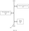
- a communication apparatus includes a processor and a transceiver.
- the processor and the transceiver are configured to implement any method provided in any one of the first aspect to the fourth aspect.
- the processor is configured to perform a processing action in the corresponding method, and the transceiver is configured to perform a receiving/sending action in the corresponding method.
- a computer-readable storage medium stores computer instructions, and when the computer instructions are run on a computer, the computer is enabled to perform any method provided in any one of the first aspect to the fourth aspect.
- a computer program product including computer instructions is provided.
- the computer instructions When the computer instructions are run on a computer, the computer is enabled to perform any method provided in any one of the first aspect to the fourth aspect.
- a chip including a processing circuit and a transceiver pin.
- the processing circuit and the transceiver pin are configured to implement any method provided in any one of the first aspect to the fourth aspect.
- the processing circuit is configured to perform a processing action in the corresponding method, and the transceiver pin is configured to perform a receiving/sending action in the corresponding method.
- A/B may represent A or B.
- a term “and/or” in this specification describes only an association relationship between associated objects and indicates that there may be three relationships.
- a and/or B may represent the following three cases: Only A exists, both A and B exist, and only B exists.
- "at least one” means one or more, and "a plurality of” means two or more. Terms such as “first” and “second” do not limit a number and an execution sequence, and the terms such as “first” and “second” do not indicate a definite difference.
- the word such as “example” or “for example” is used to represent giving an example, an illustration, or a description. Any embodiment or design scheme described as an “example” or “for example” in this application should not be explained as being more preferred or having more advantages than another embodiment or design scheme. Exactly, use of the word “example” or “for example” or the like is intended to present a related concept in a specific manner.
- the technical solutions provided in this application may be applied to various communication systems, for example, a system using the IEEE 802.11 standard.
- the IEEE 802.11 standard includes but is not limited to the 802.11be standard or a next-generation 802.11 standard.
- Application scenarios of the technical solutions of this application include communication between an AP and a STA, communication between APs, communication between STAs, and the like.
- STAs in this application may be various user terminals, user apparatuses, access apparatuses, subscriber stations, subscriber units, mobile stations, user agents, user devices, or other devices that have a wireless communication function.
- the user terminals may include various handheld devices, vehicle-mounted devices, wearable devices, computing devices that have the wireless communication function, or other processing devices connected to a wireless modem, and include various forms of user equipments (user equipments, UEs), mobile stations (mobile stations, MSs), terminals (terminals), terminal equipments (terminal equipments), portable communication devices, handheld devices, portable computing devices, entertainment devices, game devices or systems, and global positioning system devices, or any other suitable device configured to perform network communication via wireless media.
- the devices mentioned above are collectively referred to as stations or STAs.
- the access point AP in this application is an apparatus that is deployed in a wireless communication network and that provides a wireless communication function for a STA associated with the access point AP.
- the access point AP may be used as a hub of the communication system, and may be a communication device such as a base station, a router, a gateway, a repeater, a communication server, a switch, or a bridge.
- the base station may include various forms of macro base stations, micro base stations, relay stations, and the like.
- the devices mentioned above are collectively referred to as access points APs.
- the BSS is used to describe a group of devices that can communicate with each other in a wireless local area network (wireless local area network, WLAN).
- the WLAN may include a plurality of BSSs.
- Each BSS has a unique identifier, which is referred to as a basic service set identifier (BSSID).
- BSSID basic service set identifier
- one BSS may include one AP and a plurality of STAs associated with the AP.
- a TXOP is a basic unit in wireless channel access.
- the TXOP includes an initial time point and maximum duration (TXOP limit).
- TXOP limit a station that obtains the TXOP may not perform channel contention again, and continuously use a channel to transmit a plurality of data frames.
- the TXOP may be obtained through contention or hybrid coordinator (hybrid coordinator, HC) allocation.
- the TXOP obtained through contention may be referred to as an enhanced distributed channel access (enhanced distributed channel access, EDCA) TXOP.
- the TXOP obtained through HC allocation may be referred to as a hybrid coordination function controlled channel access (hybrid coordination function controlled channel access, HCCA) TXOP.
- a trigger frame In an uplink transmission process or a downlink transmission process, a trigger frame needs to be used to implement information exchange in multi-user communication.
- FIG. 1 is a schematic diagram of a frame structure of a trigger frame.
- the trigger frame includes: a frame control (frame control) field, a duration (duration) field, a receiving address (receiving address, RA) field, a transmitting address (transmitting address, TA) field, a common information (common info) field, a user information list (user info list) field, a padding (padding) field, and a frame check sequence (frame check sequence, FCS) field.
- the common information field includes common information that needs to be read by all stations.
- the common information field includes: a trigger type (trigger type) subfield, an uplink length (UL length) subfield, a more trigger frame (more TF) subfield, a carrier sense required (CS required) subfield, an uplink bandwidth (UL bandwidth) subfield, a guard interval and HE long training field type (GI and HE-LTF type) subfield, a mode (MU-MIMO HE-LTF mode) subfield, a number of HE-LTFs and midamble periodicity (number of HE-LTF symbols and Midamble periodicity) subfield, an uplink space-time block coding (UL STBC) subfield, an LDPC extra symbol segment (LDPC extra symbol segment) subfield, an AP transmit power (AP TX power) subfield, a pre-FEC padding factor (Pre-FEC padding factor) subfield, a packet extension disambiguity (PE disambiguity) subfield, an uplink spatial reuse
- the trigger type subfield occupies four bits, and indicates a type of the trigger frame.
- Table 1 Value of a trigger type field Type of a trigger frame 0 Basic (basic) 1 Beamforming report poll (Beamforming report poll, BFRP) 2 Multi-user block acknowledgment request (multi-user block ack request, MU-BAR) 3 Multi-user request to send (Multi-user Request To Send, MU-RTS) 4 Buffer status report poll (buffer status report poll, BSRP) 5 Group cast retransmission (group cast retransmission, GCR) MU-BAR 6 Bandwidth query report poll (bandwidth query report poll, BQRP) 7 NDP feedback report poll (NDP feedback report poll, NFRP) 8 to 15 Reserved
- the user information list field of the trigger frame may include a plurality of user information fields.
- a structure of the user information field may be shown in FIG. 3 .
- the user information field may include: an AID subfield, a resource block allocation (RU allocation) field, an uplink forward error correction coding type (UL FEC coding type) field, an uplink modulation and coding scheme (UL HE-MCS) field, an uplink dual-carrier modulation (UL DCM) field, a spatial stream allocation/random access RU information (SS allocation/RA-RU information) field, an uplink target received signal strength indicator (UL target RSSI) field, a reserved (reserved) field, and a trigger dependent user info (trigger dependent user info) field.
- RU allocation resource block allocation
- UL FEC coding type uplink forward error correction coding type
- UL HE-MCS uplink modulation and coding scheme
- UL DCM uplink dual-carrier modulation
- SS allocation/RA-RU information spatial stream allocation
- PPDU types are added to a physical layer in the 802.11ax: a single-user (single user, SU) PPDU, an extended range (extended range) PPDU, a multi-user (multi user, MU) PPDU, and a trigger-based (trigger-based, TB) PPDU.
- the single-user PPDU is mainly applied to a single-user scenario.
- the extended range PPDU is mainly applied to a single-user scenario far away from an AP, for example, an outdoor scenario.
- the multi-user PPDU is mainly applied to a multi-user scenario, and may be simultaneously transmitted to one or more users for one or more times.
- the TB PPDU is used to respond to a trigger frame.
- the TB PPDU is mainly transmitted in an uplink orthogonal frequency division multiple access (orthogonal frequency division multiple access, OFDMA) or uplink MU-multiple-input multiple-output (multiple in multiple out, MIMO) scenario.
- OFDMA orthogonal frequency division multiple access
- MIMO multiple in multiple out
- an A-control field includes a control identifier (control ID) field and a control information (control information) field.
- the control ID field occupies four bits. A number of bits occupied by the control information field varies according to a value (value) of the control ID field.
- TRS control 1 Operating mode (operating mode, OM) 12
- OM control 2 High-efficiency link adaptation (HE link adaptation, HLA) 26 HLA control 3
- BSR control 4 Uplink power headroom (UL power headroom, UPH) 8 UPH control 5
- control information field in the A-control field is used as a BSR control field.
- control information field in the A-control field is used as a CAS control field.
- the control information field in the A-control field is used as a TRS control field.
- the TRS control field in the conventional technology includes an uplink data symbol (UL data symbol) field, a resource block allocation (RU allocation) field, an access point transmit power (AP TX power) field, a UL target RSSI field, a UL HE-MCS field and a reserved field.
- UL data symbol uplink data symbol
- RU allocation resource block allocation
- AP TX power access point transmit power
- bits occupied by the TRS control field are sequentially sorted from a least significant bit to a most significant bit, and may be numbered B0 to B25 bits.
- the UL data symbol field occupies the B0 to B4 bits
- the RU allocation field occupies the B5 to B12 bits
- the AP TX power field occupies the B13 to B17 bits
- the UL target RSSI field occupies the B18 to B22 bits
- the UL HE-MCS field occupies the B23 and B24 bits
- the reserved field occupies the B25 bit.
- an extremely high throughput (Extremely high throughput, EHT) device supports a plurality of streams, a plurality of frequency bands (such as 2.4 GHz, 5 GHz, and 6 GHz frequency bands), cooperation of a plurality of channels in a same frequency band, and other manners, to improve a peak throughput and reduce a service transmission delay.
- the plurality of frequency bands or the plurality of channels may be collectively referred to as a multi-link.
- the multi-link device includes one or more affiliated stations, and the affiliated stations may be logical stations or physical stations.
- the multi-link device includes an affiliated station may be briefly described as “the multi-link device includes a station”.
- the affiliated station may be an access point (access point, AP) or a non-access point station (non-access point station, non-AP STA).
- access point access point
- non-access point station non-access point station
- a multi-link device whose affiliated station is an AP may be referred to as a multi-link AP, an AP MLD, or an AP multi-link device
- a multi-link device whose affiliated station is a STA may be referred to as a multi-link STA, a STA multi-link device, or a STA MLD, or a non-AP MLD.
- the multi-link device may implement wireless communication in compliance with the 802.11 system protocol.
- the 802.11 system protocol may be an 802.11ax protocol, an 802.11be protocol, or a next-generation 802.11 protocol. This is not limited in this embodiment of this application.
- the multi-link device may communicate with another device.
- the another device may be a multi-link device, or may not be a multi-link device.
- FIG. 5 is a schematic diagram of a communication scenario of an AP multi-link device and a STA multi-link device.
- one AP multi-link device may be associated with a plurality of STA multi-link devices and a single-link STA.
- an AP multi-link device 100 is associated with a STA multi-link device 200, a STA multi-link device 300, and a STA 400.
- a plurality of APs in an AP multi-link device respectively operate on a plurality of links
- a plurality of STAs in a STA multi-link device respectively operate on a plurality of links
- one STA in the STA multi-link device is associated with one AP in an AP multi-link device on an operating link of the STA.
- a single-link STA is associated with an AP in an AP multi-link device on an operating link of the STA.
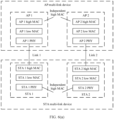
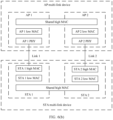
- FIG. 6(a) and FIG. 6(b) are schematic diagrams of structures of an AP multi-link device and a STA multi-link device that participate in communication.
- the 802.11 standard focuses on 802.11 physical layer (Physical layer, PHY) and media access control (Media Access Control, MAC) layer parts of an AP multi-link device and a STA multi-link device (for example, a mobile phone and a notebook computer).
- PHY Physical layer
- MAC Media Access Control
- a plurality of APs included in the AP multi-link device are independent of each other at a low MAC (low MAC) layer and a PHY layer, and are also independent of each other at a high MAC (high MAC) layer.
- a plurality of STAs included in the STA multi-link device are independent of each other at the low MAC layer and the PHY layer, and are also independent of each other at the high MAC layer.
- a plurality of APs included in the AP multi-link device are independent of each other at a low MAC layer and a PHY layer, and share a high MAC (High MAC) layer.
- a plurality of STAs included in the STA multi-link device are independent of each other at the low MAC (Low MAC) layer and the PHY layer, and share the high MAC (High MAC) layer.
- the STA multi-link device may use a structure in which high MAC layers are independent of each other, and the AP multi-link device may use a structure in which a high MAC layer is shared.
- the STA multi-link device uses a structure in which a high MAC layer is shared, and the AP multi-link device uses a structure in which high MAC layers are independent of each other.
- the high MAC layer or the low MAC layer may be implemented by one processor in a chip system of the multi-link device, or may be implemented by different processing modules in a chip system.
- a frequency band on which the multi-link device operates may include but is not limited to sub 1 GHz, 2.4 GHz, 5 GHz, 6 GHz, and a high frequency 60 GHz.
- the multi-link device may support simultaneous data transmitting and receiving (simultaneously transmit and receive, STR), or the multi-link device may not support simultaneous data transmitting and receiving. That the multi-link device supports simultaneous data transmitting and receiving means that in a process of transmitting data on one link, the multi-link device can receive data on another link. That the multi-link device does not support simultaneous data transmitting and receiving means that in a process of transmitting data on one link, the multi-link device cannot receive data on another link.
- radio frames sent by the AP in the multi-link device on a plurality of links are aligned at an end, and in addition, response frames sent by the STA multi-link device on a plurality of links are aligned at both start time and end time.
- a radio frame is needed to control a length of a response frame, to ensure that response frames transmitted on different links can be aligned.
- multi-link scenario For ease of description, the "communication scenario of a multi-link device that does not support STR" is referred to as a “multi-link scenario” for short below.
- the trigger frame defined in the current standard is not applicable to the multi-link scenario described above.
- the reasons are as follows:
- the radio frame # 1 may trigger a station to respond in a single-user PPDU manner.
- the radio frame # 1 includes an assigned time duration (assigned time duration) field.
- the assigned duration field indicates a length that is of a single-user PPDU and that is fed back by the station.
- the radio frame #1 may be referred to as a single-user trigger frame. It should be understood that the radio frame #1 may be aggregated or carried in the downlink data.
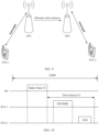
- FIG. 7 shows an application example of the radio frame #1 in the multi-link scenario.
- a transmitter sends data (data) 1 and the radio frame #1 to a receiver on a link 1, and sends data 2 and the radio frame #1 to the receiver on a link 2.
- the receiver sends a block acknowledgment (block ack, BA) frame 1 on the link 1 and sends a BA frame 2 on the link based on an indication of the single-user trigger frame. Both the BA frame 1 and the BA frame 2 are aligned in time domain.
- "Tr" represents the radio frame #1.
- IEEE802.11be standard further supports a scheduled P2P mechanism and a CO-TDMA mechanism.
- FIG. 8 is a schematic diagram of a scheduled P2P scenario.
- an AP is associated with a STA 1, and the AP may be associated with or not associated with a STA 2.
- a P2P link is established between the STA 1 and the STA 2.
- the AP may allocate a time resource to the STA 1, so that the STA 1 communicates with the STA 2 over the P2P link on the allocated time resource.
- FIG. 9 is a schematic diagram of a CO-TDMA scenario.
- an AP 1 is associated with a STA 1
- an AP 2 is associated with a STA 2.
- the AP 1 may allocate a time resource of the TXOP to the AP 2. Therefore, the AP 2 may communicate with the STA 2 on the time resource.
- this application provides a radio frame #2.
- the radio frame #2 is used to allocate the time resource.
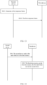
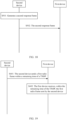
- FIG. 10 is a schematic diagram of applying the radio frame #2 to the scheduled P2P scenario.
- the AP sends the radio frame #2 to the STA 1, and the radio frame #2 allocates a time resource #1 to the STA 1. Therefore, on the time resource #1, the STA 1 may send a PPDU to the STA 2, and the STA 2 may send an ACK frame of the PPDU to the STA 1.
- FIG. 11 is a schematic diagram of applying the radio frame #2 to the CO-TDMA scenario.
- the AP 1 is a TXOP and is an owner.
- the AP 1 may send one radio frame #2 to the AP 2, to allocate a time resource #1 to the AP 2.
- the AP 2 communicates with one or more STAs associated with the AP 2.
- the radio frame #1 applied to the multi-link scenario and the radio frame #2 applied to the scheduled P2P scenario or the CO-TDMA scenario are not interchangeable. Therefore, to enable a device to identify whether a radio frame is the radio frame #1 or the radio frame #2, the radio frame #1 and the radio frame #2 need to have respective frame types, resulting in a complex communication protocol.
- an embodiment of this application provides a first frame.
- the first frame includes a first field and a second field.
- the first field indicates a duration of a first time resource.
- the second field indicates a purpose of the first time resource.
- the time resource may have another name, for example, a time period, a time domain resource, or time. This is not limited in embodiments of this application.
- the first field is different from a duration field further included in the first frame.
- the duration field is used to predetermine a period of use time of a medium.
- the first field may have another name, for example, an assigned time duration field
- the second field may have another name, for example, an assigned type (assigned type) field. This is not limited in embodiments of this application.
- the purpose of the first time resource includes: Purpose 1: The first time resource is used to transmit a single-user PPDU.
- the duration of the first time resource may be a length of the single-user PPDU.
- the duration of the first time resource may be equal to a sum of a length of the single-user PPDU, an inter-frame space (SIFS), and a length of a legacy physical layer preamble.
- SIFS inter-frame space
- the first-type scenario includes but is not limited to the multi-link scenario.
- Purpose 2 The first time resource is used to perform frame exchange.
- start time of the first time resource is time at which the receiver receives the first frame.
- the second-type scenario includes but is not limited to the scheduled P2P scenario or the CO-TDMA scenario.
- that the second field indicates the purpose of the first time resource includes one of the following cases:
- the second field occupies one bit
- the first preset value may be 0, and the second preset value may be 1.
- that the second field indicates the purpose of the first time resource includes one of the following cases:
- the cooperation device and a first device do not belong to a same BSS.
- the cooperation device may be a shared AP in the CO-TDMA scenario.
- Case 2-3 When a value of the second field is a third preset value, the second field indicates that the first time resource is used by a P2P station to perform frame exchange.
- the second field occupies two bits, the first preset value is 0, the second preset value is 1, and the third preset value is 2.
- the following describes a design manner of the first frame. It should be understood that the first frame may use any one of the following design manners.
- the first frame is a new type of trigger frame.
- the first frame includes a trigger type field whose value is a first value, and the first value is any one of 8 to 15.
- Design manner 2 The first frame is improved based on a basic trigger frame.
- the first frame includes a trigger type field whose value is 0.
- a B63 bit of the first frame is set to 1, to indicate that the basic trigger frame is the first frame.
- the B63 bit of the basic trigger frame in the current standard is a reserved bit.
- the first field and the second field may be located in a common information field or a user information field of the first frame.
- the first field when the first field and the second field are located in the common information field of the first frame, the first field may be a UL length field, and the second field may reuse another field other than the UL length field in the common information field.
- a first trigger frame includes an A-control field that uses a new control type.
- the first frame includes an A-control field, a value of a control identifier field in the A-control field is a second value, and the second value is any one of 7 to 14.
- the first field and the second field may be located in a control information field of the A-control field.
- Design manner 4 The first frame is improved based on a TRS control type in an existing A-control field.
- the first frame is a radio frame that carries the A-control field.
- a value of a control ID field in the A-control field is 0, and the A-control field includes a TRS control field.
- a B25 bit in the TRS control field is set to 1, and all or some of B0 to B24 bits in the TRS control field are used to carry the first field and the second field.
- FIG. 12 shows a communication method according to an embodiment of this application. The method includes the following steps.
- S101 A first device generates a first frame.
- the first device may be an AP or a STA.
- the first device may determine a duration of a first time resource based on an actual situation. For example, the first device may determine the duration of the first time resource based on buffer status information reported by a second device.
- the first device sends the first frame to the second device.
- the second device receives a trigger frame sent by the first device.
- S103 The second device parses the first frame.
- the second device uses, based on a second field in the first frame, the first time resource indicated by a first field.
- the second device determines, based on the second field in the first frame, that the first time resource is used to transmit a single-user PPDU. In this case, the second device sends the single-user PPDU to the first device.
- the second device determines, based on the second field in the first frame, that the first time resource is used to perform frame exchange. If the second device is an AP, the second device performs, according to a CO-TDMA mechanism and on the first time resource, frame exchange with another device associated with the second device. If the second device is a STA, the second device performs frame exchange with another P2P station according to a scheduled P2P mechanism.
- the first frame includes the first field and the second field.
- the first field indicates the duration of the first time resource.
- the second field may indicate that the first time resource is used to transmit the single-user PPDU. Alternatively, the second field indicates that the first time resource is used to perform frame exchange.
- the first frame may be applied to a scenario that has different purposes for a time resource, so that the first frame is universal.
- FIG. 13 is a flowchart of a communication method according to an embodiment of this application. As shown in FIG. 13 , the communication method includes the following steps.
- S201 The second device generates the first response frame.
- the first response frame includes a third field.
- the third field indicates that the second device accepts or rejects the first time resource. In other words, the third field indicates whether the second device accepts the first time resource.
- the third field when the third field is set to 0, the third field indicates that the second device accepts the first time resource.
- the third field indicates that the second device rejects the first time resource.
- the third field when the third field is set to 1, the third field indicates that the second device accepts the first time resource.
- the third field indicates that the second device rejects the first time resource.
- the second device sends the first response frame to the first device.
- the first device receives the first response frame sent by the second device.
- the first device may learn that the second device correctly receives the first frame.
- the first device may determine that the second device does not correctly receive the first frame.
- the first device may learn, based on whether the first response frame is received, whether the second device correctly receives the first frame.
- the first device may determine, based on the third field in the first response frame, whether the second device accepts the first time resource, so that when the second device rejects the first time resource, the first device may allocate the first time resource to another device again, thereby avoiding a waste of time resources.
- the second device may not feed back a response frame to the first device, but directly perform frame exchange with another device.
- the second device may use an embodiment shown in FIG. 14 , so that the first device learns that the second device accepts the first time resource allocated by the first device.
- FIG. 14 shows a communication method according to an embodiment of this application. The method includes the following steps.
- S301 The second device sends a first radio frame on the first time resource.
- a receiver address of the radio frame is not a MAC address of the first device.
- a frame format used by the first radio frame sent by the second device is a frame format that can be supported by the first device.
- a physical layer parameter used to send the radio frame is a physical layer parameter that can be supported by the first device.
- the physical layer parameter includes but is not limited to a number of spatial streams and an MCS.
- the MCS used to send the radio frame is less than or equal to a first MCS, and the first MCS is a maximum MCS supported by the first device.
- the MCS used to send the radio frame is less than or equal to a target MCS.
- the target MCS is a smaller value in a first MCS and a second MCS.
- the second MCS is a maximum MCS that is expected to be parsed by the first device in a current channel condition.
- S302 The first device receives, on the first time resource, the first radio frame sent by the second device.
- the first device may parse the radio frame, to learn that the second device accepts the first time resource.
- the first device may determine that the second device does not correctly receive the first frame, or the first device may determine that the second device rejects the first time resource indicated by the first field in the first frame. In this case, the first device may allocate the time resource to another device.
- the parsing capability of the first device may not be considered for another radio frame (for example, a second radio frame or a third radio frame) other than the first radio frame sent by the second device on the first time resource.
- a frame format used by the another radio frame may not be the frame format that can be supported by the first device
- a physical layer parameter used to send the another radio frame may not be the physical layer parameter that can be supported by the first device.
- RDG reverse direction grant
- an RDG initiator may transfer a remaining time of a TXOP held by the RDG initiator to an RDG responder (responder). Then, the RDG responder communicates with the RDG initiator by using a single-user PPDU. Alternatively, the RDG responder communicates with a plurality of devices by using a downlink multi-user PPDU or the trigger frame. The plurality of devices need to include the RDG initiator.
- a transmitter may send RDG indication information to a receiver, so that the receiver learns whether the transmitter transfers a remaining time of a TXOP held by the transmitter to the receiver. It should be understood that, when the transmitter transfers the remaining time of the TXOP held by the transmitter to the receiver, the transmitter is the RDG initiator, and the receiver is the RDG responder.
- an existing CAS control field includes an AC constraint (constraint) field, an RDG/more PPDU field, a parameterized spatial reuse transmission (parameterized spatial reuse transmission, PSRT) PPDU field, and five reserved bits.
- the AC constraint field, the RDG/more PPDU field, and the PSRT PPDU field each occupy one bit.
- the RDG/more PPDU field is used as the RDG indication information. Specifically, when the RDG/more PPDU field is set to 1, it indicates that the transmitter transfers the remaining time of the TXOP held by the transmitter to the receiver. When the RDG/more PPDU field is set to 0, it indicates that the transmitter does not transfer the remaining time of the TXOP held by the transmitter to the receiver.
- the AC constraint field indicates whether there is a limitation on a type of a data frame sent by the RDG responder within the remaining time of the TXOP. Specifically, when the AC constraint field is set to 0, it indicates that there is no limitation on the type of the data frame sent by the RDG responder within the remaining time of the TXOP. When the AC constraint field is set to 1, it indicates that there is a limitation on the type of the data frame sent by the RDG responder within the remaining time of the TXOP.
- That there is a limitation on the type of the data frame sent by the RDG responder specifically means that the RDG responder can send only data of a primary access category (access category, AC) corresponding to the TXOP.
- AC access category
- the PSRT PPDU field indicates that a current PPDU is a spatial reuse PPDU sent when a parameterized spatial reuse transmission condition is met.
- the IEEE802.11be standard may further support the scheduled P2P mechanism and the CO-TDMA mechanism.
- a first AP may also need to transfer a remaining time of a TXOP held by the first AP to a STA associated with the first AP.
- a first AP may also need to transfer a remaining time of a TXOP held by the first AP to a second AP.
- the RDG mechanism is not applicable to some other application scenarios (for example, the scheduled P2P scenario or the CO-TDMA scenario).
- the reason is as follows: Based on the RDG mechanism, the RDG responder needs to communicate with the RDG initiator when accepting the remaining time of the TXOP.
- the RDG responder needs to communicate with the RDG initiator when accepting the remaining time of the TXOP.
- a device that accepts the remaining time of the TXOP communicates with another device, and the another device does not include a holder of the TXOP.
- a communication protocol is complex.
- this embodiment of this application provides a second frame.
- the second frame includes an A-control field.
- the A-control field includes a CAS control field.
- the CAS control field includes a fourth field and a fifth field.
- the second frame is a data frame, for example, a quality of service (quality of service, QoS) frame or a QoS null (null) frame.
- QoS quality of service
- QoS null null
- the fourth field indicates whether to transfer the remaining time of the TXOP to the second device, so that the second device communicates with the first device within the remaining time of the TXOP. In other words, the fourth field indicates whether to transfer the remaining time of the TXOP to the RDG responder.
- the fourth field may have another name, for example, an RDG/more PPDU field.
- the fourth field when the fourth field is set to a fourth preset value, the fourth field indicates to transfer the remaining time of the TXOP to the second device, so that the second device communicates with the first device within the remaining time of the TXOP.
- the fourth field when the fourth field is set to a fifth preset value, the fourth field indicates not to transfer the remaining time of the TXOP to the second device.
- the fourth preset value is different from the fifth preset value.
- the second device communicates with the first device within the remaining time of the TXOP may be that: The second device communicates, within the remaining time of the TXOP, with the first device by using the single-user PPDU. Alternatively, the second device communicates, by using the downlink multi-user PPDU or the trigger frame within the remaining time of the TXOP, with a plurality of devices including the first device.
- Values of the fourth preset value and the fifth preset value are not limited in this embodiment of this application.
- the fourth preset value is 1, and the fifth preset value is 0.
- the fifth field indicates whether to transfer the remaining time of the TXOP to the second device, so that the second device communicates with a third device within the remaining time of the TXOP.
- the third device does not include the first device.
- the fifth field indicates whether to transfer the remaining time of the TXOP to a cooperation device or a P2P STA.
- the fifth field when the fifth field is set to a fourth preset value, the fifth field indicates to transfer the remaining time of the TXOP to the second device, so that the second device communicates with a third device within the remaining time of the TXOP.
- the fifth field when the fifth field is set to a fifth preset value, the fifth field indicates not to transfer the remaining time of the TXOP to the second device.
- the fifth field indicates to transfer the remaining time of the TXOP to the second device, so that the second device communicates with the third device within the remaining time of the TXOP, the second device does not communicate with the first device within the remaining time of the TXOP.
- the fifth field may have another name, for example, a time sharing (time sharing) field.
- the fourth field and the fifth field cannot be both set to the fourth preset value.
- the second frame further includes a duration field.
- the duration field may be used to determine a duration of the remaining time of the TXOP.
- the CAS control field further includes a sixth field.
- the sixth field indicates whether there is a limitation on a type of a data frame sent by the second device within the remaining time of the TXOP. Specifically, when the sixth field is set to 0, the sixth field indicates that there is no limitation on the type of the data frame sent by the second device within the remaining time of the TXOP. When the sixth field is set to 1, the sixth field indicates that there is a limitation on the type of the data frame sent by the second device within the remaining time of the TXOP.
- the sixth field may have another name, for example, an AC constraint field.
- the CAS control field further includes a seventh field.
- the seventh field indicates whether the second device is allowed to transfer the remaining time of the TXOP to another device. Specifically, when the seventh field is set to a sixth preset value, the seventh field indicates that the second device is not allowed to transfer the remaining time of the TXOP to the another device. When the seventh field is set to a seventh preset value, the seventh field indicates that the second device is allowed to transfer the remaining time of the TXOP to the another device.
- the seventh field may have another name, for example, a further grant field.
- the CAS control field may further include another field, for example, a PSRT PPDU field.
- FIG. 16 is a schematic diagram of a CAS control field in the second frame according to an embodiment of this application.
- the CAS control field may include a fourth field, a fifth field, a sixth field, a seventh field, a PSRT PPDU field, and three reserved bits.
- the fourth field, the fifth field, the sixth field, the seventh field, and the PSRT PPDU field each occupy one bit.
- FIG. 17 shows a communication method according to an embodiment of this application. The method includes the following steps.
- S401 A first device generates a second frame.
- the first device sends the second frame to a second device.
- the second device receives the second frame sent by the first device.
- the second device When a fourth field in a CAS control field of the second frame is set to a fourth preset value, the second device communicates with the first device within a remaining time of a TXOP.
- the second device communicates with a third device within a remaining time of a TXOP.
- the third device may be determined based on a specific application scenario.
- the third device may be a station associated with the second device.
- the third device may be a station that establishes a P2P link with the second device.
- the second frame carries the CAS control field.
- the CAS control field includes the fourth field and the fifth field.
- the fourth field indicates to transfer the remaining time of the TXOP to the second device, so that the second device communicates with the first device within the remaining time of the TXOP.
- the fifth field indicates whether to transfer the remaining time of the TXOP to the second device, so that the second device communicates with the third device within the remaining time of the TXOP.
- the third device does not include the first device.
- the second frame may be applied to an application scenario in which the remaining time of the TXOP is differently arranged, for example, a scenario to which an RDG mechanism is applied, the scheduled P2P scenario, or the CO-TDMA scenario. Therefore, the second frame is universal.
- the remaining time of the TXOP transferred by the first device to the second device by using the second frame may be briefly referred to as a second time resource.
- a remaining time of the second time resource may be briefly referred to as a third time resource.
- the second device may return the third time resource to the first device by using any one of the following operations:
- FIG. 18 is a flowchart of a communication method according to an embodiment of this application. As shown in FIG. 18 , the communication method includes the following steps.
- S501 The second device generates the second response frame.
- the second response frame is used to respond to the second frame.
- the second response frame includes an eighth field. The eighth field indicates whether the second device accepts the remaining time of the TXOP.
- the eighth field when the eighth field is set to 0, the eighth field indicates that the second device accepts the remaining time of the TXOP.
- the eighth field when the eighth field is set to 1, the eighth field indicates that the second device rejects the remaining time of the TXOP.
- the eighth field when the eighth field is set to 1, the eighth field indicates that the second device accepts the remaining time of the TXOP. Alternatively, when the eighth field is set to 0, the eighth field indicates that the second device rejects the remaining time of the TXOP.
- S502 The second device sends the second response frame to the first device.
- the first device receives the second response frame sent by the second device.
- the first device may learn, based on whether the second response frame is received, whether the second device correctly receives the second frame.
- the first device may determine, based on the eighth field in the second response frame, whether the second device accepts the remaining time of the TXOP, so that when the second device rejects the remaining time of the TXOP, the first device may allocate the remaining time of the TXOP to another device again, thereby avoiding a waste of time resources.
- the second device may not feed back a response frame to the first device, but directly perform frame exchange with another device.
- the second device uses the embodiment shown in FIG. 19 , so that the first device learns that the second device accepts the remaining time of the TXOP allocated by the first device.
- S601 The second device sends a first radio frame within the remaining time of the TXOP.
- a receiver address of the radio frame is not a MAC address of the first device.
- a frame format used by the first radio frame sent by the second device is a frame format that can be supported by the first device.
- a physical layer parameter used to send the radio frame is a physical layer parameter that can be supported by the first device.
- the physical layer parameter includes but is not limited to a number of spatial streams and an MCS.
- the MCS used to send the radio frame is less than or equal to a first MCS, and the first MCS is a maximum MCS supported by the first device.
- the first device receives, within the remaining time of the TXOP, the first radio frame sent by the second device.
- the first device may parse the radio frame, to learn that the second device accepts the remaining time of the TXOP.
- the first device may determine that the second device does not correctly receive the second frame, or the first device may determine that the second device rejects the remaining time of the TXOP. In this case, the first device may transfer the remaining time of the TXOP to another device.
- the parsing capability of the first device may not be considered for another radio frame (for example, a second radio frame or a third radio frame) other than the first radio frame sent by the second device within the remaining time of the TXOP.
- a frame format used by the another radio frame may not be the frame format that can be supported by the first device
- a physical layer parameter used to send the another radio frame may not be the physical layer parameter that can be supported by the first device.
- the second device needs to report buffer status information to the first device in advance, to assist the first device in allocating the time resource to the second device.
- FIG. 20 shows a communication method according to an embodiment of this application.
- the communication method includes the following steps.
- S701 A second device generates buffer status information.
- the buffer status information indicates a buffer data amount.
- the buffer data amount may be one or more of the following: a total uplink buffer data amount, a total downlink buffer data amount, or a sum of the total uplink buffer data amount and the total downlink buffer data amount.
- the total uplink buffer data amount is a sum of data amounts to be sent by all target stations to the second device.
- the total downlink buffer data amount is a sum of data amounts to be sent by the second device to all target stations.
- a target station is one of the following cases:
- the buffer data amount may be a sum of buffer data amounts on K P2P links established by the second device. K is a positive integer.
- the buffer data amount may be a buffer data amount on a P2P link, and the buffer status information may further include an identifier of the P2P link.
- the buffer data amount indicated by the buffer status information is a sum of buffer data amounts of all ACs or all TIDs.
- the buffer status information indicating the buffer data amount may include the following implementations:
- the AC combination includes one or more ACs.
- the buffer data amount corresponding to the AC combination is a sum of buffer data amounts corresponding to all ACs in the AC combination.
- an AC combination 1 includes an AC 1 and an AC 2
- a buffer data amount corresponding to the AC combination 1 is a sum of a buffer data amount corresponding to the AC 1 and a buffer data amount corresponding to the AC 2.
- the TID combination includes one or more TIDs.
- the buffer data amount corresponding to the TID combination is a sum of buffer data amounts corresponding to all TIDs in the TID combination.
- a TID combination 1 includes a TID 1 and a TID 2
- a buffer data amount corresponding to the TID combination 1 is a sum of a buffer data amount corresponding to the TID 1 and a buffer data amount corresponding to the TID 2.
- the second device sends the buffer status information to a first device.
- the first device receives the buffer status information sent by the second device.
- the buffer status information may be carried in a radio frame.
- the radio frame includes an A-control field.
- the A-control field includes the buffer status information. It should be understood that in this case, a value of a control ID field in the A-control field is 3, and a buffer status report field in the A-control field is equivalent to the buffer status information.
- the radio frame that carries the buffer status information is a public action (Public Action) frame.
- Public Action a public action (Public Action) frame.
- the buffer status information may use a frame structure shown in FIG. 21 or FIG. 22 .
- the buffer status information may include a feedback type (Report Type) field, a scaling factor (scaling factor) field, a total downlink buffer data amount field, a total uplink buffer data amount field, and a reserved bit.
- Report Type Report Type
- scaling factor scaling factor
- the scaling factor field indicates a scaling factor. It should be understood that, in the frame structure shown in FIG. 21 , a product of the scaling factor indicated by the scaling factor field and a data amount indicated by the total downlink buffer data amount field is the total downlink buffer data amount. A product of the scaling factor indicated by the scaling factor field and a data amount indicated by the total uplink buffer data amount field is the total uplink buffer data amount. In this way, the scaling factor field is set in the buffer status information, so that a small number of bits can be used to indicate that a data amount falls within a large value range.
- the scaling factor is an optional field. If the buffer status information does not include the scaling factor field, the total downlink buffer data amount field indicates the total downlink buffer data amount, and the total uplink buffer data amount field indicates the total uplink buffer data amount.
- the total downlink buffer data amount field may further have another name, for example, a BSS downlink queue size (queue size BSS DL) field.
- the total uplink buffer data amount field may further have another name, for example, a BSS uplink queue size (queue size BSS UL) field.
- the buffer status information may include a feedback type field, a scaling factor field, a total buffer data amount field, and a reserved bit.
- a product of a scaling factor indicated by the scaling factor field and a data amount indicated by the total buffer data amount field is the sum of the total uplink buffer data amount and the total downlink buffer data amount.
- the scaling factor is an optional field. If the buffer status information does not include the scaling factor field, the total buffer data amount field indicates the sum of the total uplink buffer data amount and the total downlink buffer data amount.
- the total buffer data amount field may have another name, for example, a queue size BSS DL + UL field.
- the buffer status information may use a frame structure shown in FIG. 23 or FIG. 24 .
- the buffer status information includes a report type field, a scaling factor field, a P2P buffer data amount field, and a reserved bit.
- a product of a scaling factor indicated by the scaling factor field and a data amount indicated by the P2P buffer data amount field is the sum of the buffer data amounts on the K P2P links established by the second device.
- the scaling factor is an optional field. If the buffer status information does not include the scaling factor field, the P2P buffer data amount field indicates the sum of the buffer data amounts on the K P2P links established by the second device.
- the buffer status information includes a report type field, a scaling factor field, a P2P buffer data amount field, a P2P end field, and a reserved bit.
- the P2P end field is used in an identifier of a P2P link.
- a product of a scaling factor indicated by the scaling factor field and a data amount indicated by the P2P buffer data amount field is a sum of buffer data that is on P2P links and that is indicated by the P2P end field.
- the scaling factor is an optional field.
- the reserved bit is optional.
- the buffer status information may not include the reserved bit.
- the feedback type field indicates a feedback type, and the feedback type includes a first feedback type and a second feedback type.
- the first feedback type indicates that the buffer status information is used in a multi-AP cooperation scenario.
- the second feedback type indicates that the buffer status information is used in a P2P scenario.
- the multi-AP cooperation scenario includes the CO-TDMA scenario.
- the first feedback type may be denoted as a plurality of APs
- the second feedback type may be denoted as a P2P.
- the feedback type field is an optional field.
- the first device may learn the feedback type of the buffer status information in any one of the following manners:
- the second device sends the buffer status information to the first device, so that the first device learns of the buffer data amount related to the second device. Further, the first device may properly allocate a time resource to the second device, so that buffer data related to the second device can be transmitted within the allocated time resource.
- FIG. 20 may be combined with the foregoing embodiment shown in FIG. 12 or FIG. 17 .
- the communication apparatus includes a corresponding hardware structure and/or software module for performing each function.
- the communication apparatus includes a corresponding hardware structure and/or software module for performing each function.
- a person skilled in the art should easily be aware that, in combination with units and algorithm steps of the examples described in embodiments disclosed in this specification, this application may be implemented by hardware or a combination of hardware and computer software. Whether a function is performed by hardware or hardware driven by computer software depends on particular applications and design constraints of the technical solutions. A person skilled in the art may use different methods to implement the described functions for each particular application, but it should not be considered that this implementation goes beyond the scope of this application.
- the apparatus may be divided into functional modules based on the foregoing method examples.
- each functional module may be obtained through division based on each corresponding function, or two or more functions may be integrated into one functional module.
- the integrated module may be implemented in a form of hardware, or may be implemented in a form of a software functional module.
- module division is an example, and is merely a logical function division. During actual implementation, another division manner may be used.
- An example in which each functional module is obtained through division based on each corresponding function is used below for description.
- FIG. 25 shows a communication apparatus according to an embodiment of this application.
- the communication apparatus includes a processing module 101 and a communication module 102.
- the processing module 101 is configured to perform the step S101 in FIG. 12 and/or the step S401 in FIG. 17 .
- the communication module 102 is configured to perform the step S102 in FIG. 12 , the step S202 in FIG. 13 , the step S302 in FIG. 14 , the step S402 in FIG. 17 , the step S502 in FIG. 18 , the step S602 in FIG. 19 , and/or the step S702 in FIG. 20 .
- the processing module 101 is configured to perform the step S103 in FIG. 12 , the step S201 in FIG. 13 , the step S403 in FIG. 17 , the step S501 in FIG. 18 , and/or the step S701 in FIG. 20 .
- the communication module 102 is configured to perform the step S102 in FIG. 12 , the step S202 in FIG. 13 , the step S301 in FIG. 14 , the step S402 in FIG. 17 , the step S502 in FIG. 18 , the step S601 in FIG. 19 , and/or the step S702 in FIG. 20 .
- FIG. 26 is a diagram of a structure of a possible product form of a communication apparatus according to an embodiment of this application.
- the communication apparatus in this embodiment of this application may be the foregoing first device.
- the first device includes a processor 201 and a transceiver 202.
- the communication device further includes a storage medium 203.
- the processor 201 is configured to perform the step S101 in FIG. 12 and/or the step S401 in FIG. 17 .
- the transceiver 202 is configured to perform the step S102 in FIG. 12 , the step S202 in FIG. 13 , the step S302 in FIG. 14 , the step S402 in FIG. 17 , the step S502 in FIG. 18 , the step S602 in FIG. 19 , and/or the step S702 in FIG. 20 .
- the communication apparatus in this embodiment of this application may be the foregoing second device.
- the second device includes a processor 201 and a transceiver 202.
- the communication device further includes a storage medium 203.
- the processor 201 is configured to perform the step S103 in FIG. 12 , the step S201 in FIG. 13 , the step S403 in FIG. 17 , the step S501 in FIG. 18 , and/or the step S701 in FIG. 20 .
- the transceiver 202 is configured to perform the step S102 in FIG. 12 , the step S202 in FIG. 13 , the step S301 in FIG. 14 , the step S402 in FIG. 17 , the step S502 in FIG. 18 , the step S601 in FIG. 19 , and/or the step S702 in FIG. 20 .
- the communication apparatus in this embodiment of this application may be implemented by a chip.
- the chip includes a processing circuit 201 and a transceiver pin 202.
- the chip may further include a storage medium 203.
- the communication apparatus in this embodiment of this application may alternatively be implemented by using the following circuit or component: one or more field programmable gate arrays (field programmable gate arrays, FPGAs), a programmable logic device (programmable logic device, PLD), a controller, a state machine, gate logic, a discrete hardware component, any other suitable circuits, or any combination of circuits that can perform various functions described in this application.
- field programmable gate arrays field programmable gate arrays
- PLD programmable logic device
- controller a state machine, gate logic, a discrete hardware component, any other suitable circuits, or any combination of circuits that can perform various functions described in this application.
- an embodiment of this application further provides a computer-readable storage medium.
- the computer-readable storage medium stores computer instructions.
- the computer instructions When the computer instructions are run on a computer, the computer is enabled to perform the communication method in the foregoing method embodiments.
- an embodiment of this application further provides a computer program product including computer instructions.
- the computer instructions When the computer instructions are run on a computer, the computer is enabled to perform the communication method in the foregoing method embodiments.
- the computer instructions may be stored in a computer-readable storage medium or may be transmitted from a computer-readable storage medium to another computer-readable storage medium.
- the computer instructions may be transmitted from a website, computer, server, or data center to another website, computer, server, or data center in a wired (for example, a coaxial cable, an optical fiber, or a digital subscriber line) or wireless (for example, infrared, radio, or microwave) manner.
- the computer-readable storage medium may be any usable medium accessible by a computer, or a data storage device, such as a server or a data center, integrating one or more usable media.
- the usable medium may be a magnetic medium (for example, a floppy disk, a hard disk, or a magnetic tape), an optical medium, a semiconductor medium (for example, a solid-state drive), or the like.
- the apparatus and method disclosed in the several embodiments provided in this application may be implemented in other manners.
- the described apparatus embodiments are merely examples.
- division into modules or units is merely logical function division and may be other division during actual implementation.
- a plurality of units or components may be combined or integrated into another apparatus, or some features may be ignored or not performed.
- the displayed or discussed mutual couplings or direct couplings or communication connections may be implemented through some interfaces.
- the indirect couplings or communication connections between the apparatuses or units may be implemented in electrical, mechanical, or another form.
- the units described as separate parts may or may not be physically separate, and parts displayed as units may be one or more physical units, may be located in one place, or may be distributed on different places. Some or all of the units may be selected based on an actual requirement to achieve the objectives of the solutions of embodiments.
- functional units in embodiments of this application may be integrated into one processing unit, or each of the units may exist alone physically, or two or more units may be integrated into one unit.
- the integrated unit may be implemented in a form of hardware, or may be implemented in a form of a software functional unit.
- the integrated unit When the integrated unit is implemented in the form of the software functional unit and sold or used as an independent product, the integrated unit may be stored in a readable storage medium.
- the software product is stored in a storage medium and includes several instructions for instructing a device (which may be a single-chip microcomputer, a chip, or the like) or a processor (processor) to perform all or some of the steps of the methods described in embodiments of this application.
Landscapes
- Engineering & Computer Science (AREA)
- Computer Networks & Wireless Communication (AREA)
- Signal Processing (AREA)
- Quality & Reliability (AREA)
- Mobile Radio Communication Systems (AREA)
Applications Claiming Priority (2)
| Application Number | Priority Date | Filing Date | Title |
|---|---|---|---|
| CN202010889093.3A CN114125854B (zh) | 2020-08-28 | 2020-08-28 | 通信方法及装置 |
| PCT/CN2021/114554 WO2022042608A1 (zh) | 2020-08-28 | 2021-08-25 | 通信方法及装置 |
Publications (2)
| Publication Number | Publication Date |
|---|---|
| EP4199567A1 true EP4199567A1 (de) | 2023-06-21 |
| EP4199567A4 EP4199567A4 (de) | 2024-02-07 |
Family
ID=80354666
Family Applications (1)
| Application Number | Title | Priority Date | Filing Date |
|---|---|---|---|
| EP21860443.7A Pending EP4199567A4 (de) | 2020-08-28 | 2021-08-25 | Kommunikationsverfahren und -vorrichtung |
Country Status (9)
| Country | Link |
|---|---|
| US (1) | US20230209518A1 (de) |
| EP (1) | EP4199567A4 (de) |
| JP (1) | JP7513238B2 (de) |
| KR (1) | KR20230051260A (de) |
| CN (1) | CN114125854B (de) |
| AU (1) | AU2021334701B2 (de) |
| CA (1) | CA3192800A1 (de) |
| MX (1) | MX2023002473A (de) |
| WO (1) | WO2022042608A1 (de) |
Families Citing this family (4)
| Publication number | Priority date | Publication date | Assignee | Title |
|---|---|---|---|---|
| CN116193621B (zh) * | 2021-01-15 | 2024-01-30 | 华为技术有限公司 | 传输机会的使用权恢复方法及相关装置 |
| KR20240023232A (ko) * | 2021-07-01 | 2024-02-20 | 후아웨이 테크놀러지 컴퍼니 리미티드 | 버퍼링된 데이터를 보고하는 방법 및 장치 |
| CN118786640A (zh) * | 2023-02-03 | 2024-10-15 | 北京小米移动软件有限公司 | 通信方法、电子设备及存储介质 |
| WO2025198246A1 (ko) * | 2024-03-22 | 2025-09-25 | 엘지전자 주식회사 | 상향링크 프레임에 적용되는 개선된 변조 기법 |
Family Cites Families (9)
| Publication number | Priority date | Publication date | Assignee | Title |
|---|---|---|---|---|
| US9991995B2 (en) * | 2014-10-06 | 2018-06-05 | Newracom, Inc. | Multiuser signaling and access request mechanisms |
| EP3588888B1 (de) * | 2014-12-05 | 2021-03-10 | Lg Electronics Inc. | Datenübertragungsverfahren in drahtloskommunikationssystem und vorrichtung dafür |
| US20180007712A1 (en) * | 2015-01-09 | 2018-01-04 | Interdigital Patent Holdings, Inc. | Methods, apparatuses and systems for supporting multi-user transmissions in a wireless local area network (wlan) system |
| US10153820B2 (en) * | 2015-11-25 | 2018-12-11 | Newracom, Inc. | Receiver address field for multi-user transmissions in WLAN systems |
| SG11201810184QA (en) * | 2016-07-22 | 2018-12-28 | Panasonic Ip Corp America | Transmission appratus and transmission method |
| EP3313142B1 (de) * | 2016-10-24 | 2019-06-19 | Lg Electronics Inc. | Verfahren zum senden oder empfangen eines rahmens in einem wlan-system und vorrichtung dafür |
| CN109121190B (zh) * | 2017-06-26 | 2022-07-12 | 珠海市魅族科技有限公司 | 无线局域网的通信方法、装置、接入点设备和站点设备 |
| CN109245851B (zh) * | 2017-07-11 | 2022-11-15 | 中兴通讯股份有限公司 | 一种无线帧传输的方法与装置 |
| CN116405159A (zh) * | 2018-07-17 | 2023-07-07 | 华为技术有限公司 | 一种通信方法及装置 |
-
2020
- 2020-08-28 CN CN202010889093.3A patent/CN114125854B/zh active Active
-
2021
- 2021-08-25 MX MX2023002473A patent/MX2023002473A/es unknown
- 2021-08-25 EP EP21860443.7A patent/EP4199567A4/de active Pending
- 2021-08-25 AU AU2021334701A patent/AU2021334701B2/en active Active
- 2021-08-25 KR KR1020237008822A patent/KR20230051260A/ko active Pending
- 2021-08-25 JP JP2023512148A patent/JP7513238B2/ja active Active
- 2021-08-25 WO PCT/CN2021/114554 patent/WO2022042608A1/zh not_active Ceased
- 2021-08-25 CA CA3192800A patent/CA3192800A1/en active Pending
-
2023
- 2023-02-28 US US18/176,263 patent/US20230209518A1/en active Pending
Also Published As
| Publication number | Publication date |
|---|---|
| JP7513238B2 (ja) | 2024-07-09 |
| MX2023002473A (es) | 2023-05-17 |
| AU2021334701A1 (en) | 2023-03-23 |
| KR20230051260A (ko) | 2023-04-17 |
| JP2023539129A (ja) | 2023-09-13 |
| EP4199567A4 (de) | 2024-02-07 |
| WO2022042608A9 (zh) | 2022-04-07 |
| AU2021334701B2 (en) | 2024-07-18 |
| CN114125854B (zh) | 2025-03-11 |
| CA3192800A1 (en) | 2022-03-03 |
| CN114125854A (zh) | 2022-03-01 |
| US20230209518A1 (en) | 2023-06-29 |
| WO2022042608A1 (zh) | 2022-03-03 |
Similar Documents
| Publication | Publication Date | Title |
|---|---|---|
| US10206070B2 (en) | Space division multiple access for wireless LAN, and channel estimation for the same | |
| JP2022111242A (ja) | 通信装置、通信方法および集積回路 | |
| US10542557B2 (en) | System and method for digital communications with interference avoidance | |
| EP2420034B1 (de) | Verfahren und vorrichtung zur verarbeitung von multicast-frames | |
| AU2021334701B2 (en) | Communication method and apparatus | |
| EP3606271B1 (de) | Verfahren zur übertragung eines rahmens auf basis mehrerer kanalisierter kanäle in einem drahtlosen lan-system und drahtloses endgerät mit verwendung davon | |
| EP3972177B1 (de) | Ppdu-sendeverfahren und empfangsverfahren sowie kommunikationsvorrichtung | |
| CN108886712B (zh) | 支持多用户级联传输的无线通信方法和使用该方法的无线通信终端 | |
| US9992765B2 (en) | Method for transmitting and receiving a frame in a wireless LAN system and apparatus for supporting same | |
| JP2012070090A (ja) | 無線通信装置 | |
| EP4475575A1 (de) | Verfahren, vorrichtung und system zur sidelink-verwaltung | |
| WO2022012561A1 (zh) | 数据传输方法及装置 | |
| CN108476476B (zh) | 功率指示系统和方法 | |
| US10582449B2 (en) | Intra-PDDU power saving in WLAN | |
| US12615677B2 (en) | Communication apparatus, communication control method, communication method, and computer-readable storage medium | |
| EP3391700B1 (de) | Vorrichrungen und verfahren zur anzeige periodischer zuweisungen | |
| TW202529479A (zh) | 靈活控制訊框 |
Legal Events
| Date | Code | Title | Description |
|---|---|---|---|
| STAA | Information on the status of an ep patent application or granted ep patent |
Free format text: STATUS: THE INTERNATIONAL PUBLICATION HAS BEEN MADE |
|
| PUAI | Public reference made under article 153(3) epc to a published international application that has entered the european phase |
Free format text: ORIGINAL CODE: 0009012 |
|
| STAA | Information on the status of an ep patent application or granted ep patent |
Free format text: STATUS: REQUEST FOR EXAMINATION WAS MADE |
|
| 17P | Request for examination filed |
Effective date: 20230316 |
|
| AK | Designated contracting states |
Kind code of ref document: A1 Designated state(s): AL AT BE BG CH CY CZ DE DK EE ES FI FR GB GR HR HU IE IS IT LI LT LU LV MC MK MT NL NO PL PT RO RS SE SI SK SM TR |
|
| DAV | Request for validation of the european patent (deleted) | ||
| DAX | Request for extension of the european patent (deleted) | ||
| REG | Reference to a national code |
Ref country code: DE Ref legal event code: R079 Free format text: PREVIOUS MAIN CLASS: H04W0016020000 Ipc: H04W0072044600 |
|
| A4 | Supplementary search report drawn up and despatched |
Effective date: 20240108 |
|
| RIC1 | Information provided on ipc code assigned before grant |
Ipc: H04W 84/12 20090101ALN20240102BHEP Ipc: H04W 72/0446 20230101AFI20240102BHEP |
|
| RAP1 | Party data changed (applicant data changed or rights of an application transferred) |
Owner name: NOKIA TECHNOLOGIES OY |