EP4199620A1 - Downlink-übertragungsverfahren und kommunikationsvorrichtung - Google Patents
Downlink-übertragungsverfahren und kommunikationsvorrichtung Download PDFInfo
- Publication number
- EP4199620A1 EP4199620A1 EP21859935.5A EP21859935A EP4199620A1 EP 4199620 A1 EP4199620 A1 EP 4199620A1 EP 21859935 A EP21859935 A EP 21859935A EP 4199620 A1 EP4199620 A1 EP 4199620A1
- Authority
- EP
- European Patent Office
- Prior art keywords
- network element
- moment
- service packet
- downlink service
- delay
- Prior art date
- Legal status (The legal status is an assumption and is not a legal conclusion. Google has not performed a legal analysis and makes no representation as to the accuracy of the status listed.)
- Pending
Links
- 238000000034 method Methods 0.000 title claims abstract description 189
- 238000004891 communication Methods 0.000 title claims abstract description 95
- 230000005540 biological transmission Effects 0.000 title claims abstract description 65
- 238000012545 processing Methods 0.000 claims description 86
- 230000015654 memory Effects 0.000 claims description 78
- 238000004590 computer program Methods 0.000 claims description 17
- 238000007726 management method Methods 0.000 description 92
- 230000006870 function Effects 0.000 description 47
- 230000008569 process Effects 0.000 description 35
- 238000010586 diagram Methods 0.000 description 21
- 230000003139 buffering effect Effects 0.000 description 13
- 230000001360 synchronised effect Effects 0.000 description 8
- 238000012517 data analytics Methods 0.000 description 6
- 230000009471 action Effects 0.000 description 4
- 238000013523 data management Methods 0.000 description 4
- 230000003068 static effect Effects 0.000 description 4
- 230000008878 coupling Effects 0.000 description 3
- 238000010168 coupling process Methods 0.000 description 3
- 238000005859 coupling reaction Methods 0.000 description 3
- ORQBXQOJMQIAOY-UHFFFAOYSA-N nobelium Chemical compound [No] ORQBXQOJMQIAOY-UHFFFAOYSA-N 0.000 description 3
- 238000012546 transfer Methods 0.000 description 3
- 230000003190 augmentative effect Effects 0.000 description 2
- 238000005516 engineering process Methods 0.000 description 2
- CNQCVBJFEGMYDW-UHFFFAOYSA-N lawrencium atom Chemical compound [Lr] CNQCVBJFEGMYDW-UHFFFAOYSA-N 0.000 description 2
- 230000007774 longterm Effects 0.000 description 2
- 230000006855 networking Effects 0.000 description 2
- 230000003287 optical effect Effects 0.000 description 2
- 230000000737 periodic effect Effects 0.000 description 2
- 239000007787 solid Substances 0.000 description 2
- 238000013475 authorization Methods 0.000 description 1
- 230000006399 behavior Effects 0.000 description 1
- 230000009286 beneficial effect Effects 0.000 description 1
- 238000004422 calculation algorithm Methods 0.000 description 1
- 238000004364 calculation method Methods 0.000 description 1
- 238000006243 chemical reaction Methods 0.000 description 1
- 239000003795 chemical substances by application Substances 0.000 description 1
- 239000013256 coordination polymer Substances 0.000 description 1
- 238000013500 data storage Methods 0.000 description 1
- 230000001934 delay Effects 0.000 description 1
- 238000013461 design Methods 0.000 description 1
- 230000004069 differentiation Effects 0.000 description 1
- 230000004048 modification Effects 0.000 description 1
- 238000012986 modification Methods 0.000 description 1
- 239000013307 optical fiber Substances 0.000 description 1
- 238000013439 planning Methods 0.000 description 1
- 239000004065 semiconductor Substances 0.000 description 1
- 230000007480 spreading Effects 0.000 description 1
Images





Classifications
-
- H—ELECTRICITY
- H04—ELECTRIC COMMUNICATION TECHNIQUE
- H04W—WIRELESS COMMUNICATION NETWORKS
- H04W72/00—Local resource management
- H04W72/50—Allocation or scheduling criteria for wireless resources
- H04W72/54—Allocation or scheduling criteria for wireless resources based on quality criteria
- H04W72/542—Allocation or scheduling criteria for wireless resources based on quality criteria using measured or perceived quality
-
- H—ELECTRICITY
- H04—ELECTRIC COMMUNICATION TECHNIQUE
- H04L—TRANSMISSION OF DIGITAL INFORMATION, e.g. TELEGRAPHIC COMMUNICATION
- H04L47/00—Traffic control in data switching networks
- H04L47/10—Flow control; Congestion control
- H04L47/28—Flow control; Congestion control in relation to timing considerations
- H04L47/283—Flow control; Congestion control in relation to timing considerations in response to processing delays, e.g. caused by jitter or round trip time [RTT]
-
- H—ELECTRICITY
- H04—ELECTRIC COMMUNICATION TECHNIQUE
- H04L—TRANSMISSION OF DIGITAL INFORMATION, e.g. TELEGRAPHIC COMMUNICATION
- H04L47/00—Traffic control in data switching networks
- H04L47/50—Queue scheduling
- H04L47/56—Queue scheduling implementing delay-aware scheduling
-
- H—ELECTRICITY
- H04—ELECTRIC COMMUNICATION TECHNIQUE
- H04W—WIRELESS COMMUNICATION NETWORKS
- H04W56/00—Synchronisation arrangements
- H04W56/0055—Synchronisation arrangements determining timing error of reception due to propagation delay
-
- H—ELECTRICITY
- H04—ELECTRIC COMMUNICATION TECHNIQUE
- H04W—WIRELESS COMMUNICATION NETWORKS
- H04W72/00—Local resource management
- H04W72/04—Wireless resource allocation
- H04W72/044—Wireless resource allocation based on the type of the allocated resource
- H04W72/0446—Resources in time domain, e.g. slots or frames
-
- H—ELECTRICITY
- H04—ELECTRIC COMMUNICATION TECHNIQUE
- H04W—WIRELESS COMMUNICATION NETWORKS
- H04W72/00—Local resource management
- H04W72/12—Wireless traffic scheduling
- H04W72/1263—Mapping of traffic onto schedule, e.g. scheduled allocation or multiplexing of flows
- H04W72/1273—Mapping of traffic onto schedule, e.g. scheduled allocation or multiplexing of flows of downlink data flows
-
- H—ELECTRICITY
- H04—ELECTRIC COMMUNICATION TECHNIQUE
- H04L—TRANSMISSION OF DIGITAL INFORMATION, e.g. TELEGRAPHIC COMMUNICATION
- H04L47/00—Traffic control in data switching networks
- H04L47/10—Flow control; Congestion control
- H04L47/34—Flow control; Congestion control ensuring sequence integrity, e.g. using sequence numbers
Definitions
- the registration request may carry a cell ID and the configuration information of the radio resource, or carry a cell ID, a terminal device ID, and the configuration information of the radio resource.
- the session management network element may obtain the configuration information of the radio resource from the mobility management network element.
- the access network element may perform semi-persistent scheduling on the downlink service packet based on a periodicity of the downlink service packet and the moment at which the downlink service packet arrives at the access network element, that is, allocate, to the downlink service packet once, a same time-frequency resource that can be periodically and repeatedly used, to reduce an end-to-end transmission delay of the downlink service packet and save a control plane resource.
- a downlink transmission method includes: A user plane network element receives, from a session management network element, time adjustment information related to a first delay, where the first delay is duration between an expected moment at which a downlink service packet arrives at an access network element and an estimated moment at which the downlink service packet arrives at the access network element, the expected moment at which the downlink service packet arrives at the access network element is within a first scheduling window, and a next scheduling window adjacent to the first scheduling window is a downlink scheduling window.
- the application network element may adjust, based on the time adjustment information provided by the session management network element, a moment at which the application server sends the downlink service packet, so that when the downlink service packet is sent at an adjusted sending moment, the moment at which the downlink service packet arrives at the access network element may be within the first scheduling window of the access network element, the downlink service packet may be scheduled in a second downlink scheduling window, and the second downlink scheduling window is the next scheduling window adjacent to the first scheduling window.
- This helps reduce a scheduling waiting delay of scheduling the downlink service by the access network element, and helps guarantee an end-to-end delay of the downlink service packet.
- the time adjustment information includes one or more of the following: the first delay, an expected moment that is determined based on the first delay and at which the downlink service packet arrives at a user plane network element, and an expected moment that is determined based on the first delay and at which the downlink service packet arrives at a terminal device.
- a downlink transmission method includes: An access network element receives, from a session management network element, an estimated moment at which a downlink service packet arrives at the access network element.
- the configuration information of the radio resource includes a slot start moment, slot duration, an uplink-downlink slot configuration, and a scheduling processing delay of the access network element.
- a downlink transmission method includes: An access network element receives, from a session management network element, an estimated moment at which a downlink service packet arrives at the access network element.
- the access network element determines time adjustment information based on the estimated moment at which the downlink service packet arrives at the access network element and configuration information of a radio resource.
- the access network element sends the time adjustment information to the session management network element, where the time adjustment information is used by the session management network element to adjust a moment at which a user plane network element sends the downlink service packet and/or a moment at which an application server sends the downlink service packet.
- a moment at which the downlink service packet arrives at the access network element may be within a first scheduling window of the access network element, the downlink service packet may be scheduled in a second downlink scheduling window, and the second downlink scheduling window is a next scheduling window adjacent to the first scheduling window.
- This helps reduce a scheduling waiting delay of scheduling the downlink service by the access network element, and helps guarantee an end-to-end delay requirement of the downlink service packet.
- the access network element determines time adjustment information based on the estimated moment at which the downlink service packet arrives at the access network element and configuration information of a radio resource includes: The access network element determines a first delay based on the estimated moment at which the downlink service packet arrives at the access network element and the configuration information of the radio resource, where the first delay is duration between a moment that is expected by the access network element and at which the downlink service packet arrives at the access network element and the estimated moment at which the downlink service packet arrives at the access network element, the moment that is expected by the access network element and at which the downlink service packet arrives at the access network element is within a first scheduling window, and a next scheduling window adjacent to the first scheduling window is a downlink scheduling window.
- the access network element determines the time adjustment information based on the first delay.
- the access network element determines time adjustment information based on the estimated moment at which the downlink service packet arrives at the access network element and configuration information of a radio resource includes: The access network element determines, based on the estimated moment at which the downlink service packet arrives at the access network element and the configuration information of the radio resource, an estimated second downlink scheduling window for the access network element to schedule the downlink service packet. The access network element determines a boundary of a third scheduling window based on the second downlink scheduling window, where the third scheduling window is a scheduling window previous to the second downlink scheduling window. The access network element determines the time adjustment information based on the boundary of the third scheduling window.
- the method further includes: The session management network element receives second information from the user plane network element, where the second information is the first moment or a waiting delay of the downlink service packet on the user plane network element.
- the session management network element determines the third moment based on the second information.
- the session management network element sends the third moment to the access network element.
- the configuration information of the radio resource includes a slot start moment, slot duration, an uplink-downlink slot configuration, and a scheduling processing delay of the access network element.
- the method further includes: The user plane network element sends second information to the session management network element, where the second information is the first moment or a waiting delay of the downlink service on the user plane network element, and the second information is for determining the third moment.
- a communication apparatus includes modules or units configured to perform the method according to any one of the first aspect to the seventh aspect or the possible implementations of the first aspect to the seventh aspect.
- an apparatus includes a processor.
- the processor is coupled to a memory, and may be configured to execute instructions in the memory, so that the apparatus performs the method according to any one of the first aspect to the seventh aspect or the possible implementations of the first aspect to the seventh aspect.
- the apparatus further includes the memory.
- the apparatus further includes an interface circuit, and the processor is coupled to the interface circuit.
- a processor includes an input circuit, an output circuit, and a processing circuit.
- the processing circuit is configured to receive a signal through the input circuit, and transmit a signal through the output circuit, so that the processor performs the method according to any one of the first aspect to the seventh aspect or the possible implementations of the first aspect to the seventh aspect.
- the processing apparatus may be a chip.
- the processor may be implemented by using hardware or software.
- the processor may be a logic circuit, an integrated circuit, or the like; or when the processor is implemented by using software, the processor may be a general-purpose processor, and is implemented by reading software code stored in the memory.
- the memory may be integrated into the processor, or may exist independently outside the processor.
- a computer program product includes a computer program (also referred to as code or instructions).
- a computer program also referred to as code or instructions.
- a computer is enabled to perform the method according to any one of the first aspect to the seventh aspect or the possible implementations of the first aspect to the seventh aspect.
- the technical solutions in embodiments of this application may be applied to various communication systems, for example, a long term evolution (long term evolution, LTE) system, a 5th generation (5th generation, 5G) system, a new radio (new radio, NR) system, or another communication system that may appear in the future.
- LTE long term evolution
- 5th generation 5th generation
- NR new radio
- the terminal device 101 may be user equipment (user equipment, UE), a user, an access terminal, a subscriber unit, a subscriber station, a mobile station, a remote station, a remote terminal, a mobile device, a user terminal, a terminal, a wireless communication device, a user agent, or a user apparatus, for example, may be a mobile phone (mobile phone), a tablet (pad), a computer having a wireless transceiver function, a virtual reality (virtual reality, VR) terminal device, an augmented reality (augmented reality, AR) terminal device, a wireless terminal in industrial control (industrial control), a wireless terminal in self driving (self driving), a wireless terminal in a telemedicine (telemedicine), a wireless terminal in a smart grid (smart grid), a wireless terminal in transportation safety (transportation safety), a wireless terminal in a smart city (smart city), a wireless terminal in a smart home (smart home), and the like.
- the terminal device 110 may alternatively be an apparatus or a circuit
- the access network element 102 can manage a radio resource, provide an access service for the terminal device, and further complete forwarding of a control signal and user data between the terminal device and a core network.
- the access network element 102 may be a transmission reception point (transmission reception point, TRP), may be an evolved NodeB (evolved NodeB, eNB or eNodeB) in an LTE system, may be a home base station. (for example, home evolved NodeB or home NodeB, HNB) or a base band unit (base band unit, BBU), or may be a radio controller in a cloud radio access network (cloud radio access network, CRAN) scenario.
- TRP transmission reception point
- eNB evolved NodeB
- eNodeB evolved NodeB
- eNB evolved NodeB
- eNodeB evolved NodeB
- eNodeB evolved NodeB
- eNodeB evolved NodeB
- BBU base band unit
- CRAN cloud radio access network
- the access network device may be a relay station, an access point, a vehicle-mounted device, a wearable device, an access network device in a 5G network, an access network device in a future evolved public land mobile network (public land mobile network, PLMN), or the like, may be an access point (access point, AP) in a WLAN, or may be a gNB in a new radio (new radio, NR) system. This is not limited in embodiments of this application.
- the access network device may include a central unit (central unit, CU) node, a distributed unit (distributed unit, DU) node, an access network device including a CU node and a DU node, or an access network device including a CU-control plane node (CU-CP node), a CU-user plane node (CU-UP node), and a DU node.
- CU central unit
- DU distributed unit
- CU-UP node CU-user plane node
- DU node a CU-control plane node
- the user plane network element 103 is mainly responsible for processing a user packet, for example, forwarding and charging.
- the data network 104 is a carrier network that provides a data transmission service for a user, for example, an IP multimedia service (IP Multimedia Service, IMS) or the Internet.
- the DN may include an application server (application server, AS).
- AS application server
- the AS is a software framework, provides an environment in which an application program is run, and is configured to provide the application program with services such as security, data, transaction support, load balancing, and large-scale distributed system management.
- the terminal device obtains an application packet by communicating with the AS.
- the AF is a control plane of the AS.
- the access and mobility management network element 105 is mainly responsible for mobility management in a mobile network, for example, user location update, user network registration, and user handover.
- the session management network element 106 is mainly responsible for session management in the mobile network, for example, session establishment, modification, and release. Specific functions may be, for example, allocating an IP address to the user and selecting a user plane network element that provides a packet forwarding function.
- the policy control network element 107 is responsible for providing the access and mobility management network element and the session management network element with policies such as a quality of service (quality of service, QoS) policy and a slice selection policy.
- QoS quality of service
- the application network element 108 is responsible for providing a service for a 3GPP network, interacting with the policy control network element to perform policy control, and the like.
- the unified data management network element 109 is configured to store user data such as subscription information and authentication/authorization information.
- the network exposure network element 110 provides a framework, authentication, and an interface that are related to network capability exposure, and transfers information between a 5G system network function and another network function.
- devices or network elements may be apparatuses with corresponding functions, or may be software/hardware modules (for example, chips) inside the apparatuses, or the like. It should be further understood that any device or network element in this application may be implemented in a form of software or a combination of software and hardware.
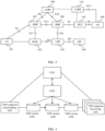
- the system 100 shown in FIG. 1 may be a 5G system shown in FIG. 2 . It should be understood that the system 100 may alternatively be a 4G system or another system. This is not limited in this application.
- FIG. 2 is a schematic diagram of an architecture of a 5G system.
- a network element that has a same reference numeral as that in FIG. 1 is a name of a corresponding network element in FIG. 1 in the current 5G system.
- the architecture of the 5G system may include one or more of the following network elements: UE 101, a (radio) access network ((radio) access network, (R)AN) 102, a user plane function (user plane function, UPF) 103, a data network (data network, DN) 104, an access and mobility management function (access and mobility management function, AMF) 105, a session management function (Session Management Function, SMF) 106, a policy control function (policy control function, PCF) 107, an application function (application function, AF) 108, a unified data management (unified data management, UDM) 109, and a network exposure function (network exposure function) 110.
- UE 101 a (radio) access network ((radio) access network, (R)AN) 102
- a user plane function user plane function, UPF
- data network data network
- DN data network
- AMF access and mobility management function
- AMF access and mobility management function
- SMF Session Management
- a name of each network element shown in FIG. 2 is merely a name, and the name constitutes no limitation on a function of the network element.
- the foregoing network elements may alternatively have other names. This is not specifically limited in embodiments of this application.
- some or all of the foregoing network elements may still use terms in 5G, or may have other names.
- a general description is provided herein. Details are not described again below.
- interfaces between the network elements shown in FIG. 2 are merely an example. In a 5G network and another future network, interfaces between network elements may alternatively not be the interfaces shown in the figure. This is not limited in this application.
- a communication system to which this application is applicable may include more or fewer network elements or devices.
- the devices or the network elements in FIG. 2 may be hardware, or may be software obtained through function division or a combination of the hardware and the software.
- the devices or the network elements in FIG. 2 may communicate with each other by using another device or network element.
- TSN time sensitive networking
- the TSN is based on layer 2 transmission, and includes a TSN switch node (also referred to as a TSN bridge) and a TSN endpoint (end station or endpoint). Different from layer 2 forwarding, the TSN switch node does not forward a packet based on a media access control address (media access control address, MAC address) learning, but forwards the packet according to a forwarding rule configured or created on the TSN switch node.
- a TSN flow is unidirectional. For the TSN flow, TSN endpoints are classified into a transmitting end (Talker) and receiving end (Listener).
- the TSN standard defines behavior of the TSN switch node and the TSN endpoint and a scheduling manner in which the TSN switch node forwards a data flow, to implement reliable-delay transmission.
- the TSN switch node uses a destination MAC address of the packet as an identifier of the data flow, and performs resource reservation and scheduling planning based on a delay requirement of a service flow, to guarantee reliability and a transmission delay according to a generated scheduling policy.
- FIG. 3 is a schematic diagram of a TSN centralized management architecture.
- the architecture includes TSN endpoints (Talker/Listener), TSN switch nodes, and control plane network elements.
- the control plane network elements include a centralized user configuration (centralized user configuration, CUC) and a centralized network configuration (centralized network configuration, CNC). Details are as follows.
- the TSN switch node reserves a resource for the data flow according to a definition of TSN, and schedules and forwards a data packet.
- the CNC manages a topology of a TSN user plane and capability information of the TSN switch nodes (for example, sending delays of the TSN switch nodes and an internal processing delay between ports of the TSN switch nodes), generates a forwarding path of the data flow and processing policies (for example, a port for receiving and sending a packet and a time gate control parameter) on the TSN endpoints and the TSN switch nodes based on flow creation requests provided by the CUC, and then delivers processing policies on the TSN switch nodes to the corresponding TSN switch nodes.
- a forwarding path of the data flow and processing policies for example, a port for receiving and sending a packet and a time gate control parameter
- the CUC is for collecting the flow creation requests of the TSN endpoints, and after matching requests of the talker and the listener, requesting the CNC to create the data flow and confirming the processing policies generated by the CNC.
- a 5G system (5G System, 5GS) defines an architecture shown in FIG. 4 to implement end-to-end deterministic transmission of a user.
- the 5GS is simulated as a switch node (referred to as a 5GS switch node below) in TSN, to implement a function of the TSN switch node, to implement end-to-end deterministic transmission in the TSN including the 5GS.
- An AF adapts information about the 5GS to information about the TSN switch node, interacts with a CNC, and sends, to the 5GS in a 5GS manner, information delivered by the CNC.
- a user plane TSN translator (Device) (a device side-TSN translator (Device Side-TSN Translator, DS-TT) hereinafter) and a TSN translator (UP) (a network side-TSN translator (Network Side-TSN Translator, NW-TT) hereinafter) are logical functions of a 5GS user plane, and are for implementing an external feature of the TSN switch node, for example, topology discovery, and implementing a CNC scheduling rule.
- the DS-TT may be deployed together with UE, or may be deployed independently.
- the NW-TT may be deployed together with a UPF, or may be deployed independently.
- the UPF may be replaced with the NW-TT
- the UE may be replaced with the DS-TT.
- a scheduling delay may be introduced to an access network element side by a downlink service.
- FIG. 5 is a schematic diagram of scheduling a downlink service packet by an access network element in a conventional technology.
- FIG. 5 shows four slots, and each slot includes a scheduling window and a processing window.
- Each scheduling window may be for an uplink or a downlink.
- the processing window is used by the access network element to process the downlink service packet.
- the downlink service packet may be scheduled in a nearest downlink scheduling window only when the downlink service packet arrives before the processing window starts. However, the downlink service packet may arrive at the access network element at any moment For example, as shown in FIG.
- the access network element may first schedule the downlink service packet in a next nearest downlink scheduling window (namely, a downlink scheduling window 2). However, if a moment t2 at which a downlink service packet arrives at the access network element is within a processing window of the access network element, the downlink service packet may be first scheduled in a downlink scheduling window (namely, a downlink scheduling window 3) after the next.
- a scheduling delay introduced to an access network element side may cause an end-to-end delay of a service to fail to be guaranteed.
- this application provides a downlink transmission method, to reduce the scheduling delay on the access network element side.
- the method provided in this application is described below by using naming of a corresponding network element in a 5G network as an example.
- duration of the processing window is equal to a scheduling processing delay of a RAN below.
- the processing window is used by the access network element to process the downlink service packet.
- the downlink service packet may be scheduled in the nearest downlink scheduling window only when the downlink service packet arrives before the processing window starts.
- a downlink service packet that arrives in the processing window needs to be scheduled in a nearest downlink scheduling window after the next. That is, at least one more slot needs to be waited.
- a downlink service described in this application may be a periodic service.
- service packets may be sent at a fixed interval.
- the fixed interval is a sending periodicity of the downlink service packets.
- a size of a packet sent in a periodicity in an industrial scenario may also be fixed.
- an SMF and an AF may not directly communicate with each other, and may communicate with each other by using a network element such as a PCF or an NEF. This is not limited in this application.
- the SMF and a RAN may not directly communicate with each other either, and may communicate with each other by using an AMF.
- first time adjustment information is described only in a method 600.
- FIG. 6 is a schematic flowchart of a downlink transmission method according to this application. The method 600 shown in FIG. 6 is described below.
- S601 An SMF obtains a first delay.
- the configuration information of the radio resource may include at least one of a slot start moment, slot duration, or a quantity of symbols in a slot, an uplink-downlink slot configuration, and a scheduling processing delay of the RAN.
- the SMF may determine, based on the configuration information of the radio resource, a boundary of the scheduling window, a boundary of the processing window, and whether a scheduling window is an uplink scheduling window or a downlink scheduling window in FIG. 5 .
- the registration request may carry a cell ID and the configuration information of the radio resource, or carry a cell ID, a UE ID, and the configuration information of the radio resource.
- the SMF may obtain the configuration information of the radio resource from the AMF.
- the transmission delay from the UPF to the RAN is denoted as T UPF-RAN
- the estimated moment at which the downlink service packet arrives at the UPF is denoted as t UPFya .
- the QoS information or a PCC rule (Policy and Charging Control rule) provided by the PCF includes an estimated moment at which the downlink service packet arrives at a UPF.
- the SMF receives the QoS information or the PCC rule from the PCF, obtains the estimated moment at which the downlink service packet arrives at the UPF, and then determines, based on the estimated moment at which the downlink service packet arrives at the UPF, the estimated moment at which the downlink service packet arrives at the RAN.
- the QoS information or the PCC rule may further include a periodicity of the downlink service packet and a total quantity of service packets in the periodicity.
- the SMF determines the first delay based on the configuration information of the radio resource and the estimated moment at which the downlink service packet arrives at the RAN may include: The SMF determines, based on the configuration information of the radio resource and the estimated moment at which the downlink service packet arrives at the RAN, an estimated second downlink scheduling window for the RAN to schedule the downlink service packet; the SMF determines a boundary of a third scheduling window based on the second downlink scheduling window, where the third scheduling window is a scheduling window previous to the second downlink scheduling window; and the SMF determines the first delay based on the boundary of the third scheduling window.
- Example 1 Assuming that the estimated moment t RANya at which the downlink service packet arrives at the RAN is t1, the SMF may determine, based on the configuration information of the radio resource and t1, that the estimated second downlink scheduling window for the RAN to schedule the downlink service packet is the downlink scheduling window 2. In this case, the expected moment at which the downlink service packet arrives at the RAN is within the third scheduling window, where the third scheduling window is the scheduling window, namely, the downlink scheduling window 1, previous to the second downlink scheduling window.
- the first delay may be duration T2 between an upper boundary (namely, a boundary that is in two boundaries of the downlink scheduling window 1 and that is nearer to the downlink scheduling window 2) of the downlink scheduling window 1 and t1.
- the first delay may be any value less than T2.
- the expected moment at which the downlink service packet arrives at the RAN may be understood as the upper boundary of the downlink scheduling window 1 or any moment between t1 (including t1) and the upper boundary of the downlink scheduling window 1.
- Example 2 Assuming that the estimated moment t RANya at which the downlink service packet arrives at the RAN is t2, the SMF may determine, based on the configuration information of the radio resource and t2, that the estimated second downlink scheduling window for the RAN to schedule the downlink service packet is the downlink scheduling window 3. In this case, the expected moment at which the downlink service packet arrives at the RAN is within the third scheduling window, where the third scheduling window is the scheduling window, namely, the uplink scheduling window 1, previous to the second downlink scheduling window.
- the first delay may be duration T3 between a lower boundary (namely, a boundary that is in two boundaries of the uplink scheduling window 1 and that is nearer to the downlink scheduling window 2) of the uplink scheduling window 1 and t2.
- the first delay may be duration T4 between an upper boundary (namely, a boundary that is in two boundaries of the uplink scheduling window 2 and that is nearer to the downlink scheduling window 3) of the uplink scheduling window 2 and t2.
- the first delay may be any value greater than T3 and less than T4.
- the expected moment at which the downlink service packet arrives at the RAN may be understood as an upper boundary of the uplink scheduling window 1 or any moment between the lower boundary of the uplink scheduling window 1 (including the lower boundary of the uplink scheduling window 1) and the upper boundary of the uplink scheduling window 1.
- Example 3 Assuming that the estimated moment t RANya at which the downlink service packet arrives at the RAN is t3, the SMF may determine, based on the configuration information of the radio resource and t3, that the estimated second downlink scheduling window for the RAN to schedule the downlink service packet is the downlink scheduling window 3. In this case, the expected moment at which the downlink service packet arrives at the RAN is within the third scheduling window, where the third scheduling window is the scheduling window, namely, the uplink scheduling window 1, previous to the second downlink scheduling window.
- the first delay may be duration T5 between a lower boundary of the uplink scheduling window 1 and t3. Alternatively, the first delay may be duration T6 between an upper boundary of the uplink scheduling window 1 and t3.
- the first delay may be any value greater than T5 and less than T6.
- the expected moment at which the downlink service packet arrives at the RAN may be understood as the upper boundary of the uplink scheduling window 1 or any moment between the lower boundary of the uplink scheduling window 1 (including the lower boundary of the uplink scheduling window 1) and the upper boundary of the uplink scheduling window 1.
- Example 4 Assuming that the estimated moment t RANya at which the downlink service packet arrives at the RAN is t4, the SMF may determine, based on the configuration information of the radio resource and t4, that the estimated second downlink scheduling window for the RAN to schedule the downlink service packet is the downlink scheduling window 3. In this case, the expected moment at which the downlink service packet arrives at the RAN is within the third scheduling window, where the third scheduling window is the scheduling window, namely, the uplink scheduling window 1, previous to the second downlink scheduling window.
- the first delay may be duration T7 between an upper boundary of the uplink scheduling window 1 and t4. Alternatively, the first delay may be any value less than T7.
- the expected moment at which the downlink service packet arrives at the RAN may be understood as the upper boundary of the uplink scheduling window 1 or any moment between t4 (including t4) and the upper boundary of the uplink scheduling window 1.
- the first delay may alternatively be a time range.
- the first delay in Example 1 may be [0, T2]
- the first delay in Example 2 may be [T3, T4]
- the first delay in Example 3 may be [T5, T6]
- the first delay in Example 4 may be [0, T7].
- the SMF may obtain the first delay from the RAN.
- the RAN may determine the first delay, and send the first delay to the SMF.
- the SMF may obtain the estimated moment t RANya at which the downlink service packet arrives at the RAN, and then send, to the RAN, the estimated moment t RANya at which the downlink service packet arrives at the RAN.
- the RAN may determine the first delay based on the estimated moment t RANya at which the downlink service packet arrives at the RAN, and then send the first delay to the SMF.
- the RAN may determine the first delay based on the estimated moment t RANya at which the downlink service packet arrives at the RAN and configuration information of a radio resource.
- the first delay based on the estimated moment t RANya at which the downlink service packet arrives at the RAN and configuration information of the radio resource refer to the foregoing descriptions of determining the first delay by the SMF based on the estimated moment t RANya at which the downlink service packet arrives at the RAN and the configuration information of the radio resource. Details are not described herein again.
- the SMF sends time adjustment information related to the first delay to the UPF (that is, an example of a first network element). Accordingly, the UPF receives the time adjustment information from the SMF.
- the time adjustment information is denoted as first time adjustment information below. It should be understood that, because the first delay may be a moment, or may be the time range, the first time adjustment information may be a moment, or may be a time range.
- the first time adjustment information may be the first delay.
- the first time adjustment information may be a fourth moment determined based on the first delay and the estimated moment t UPFya at which the downlink service packet arrives at the UPF.
- the fourth moment is an expected moment at which the UPF sends the downlink service packet.
- Fourth moment t UPFYa +First delay.
- Fourth moment t UPFYa +First delay+T UPF .
- T UPF For a meaning of T UPF , refer to the foregoing descriptions.
- the SMF may add a specific value in the time range to t UPFya or to t UPFya and T UPF , to obtain the fourth moment.
- the UPF determines, based on the first time adjustment information, a moment (denoted as a first moment) of sending the downlink service packet.
- the UPF may determine that the first moment is a sum of the estimated moment t UPFya at which the UPF sends the downlink service packet and the first delay.
- the UPF When receiving the downlink service packet, the UPF sends the downlink service packet at the first moment. Descriptions are provided by using examples with reference to FIG. 7 . Refer to FIG. 7 . If the UPF sends the downlink service packet at a moment t5 according to an original plan, the moment at which the downlink service packet arrives at the RAN is t2, and the downlink service packet needs to be buffered in at least two slots on a RAN side before being scheduled. That is, the downlink service packet may be first scheduled in a downlink scheduling window 3.
- the sending moment of the downlink service packet is adjusted to the first moment, the moment at which the downlink service packet arrives at the RAN is within the first scheduling window of the RAN, so that time for the RAN to buffer the downlink service packet is reduced.
- the first moment is t7
- the moment t4 at which the downlink service packet arrives at the RAN is within an uplink scheduling window 1 of the RAN, where the uplink scheduling window 1 is a previous scheduling window adjacent to a downlink scheduling window 3
- time for buffering the downlink service packet in the RAN may be reduced by duration of t7-t5.
- the UPF sends the downlink service packet at a moment t6 according to an original plan
- the moment at which the downlink service packet arrives at the RAN is t3
- the downlink service packet needs to be buffered in at least one slot on a RAN side before being scheduled. That is, the downlink service packet may be first scheduled in a downlink scheduling window 3. If the sending moment of the downlink service packet is adjusted to the first moment, the moment at which the downlink service packet arrives at the RAN is within the first scheduling window of the RAN, so that time for the RAN to buffer the downlink service packet is reduced.
- the moment t4 at which the downlink service packet arrives at the RAN is within an uplink scheduling window 1 of the RAN, where the uplink scheduling window 1 is a previous scheduling window adjacent to a downlink scheduling window 3, and time for buffering the downlink service packet in the RAN may be reduced by duration of t7-t6.
- the UPF may adjust the sending moment of the downlink service packet based on the time adjustment information provided by the SMF, so that when the UPF sends the downlink service packet at the adjusted sending moment, the moment at which the downlink service packet arrives at the RAN may be within the first scheduling window of the RAN, the downlink service packet may be scheduled in the second downlink scheduling window, and the second downlink scheduling window is the next scheduling window adjacent to the first scheduling window. This helps reduce a scheduling waiting delay of scheduling the downlink service packet by the access network element. Further, the UPF is usually connected to a plurality of RANs, and receives a plurality of downlink service packets.
- the UPF can preferentially process another downlink service packet while buffering the downlink service packets, to properly use a resource, mitigate and avoid a processing conflict between downlink service packets sent to different RANs, improve processing efficiency of the downlink service packets in the UPF, and help guarantee end-to-end delay requirements of the downlink service packets and the another downlink service packet.
- the method may further include the following steps.
- the SMF determines the third moment based on the first time adjustment information.
- the third moment is the moment at which the downlink service packet arrives at the RAN.
- the third moment is the same as the expected moment t RANyt at which the downlink service packet arrives at the RAN.
- t RANya and T UPF-RAN refer to the foregoing descriptions.
- the third moment may be a moment, or may be a time range.
- the SMF sends the third moment to the RAN, where the third moment is used by the RAN to schedule the downlink service packet.
- the RAN may determine, based on the third moment, the moment at which the downlink service packet arrives at the RAN. After determining the moment at which the downlink service packet arrives at the RAN, the RAN may schedule the downlink service packet based on the moment. For example, the RAN may perform semi-persistent scheduling on the downlink service packet based on the periodicity of the downlink service packet and the moment at which the downlink service packet arrives at the RAN, that is, allocate, to the downlink service packet once, a same time-frequency resource that can be periodically and repeatedly used, to reduce an end-to-end transmission delay of the downlink service packet and save a control plane resource.
- FIG. 8 is an example flowchart of another downlink transmission method according to this application. The method 800 shown in FIG. 8 is described below.
- S801 An SMF obtains a first delay.
- the first delay is duration between an expected moment at which a downlink service packet arrives at a RAN and an estimated moment at which the downlink service packet arrives at the RAN, where the expected moment at which the downlink service packet arrives at the RAN is within a first scheduling window, and a next scheduling window adjacent to the first scheduling window is a downlink scheduling window.
- Estimatimated may be understood as “originally planned” instead of actually occurring.
- the expected moment at which the downlink service packet arrives at the RAN is denoted as t RANyt
- the estimated moment at which the downlink service packet arrives at the RAN is denoted as t RANya .
- the first delay is 1 min.
- Example 6 Assuming that the estimated moment t RANya at which the downlink service packet arrives at the RAN is t3, the SMF may determine, based on the configuration information of the radio resource and t3, that the estimated second downlink scheduling window for the RAN to schedule the downlink service packet is the downlink scheduling window 3.
- the expected window for the RAN to schedule the downlink service packet is the fifth scheduling window, where the fifth scheduling window is the downlink scheduling window, namely, the downlink scheduling window 2, previous to the second downlink scheduling window, and the sixth scheduling window is the downlink scheduling window 1. Therefore, the first delay may be duration T5' between a lower boundary of the downlink scheduling window 1 and t3.
- the first delay may be duration T6' between an upper boundary of the downlink scheduling window 1 and t3.
- the first delay may be any value greater than T6' and less than T5'.
- the expected moment at which the downlink service packet arrives at the RAN may be understood as an upper boundary of the uplink scheduling window 1 or any moment between a lower boundary of the uplink scheduling window 1 (including the lower boundary of the uplink scheduling window 1) and the upper boundary of the uplink scheduling window 1.
- the first delay may be a time range.
- the first delay in Example 5 may be [T4', T3']
- the first delay in Example 6 may be [T6', T5'].
- the SMF may obtain the first delay from the RAN.
- the RAN may determine the first delay, and send the first delay to the SMF.
- the SMF may obtain the estimated moment t RANya at which the downlink service packet arrives at the RAN, and then send, to the RAN, the estimated moment t RANya at which the downlink service packet arrives at the RAN.
- the RAN may determine the first delay based on the estimated moment t RANya at which the downlink service packet arrives at the RAN, and then send the first delay to the SMF.
- the RAN may determine the first delay based on the estimated moment t RANya at which the downlink service packet arrives at the RAN and configuration information of a radio resource.
- the first delay based on the estimated moment t RANya at which the downlink service packet arrives at the RAN and configuration information of the radio resource refer to the foregoing descriptions of determining the first delay by the SMF based on the estimated moment t RANya at which the downlink service packet arrives at the RAN and the configuration information of the radio resource. Details are not described herein again.
- the SMF obtains the estimated moment t RANya at which the downlink service packet arrives at the RAN also refer to the foregoing descriptions of the manner in which the SMF obtains the estimated moment t RANya at which the downlink service packet arrives at the RAN. Details are not described herein again.
- S801 may be performed only when the estimated moment t RANya at which the downlink service packet arrives at the RAN is in a processing window of the RAN or only when a next slot of a slot in which t RANya is located is an uplink slot. For example, if the estimated moment t RANya at which the downlink service packet arrives at the RAN is t1 or t4, step S801 may not be performed, or in other words, the method 800 is not performed.
- the time adjustment information is denoted as second time adjustment information below.
- the second time adjustment information may include one or more of the following: the first delay, an expected moment that is determined based on the first delay and at which the downlink service packet arrives at the UPF, and an expected moment that is determined based on the first delay and at which the downlink service packet arrives at the UE.
- the expected moment at which the downlink service packet arrives at the UE may be a sum of or a difference between estimated time at which the downlink service packet arrives at the UE and the first delay. For example, if the first delay is determined based on the boundary of the third scheduling window, the expected moment at which the downlink service packet arrives at the UE may be the sum of the estimated time at which the downlink service packet arrives at the UE and the first delay; or if the first delay is determined based on the boundary of the sixth scheduling window, the expected moment at which the downlink service packet arrives at the UPF may be the difference between the estimated time at which the downlink service packet arrives at the UE and the first delay.
- the first delay may be the time range, and the second time adjustment information is determined based on the first delay. Therefore, the second time adjustment information may be a moment, or may be a time range.
- the second time adjustment information may be a time range determined by the SMF based on the first delay.
- the SMF may determine a time range based on the first delay, and then determine a moment within the time range as the second time adjustment information based on the time range.
- S805 The AS sends the downlink service packet at the second moment.
- the uplink scheduling window 1 is a previous scheduling window adjacent to a downlink scheduling window 3, and the time for buffering the downlink service packet may be reduced by duration of t11-t9.
- the second moment is t8
- the moment at which the downlink service packet arrives at the RAN is within a downlink scheduling window 1 of the RAN
- the downlink service packet can be scheduled in a downlink scheduling window 2 by buffering one slot, and the time for buffering the downlink service packet may be reduced by one slot.
- the downlink service packet may be first scheduled in a downlink scheduling window 3. If the sending moment of the downlink service packet is adjusted to the second moment, a moment at which the downlink service packet arrives at the RAN is within the first scheduling window of the RAN, so that time for the RAN to buffer the downlink service packet is reduced.
- the AS can preferentially process another downlink service packet while buffering the downlink service packets, to properly use a resource, mitigate and avoid a processing conflict between downlink service packets sent to different RAN nodes, improve processing efficiency of the downlink service packets in the AS, and help guarantee end-to-end delay requirements of the downlink service packets and the another downlink service packet.
- the SMF determines the third moment based on the second time adjustment information.
- the third moment is the moment at which the downlink service packet arrives at the RAN.
- the second time adjustment information is the first delay
- the first delay is the advance
- Third moment t RANya -Second time adjustment information.
- Second time adjustment information is the first delay
- the first delay is the retardation
- Third moment t RANya +Second time adjustment information.
- T UE-RAN is a transmission delay between the UE and the RAN. Because the second time adjustment information may be the moment, or may be the time range, the third moment may also be a time range.
- S807 The SMF sends the third moment to the RAN, where the third moment is used by the RAN to schedule the downlink service packet.
- Step S807 is the same as step S606.
- Step S606. Details are not described herein again.
- method 600 and the method 800 may be used separately, or may be used in combination.
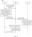
- FIG. 10 shows another downlink transmission method according to this application. The following describes the method 1000.
- the SMF Before the SMF sends, to the RAN, the estimated moment at which the downlink service packet arrives at the RAN, the SMF first needs to determine the estimated moment at which the downlink service packet arrives at the RAN. For a manner in which the SMF determines the estimated moment at which the downlink service packet arrives at the RAN, refer to the descriptions in step S601 in the method 600. Details are not described herein again.
- the RAN determines first time adjustment information based on the estimated moment at which the downlink service packet arrives at the RAN and configuration information of a radio resource.
- the RAN may determine a first delay based on the estimated moment at which the downlink service packet arrives at the RAN and the configuration information of the radio resource, where the first delay is duration between a moment that is expected by the RAN and at which the downlink service packet arrives at the RAN and the estimated moment at which the downlink service packet arrives at the RAN, the moment that is expected by the RAN and at which the downlink service packet arrives at the RAN is within a first scheduling window, and a next scheduling window adjacent to the first scheduling window is a downlink scheduling window. Then, the RAN determines the first time adjustment information based on the first delay.
- the RAN determines the first time adjustment information based on the first delay, where the first time adjustment information may be the first delay.
- the first time adjustment information may be a fifth moment determined based on the first delay and the estimated moment t RANya at which the downlink service packet arrives at the RAN, where the fifth moment is an expected moment at which a UPF sends the downlink service packet.
- Fifth moment t RANya +First delay+T UPF-RAN .
- the first time adjustment information may be a fifth moment determined based on the first delay and an estimated moment t UPFya at which the downlink service packet arrives at a UPF, where the fifth moment is an expected moment at which the UPF sends the downlink service packet.
- Fifth moment t UPFya +First delay.
- the RAN needs to obtain t UPFya from the SMF. Specifically, in step 51001, the SMF sends t UPFya to the RAN.
- the RAN determines, based on the estimated moment at which the downlink service packet arrives at the RAN and the configuration information of the radio resource, the estimated second downlink scheduling window for the RAN to schedule the downlink service packet, and determines the boundary of the third scheduling window based on the second downlink scheduling window.
- the SMF determines, based on the estimated moment at which the downlink service packet arrives at the RAN and the configuration information of the radio resource, the estimated second downlink scheduling window for the RAN to schedule the downlink service packet, and determines the boundary of the third scheduling window based on the second downlink scheduling window. Details are not described herein again.
- the RAN may determine the first time adjustment information. For example, the RAN may first determine a first delay based on the boundary of the third scheduling window, and then determine the first time adjustment information based on the first delay. For this, refer to the descriptions, in step S601, of that the SMF determines the first delay based on the boundary of the third scheduling window. For another example, the RAN may directly determine the first time adjustment information based on the boundary of the third scheduling window. For example, refer to FIG. 5 .
- the RAN may determine, based on the configuration information of the radio resource and t1, that the estimated second downlink scheduling window for the RAN to schedule the downlink service packet is the downlink scheduling window 2.
- an expected moment at which the downlink service packet arrives at the RAN is within the third scheduling window, where the third scheduling window is the scheduling window, namely, the downlink scheduling window 1, previous to the second downlink scheduling window.
- the first time adjustment information may be the first delay, the first time adjustment information may be a sum of duration T2 (namely, the first delay) between an upper boundary of the downlink scheduling window 1 and t1 and t UPFya , or the first time adjustment information may be a sum of t RANya , the first delay, and T UPF-RAN .
- T2 duration between an upper boundary of the downlink scheduling window 1 and t1 and t UPFya
- T UPF-RAN a sum of duration T2 (namely, the first delay) between an upper boundary of the downlink scheduling window 1 and t1 and t UPFya
- the first time adjustment information may be a sum of t RANya , the first delay, and T UPF-RAN .
- T UPFya the SMF may determine, based on the configuration information of the radio resource and t2, that the estimated second downlink scheduling window for the RAN to schedule the downlink service packet is the downlink scheduling window 3.
- an expected moment at which the downlink service packet arrives at the RAN is within the third scheduling window, where the third scheduling window is the scheduling window, namely, the uplink scheduling window 1, previous to the second downlink scheduling window.
- the first time adjustment information may be the first delay, the first time adjustment information may be a sum of [T3, T4] and t UPFya , or the first time adjustment information may be a sum of [T3, T4], t RANya , and T UPF-RAN , where T3 is duration between a lower boundary of the uplink scheduling window 1 and t2, and T4 is duration between an upper boundary of an uplink scheduling window 2 and t2.
- the SMF sends the first time adjustment information to the UPF, and the UPF determines, based on the first time adjustment information, a first moment at which the downlink service packet is sent, and sends the downlink service packet at the first moment.
- Steps S 1004 to S 1006 are the same as steps S602 to S604. For details, refer to the descriptions of S602 to S604. Details are not described herein again.
- the method may further include S 1007 and S 1008.
- S 1007 and S 1008 are the same as S605 and S606. For details, refer to the descriptions of S605 and S606. Details are not described herein again.
- FIG. 11 shows another downlink transmission method according to this application. The following describes the method 1100.
- S1101 An SMF sends, to a RAN, an estimated moment at which a downlink service packet arrives at the RAN. Accordingly, the RAN receives, from the SMF, the estimated moment at which the downlink service packet arrives at the RAN.
- the RAN may determine a first delay based on the estimated moment at which the downlink service packet arrives at the RAN and the configuration information of the radio resource, and then determine the second time adjustment information based on the first delay.
- the first delay For how to determine the first delay, refer to the foregoing descriptions in step S801. Details are not described herein again.
- the RAN may indicate to the SMF whether the first delay is an advance or retardation. For example, if the first delay is determined based on a boundary of a third scheduling window, the first delay is the retardation; or if the first delay is determined based on a boundary of a sixth scheduling window, the first delay is the advance.
- the RAN may alternatively provide both the first delay that is the advance and the first delay that is the retardation for the SMF to select.
- the RAN may provide an additional indication for the SMF only when the second time adjustment information is the retardation.
- the second time adjustment information is the advance.
- the RAN may alternatively provide both the second time adjustment information that is the advance and the second time adjustment information that is the retardation for the SMF to select.
- Steps S 1104 to S1107 are the same as steps S802 to S805. For details, refer to the foregoing descriptions of steps S802 to S805. Details are not described herein again.
- the method may further include S1108 and S1109.
- S 1108 and S 1109 are the same as S806 and S807.
- S806 and S807 Details are not described herein again.
- FIG. 12 shows another downlink transmission method according to this application. The following describes the method 1200.
- the UPF determines a first moment based on the first information.
- a moment (denoted as a third moment) at which the downlink service packet sent by the UPF at the first moment arrives at the RAN is within a first scheduling window of the RAN, and a next scheduling window adjacent to the first scheduling window is a downlink scheduling window.
- the UPF is to send the downlink service packet at the first moment, so that the downlink service packet may be scheduled in a fourth downlink scheduling window after arriving at the RAN, and the fourth downlink scheduling window is the next scheduling window adjacent to the first scheduling window.
- a method for determining, by the UPF, the first time adjustment information based on the first information is the same as the method for determining, by the SMF, the first delay based on the configuration information of the radio resource and the estimated moment at which the downlink service packet arrives at the RAN in S601. For details, refer to the descriptions in S601. Details are not described herein again.
- the UPF may buffer a downlink packet of a first service based on the first time adjustment information after receiving the downlink packet of the first service, where buffer duration is duration indicated by the first time adjustment information.
- the UPF may determine the sending moment of the downlink service packet based on the first information provided by the SMF, so that the moment at which the downlink service packet arrives at the RAN may be within the first scheduling window of the RAN, the downlink service packet may be scheduled in a second downlink scheduling window, and the second downlink scheduling window is the next scheduling window adjacent to the first scheduling window. This helps reduce a scheduling waiting delay of scheduling the downlink service by an access network element, and helps guarantee an end-to-end delay of the downlink service packet.
- the method may further include the following steps.
- the UPF sends second information to the SMF. Accordingly, the SMF receives the second information from the UPF.
- the second information is the first moment or a waiting or buffer delay of the downlink service on the UPF.
- the SMF determines the third moment based on the second information.
- the SMF sends the third moment to the RAN, where the third moment is used by the RAN to schedule a downlink service.
- the third moment may be a sum of a moment at which the downlink service packet arrives at the UPF, the second information, and a transmission delay from the UPF to the RAN.
- the second information is the first moment
- the third moment may be a sum of the first moment and a transmission delay from the UPF to the RAN.
- step S1206 and step S1207 are also applicable, and details are not described in this application.
- the downlink service may be a periodic service
- a moment at which the downlink service packet is sent or scheduled may be a start sending moment of the downlink service packet, and subsequently each network element periodically sends or schedules the downlink service packet based on the moment.
- the transceiver unit 2010 may be configured to send information to another apparatus or receive information from the another apparatus, for example, send or receive time adjustment information (for example, first time adjustment information).
- the processing unit 1200 may be configured to perform internal processing of the apparatus, for example, obtain a first delay.
- the communication apparatus 2000 corresponds to the session management network element (for example, the SMF) in the foregoing methods.
- the communication apparatus 2000 may be a session management network element or a chip configured in the session management network element, and may include a unit configured to perform an operation performed by the session management network element.
- the communication apparatus 2000 corresponds to the session management network element in the method 600 or 800.
- the transceiver unit 2010 is configured to send time adjustment information related to the first delay to a first network element, where the first network element is a user plane network element or an application network element, the time adjustment information is for determining a first moment at which the user plane network element sends the downlink service packet, or is used by an application server to determine a second moment at which the downlink service packet is sent, and a third moment at which the downlink service packet sent by the user plane network element at the first moment or sent by the application server at the second moment arrives at the access network element is within the first scheduling window.
- the processing unit 2020 is specifically configured to obtain configuration information of a radio resource of the access network element and the estimated moment at which the downlink service packet arrives at the access network element; and determine the first delay based on the configuration information of the radio resource and the estimated moment at which the downlink service packet arrives at the access network element.
- the processing unit 2020 is specifically configured to: determine, based on the configuration information of the radio resource and the estimated moment at which the downlink service packet arrives at the access network element, an estimated second downlink scheduling window for the access network element to schedule the downlink service packet; determine a boundary of a third scheduling window based on the configuration information of the radio resource and the second downlink scheduling window, where the third scheduling window is a scheduling window previous to the second downlink scheduling window; and determine the first delay based on the boundary of the third scheduling window.
- the configuration information of the radio resource includes a slot start moment, slot duration, an uplink-downlink slot configuration, and a scheduling processing delay of the access network element.
- the processing unit 2020 is specifically configured to obtain the estimated moment at which the downlink service packet arrives at the access network element.
- the transceiver unit 2010 is further configured to send the estimated moment at which the downlink service packet arrives at the access network element to the access network element; and receive the first delay from the access network element.
- the processing unit 2020 is specifically configured to: determine, based on a transmission delay from the user plane network element to the access network element and an estimated moment at which the downlink service packet arrives at the user plane network element, the estimated moment at which the downlink service packet arrives at the access network element; or obtain quality of service QoS information of the downlink service from a policy control network element, and determine, based on the QoS information, the estimated moment at which the downlink service packet arrives at the access network element.
- the time adjustment information is the first delay or a fourth moment determined based on the first delay and the estimated moment at which the downlink service packet arrives at the user plane network element.
- the time adjustment information includes one or more of the following: the first delay, an expected moment that is determined based on the first delay and at which the downlink service packet arrives at the user plane network element, and an expected moment that is determined based on the first delay and at which the downlink service packet arrives at a terminal device.
- the processing unit 2020 is further configured to determine the third moment based on the time adjustment information.
- the transceiver unit 2010 is further configured to send the third moment to the access network element, where the third moment is used by the access network element to schedule the downlink service packet.
- the communication apparatus 2000 corresponds to the session management network element in the method 1200.
- the transceiver unit 2010 is further configured to receive second information from the user plane network element, where the second information is the first moment or a waiting delay of the downlink service packet on the user plane network element.
- the processing unit 2020 is further configured to determine the third moment based on the second information.
- the transceiver unit 2010 is further configured to send the third moment to the access network element.
- the communication apparatus 2000 may further correspond to the session management network element in the methods 1000 and 1100.
- the communication apparatus 2000 For specific operations performed by the communication apparatus 2000, refer to the descriptions of the session management network element in the methods 1000 and 1100. Details are not described herein again.
- the communication apparatus 2000 corresponds to the user plane network element (for example, the UPF) in the foregoing methods.
- the communication apparatus 2000 may be a user plane network element or a chip configured in the user plane network element, and may include a unit configured to perform an operation performed by the user plane network element.
- the communication apparatus 2000 corresponds to the user plane network element in the method 1200.
- the transceiver unit 2010 is configured to receive first information from a session management network element, where the first information includes configuration information of a radio resource and an estimated moment at which a downlink service packet arrives at an access network element.
- the processing unit 2020 is configured to determine, based on the first information, a first moment at which the downlink service packet is sent, where a third moment at which the downlink service packet sent at the first moment arrives at the access network element is within a first scheduling window of the access network element, and a next scheduling window adjacent to the first scheduling window is a downlink scheduling window.
- the processing unit 2020 is specifically configured to: determine a first delay based on the first information, where the first delay is duration between an expected moment at which the downlink service packet arrives at the access network element and the estimated moment at which the downlink service packet arrives at the access network element; and determine the first moment based on the first delay.
- the transceiver unit 2010 is further configured to send second information to the session management network element, where the second information is the first moment or a waiting delay of the downlink service on the communication apparatus 2000, and the second information is for determining the third moment.
- the communication apparatus 2000 may further correspond to the user plane network element in the methods 1000 and 1100.
- the communication apparatus 2000 For specific operations performed by the communication apparatus 2000, refer to the description of the user plane network element in the methods 1000 and 1100. Details are not described herein again.
- the communication apparatus 2000 corresponds to the application network element (for example, the AF) in the foregoing methods.
- the communication apparatus 2000 may be an application network element or a chip configured in the application network element, and may include a unit configured to perform an operation performed by the application network element.
- the communication apparatus 2000 corresponds to the application network element in the method 800.
- the transceiver unit 2010 is configured to receive, from a session management network element, time adjustment information related to a first delay, where the first delay is duration between an expected moment at which a downlink service packet arrives at an access network element and an estimated moment at which the downlink service packet arrives at the access network element, the expected moment at which the downlink service packet arrives at the access network element is within a first scheduling window, and a next scheduling window adjacent to the first scheduling window is a downlink scheduling window.
- the processing unit 2020 is configured to determine, based on the time adjustment information, a second moment at which an application server sends the downlink service packet, where a third moment at which the downlink service packet sent at the second moment arrives at the access network element is within the first scheduling window.
- the time adjustment information includes one or more of the following: the first delay, an expected moment that is determined based on the first delay and at which the downlink service packet arrives at a user plane network element, and an expected moment that is determined based on the first delay and at which the downlink service packet arrives at a terminal device.
- the communication apparatus 2000 may further correspond to the application network element in the method 1100.
- the communication apparatus 2000 For specific operations performed by the communication apparatus 2000, refer to the descriptions of the application network element in the method 1100. Details are not described herein again.
- the communication apparatus 2000 corresponds to the access network element (for example, the RAN) in the foregoing methods.
- the communication apparatus 2000 may be an access network element or a chip configured in the access network element, and may include a unit configured to perform an operation performed by the access network element.
- the communication apparatus 2000 corresponds to the access network element in the method 600 or 800.
- the transceiver unit 2010 is configured to receive, from a session management network element, an estimated moment at which a downlink service packet arrives at the communication apparatus 2000.
- the processing unit 2020 is configured to determine a first delay based on the estimated moment at which the downlink service packet arrives at the communication apparatus 2000, where the first delay is duration between an moment that is expected by the communication apparatus 2000 and at which the downlink service packet arrives at the communication apparatus 2000 and the estimated moment at which the downlink service packet arrives at the communication apparatus 2000, the moment that is expected by the communication apparatus 2000 and at which the downlink service packet arrives at the communication apparatus 2000 is within a first scheduling window, and a next scheduling window adjacent to the first scheduling window is a downlink scheduling window.
- the transceiver unit 2010 is further configured to send the first delay to the session management network element, where the first delay is used by the session management network element to adjust a moment at which a user plane network element sends the downlink service packet and/or a moment at which an application server sends the downlink service packet.
- the processing unit 2020 is specifically configured to determine the first delay based on the estimated moment at which the downlink service packet arrives at the communication apparatus 2000 and configuration information of a radio resource of the communication apparatus 2000.
- the configuration information of the radio resource includes a slot start moment, slot duration, an uplink-downlink slot configuration, and a scheduling processing delay of the communication apparatus 2000.
- FIG. 14 is a schematic block diagram of another communication apparatus 3000 according to this application.
- Any network element for example, the session management network element, the application network element, the user plane network element, or the access network element, in the foregoing method embodiments, may be implemented by the communication apparatus shown in FIG. 14 .
- the communication apparatus 3000 includes one or more processors 3100.
- the processor 3100 may store execution instructions for performing the method in embodiments of this application.
- the processor 3100 may invoke a communication interface 3200 to implement receiving and sending functions.
- the communication interface 3200 may be a logical interface or a physical interface. This is not limited.
- the communication interface 3200 may be a transceiver circuit, an interface circuit, a transceiver, or a transceiver circuit configured to implement the receiving and sending functions.
- the sending function and the receiving function of the communication interface 3200 may be separated, or may be integrated.
- the transceiver circuit or the interface circuit may be configured to read and write code/data, or the transceiver circuit or the interface circuit may be configured to transmit or transfer a signal.
- the communication apparatus 3000 may further include a memory 3300.
- a specific deployment location of the memory 3300 is not specifically limited in this embodiment of this application.
- the memory 3300 may be integrated into the processor 3100, or may be independent of the processor 3100.
- the communication apparatus 3000 does not include a memory, the communication apparatus 3000 only needs to have a processing function, and the memory may be deployed at another location (for example, a cloud system).
- the memory 3300 may store the execution instructions for performing the method in embodiments of this application.
- the processor 3100 may execute the instructions stored in the memory 3300 and complete, in combination with other hardware (for example, the communication interface 3200), steps performed in the following method.
- other hardware for example, the communication interface 3200
- the method disclosed in embodiments of this application may be applied to the memory 3300, or may be implemented by the memory 3300.
- the memory 3300 may be an integrated circuit chip with a signal processing capability.
- the steps of the method may be performed through a hardware integrated logic circuit in the processor or by using instructions in a form of software.
- the foregoing processor may be a general-purpose processor, a digital signal processor (digital signal processor, DSP), an application specific integrated circuit (application specific integrated circuit, ASIC), a field programmable gate array (field programmable gate array, FPGA) or another programmable logic device, a discrete gate or a transistor logic device, or a discrete hardware component.
- RAMs are available, for example, a static random access memory (static RAM, SRAM), a dynamic random access memory (dynamic RAM, DRAM), a synchronous dynamic random access memory (synchronous DRAM, SDRAM), a double data rate synchronous dynamic random access memory (double data rate SDRAM, DDR SDRAM), an enhanced synchronous dynamic random access memory (enhanced SDRAM, ESDRAM), a synchlink dynamic random access memory (synchlink DRAM, SLDRAM), and a direct rambus random access memory (direct rambus RAM, DR RAM).
- static random access memory static random access memory
- DRAM dynamic random access memory
- DRAM dynamic random access memory
- SDRAM synchronous dynamic random access memory
- double data rate SDRAM double data rate SDRAM
- DDR SDRAM double data rate SDRAM
- ESDRAM enhanced synchronous dynamic random access memory
- synchlink dynamic random access memory synchlink dynamic random access memory
- direct rambus RAM direct rambus RAM
- FIG. 15 is a schematic diagram of a structure of a network device according to an embodiment of this application.
- FIG. 15 may be a schematic diagram of a structure of a base station.
- the network device 4000 may be used in the system shown in FIG. 1 or FIG. 2 , and perform a function of the access network element in the foregoing method embodiments.
- the network device 4000 may include one or more radio frequency units such as remote radio units (remote radio units, RRUs) 4100 and one or more baseband units (BBUs) (which may also be referred to as distributed units (DUs)) 4200.
- RRUs remote radio units
- BBUs baseband units
- DUs distributed units
- the RRU 4100 may be referred to as a transceiver unit or a communication unit, and corresponds to the transceiver unit 2010 in FIG. 13 .
- the transceiver unit 4100 may also be referred to as a transceiver, a transceiver circuit, or the like, and may include at least one antenna 4101 and a radio frequency unit 4102.
- the transceiver unit 4100 may include a receiving unit and a sending unit.
- the receiving unit may correspond to a receiver (or referred to as a receiver circuit), and the sending unit may correspond to a transmitter (or referred to as a transmitter circuit).
- the RRU 4100 is mainly configured to send and receive radio frequency signals and perform conversion between a radio frequency signal and a baseband signal.
- the BBU 4200 is mainly configured to perform baseband processing, control the network device, and so on.
- the RRU 4100 and the BBU 4200 may be physically disposed together, or may be physically disposed separately, namely, a distributed base
- the BBU 4200 is a control center of the network device, may also be referred to as a processing unit, may correspond to the processing unit 2020 in FIG. 13 , and is mainly configured to implement a baseband processing function, for example, channel coding, multiplexing, modulation, or spreading.
- the BBU (the processing unit) may be configured to control the network device to perform operation procedures related to the access network device in the foregoing method embodiments.
- the BBU 4200 may include one or more boards, and a plurality of boards may jointly support a radio access network (for example, an LTE network) having a single access standard, or may separately support radio access networks (for example, the LTE network, a 5G network, or another network) having different access standards.
- the BBU 4200 further includes a memory 4201 and a processor 4202.
- the memory 4201 is configured to store necessary instructions and data.
- the processor 4202 is configured to control the network device to perform a necessary action, for example, is configured to control the network device to perform the operation procedures related to the access network device in the foregoing method embodiments.
- the memory 4201 and the processor 4202 may serve one or more boards. In other words, the memory and the processor may be separately disposed on each board. Alternatively, a plurality of boards may share a same memory and a same processor. In addition, a necessary circuit may further be disposed on each board.
- the BBU 4200 may be configured to perform an action implemented inside the access network device in the foregoing method embodiments, and the RRU 4100 may be configured to perform an action of sending by the access network device to the terminal device or receiving from the terminal device in the foregoing method embodiments.
- the RRU 4100 may be configured to perform an action of sending by the access network device to the terminal device or receiving from the terminal device in the foregoing method embodiments.
- the computer program product includes computer program code.
- the computer program code When the computer program code is run on a computer, the computer is enabled to perform the method on the session management network element side, the application network element side, the user plane network element side, or the access network element side in any one of the foregoing method embodiments.
- This application further provides a system, including one or more of the foregoing session management network element, application network element, user plane network element, and access network element.
- the system may further include the foregoing terminal device.
- an embodiment of this application further provides a processing apparatus, including a processor and an interface.
- the processor is configured to perform the communication method in any one of the foregoing method embodiments.
- the processing apparatus may be a chip.
- the processing apparatus may be a field programmable gate array (field programmable gate array, FPGA), may be a general-purpose processor, a digital signal processor (digital signal processor, DSP), an application specific integrated circuit (application specific integrated circuit, ASIC), the field programmable gate array (field programmable gate array, FPGA), another programmable logic device, a discrete gate, a transistor logic device, or a discrete hardware component, may be a system on chip (system on chip, SoC), may be a central processing unit (central processing unit, CPU), may be a network processor (network processor, NP), may be a digital signal processor (digital signal processor, DSP), may be a micro controller unit (micro controller unit, MCU), or may be a programmable logic device (programmable logic device, P
- the processing apparatus may implement or perform the methods, the steps, and logical block diagrams that are disclosed in embodiments of this application.
- the general-purpose processor may be a microprocessor, or the processor may be any conventional processor or the like. Steps of the methods disclosed with reference to embodiments of this application may be directly executed and accomplished by using a hardware decoding processor, or may be executed and accomplished by using a combination of hardware in a decoding processor and a software module.
- the software module may be located in a mature storage medium in the art, such as a random access memory, a flash memory, a read-only memory, a programmable read-only memory, an electrically erasable programmable memory, or a register. The storage medium is located in the memory, and the processor reads information in the memory, and completes the steps in the foregoing methods in combination with hardware of the processor.
- the memory in this embodiment of this application may be a volatile memory or a nonvolatile memory, or may include a volatile memory and a nonvolatile memory.
- the nonvolatile memory may be a read-only memory (read-only memory, ROM), a programmable read-only memory (programmable ROM, PROM), an erasable programmable read-only memory (erasable PROM, EPROM), an electrically erasable programmable read-only memory (electrically EPROM, EEPROM), or a flash memory.
- the volatile memory may be a random access memory (random access memory, RAM) that is used as an external cache.
- All or some of the foregoing embodiments may be implemented by using software, hardware, firmware, or any combination thereof.
- software is for implementing embodiments, all or some of embodiments may be implemented in a form of a computer program product.
- the computer program product includes one or more computer instructions. When the computer instructions are loaded and executed on the computer, the procedure or functions according to embodiments of this application are all or partially generated.
- the computer may be a general-purpose computer, a dedicated computer, a computer network, or other programmable apparatuses.
- the computer instructions may be stored in a computer-readable storage medium or may be transmitted from a computer-readable storage medium to another computer-readable storage medium.
- the computer instructions may be transmitted from a website, computer, server, or data center to another website, computer, server, or data center in a wired (for example, a coaxial cable, an optical fiber, or a digital subscriber line (digital subscriber line, DSL)) or wireless (for example, infrared, radio, or microwave) manner.
- the computer-readable storage medium may be any usable medium accessible by the computer, or a data storage device, for example, a server or a data center, integrating one or more usable media.
- the usable medium may be a magnetic medium (for example, a floppy disk, a hard disk drive, or a magnetic tape), an optical medium (for example, a digital video disc (digital video disc, DVD)), a semiconductor medium (for example, a solid state disc (solid state disc, SSD)), or the like.
- a magnetic medium for example, a floppy disk, a hard disk drive, or a magnetic tape
- an optical medium for example, a digital video disc (digital video disc, DVD)
- a semiconductor medium for example, a solid state disc (solid state disc, SSD)
- the network device and the terminal device in the foregoing apparatus embodiments exactly correspond to the network device and the terminal device in the method embodiments.
- a corresponding module or unit performs a corresponding step.
- a communication unit (a transceiver) performs a receiving step or a sending step in the method embodiments
- a processing unit may perform a step other than the sending step and the receiving step.
- a function of a specific unit refer to a corresponding method embodiment.
- ком ⁇ онент may be but is not limited to a process that runs on a processor, a processor, an object, an executable file, an execution thread, a program, or a computer.
- a computing device and an application that runs on the computing device may be components.
- One or more components may reside within a process or an execution thread, and a component may be located on one computer or distributed between two or more computers.
- these components may be executed by various computer-readable media that store various data structures.
- the components may communicate by using a local or remote process based on a signal having one or more data packets (for example, data from two components interacting with another component in a local system, in a distributed system, or across a network such as the Internet interacting with another system by using the signal).
- a signal having one or more data packets (for example, data from two components interacting with another component in a local system, in a distributed system, or across a network such as the Internet interacting with another system by using the signal).
- an "embodiment” mentioned throughout this specification means that particular features, structures, or characteristics related to this embodiment are included in at least one embodiment of this application. Therefore, embodiments in the entire specification do not necessarily refer to a same embodiment. In addition, these particular features, structures, or characteristics may be combined in one or more embodiments in any proper manner. It should be understood that, in embodiments of this application, numbers “first”, “second”, and the like are merely for distinguishing between different objects, for example, to distinguish between different network devices, and do not constitute a limitation on the scope of embodiments of this application. Embodiments of this application are not limited thereto.
- the terminal device and/or the network device may perform some or all steps in embodiments of this application. These steps or operations are merely examples. In embodiments of this application, other operations or variations of various operations may be further performed. In addition, the steps may be performed in a sequence different from a sequence presented in embodiments of this application, and not all the operations in embodiments of this application may be performed.
Landscapes
- Engineering & Computer Science (AREA)
- Computer Networks & Wireless Communication (AREA)
- Signal Processing (AREA)
- Quality & Reliability (AREA)
- Mobile Radio Communication Systems (AREA)
- Data Exchanges In Wide-Area Networks (AREA)
Applications Claiming Priority (2)
| Application Number | Priority Date | Filing Date | Title |
|---|---|---|---|
| CN202010877423.7A CN114126050B (zh) | 2020-08-27 | 2020-08-27 | 下行传输的方法和通信装置 |
| PCT/CN2021/105986 WO2022042095A1 (zh) | 2020-08-27 | 2021-07-13 | 下行传输的方法和通信装置 |
Publications (2)
| Publication Number | Publication Date |
|---|---|
| EP4199620A1 true EP4199620A1 (de) | 2023-06-21 |
| EP4199620A4 EP4199620A4 (de) | 2024-02-28 |
Family
ID=80354504
Family Applications (1)
| Application Number | Title | Priority Date | Filing Date |
|---|---|---|---|
| EP21859935.5A Pending EP4199620A4 (de) | 2020-08-27 | 2021-07-13 | Downlink-übertragungsverfahren und kommunikationsvorrichtung |
Country Status (7)
| Country | Link |
|---|---|
| US (2) | US12538309B2 (de) |
| EP (1) | EP4199620A4 (de) |
| JP (1) | JP7675177B2 (de) |
| CN (1) | CN114126050B (de) |
| BR (1) | BR112023003594A2 (de) |
| CA (1) | CA3191120A1 (de) |
| WO (1) | WO2022042095A1 (de) |
Families Citing this family (3)
| Publication number | Priority date | Publication date | Assignee | Title |
|---|---|---|---|---|
| CN120570006A (zh) * | 2023-01-26 | 2025-08-29 | 索尼集团公司 | 基站、通信系统和通信方法 |
| CN116405049B (zh) * | 2023-03-06 | 2026-04-03 | 新华三技术有限公司 | 移动通信报文收发系统及方法 |
| CN118199782B (zh) * | 2024-05-20 | 2024-07-23 | 南昌智能新能源汽车研究院 | 以太网报文分时调度方法、系统、存储介质及智能设备 |
Family Cites Families (29)
| Publication number | Priority date | Publication date | Assignee | Title |
|---|---|---|---|---|
| US6690683B1 (en) * | 1999-11-23 | 2004-02-10 | International Business Machines Corporation | Method and apparatus for demultiplexing a shared data channel into a multitude of separate data streams, restoring the original CBR |
| US7126945B2 (en) * | 2001-11-07 | 2006-10-24 | Symbol Technologies, Inc. | Power saving function for wireless LANS: methods, system and program products |
| KR100933159B1 (ko) * | 2003-07-11 | 2009-12-21 | 삼성전자주식회사 | 이동통신시스템에서 음성 데이터 전송을 위한 동기화 방법 및 시스템 |
| US8363681B2 (en) * | 2008-10-16 | 2013-01-29 | Entropic Communications, Inc. | Method and apparatus for using ranging measurements in a multimedia home network |
| WO2010112975A2 (en) * | 2009-03-31 | 2010-10-07 | Freescale Semiconductor, Inc. | Receiving node in a packet communications system and method for managing a buffer in a receiving node in a packet communications system |
| US8699411B1 (en) * | 2009-09-30 | 2014-04-15 | Google Inc. | Dynamic TDMA system for TV white space MIMO wireless |
| KR20120055947A (ko) * | 2010-11-24 | 2012-06-01 | 한국전자통신연구원 | 가입자 인지 플로우별 QoS 제공 방법 및 장치 |
| WO2012154152A1 (en) * | 2011-05-06 | 2012-11-15 | Google Inc. | Apparatus and method for rendering video with retransmission delay |
| US9787416B2 (en) * | 2012-09-07 | 2017-10-10 | Apple Inc. | Adaptive jitter buffer management for networks with varying conditions |
| US9998991B2 (en) * | 2013-08-28 | 2018-06-12 | Telefonaktiebolaget L M Ericsson (Publ) | Method and apparatuses for discontinuous reception cycle estimation by data packet monitoring |
| US20160127066A1 (en) * | 2014-11-03 | 2016-05-05 | Qualcomm Incorporated | Relative clock drift calibration for channel stitching |
| US10555297B2 (en) | 2016-03-31 | 2020-02-04 | Telefonaktiebolaget Lm Ericsson (Publ) | Uplink transmission timing control |
| CN107889217B (zh) * | 2016-09-29 | 2024-02-27 | 中兴通讯股份有限公司 | 业务会话发送、接收方法、装置及系统 |
| CN108282198B (zh) * | 2017-01-06 | 2021-11-19 | 华为技术有限公司 | 一种信号传输方法和装置 |
| US10375665B2 (en) * | 2017-02-06 | 2019-08-06 | Huawei Technologies Co., Ltd. | Method and apparatus for supporting access control and mobility management |
| US10454811B2 (en) * | 2017-04-07 | 2019-10-22 | Qualcomm Incorporated | Apparatus and method for de-jitter buffer delay adjustment |
| JP6848769B2 (ja) * | 2017-08-29 | 2021-03-24 | トヨタ自動車株式会社 | 車載中継装置、情報処理システム、中継装置、情報処理方法、及びプログラム |
| CN111373792A (zh) * | 2017-11-19 | 2020-07-03 | Lg电子株式会社 | 无线通信系统中的切换方法及其设备 |
| CN110366258B (zh) * | 2018-04-09 | 2021-08-31 | 华为技术有限公司 | 一种数据传输的方法、相关设备及通信系统 |
| US11252613B2 (en) * | 2018-04-17 | 2022-02-15 | Telefonaktiebolaget Lm Ericsson (Publ) | Dynamic bearer validity |
| US20200092739A1 (en) * | 2018-09-18 | 2020-03-19 | Qualcomm Incorporated | Methods and apparatuses for a user equipment (ue) based channel state information (csi) reporting request |
| KR102748588B1 (ko) * | 2018-09-21 | 2025-01-02 | 텔레호낙티에볼라게트 엘엠 에릭슨(피유비엘) | 무선 액세스 네트워크들에서 리소스들을 스케줄링하기 위한 방법들 및 장치들 |
| CN111200848B (zh) * | 2018-11-19 | 2022-03-25 | 华为技术有限公司 | 一种通信方法及装置 |
| US11930392B2 (en) * | 2018-11-20 | 2024-03-12 | Nokia Technologies Oy | Latency-bounded packet delivery in mobile communication system |
| CN111277993B (zh) * | 2019-01-11 | 2021-11-26 | 维沃移动通信有限公司 | 支持时间敏感通信的方法、通信设备及介质 |
| US11349764B2 (en) * | 2019-02-15 | 2022-05-31 | Qualcomm Incorporated | Methods and apparatus for signaling offset in a wireless communication system |
| WO2020174917A1 (ja) * | 2019-02-26 | 2020-09-03 | 日本電気株式会社 | 通信制御装置、通信制御方法、及び非一時的なコンピュータ可読媒体 |
| US10735120B1 (en) * | 2019-03-20 | 2020-08-04 | Qualcomm Incorporated | Reducing end-to-end delay for audio communication |
| CN110213007B (zh) * | 2019-06-24 | 2021-08-03 | 腾讯科技(深圳)有限公司 | 一种时钟漂移处理的方法、网络功能网元及存储介质 |
-
2020
- 2020-08-27 CN CN202010877423.7A patent/CN114126050B/zh active Active
-
2021
- 2021-07-13 JP JP2023513841A patent/JP7675177B2/ja active Active
- 2021-07-13 WO PCT/CN2021/105986 patent/WO2022042095A1/zh not_active Ceased
- 2021-07-13 BR BR112023003594A patent/BR112023003594A2/pt unknown
- 2021-07-13 EP EP21859935.5A patent/EP4199620A4/de active Pending
- 2021-07-13 CA CA3191120A patent/CA3191120A1/en active Pending
-
2023
- 2023-02-24 US US18/174,245 patent/US12538309B2/en active Active
-
2025
- 2025-09-15 US US19/328,612 patent/US20260012946A1/en active Pending
Also Published As
| Publication number | Publication date |
|---|---|
| BR112023003594A2 (pt) | 2023-04-04 |
| KR20230057454A (ko) | 2023-04-28 |
| JP2023539320A (ja) | 2023-09-13 |
| WO2022042095A1 (zh) | 2022-03-03 |
| CN114126050A (zh) | 2022-03-01 |
| US12538309B2 (en) | 2026-01-27 |
| CA3191120A1 (en) | 2022-03-03 |
| US20230254859A1 (en) | 2023-08-10 |
| US20260012946A1 (en) | 2026-01-08 |
| EP4199620A4 (de) | 2024-02-28 |
| CN114126050B (zh) | 2025-02-21 |
| JP7675177B2 (ja) | 2025-05-12 |
Similar Documents
| Publication | Publication Date | Title |
|---|---|---|
| EP4013108B1 (de) | Verfahren und gerät zur meldung von benutzerebeneninformationen | |
| US12538309B2 (en) | Downlink transmission method and communication apparatus | |
| KR102768952B1 (ko) | V2x 트래픽을 지원하기 위한 제어 채널 구조 설계 | |
| EP3925096A1 (de) | 5g-systemträger für virtuelle tsn-brückenverwaltung, qos-mapping und tsn-qbv-planung | |
| US11824783B2 (en) | Maximum data burst volume (MDBV) determining method, apparatus, and system | |
| WO2019228214A1 (zh) | 一种无线承载建立、业务流的监测方法及装置 | |
| US12040979B2 (en) | Communications method, apparatus, and system | |
| WO2021218321A1 (zh) | 用于处理数据流的方法和通信装置 | |
| US20240080716A1 (en) | Wireless communication method, communication apparatus, and communication system | |
| WO2021036910A1 (zh) | 数据传输方法及装置 | |
| CN115623542A (zh) | 通信方法、装置和系统 | |
| CN113261222A (zh) | 用于超可靠低延时通信的所协调的资源预留 | |
| CN111132223A (zh) | 一种数据包的传输方法和通信设备 | |
| US20250113363A1 (en) | Skipping transmission of uplink control information | |
| JP2026502239A (ja) | 通信方法、通信装置、及び通信システム | |
| KR102958074B1 (ko) | 다운링크 송신 방법 및 통신 장치 | |
| US20250280329A1 (en) | Communication method, apparatus, and system | |
| WO2024199073A1 (zh) | 通信方法和通信装置 | |
| WO2026012092A1 (zh) | 空口配置方法及相关装置 | |
| WO2025092284A1 (zh) | 数据传输方法和装置 | |
| WO2025246716A1 (zh) | 通信方法及相关装置 | |
| WO2025247179A1 (zh) | 一种通信方法、装置和可读存储介质 | |
| WO2024230307A1 (zh) | 通信方法及相关装置 | |
| WO2026026401A1 (zh) | 一种通信方法及相关装置 | |
| WO2025246839A1 (zh) | 通信方法、通信系统、设备及存储介质 |
Legal Events
| Date | Code | Title | Description |
|---|---|---|---|
| STAA | Information on the status of an ep patent application or granted ep patent |
Free format text: STATUS: THE INTERNATIONAL PUBLICATION HAS BEEN MADE |
|
| PUAI | Public reference made under article 153(3) epc to a published international application that has entered the european phase |
Free format text: ORIGINAL CODE: 0009012 |
|
| STAA | Information on the status of an ep patent application or granted ep patent |
Free format text: STATUS: REQUEST FOR EXAMINATION WAS MADE |
|
| 17P | Request for examination filed |
Effective date: 20230313 |
|
| AK | Designated contracting states |
Kind code of ref document: A1 Designated state(s): AL AT BE BG CH CY CZ DE DK EE ES FI FR GB GR HR HU IE IS IT LI LT LU LV MC MK MT NL NO PL PT RO RS SE SI SK SM TR |
|
| DAV | Request for validation of the european patent (deleted) | ||
| DAX | Request for extension of the european patent (deleted) | ||
| REG | Reference to a national code |
Ref country code: DE Ref legal event code: R079 Free format text: PREVIOUS MAIN CLASS: H04W0072040000 Ipc: H04L0047283000 |
|
| A4 | Supplementary search report drawn up and despatched |
Effective date: 20240130 |
|
| RIC1 | Information provided on ipc code assigned before grant |
Ipc: H04L 47/34 20220101ALN20240124BHEP Ipc: H04L 47/56 20220101ALI20240124BHEP Ipc: H04L 47/283 20220101AFI20240124BHEP |