EP4199637A1 - Procédé et appareil de reconfiguration à liaisons multiples - Google Patents
Procédé et appareil de reconfiguration à liaisons multiples Download PDFInfo
- Publication number
- EP4199637A1 EP4199637A1 EP22739062.2A EP22739062A EP4199637A1 EP 4199637 A1 EP4199637 A1 EP 4199637A1 EP 22739062 A EP22739062 A EP 22739062A EP 4199637 A1 EP4199637 A1 EP 4199637A1
- Authority
- EP
- European Patent Office
- Prior art keywords
- mld
- link
- frame
- field
- indicates
- Prior art date
- Legal status (The legal status is an assumption and is not a legal conclusion. Google has not performed a legal analysis and makes no representation as to the accuracy of the status listed.)
- Granted
Links
Images


Classifications
-
- H—ELECTRICITY
- H04—ELECTRIC COMMUNICATION TECHNIQUE
- H04W—WIRELESS COMMUNICATION NETWORKS
- H04W76/00—Connection management
- H04W76/10—Connection setup
- H04W76/15—Setup of multiple wireless link connections
-
- H—ELECTRICITY
- H04—ELECTRIC COMMUNICATION TECHNIQUE
- H04W—WIRELESS COMMUNICATION NETWORKS
- H04W76/00—Connection management
- H04W76/10—Connection setup
- H04W76/19—Connection re-establishment
-
- H—ELECTRICITY
- H04—ELECTRIC COMMUNICATION TECHNIQUE
- H04W—WIRELESS COMMUNICATION NETWORKS
- H04W76/00—Connection management
- H04W76/20—Manipulation of established connections
-
- H—ELECTRICITY
- H04—ELECTRIC COMMUNICATION TECHNIQUE
- H04W—WIRELESS COMMUNICATION NETWORKS
- H04W76/00—Connection management
- H04W76/30—Connection release
-
- H—ELECTRICITY
- H04—ELECTRIC COMMUNICATION TECHNIQUE
- H04W—WIRELESS COMMUNICATION NETWORKS
- H04W76/00—Connection management
- H04W76/30—Connection release
- H04W76/34—Selective release of ongoing connections
-
- H—ELECTRICITY
- H04—ELECTRIC COMMUNICATION TECHNIQUE
- H04W—WIRELESS COMMUNICATION NETWORKS
- H04W84/00—Network topologies
- H04W84/02—Hierarchically pre-organised networks, e.g. paging networks, cellular networks, WLAN [Wireless Local Area Network] or WLL [Wireless Local Loop]
- H04W84/10—Small scale networks; Flat hierarchical networks
- H04W84/12—WLAN [Wireless Local Area Networks]
-
- Y—GENERAL TAGGING OF NEW TECHNOLOGICAL DEVELOPMENTS; GENERAL TAGGING OF CROSS-SECTIONAL TECHNOLOGIES SPANNING OVER SEVERAL SECTIONS OF THE IPC; TECHNICAL SUBJECTS COVERED BY FORMER USPC CROSS-REFERENCE ART COLLECTIONS [XRACs] AND DIGESTS
- Y02—TECHNOLOGIES OR APPLICATIONS FOR MITIGATION OR ADAPTATION AGAINST CLIMATE CHANGE
- Y02D—CLIMATE CHANGE MITIGATION TECHNOLOGIES IN INFORMATION AND COMMUNICATION TECHNOLOGIES [ICT], I.E. INFORMATION AND COMMUNICATION TECHNOLOGIES AIMING AT THE REDUCTION OF THEIR OWN ENERGY USE
- Y02D30/00—Reducing energy consumption in communication networks
- Y02D30/70—Reducing energy consumption in communication networks in wireless communication networks
Definitions
- one or more links may be established between two MLDs for communication through an association procedure.
- the links established between two MLDs may not satisfy requirements for data transmission between the two MLDs. There is no solution to solve this problem in the industry.
- the first MLD and the second MLD may continue to buffer the following information: an enhanced distributed channel access (enhanced distributed channel access, EDCA) function state, a block acknowledgment agreement, a sequence number (Sequence Number, SN), a packet number (packet number, PN), a duplicate detection cache, data queued for transmission, a fragment and reassembly buffer, a power management mode, and a wireless network management sleep mode.
- EDCA enhanced distributed channel access
- that the first frame is used to reconfigure a link between the first MLD and a second MLD includes: the first frame indicates to remove a target link from a link established between the first MLD and the second MLD. It should be understood that corresponding energy consumption may be reduced on the first MLD and the second MLD by removing one or more links between them.
- that the first frame is used to reconfigure a link between the first MLD and a second MLD includes: the first frame indicates a target link, and the target link is used for data transmission between the first MLD and the second MLD.
- the link transition may enable the two MLDs to switch from a link with poor quality to a link with better quality for data transmission, which helps improve quality of service of data transmission between the two MLDs.
- the method before the first MLD receives the request frame from the second MLD, the method further includes: the first MLD sends a query frame to the second MLD, where the query frame is used to negotiate link transition between the first MLD and the second MLD. Based on this design, the first MLD may send the query frame to trigger negotiation of link transition between the two MLDs.
- that the first frame is used to reconfigure a link between the first MLD and the second MLD includes: the first frame indicates to remove a target link from a link established between the first MLD and the second MLD.
- the first frame includes a first field
- the first field indicates a reconfiguration type
- the reconfiguration type includes link removal, link addition, or link transition.
- the first frame further includes a third field, the third field indicates whether the first link is the target link, and the first link is a link used to communicate the first frame.
- the first frame is a reassociation request frame or a disassociation frame; the first frame includes a multi-link element, the multi-link element includes a multi-link control field, and the multi-link control field includes a type field.
- the type field whose value is a first preset value indicates that the first frame is used to reconfigure the link between the first MLD and the second MLD, and the first preset value is not 0 or 1.
- the method before the second MLD sends the request frame to the first MLD, the method further includes: the second MLD receives a query frame from the first MLD, where the query frame is used to negotiate link transition between the first MLD and the second MLD.
- that the first frame is used to reconfigure a link between a first MLD and a second MLD includes: the first frame indicates to establish a target link between the first MLD and the second MLD.
- that the first frame is used to reconfigure a link between a first MLD and a second MLD includes: the first frame indicates to remove a target link from a link established between the first MLD and the second MLD.
- the second field includes a bitmap
- the bitmap includes at least one bit
- a bit in the bitmap indicates whether a link corresponding to the bit is the target link.
- the request frame further indicates a recommended link.
- that the first frame is used to reconfigure a link between the first MLD and a second MLD includes: the first frame indicates a target link, and the target link is used for data transmission between the first MLD and the second MLD.
- that the first frame is used to reconfigure a link between the first MLD and a second MLD includes: when the first field indicates link removal, the first frame indicates to remove a target link from a link established between the first MLD and the second MLD; when the first field indicates link addition, the first frame indicates to establish a target link between the first MLD and the second MLD; or when the first field indicates link transition, the first frame indicates to switch a link established between the first MLD and the second MLD to a target link.
- the first frame further includes a second field, and the second field indicates the target link.
- the second field includes a bitmap
- the bitmap includes at least one bit
- a bit in the bitmap indicates whether a link corresponding to the bit is the target link.
- a computer-readable storage medium stores instructions, and when the instructions run on a computer, the computer is enabled to perform the method in any design of the first aspect or the second aspect.
- a computer program product including instructions is provided.
- the computer program product runs on a computer, the computer is enabled to perform the method in any design of the first aspect or the second aspect.
- a chip including a processing circuit and a transceiver pin.
- the processing circuit is configured to perform a processing action in the corresponding method in the first aspect or the second aspect
- the transceiver pin is configured to perform a communication action in the corresponding method in the first aspect or the second aspect.
- any MLD, chip, computer storage medium, or computer program product provided above is configured to perform the corresponding method provided above. Therefore, for beneficial effects that can be achieved by the MLD, chip, computer storage medium, or computer program product, refer to beneficial effects in the corresponding method provided above. Details are not described herein again.
- the technical solutions provided in this application may be applied to various communication systems, for example, a system in which the IEEE 802.11 standard is applied.
- the IEEE 802.11 standard includes but is not limited to the 802.11be standard or a next-generation 802.11 standard.
- the technical solutions of this application are applicable to the following scenarios: communication between an AP and a STA, communication between APs, communication between STAs, and the like.
- the access point AP in this application is an apparatus that is deployed in a wireless communication network and that provides a wireless communication function for a STA associated with the access point AP.
- the access point AP may be used as a hub of the communication system, and may be a communication device such as a base station, a router, a gateway, a repeater, a communication server, a switch, or a bridge.
- the base station may include a macro base station, a micro base station, a relay station, and the like in various forms.
- the devices mentioned above are collectively referred to as access points APs.
- An IEEE 802.11 extremely high throughput (extremely high throughput, EHT) device that is, a next-generation Wireless Fidelity (wireless fidelity, Wi-Fi) device supports multiple streams, multiple frequency bands (for example, 2.4 GHz, 5 GHz, and 6 GHz frequency bands), collaboration of multiple channels on a same frequency band, and the like to improve peak throughput and reduce service transmission delay.
- EHT extremely high throughput
- the multiple frequency bands or the multiple channels may be collectively referred to as multiple links.
- a multi-link device includes one or more affiliated stations.
- the affiliated station may be a logical station or a physical station.
- "a multi-link device includes an affiliated station” may be briefly described as "a multi-link device includes a station”.
- the multi-link device may implement wireless communication in compliance with the 802.11 protocol.
- the 802.11 protocol may be the 802.11ax protocol, the 802.11be protocol, or a next-generation 802.11 protocol. This is not limited in embodiment of this application.
- the multi-link device may communicate with another device.
- the another device may be a multi-link device, or may not be a multi-link device.
- FIG. 1 is a schematic diagram of a scenario of communication between an AP multi-link device and STA multi-link devices.
- one AP multi-link device may be associated with a plurality of STA multi-link devices and single-link STAs.
- AP multi-link device 100 is associated with STA multi-link device 200, STA multi-link device 300, and STA 400.
- a plurality of APs in the AP multi-link device separately operate on multiple links
- a plurality of STAs in the STA multi-link device separately operate on multiple links
- a STA in the STA multi-link device is associated with an AP in the AP multi-link device on an operating link of the STA.
- a single-link STA is associated with an AP in the AP multi-link device on an operating link of the single-link STA.
- Frequency bands on which the multi-link device operates may include but are not limited to sub 1 GHz, 2.4 GHz, 5 GHz, 6 GHz, and high frequency 60 GHz.
- FIG. 2(a) and FIG. 2(b) show two schematic diagrams in which a multi-link device communicates with another device over multiple links in a wireless local area network.
- FIG. 2(a) shows a scenario in which AP multi-link device 101 communicates with STA multi-link device 102.
- AP multi-link device 101 includes affiliatedAP 101-1 and AP 101-2
- STA device multi-link 102 includes affiliated STA 102-1 and STA 102-2
- AP multi-link device 101 and STA multi-link device 102 communicate with each other over both link 1 and link 2.
- STA 104 operates in the 2.4 GHz frequency band
- STA multi-link device 103 includes STA 103-1 and STA 103-2, where STA 103-1 operates in the 5 GHz frequency band and STA 103-2 operates in the 6 GHz frequency band
- STA multi-link device 102 includes STA 102-1 and STA 102-2, where STA 102-1 operates in the 2.4 GHz frequency band and STA 102-2 operates in the 6 GHz frequency band.
- AP 101-1 operating in the 2.4 GHz frequency band in the AP multi-link device may exchange uplink or downlink data with STA 104 and STA 102-2 in the STA multi-link device 102 over link 1.
- AP 101-2 operating in the 5 GHz frequency band in the AP multi-link device may exchange uplink or downlink data with STA 103-1 operating in the 5 GHz frequency band in STA multi-link device 103 over link 2.
- AP 101-3 operating in the 6 GHz frequency band in AP multi-link device 101 may exchange uplink or downlink data with STA 102-2 operating in the 6 GHz frequency band in STA multi-link device 102 over link 3, and may also exchange uplink or downlink data with STA 103-2 in the STA multi-link device over link 3.
- the multi-link device is an apparatus having a wireless communication function.
- the apparatus may be an entire device, or may be a chip, a processing system, or the like installed in the entire device.
- the device on which the chip or the processing system is installed may be controlled by the chip or the processing system, to implement the methods and functions in embodiments of this application.
- the multi-link device may support simultaneous transmit and receive (simultaneous transmit and receive, STR) of data, or the multi-link device may not support simultaneous transmit and receive of data.
- Supporting simultaneous transmit and receive of data means that in a process in which the multi-link device sends data on one link, the multi-link device may receive data on another link.
- Not supporting simultaneous transmit and receive of data means that in a process in which the multi-link device sends data on one link, the multi-link device cannot receive data on another link.
- a non-AP MLD may perform a multi-link establishment operation on one of the links to simultaneously establish multiple links and establish association with the AP MLD.
- the non-AP MLD and the AP MLD may exchange multi-link association request/response (Multi-link Association Request/Response) frames on one link.
- the link on which the multi-link association request/response frames are exchanged may be referred to as a transmitted link (transmitted link), and other links are referred to as non-transmitted links (Non-transmitted Link).
- the multi-link association request/response may carry information about multiple links to be established, to simultaneously establish multiple links between the non-AP MLD and the AP MLD.
- a non-AP MLD sends a multi-link association request frame on link 1, and the multi-link association request frame carries STA-side information about link 1 and STA-side information about link 2.
- link 1 may be referred to as a transmitted link
- link 2 may be referred to as a non-transmitted link.
- the AP MLD sends a multi-link association response frame to the non-AP MLD on link 1, and the multi-link association response frame may carry AP-side information about link 1 and AP-side information about link 2. Therefore, link 1 and link 2 are established between the non-AP MLD and the AP MLD. Further, the non-AP MLD and the AP MLD may perform data transmission on link 1 and link 2.
- MLD-level info includes the following fields: multi-link control (Multi-link control) and one or more fields (fields).
- the one or more fields may include the following fields: element ID (element ID), length (length), extended element ID (element ID), and the like.
- the data field in the per-link profile includes one or more of the following fields: per-station control field (Per-STA control field), one or more elements, and a non-inheritance element (non-inheritance element).
- Per-STA control field per-station control field
- non-inheritance element non-inheritance element
- the non- inheritance element is an optional field.
- the per-station control field includes at least a link ID. It should be understood that the non-AP MLD may obtain link information (for example, a link ID) corresponding to each link by receiving a probe response frame or a beacon frame.
- link information for example, a link ID
- the established links may not satisfy requirement for data transmission between the two MLDs.
- multiple links are established when the two MLDs are initially associated.
- the data to be transmitted between the two MLDs is relatively small, and one link can meet throughput requirements of data transmission. Therefore, a redundant link needs to be removed between the two MLDs to reduce energy consumption.
- link 1 is established when the two MLDs are initially associated, but communication quality of link 1 is poor. Therefore, the two MLDs intend to transition from link 1 to link 2 for data transmission.
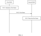
- An embodiment of this application provides a multi-link reconfiguration method to support link configuration change after two MLDs are associated. As shown in FIG. 4 , the method includes the following steps.
- a first MLD generates a first frame.
- the first frame is used to reconfigure multiple links between the first MLD and the second MLD.
- step S101 one or more links have been established between the first MLD and the second MLD through association.
- the first frame may be a newly defined frame, or reuse an existing frame (for example, a reassociation request frame or a disassociation frame). This is not limited.
- the first frame may use any one of the following designs.
- Design 1-1 The first frame indicates to establish a target link.
- link 1 and link 2 have been established between the first MLD and the second MLD through association.
- the first frame indicates to establish link 3, so that the link 3 may be further established between the first MLD and the second MLD.
- link 1, link 2, and link 3 may be used for data transmission between the first MLD and the second MLD.
- Design 1-2 The first frame indicates to remove a target link.
- the first frame indicates to remove the target link from a link established between the first MLD and the second MLD.
- the target link is a link currently established between the first MLD and the second MLD.
- link 1 and link 2 have been established between the first MLD and the second MLD through association.
- the first frame indicates to remove link 2.
- link 2 becomes an unestablished link between the first MLD and the second MLD.
- the first MLD and the second MLD can use only link 1 for data transmission, but cannot use link 2 for data transmission.
- Design 1-3 The first frame indicates a target link.
- the first frame indicates the target link for data transmission between the first MLD and the second MLD.
- link 1 and link 2 have been established between the first MLD and the second MLD through association.
- the first frame indicates link 2, link 3, and link 4, so that link 1 is removed and link 3 and link 4 are established between the first MLD and the second MLD.
- the first MLD and the second MLD may use link 2, link 3, and link 4 for data transmission, and cannot use link 1 for data transmission.
- the first frame indicates a link (that is, a target link) that should be finally established between the first MLD and the second MLD, so that the first MLD and the second MLD may determine a reconfiguration operation (for example, removing a link and/or adding a link) that should be actually performed based on a currently established link and the link that should be finally established.
- a link that is, a target link
- Case 1 When the first field indicates link removal, the first frame indicates to remove a target link.
- link 1 and link 2 have been established between the first MLD and the second MLD through association.
- the first field included in the first frame indicates link transition, and the first field indicates to switch from link 2 established between the first MLD and the second MLD to link 3. In this way, link 2 is removed and link 3 is established between the first MLD and the second MLD.
- the first MLD and the second MLD may exchange data on link 1 and link 3, but not on link 2.
- the first frame may include a multi-link element, the multi-link element includes a per-link profile, and the per-link profile includes a first field.
- the first frame may further include a second field, and the second field indicates the target link.
- the second field may use any one of the following designs.
- Design 2-1 The second field includes a link identifier of the target link.
- the second field includes a bitmap, the bitmap includes at least one bit, and one bit in the bitmap indicates whether a link corresponding to the bit is the target link.
- a value of a bit in the bitmap is 1, it indicates that a link corresponding to the bit is the target link; or if a value of a bit in the bitmap is 0, it indicates that a link corresponding to the bit is not the target link.
- a value of a bit in the bitmap is 0, it indicates that a link corresponding to the bit is the target link; or if a value of a bit in the bitmap is 1, it indicates that a link corresponding to the bit is not the target link.
- the first frame may include a multi-link element, the multi-link element includes a per-link profile, and the per-link profile includes a second field.
- the second field may have another name, for example, a target link set (target link set) field. This is not limited herein.
- the second field specifically indicates the target link in all links supported by the first MLD or all links supported by the second MLD.
- a quantity of bits in the bitmap may be the same as a quantity of links supported by the first MLD, so that the bits in the bitmap are in a one-to-one correspondence with the links supported by the first MLD.
- a quantity of bits in the bitmap may be the same as a quantity of links supported by the second MLD, so that the bits in the bitmap are in a one-to-one correspondence with the links supported by the second MLD.
- the second field specifically indicates the target link in one or more second links.
- the second links are other links in the links supported by the first MLD except the first link.
- the first link is a link used to communicate the first frame.
- a quantity of bits of the bitmap may be the same as a quantity of second links. Therefore, the bits in the bitmap are in a one-to-one correspondence with the second links.
- the second field does not indicate whether the first link is the target link.
- the first frame may explicitly indicate whether the first link is the target link.
- the first frame may further include a third field, and the third field indicates whether the first link is the target link.
- the third field may occupy one bit.
- the first frame may include a multi-link element, and MLD-level info in the multi-link element includes a third field.
- the first link may be considered as the target link by default.
- the first link may be considered as the target link by default.
- the first frame indicates the target link
- the first link may be considered as the target link by default.
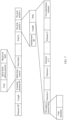
- Table 1 for a frame structure of the first frame.
- Table 1 shows only some information elements, and the first frame may further include another information element. This is not limited.
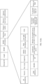
- Table 2 shows only some information elements, and the first frame may further include another information element. This is not limited.
- the first frame when the first frame reuses a reassociation request frame or a disassociation frame, the first frame may include a multi-link element.
- the first frame may be distinguished from an existing reassociation request frame or disassociation frame by using a type field in a multi-link control field in the multi-link element.
- the type field whose value is a first preset value indicates that the first frame is used to reconfigure a link between the first MLD and the second MLD.
- the first preset value is not 0 or 1.
- the first preset value may be 2.
- Table 3 Value of the type field Multi-link element variant name (variant name) 0 Basic (basic) 1 Probe request (probe request) 2 Multi-link reconfiguration (ML reconfiguration) TBD (to be determined, TBD) Reserved (reserved)
- a new multi-link element variant name is defined by using a reserved value (for example, 2) of the existing type field. Therefore, a device may determine that a frame using the multi-link element variant name is used for multi-link reconfiguration.
- the first frame reuses the reassociation request frame or the disassociation frame, which helps avoid excessive changes to the existing protocol.
- information that should be carried in the first frame does not need to be redefined, which further saves a reserved value of a category (category) field in the action frame.
- the first MLD sends the first frame to the second MLD to trigger link reconfiguration between the first MLD and the second MLD, so as to meet a requirement for communication between the two MLDs and ensure normal communication between the two MLDs.
- a peer device involved in reassociation of a device and a peer device involved in initial association of the device may not be a same device.
- device 1 is associated with device 2 in initial association and associated with device 3 in reassociation. Therefore, some information stored in the device is not applicable to communication with the peer device involved in reassociation. Therefore, according to the 802.11 protocol, during reassociation, the device deletes some information, such as enhanced distributed channel access (enhanced distributed channel access, EDCA) function status, block acknowledgment protocol, sequence number (sequence number, SN), packet number (packet number, PN), duplicate detection cache, data queued for transmission, fragment and reassembly buffer, power management mode, and wireless network management sleep mode. Then, the device renegotiates with the peer device involved in the reassociation to obtain the information.
- enhanced distributed channel access enhanced distributed channel access
- EDCA enhanced distributed channel access
- block acknowledgment protocol sequence number (sequence number, SN), packet number (packet number, PN
- the first MLD and the second MLD may not delete the foregoing information, so as to avoid operation overheads caused by subsequent negotiation to obtain the information.
- the first MLD and the second MLD may continue to buffer the following information: enhanced distributed channel access function status, block acknowledgment protocol, sequence number, packet number, duplicate detection cache, data queued for transmission, fragment and reassembly buffer, power management mode, wireless network management sleep mode, and the like.
- the second frame may be an acknowledgment (ACK) frame.
- ACK acknowledgment
- the second frame may reuse the reassociation response frame.
- the second frame may indicate whether to accept reconfiguration of the link between the first MLD and the second MLD.
- Table 4 For example, when the second frame reuses the reassociation response frame, refer to Table 4 for a frame structure of the second frame.
- the status code may indicate a response to a reconfiguration operation requested by the first frame.
- the second frame may include only one status code, and the status code is for all target links.
- the first frame may indicate to add link 1 and link 2, and the status code in the second frame indicates a success.
- link 1 and link 2 are established between the first MLD and the second MLD.
- the first frame may indicate to add link 1 and link 2, and the status code in the second frame indicates rejection. In this case, link 1 and link 2 are not established between the first MLD and the second MLD.
- the first frame may indicate to add link 1 and link 2, a status code corresponding to link 1 in the second frame indicates a success, and a status code corresponding to link 2 in the second frame indicate a failure.
- link 1 is established but link 2 is not established between the first MLD and the second MLD.
- the first frame may indicate to remove link 1 and link 2, a status code corresponding to link 1 in the second frame indicates a success, and a status code corresponding to link 2 in the second frame indicates a failure.
- link 1 is removed but link 2 is not removed between the first MLD and the second MLD.
- a status code corresponding to the target link may be located in a per-link profile corresponding to the target link.
- the second frame may include a multi-link element including a per-link profile, the per-link profile includes a per STA control field, and the per STA control field includes a status code.
- a status code corresponding to the target link may be a fixed field carried in a frame body, or may be located in MLD-level info in the multi-link element.
- the second frame may include a multi-link element, and the multi-link element may include a status code corresponding to the first link.
- the status code may be set to a reserved value or the status code corresponding to the first link is disregarded (disregard) in the second frame.
- the second MLD sends a second frame to the first MLD, to enable the first MLD to learn how to reconfigure the link between the first MLD and the second MLD.
- the STA and its affiliated AP may perform negotiation before BSS transition based on a BTM procedure, so that the STA may transition to a better BSS.
- the BTM procedure may include the following steps.
- the STA may send a basic service set transition management (BSS transition management, BTM) query (query) frame to its affiliated AP.
- BSS transition management, BTM basic service set transition management
- the step of sending the BTM query frame is optional.
- the AP may reply with an ACK frame.
- the AP may send a BTM request frame to the STA. After receiving the BTM request frame, the STA may reply with an ACK frame.
- the STA may send a BTM response frame to the AP, to indicate to accept or reject the BSS transition request.
- the AP may reply with an ACK frame.
- the BTM query frame may include the following fields: category (category), radio network management action (WNM action), dialog token (dialog token), BSS transition query reason (BSS transition query reason), and BSS transition candidate list (BSS transition candidate list).
- category category
- radio network management action NVM action
- dialog token digital token
- BSS transition query reason BSS transition query reason
- BSS transition candidate list BSS transition candidate list
- the BSS transition query reason field indicates a reason for sending the BTM query frame.
- a structure of the BSS transition query reason field in the related technology refer to Table 6.
- Table 6 Value of the BSS transition query reason field Description 0 Unspecified 1 Excessively high packet loss rate or poor link quality 2 Excessively high latency ... ...
- the BSS transition candidate list field carries one or more neighbor report elements (neighbor report elements).
- the neighbor report element includes the following elements: element ID, length, BSSID, BSSID information (info), operating class (operating class), channel number (channel number), physical layer type (PHY type), and optional subelements (optional subelements).
- the BSSID field indicates a reported BSSID corresponding to a neighboring AP.
- the BSSID information field indicates related information about the reported BSSID.
- the operating class field and the channel number field indicate a channel to which the reported BSSID belongs.
- PHY type field indicates a physical layer type of the AP corresponding to the reported BSSID.
- the BSSID information field may include the following fields: AP reachability (reachability), security (security), key scope (key scope), capabilities (capabilities), mobile domain (mobility domain), high throughput (high throughput), very high throughput (very high throughput), fine timing measurement (fine timing measurement, FTM), high efficiency (high efficiency), extended range BSS (extended range BSS, ER BSS), co-location AP (co-located AP), and unsolicited probe response active (unsolicited probe response active), member of extended service set with 2.4/5 GHz co-located AP (member of extended service set with 2.4/5 GHz co-located AP), on-channel tunneling (on-channel tunneling, OCT) supported with reporting AP (OCT supported with reporting AP), co-located with 6 GHz AP (co-located with 6 GHz AP), and reserved.
- AP reachability repeatability
- security security
- key scope key scope
- capabilities capabilities
- mobile domain mobility domain
- high throughput high throughput
- the BTM request frame may include the following fields: category, radio network management action, dialog token, request mode (request mode), disassociation timer (disassociation timer), validity interval (validity interval), BSS termination duration (BSS termination duration), session information (session info URL), and a BSS transition candidate list.
- the BSS transition candidate list is optional.
- the validity interval field indicates a quantity of beacon (beacon) intervals in which the BSS transition candidate list is valid.
- the disassociation timer field indicates a time after which the AP sends a disassociation frame.
- the request mode field indicates a specific request mode.
- the request mode field may include the following fields: preferred candidate list included (preferred candidate list included), abridged (abridged), disassociation imminent (disassociation imminent), BSS termination included (BSS termination included), extended service set (extended service set, ESS) disassociation imminent (ESS disassociation imminent), and reserved (reserved) bits. Three bits are reserved.
- the preferred candidate list included field indicates whether a preferred candidate list is carried.
- the abridged field is used as follows: The abridged field is set to 0 if an affiliated AP does not recommend or forbids the STA to switch to a BSS that does not appear in the preferred candidate list. The abridged field is set to 1 if the associated AP sets a preference value (preference value) of a BSS that does not appear in the preferred candidate list to 0.
- the BSS termination included field indicates whether the BSS will be terminated.
- the ESS disassociation imminent field indicates whether the STA is disassociated from the entire ESS.
- the BTM response frame may include the following fields: category, radio network management action, dialog token, BTM status code (status code), BSS termination delay (BSS termination delay), target BSSID (target BSSID), and BSS transition candidate list.
- BTM status code status code
- BSS termination delay BSS termination delay
- target BSSID target BSSID
- BSS transition candidate list BSS transition candidate list
- the BTM status code indicates whether the BSS transition request is accepted.
- the BSS termination delay indicates a duration of a time period from a current time to a BSS termination time.
- BTM status code For example, for details on the BTM status code, refer to Table 7.
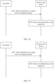
- the two MLDs may also perform link transition negotiation, so that the two MLDs may transition from a currently established link to a better link for communication.
- an embodiment of this application provides a multi-link reconfiguration method. As shown in FIG. 14 , the method includes the following steps.
- the query frame may be an existing BTM query frame. That is, the first MLD does not determine whether to perform link transition negotiation or BSS transition negotiation. Instead, the second MLD determines, according to an actual situation, whether to perform link transition negotiation or BSS transition negotiation.
- the first MLD may determine to perform link transition negotiation. Therefore, the query frame is used to negotiate link transition between the first MLD and the second MLD.
- the query frame may be a newly defined frame.
- the query frame may reuse an existing BTM query frame.
- the query frame may include one or more neighbor report elements. It should be understood that each neighbor report element corresponds to one AP adjacent to the first MLD.
- the neighbor report element may include a basic multi-link element, and the basic multi-link element may include a MAC address, a quantity of supported links, capability information, and the like of the AP MLD with which the AP adjacent to the first MLD is affiliated.
- the basic multi-link element in the neighbor report element may not include a per-link profile, to reduce signaling overheads.
- the query frame when the query frame reuses an existing BTM query frame, the query frame may include a multi-link element, and the query frame may determine, based on a type field in a multi-link control field in the multi-link element, that the query frame is used for link transition negotiation.
- the type field whose value is a second preset value indicates that the query frame is used to negotiate link transition between the first MLD and the second MLD.
- the second preset value is not 0 or 1.
- the second preset value may be the same as the foregoing first preset value. This is not limited.
- the query frame may further include a link identifier or a link bitmap that indicates a link with a high link frame loss rate.
- the second MLD may send an ACK frame to the first MLD.
- the request frame is used to request link transition between the first MLD and the second MLD.
- the request frame may be used to indicate a recommended link.
- the recommended link may also be referred to as a suggested link, a candidate link, or another name. This is not limited.
- the request frame may be a newly defined frame.
- the request frame may reuse an existing BTM request frame.
- the request mode field in the request frame may include a fourth field, and the fourth field may indicate a new request mode.
- the new request mode may be referred to as a link transition request mode, a link removal mode, or a link-level disassociation mode.
- the fourth field may use a reserved bit of the request mode field in the existing BTM frame.
- the fourth field may occupy one bit.
- FIG. 22 shows a frame structure of the request mode field of the request frame.
- the fourth field may be the link removal field in FIG. 22 .
- the request frame may include a multi-link element, and the request frame may determine, based on a type field in a multi-link control field in the multi-link element, that the request frame is used for link transition negotiation.
- the type field whose value is a second preset value indicates that the request frame is used to negotiate link transition between the first MLD and the second MLD.
- the second preset value is not 0 or 1.
- the second preset value may be the same as the foregoing first preset value. This is not limited.
- a value of a preferred candidate list included field in the request frame should be set to 0, to indicate that the request frame does not carry a preferred BSS transition candidate list.
- the request frame may include a transition candidate list field, and the transition candidate list field may include one or more neighbor report elements.
- Each neighbor report element corresponds to one AP adjacent to the second MLD.
- the response frame indicates whether to accept link transition between the first MLD and the second MLD.
- the second MLD may send an ACK frame to the second MLD.
- the multi-link reconfiguration variant multi-link element may not include a per-link profile.
- the multi-link reconfiguration variant multi-link element carries a per-link profile, a link ID, or a link bitmap of a corresponding link to indicate the target link.
- the fifth frame indicates that the first MLD is to remove the current link may be specifically implemented as follows:
- the fifth frame includes a reason code (reason code) field, where the reason code field indicates to remove the current link.
- a reason code (reason code) field
- a new value is added for the reason code field included in the fifth frame to indicate removal of the current link.
- the fifth frame may be a newly defined management frame, for example, a link removal notify (link removal notify) frame, instead of reusing an existing frame.
- a link removal notify link removal notify
- the first MLD may further send a disassociation frame defined in an existing standard on the target link, to disassociate from the conventional station and an MLD that does not receive the fifth frame previously.
- the first MLD sends a fifth frame on the target link in a broadcast manner.
- multiple stations may be configured for an MLD to support data transmission over multiple links.
- the MLD has a requirement for adding a station.
- the MLD may add one or more stations affiliated with the MLD, so as to share data transmission load.
- no corresponding solution is provided in the conventional technology.
- the sixth frame is used to indicate the first MLD to add a target station affiliated with the first MLD.
- the target station operates on a target link.
- the sixth frame may include information about the target station.
- the information about the target station includes a BSS operation parameter, BSS capability information, and the like.
- the sixth frame may reuse an existing frame.
- the sixth frame may reuse a beacon frame. That the sixth frame includes the information about the target station may be specifically implemented as follows: An ML element or a reduced neighbor report in the beacon frame includes the information about the target station.
- the first MLD sends the sixth frame in a beacon frame manner on all links supported by the first MLD.
- That the MLD adds a station affiliated with the MLD may also be described as follows:
- the MLD enables/activates the station affiliated with the MLD, or enables a BSS that the station is in charge. This is not limited.
- a communication apparatus includes a corresponding hardware structure and/or software module for performing each function.
- a person skilled in the art should be easily aware that, in combination with units and algorithm steps of the examples described in embodiments disclosed in this specification, this application can be implemented by hardware or a combination of hardware and computer software. Whether a function is performed by hardware or hardware driven by computer software depends on particular applications and design constraints of the technical solutions. A person skilled in the art may use different methods to implement the described functions for each particular application, but it should not be considered that the implementation goes beyond the scope of this application.
- the apparatus may be divided into functional modules based on the foregoing method examples.
- each functional module may be obtained through division based on each corresponding function, or two or more functions may be integrated into one functional module.
- the integrated module may be implemented in a form of hardware, or may be implemented in a form of a software functional module.
- module division is an example, and is merely a logical function division. In actual implementation, another division manner may be used.
- An example in which each functional module is obtained through division based on each corresponding function is used below for description.
- FIG. 16 shows a communication apparatus according to an embodiment of this application.
- the communication apparatus includes a processing module 101 and a communication module 102.
- the processing module 101 is configured to support the first MLD in performing step S 101 in FIG. 4 .
- the communication module 102 is configured to support the first MLD in performing step S102 in FIG. 4 , step S104 in FIG. 8 , steps S201 to S203 in FIG. 14 , step S301 in FIG. 18 , step S401 in FIG. 19 , steps S501 and S503 in FIG. 20 , and step S601 in FIG. 21 .
- the processing module 101 is configured to support the second MLD in performing step S 103 in FIG. 4 .
- the communication module 102 is configured to support the second MLD in performing step S102 in FIG. 4 , step S104 in FIG. 8 , steps S201 to S203 in FIG. 14 , step S302 in FIG. 18 , step S402 in FIG. 19 , steps S502 and S504 in FIG. 20 , and step S602 in FIG. 21 .
- FIG. 17 is a diagram of a structure of a possible product form of a communication apparatus according to an embodiment of this application.
- the communication apparatus in this embodiment of this application may be a multi-link device, and the multi-link device includes a processor 201 and a transceiver 202.
- the multi-link device further includes a memory 203.
- the processor 201 is configured to support the first MLD in performing step S101 in FIG. 4 .
- the transceiver 202 is configured to support the first MLD in performing step S102 in FIG. 4 , step S104 in FIG. 8 , steps S201 to S203 in FIG. 14 , step S301 in FIG. 18 , step S401 in FIG. 19 , steps S501 and S503 in FIG. 20 , and step S601 in FIG. 21 .
- the communication apparatus described in embodiments of this application may be implemented by using a chip.
- the chip includes a processing circuit 201 and a transceiver pin 202.
- the chip may further include a storage medium 203.
- the communication apparatus described in this embodiment of this application may alternatively be implemented by using the following circuit or component: one or more field programmable gate arrays (field programmable gate array, FPGA), a programmable logic device (programmable logic device, PLD), a controller, a state machine, gate logic, a discrete hardware component, any other suitable circuits, or any combination of circuits that can perform various functions described in this application.
- FPGA field programmable gate array
- PLD programmable logic device
- controller a state machine, gate logic, a discrete hardware component, any other suitable circuits, or any combination of circuits that can perform various functions described in this application.
- an embodiment of this application further provides a computer-readable storage medium.
- the computer-readable storage medium stores computer instructions.
- the computer instructions run on a computer, the computer is enabled to perform the methods in the foregoing method embodiments.
- an embodiment of this application further provides a computer program product including computer instructions.
- the computer instructions run on a computer, the computer is enabled to perform the methods in the foregoing method embodiments.
- the apparatus and method disclosed in the several embodiments provided in this application may be implemented in other manners.
- the described apparatus embodiments are merely examples.
- the division into modules or units is merely logical function division and may be other division during actual implementation.
- a plurality of units or components may be combined or integrated into another apparatus, or some features may be ignored or not performed.
- the displayed or discussed mutual couplings or direct couplings or communication connections may be implemented through some interfaces.
- the indirect couplings or communication connections between the apparatuses or units may be implemented in electrical, mechanical, or another form.
- each of the units may exist alone physically, or two or more units may be integrated into one unit.
- the integrated unit may be implemented in a form of hardware, or may be implemented in a form of a software functional unit.
- the integrated unit When the integrated unit is implemented in the form of a software functional unit and sold or used as an independent product, the integrated unit may be stored in a readable storage medium. Based on such an understanding, the technical solutions of this application essentially, or the part contributing to the prior art, or all or some of the technical solutions may be implemented in the form of a software product.
- the software product is stored in a storage medium and includes several instructions for instructing a device (which may be a single-chip microcomputer, a chip or the like) or a processor (processor) to perform all or some of the steps of the methods described in embodiments of this application.
Landscapes
- Engineering & Computer Science (AREA)
- Computer Networks & Wireless Communication (AREA)
- Signal Processing (AREA)
- Mobile Radio Communication Systems (AREA)
- Logic Circuits (AREA)
- Coupling Device And Connection With Printed Circuit (AREA)
- Paper (AREA)
- Vehicle Body Suspensions (AREA)
Applications Claiming Priority (4)
| Application Number | Priority Date | Filing Date | Title |
|---|---|---|---|
| CN202110058021 | 2021-01-15 | ||
| CN202110713587 | 2021-06-25 | ||
| CN202110778961.5A CN114765904A (zh) | 2021-01-15 | 2021-07-09 | 多链路的重配置方法及装置 |
| PCT/CN2022/071673 WO2022152184A1 (fr) | 2021-01-15 | 2022-01-12 | Procédé et appareil de reconfiguration à liaisons multiples |
Related Child Applications (1)
| Application Number | Title | Priority Date | Filing Date |
|---|---|---|---|
| EP26159254.7 Division-Into | 2026-02-18 |
Publications (3)
| Publication Number | Publication Date |
|---|---|
| EP4199637A1 true EP4199637A1 (fr) | 2023-06-21 |
| EP4199637A4 EP4199637A4 (fr) | 2024-05-29 |
| EP4199637B1 EP4199637B1 (fr) | 2026-04-22 |
Family
ID=82364742
Family Applications (1)
| Application Number | Title | Priority Date | Filing Date |
|---|---|---|---|
| EP22739062.2A Active EP4199637B1 (fr) | 2021-01-15 | 2022-01-12 | Procédé et appareil de reconfiguration à liaisons multiples |
Country Status (9)
| Country | Link |
|---|---|
| US (2) | US12232200B2 (fr) |
| EP (1) | EP4199637B1 (fr) |
| JP (2) | JP7618815B2 (fr) |
| KR (1) | KR20230107341A (fr) |
| CN (4) | CN114765904A (fr) |
| AU (3) | AU2022207565B2 (fr) |
| CA (1) | CA3200638A1 (fr) |
| MX (1) | MX2023004546A (fr) |
| WO (1) | WO2022152184A1 (fr) |
Families Citing this family (16)
| Publication number | Priority date | Publication date | Assignee | Title |
|---|---|---|---|---|
| CN114765904A (zh) * | 2021-01-15 | 2022-07-19 | 华为技术有限公司 | 多链路的重配置方法及装置 |
| US20220255690A1 (en) * | 2021-02-09 | 2022-08-11 | Mediatek Singapore Pte. Ltd. | Signaling For UL TB PPDU With Distributed-Tone Resource Units In 6GHz Low-Power Indoor Systems |
| EP4333547A4 (fr) * | 2021-06-01 | 2024-10-23 | LG Electronics Inc. | Procédé et dispositif pour demander les mêmes informations partielles pour toutes les stations de transmission à l'intérieur d'un mld de transmission et répondre à celles-ci dans un système lan sans fil |
| WO2023245678A1 (fr) * | 2022-06-24 | 2023-12-28 | Oppo广东移动通信有限公司 | Procédé et appareil de reconfiguration à liaisons multiples, et dispositif de communication |
| US20240048650A1 (en) * | 2022-08-04 | 2024-02-08 | Tishrea Johnson | Frame Tracker Device |
| CN118592085B (zh) * | 2023-01-03 | 2025-06-24 | 北京小米移动软件有限公司 | 通信方法、电子设备及存储介质 |
| CN119278647A (zh) * | 2023-05-04 | 2025-01-07 | 北京小米移动软件有限公司 | 操作参数协商方法、电子设备及存储介质 |
| US12513511B2 (en) * | 2023-05-12 | 2025-12-30 | Cisco Technology, Inc. | Using 802.11v action report messages to enhance roaming |
| CN119325118B (zh) * | 2023-05-31 | 2025-11-18 | 华为技术有限公司 | Btm中的信息指示方法及装置 |
| CN121865355A (zh) * | 2023-08-02 | 2026-04-14 | Oppo广东移动通信有限公司 | 切换方法、装置、设备、介质和程序产品 |
| US20250063631A1 (en) * | 2023-08-14 | 2025-02-20 | Samsung Electronics Co., Ltd. | Multi-link operation in wireless networks |
| US20250089121A1 (en) * | 2023-09-08 | 2025-03-13 | Cisco Technology, Inc. | Multi-link procedure to identify link disablement in basic service set (bss) transition management frames |
| CN120034887A (zh) * | 2023-11-22 | 2025-05-23 | 华为技术有限公司 | 用于感知测量的方法和通信装置 |
| WO2025137470A1 (fr) * | 2023-12-20 | 2025-06-26 | Cisco Technology, Inc. | Opération de liaison de commutation à l'intérieur et à travers des dispositifs à liaisons multiples dans un réseau wi-fi |
| WO2025163807A1 (fr) * | 2024-01-31 | 2025-08-07 | Ntt株式会社 | Point d'accès et dispositif terminal |
| US12439470B2 (en) * | 2024-02-02 | 2025-10-07 | Cisco Technology, Inc. | Signaling multi-link device capabilities |
Family Cites Families (17)
| Publication number | Priority date | Publication date | Assignee | Title |
|---|---|---|---|---|
| CN113709077B (zh) | 2016-02-29 | 2023-11-10 | 松下电器(美国)知识产权公司 | 发送装置、发送方法 |
| CN108064058B (zh) | 2016-11-07 | 2022-11-01 | 中兴通讯股份有限公司 | 拥塞控制方法及装置、基站 |
| US10856203B2 (en) * | 2017-01-19 | 2020-12-01 | Qualcomm Incorporated | Signaling for link aggregation setup and reconfiguration |
| DE102017117130A1 (de) | 2017-07-28 | 2019-01-31 | Ebm-Papst Mulfingen Gmbh & Co. Kg | Drahtlosübertragung |
| WO2019040092A1 (fr) * | 2017-08-24 | 2019-02-28 | Intel IP Corporation | Double connectivité pour 6 ghz |
| US10959153B2 (en) * | 2017-09-11 | 2021-03-23 | Qualcomm Incorporated | Techniques for multi-link aggregation signaling |
| US11032207B2 (en) * | 2017-11-17 | 2021-06-08 | Qualcomm Incorporated | Link aggregation with floating primary link |
| US11153921B2 (en) * | 2018-11-19 | 2021-10-19 | Mediatek Inc. | Method and apparatus for link enablement and disablement during multi-link operation in a wireless network |
| CN111586667B (zh) * | 2019-02-15 | 2022-01-14 | 华为技术有限公司 | 通信方法及终端设备、核心网设备 |
| CN118338464B (zh) * | 2019-05-25 | 2025-10-10 | 华为技术有限公司 | 一种适用于多链路的通信方法及相关设备 |
| CN120730548A (zh) * | 2019-07-05 | 2025-09-30 | 华为技术有限公司 | 一种多链路通信方法及相关设备 |
| US11445431B2 (en) * | 2019-07-12 | 2022-09-13 | Qualcomm Incorporated | Multi-link communication |
| SG10202002245YA (en) * | 2020-03-11 | 2021-10-28 | Panasonic Ip Corp America | Communication apparatus and communication method for multi-link setup and link maintenance |
| US11743709B2 (en) * | 2020-04-08 | 2023-08-29 | Qualcomm Incorporated | Context updates for multi-link devices |
| CN113676298B (zh) * | 2020-05-14 | 2023-08-08 | 华为技术有限公司 | 多链路通信方法及相关装置 |
| US20220124855A1 (en) * | 2020-10-15 | 2022-04-21 | Facebook Technologies, Llc | Methods and systems for multi-link operations |
| CN114765904A (zh) * | 2021-01-15 | 2022-07-19 | 华为技术有限公司 | 多链路的重配置方法及装置 |
-
2021
- 2021-07-09 CN CN202110778961.5A patent/CN114765904A/zh active Pending
- 2021-07-09 CN CN202310192905.2A patent/CN116234069B/zh active Active
- 2021-07-09 CN CN202310165719.XA patent/CN116234068B/zh active Active
- 2021-07-09 CN CN202510406602.5A patent/CN120264501A/zh active Pending
-
2022
- 2022-01-12 JP JP2023539361A patent/JP7618815B2/ja active Active
- 2022-01-12 AU AU2022207565A patent/AU2022207565B2/en active Active
- 2022-01-12 KR KR1020237020374A patent/KR20230107341A/ko active Pending
- 2022-01-12 CA CA3200638A patent/CA3200638A1/fr active Pending
- 2022-01-12 MX MX2023004546A patent/MX2023004546A/es unknown
- 2022-01-12 EP EP22739062.2A patent/EP4199637B1/fr active Active
- 2022-01-12 WO PCT/CN2022/071673 patent/WO2022152184A1/fr not_active Ceased
-
2023
- 2023-04-04 US US18/295,270 patent/US12232200B2/en active Active
-
2024
- 2024-12-12 AU AU2024278340A patent/AU2024278340B2/en active Active
-
2025
- 2025-01-07 JP JP2025002280A patent/JP7835913B2/ja active Active
- 2025-01-26 US US19/037,202 patent/US20250234405A1/en active Pending
-
2026
- 2026-03-16 AU AU2026201982A patent/AU2026201982A1/en active Pending
Also Published As
| Publication number | Publication date |
|---|---|
| JP2025063124A (ja) | 2025-04-15 |
| US12232200B2 (en) | 2025-02-18 |
| AU2022207565A1 (en) | 2023-04-06 |
| AU2024278340A1 (en) | 2025-01-09 |
| CN116234069A (zh) | 2023-06-06 |
| CN116234068A (zh) | 2023-06-06 |
| CN114765904A (zh) | 2022-07-19 |
| AU2022207565B2 (en) | 2024-10-03 |
| WO2022152184A1 (fr) | 2022-07-21 |
| AU2026201982A1 (en) | 2026-04-02 |
| CA3200638A1 (fr) | 2022-07-21 |
| US20230247703A1 (en) | 2023-08-03 |
| CN120264501A (zh) | 2025-07-04 |
| US20250234405A1 (en) | 2025-07-17 |
| JP7618815B2 (ja) | 2025-01-21 |
| EP4199637A4 (fr) | 2024-05-29 |
| JP2024503592A (ja) | 2024-01-26 |
| EP4199637B1 (fr) | 2026-04-22 |
| CN116234068B (zh) | 2026-01-23 |
| JP7835913B2 (ja) | 2026-03-25 |
| CN116234069B (zh) | 2023-12-08 |
| AU2024278340B2 (en) | 2025-12-18 |
| KR20230107341A (ko) | 2023-07-14 |
| MX2023004546A (es) | 2023-05-08 |
Similar Documents
| Publication | Publication Date | Title |
|---|---|---|
| EP4199637A1 (fr) | Procédé et appareil de reconfiguration à liaisons multiples | |
| EP4145947A1 (fr) | Procédé d'association provisoire à liaisons multiples et appareil associé | |
| EP4383836A1 (fr) | Procédé et appareil de communication | |
| US9992815B2 (en) | Method of performing handover procedure, making handover decision for device-to-device communications and control node thereof | |
| EP3331275B1 (fr) | Procédé de notification de transfert intercellulaire de canal de réseau local sans fil assisté par réseau cellulaire | |
| WO2022253791A1 (fr) | Procédés de communication, dispositif et support lisible par ordinateur non transitoire pour signaler des liaisons emlmr et des ensembles de liaisons emlmr associées | |
| US20250126638A1 (en) | Power state determining method and apparatus | |
| US20070291681A1 (en) | Method and apparatus for providing information about each group address that has data waiting for delivery in node, point or terminal in a WLAN | |
| EP1955128A2 (fr) | Intervalles d'ecoute de diffusion et/ou de multidiffusion souples | |
| US20070127478A1 (en) | Flexible multicast and/or broadcast listening intervals | |
| TW202428064A (zh) | 通信的方法和通信裝置 | |
| CN116782152A (zh) | 一种多链路数据处理方法、装置及设备 | |
| GB2631801A (en) | Improved coexistence link information report | |
| RU2822824C1 (ru) | Способ и аппаратура для реконфигурирования многоканальных соединений | |
| CN117412250A (zh) | 在rrc非活动状态下的接收多播服务的方法和装置 | |
| HK40122427A (zh) | 多链路的重配置方法及装置 | |
| WO2025011958A1 (fr) | Rapport d'informations de liaison de coexistence amélioré | |
| WO2025139708A1 (fr) | Procédé de communication et appareil de communication | |
| WO2025035240A1 (fr) | Procédé d'intégration pour nœud d'accès et de liaison terrestre intégrés, et appareil | |
| CN116634607A (zh) | 多链路设备以及通信方法 |
Legal Events
| Date | Code | Title | Description |
|---|---|---|---|
| STAA | Information on the status of an ep patent application or granted ep patent |
Free format text: STATUS: THE INTERNATIONAL PUBLICATION HAS BEEN MADE |
|
| PUAI | Public reference made under article 153(3) epc to a published international application that has entered the european phase |
Free format text: ORIGINAL CODE: 0009012 |
|
| STAA | Information on the status of an ep patent application or granted ep patent |
Free format text: STATUS: REQUEST FOR EXAMINATION WAS MADE |
|
| 17P | Request for examination filed |
Effective date: 20230316 |
|
| AK | Designated contracting states |
Kind code of ref document: A1 Designated state(s): AL AT BE BG CH CY CZ DE DK EE ES FI FR GB GR HR HU IE IS IT LI LT LU LV MC MK MT NL NO PL PT RO RS SE SI SK SM TR |
|
| DAV | Request for validation of the european patent (deleted) | ||
| DAX | Request for extension of the european patent (deleted) | ||
| A4 | Supplementary search report drawn up and despatched |
Effective date: 20240426 |
|
| RIC1 | Information provided on ipc code assigned before grant |
Ipc: H04W 84/12 20090101ALN20240422BHEP Ipc: H04W 76/30 20180101ALI20240422BHEP Ipc: H04W 76/34 20180101ALI20240422BHEP Ipc: H04W 76/19 20180101ALI20240422BHEP Ipc: H04W 76/15 20180101AFI20240422BHEP |
|
| STAA | Information on the status of an ep patent application or granted ep patent |
Free format text: STATUS: EXAMINATION IS IN PROGRESS |
|
| 17Q | First examination report despatched |
Effective date: 20250217 |
|
| GRAP | Despatch of communication of intention to grant a patent |
Free format text: ORIGINAL CODE: EPIDOSNIGR1 |
|
| STAA | Information on the status of an ep patent application or granted ep patent |
Free format text: STATUS: GRANT OF PATENT IS INTENDED |
|
| RIC1 | Information provided on ipc code assigned before grant |
Ipc: H04W 84/12 20090101ALN20250508BHEP Ipc: H04W 76/30 20180101ALI20250508BHEP Ipc: H04W 76/34 20180101ALI20250508BHEP Ipc: H04W 76/19 20180101ALI20250508BHEP Ipc: H04W 76/15 20180101AFI20250508BHEP |
|
| INTG | Intention to grant announced |
Effective date: 20250514 |
|
| GRAJ | Information related to disapproval of communication of intention to grant by the applicant or resumption of examination proceedings by the epo deleted |
Free format text: ORIGINAL CODE: EPIDOSDIGR1 |
|
| STAA | Information on the status of an ep patent application or granted ep patent |
Free format text: STATUS: EXAMINATION IS IN PROGRESS |
|
| GRAP | Despatch of communication of intention to grant a patent |
Free format text: ORIGINAL CODE: EPIDOSNIGR1 |
|
| STAA | Information on the status of an ep patent application or granted ep patent |
Free format text: STATUS: GRANT OF PATENT IS INTENDED |
|
| INTC | Intention to grant announced (deleted) | ||
| RIC1 | Information provided on ipc code assigned before grant |
Ipc: H04W 76/15 20180101AFI20250825BHEP Ipc: H04W 76/19 20180101ALI20250825BHEP Ipc: H04W 76/34 20180101ALI20250825BHEP Ipc: H04W 76/30 20180101ALI20250825BHEP Ipc: H04W 84/12 20090101ALN20250825BHEP |
|
| INTG | Intention to grant announced |
Effective date: 20250908 |
|
| GRAJ | Information related to disapproval of communication of intention to grant by the applicant or resumption of examination proceedings by the epo deleted |
Free format text: ORIGINAL CODE: EPIDOSDIGR1 |
|
| STAA | Information on the status of an ep patent application or granted ep patent |
Free format text: STATUS: EXAMINATION IS IN PROGRESS |
|
| GRAP | Despatch of communication of intention to grant a patent |
Free format text: ORIGINAL CODE: EPIDOSNIGR1 |
|
| STAA | Information on the status of an ep patent application or granted ep patent |
Free format text: STATUS: GRANT OF PATENT IS INTENDED |
|
| INTC | Intention to grant announced (deleted) | ||
| RIC1 | Information provided on ipc code assigned before grant |
Ipc: H04W 76/15 20180101AFI20251113BHEP Ipc: H04W 76/19 20180101ALI20251113BHEP Ipc: H04W 76/34 20180101ALI20251113BHEP Ipc: H04W 76/30 20180101ALI20251113BHEP Ipc: H04W 84/12 20090101ALN20251113BHEP |
|
| INTG | Intention to grant announced |
Effective date: 20251124 |
|
| GRAS | Grant fee paid |
Free format text: ORIGINAL CODE: EPIDOSNIGR3 |
|
| GRAA | (expected) grant |
Free format text: ORIGINAL CODE: 0009210 |
|
| STAA | Information on the status of an ep patent application or granted ep patent |
Free format text: STATUS: THE PATENT HAS BEEN GRANTED |
|
| AK | Designated contracting states |
Kind code of ref document: B1 Designated state(s): AL AT BE BG CH CY CZ DE DK EE ES FI FR GB GR HR HU IE IS IT LI LT LU LV MC MK MT NL NO PL PT RO RS SE SI SK SM TR |
|
| REG | Reference to a national code |
Ref country code: CH Ref legal event code: F10 Free format text: ST27 STATUS EVENT CODE: U-0-0-F10-F00 (AS PROVIDED BY THE NATIONAL OFFICE) Effective date: 20260422 Ref country code: GB Ref legal event code: FG4D |