EP4199669A1 - Wärmeableitungsanordnung und kraftfahrzeug - Google Patents
Wärmeableitungsanordnung und kraftfahrzeug Download PDFInfo
- Publication number
- EP4199669A1 EP4199669A1 EP21859932.2A EP21859932A EP4199669A1 EP 4199669 A1 EP4199669 A1 EP 4199669A1 EP 21859932 A EP21859932 A EP 21859932A EP 4199669 A1 EP4199669 A1 EP 4199669A1
- Authority
- EP
- European Patent Office
- Prior art keywords
- plate
- temperature equalization
- liquid cold
- main board
- cold plate
- Prior art date
- Legal status (The legal status is an assumption and is not a legal conclusion. Google has not performed a legal analysis and makes no representation as to the accuracy of the status listed.)
- Pending
Links
Images

Classifications
-
- H—ELECTRICITY
- H05—ELECTRIC TECHNIQUES NOT OTHERWISE PROVIDED FOR
- H05K—PRINTED CIRCUITS; CASINGS OR CONSTRUCTIONAL DETAILS OF ELECTRIC APPARATUS; MANUFACTURE OF ASSEMBLAGES OF ELECTRICAL COMPONENTS
- H05K1/00—Printed circuits
- H05K1/02—Details
- H05K1/0201—Thermal arrangements, e.g. for cooling, heating or preventing overheating
- H05K1/0203—Cooling of mounted components
- H05K1/0207—Cooling of mounted components using internal conductor planes parallel to the surface for thermal conduction, e.g. power planes
-
- H—ELECTRICITY
- H05—ELECTRIC TECHNIQUES NOT OTHERWISE PROVIDED FOR
- H05K—PRINTED CIRCUITS; CASINGS OR CONSTRUCTIONAL DETAILS OF ELECTRIC APPARATUS; MANUFACTURE OF ASSEMBLAGES OF ELECTRICAL COMPONENTS
- H05K7/00—Constructional details common to different types of electric apparatus
- H05K7/20—Modifications to facilitate cooling, ventilating, or heating
- H05K7/20845—Modifications to facilitate cooling, ventilating, or heating for automotive electronic casings
- H05K7/20872—Liquid coolant without phase change
-
- B—PERFORMING OPERATIONS; TRANSPORTING
- B60—VEHICLES IN GENERAL
- B60R—VEHICLES, VEHICLE FITTINGS, OR VEHICLE PARTS, NOT OTHERWISE PROVIDED FOR
- B60R16/00—Electric or fluid circuits specially adapted for vehicles and not otherwise provided for; Arrangement of elements of electric or fluid circuits specially adapted for vehicles and not otherwise provided for
-
- H—ELECTRICITY
- H05—ELECTRIC TECHNIQUES NOT OTHERWISE PROVIDED FOR
- H05K—PRINTED CIRCUITS; CASINGS OR CONSTRUCTIONAL DETAILS OF ELECTRIC APPARATUS; MANUFACTURE OF ASSEMBLAGES OF ELECTRICAL COMPONENTS
- H05K1/00—Printed circuits
- H05K1/02—Details
- H05K1/0201—Thermal arrangements, e.g. for cooling, heating or preventing overheating
- H05K1/0203—Cooling of mounted components
- H05K1/0209—External configuration of printed circuit board adapted for heat dissipation, e.g. lay-out of conductors, coatings
-
- H—ELECTRICITY
- H05—ELECTRIC TECHNIQUES NOT OTHERWISE PROVIDED FOR
- H05K—PRINTED CIRCUITS; CASINGS OR CONSTRUCTIONAL DETAILS OF ELECTRIC APPARATUS; MANUFACTURE OF ASSEMBLAGES OF ELECTRICAL COMPONENTS
- H05K7/00—Constructional details common to different types of electric apparatus
- H05K7/20—Modifications to facilitate cooling, ventilating, or heating
- H05K7/20218—Modifications to facilitate cooling, ventilating, or heating using a liquid coolant without phase change in electronic enclosures
- H05K7/20254—Cold plates transferring heat from heat source to coolant
-
- H—ELECTRICITY
- H10—SEMICONDUCTOR DEVICES; ELECTRIC SOLID-STATE DEVICES NOT OTHERWISE PROVIDED FOR
- H10W—GENERIC PACKAGES, INTERCONNECTIONS, CONNECTORS OR OTHER CONSTRUCTIONAL DETAILS OF DEVICES COVERED BY CLASS H10
- H10W40/00—Arrangements for thermal protection or thermal control
- H10W40/20—Arrangements for cooling
- H10W40/22—Arrangements for cooling characterised by their shape, e.g. having conical or cylindrical projections
-
- H—ELECTRICITY
- H10—SEMICONDUCTOR DEVICES; ELECTRIC SOLID-STATE DEVICES NOT OTHERWISE PROVIDED FOR
- H10W—GENERIC PACKAGES, INTERCONNECTIONS, CONNECTORS OR OTHER CONSTRUCTIONAL DETAILS OF DEVICES COVERED BY CLASS H10
- H10W40/00—Arrangements for thermal protection or thermal control
- H10W40/20—Arrangements for cooling
- H10W40/25—Arrangements for cooling characterised by their materials
-
- H—ELECTRICITY
- H10—SEMICONDUCTOR DEVICES; ELECTRIC SOLID-STATE DEVICES NOT OTHERWISE PROVIDED FOR
- H10W—GENERIC PACKAGES, INTERCONNECTIONS, CONNECTORS OR OTHER CONSTRUCTIONAL DETAILS OF DEVICES COVERED BY CLASS H10
- H10W40/00—Arrangements for thermal protection or thermal control
- H10W40/40—Arrangements for thermal protection or thermal control involving heat exchange by flowing fluids
- H10W40/47—Arrangements for thermal protection or thermal control involving heat exchange by flowing fluids by flowing liquids, e.g. forced water cooling
-
- H—ELECTRICITY
- H10—SEMICONDUCTOR DEVICES; ELECTRIC SOLID-STATE DEVICES NOT OTHERWISE PROVIDED FOR
- H10W—GENERIC PACKAGES, INTERCONNECTIONS, CONNECTORS OR OTHER CONSTRUCTIONAL DETAILS OF DEVICES COVERED BY CLASS H10
- H10W40/00—Arrangements for thermal protection or thermal control
- H10W40/70—Fillings or auxiliary members in containers or in encapsulations for thermal protection or control
- H10W40/73—Fillings or auxiliary members in containers or in encapsulations for thermal protection or control for cooling by change of state
-
- Y—GENERAL TAGGING OF NEW TECHNOLOGICAL DEVELOPMENTS; GENERAL TAGGING OF CROSS-SECTIONAL TECHNOLOGIES SPANNING OVER SEVERAL SECTIONS OF THE IPC; TECHNICAL SUBJECTS COVERED BY FORMER USPC CROSS-REFERENCE ART COLLECTIONS [XRACs] AND DIGESTS
- Y02—TECHNOLOGIES OR APPLICATIONS FOR MITIGATION OR ADAPTATION AGAINST CLIMATE CHANGE
- Y02D—CLIMATE CHANGE MITIGATION TECHNOLOGIES IN INFORMATION AND COMMUNICATION TECHNOLOGIES [ICT], I.E. INFORMATION AND COMMUNICATION TECHNOLOGIES AIMING AT THE REDUCTION OF THEIR OWN ENERGY USE
- Y02D10/00—Energy efficient computing, e.g. low power processors, power management or thermal management
Definitions
- This application relates to the field of hardware structure technologies, and in particular, to a heat dissipation assembly and a vehicle.
- a printed circuit board (printed circuit board, PCB) arranged with an artificial intelligence (artificial intelligence, AI) chip (which may also be referred to as an AI daughter board) is mounted on a main board by using a connector.
- AI daughter board has a specific computing power.
- a quantity of mounted AI boards is determined based on a computing power required by a customer, and data reasoning or data analysis may be flexibly configured.
- a liquid cold plate may be placed between the main board and the daughter board to dissipate heat from a heat emitting device on the main board.
- Main heat emitting devices on the main board and the daughter board are attached to the liquid cold plate for heat dissipation. Heat from the heat emitting devices may be dissipated by using the liquid cold plate, thereby resolving a problem that it is difficult to dissipate heat from a device between the daughter board and the main board.
- the liquid cold plate has a limited thickness and a poor heat dissipation capability due to a small space between the daughter board and the main board. Consequently, it is difficult to support heat dissipation of a main chip with large power consumption.
- a capacitor and an inductor that are between a daughter board connector and both of the main board and the daughter board need to pass through the liquid cold plate.
- a runner in the liquid cold plate is interrupted. Consequently, the heat dissipation capability of the liquid cold plate is degraded.
- this application provides a heat dissipation assembly, including a liquid cold plate, a temperature equalization plate, and a thermally conductive assembly, where one side of the temperature equalization plate is attached to a heat emitting device on a main board; the liquid cold plate is disposed on a side that is of the temperature equalization plate and that is away from the main board; a PCB board is fastened between the temperature equalization plate and the liquid cold plate, a connector is fastened on the PCB board, one end of the connector is connected to the PCB board, the connector passes through the temperature equalization plate, and the other end of the connector extends to the main board and is fastened on the main board; and the liquid cold plate is connected to the temperature equalization plate by using the thermally conductive assembly, so that heat generated by the heat emitting device is transferred to the liquid cold plate by using the temperature equalization plate and the thermally conductive assembly.
- the temperature equalization plate may be a thin copper plate with good thermal conductivity, a thin aluminum plate welded with a heat pipe, a thin flat heat pipe, a graphene sheet, or the like. This is not limited in this application.
- the heat emitting device may be a device, for example, an SOC (System on Chip), a local area network switch LAN SW, or a microcontroller unit.
- the liquid cold plate may be of a structure that has thermal conduction and heat dissipation functions.
- the liquid cold plate is a metal plate.
- the liquid cold plate is an aluminum alloy material or a steel plate.
- the liquid cold plate may alternatively be another thermally conductive material, for example, a ceramic plate or plastic having a thermal conduction capability.
- the liquid cold plate may include a pipeline, and the pipeline may be filled with liquid, so that heat is removed through liquid flowing.
- the liquid may be water or another refrigerant.
- the PCB board arranged with an AI chip may be fastened on the main board.
- the liquid cold plate is disposed between the PCB board arranged with the AI chip and the main board to dissipate heat from the PCB board arranged with the AI chip and the heat emitting device on the main board.
- the PCB board arranged with the AI chip is connected to the main board by using the connector, the connector affects a structure of the liquid cold plate, and a distance between the PCB board arranged with the AI chip and the main board is excessively small. Consequently, a thickness of the liquid cold plate is limited, and heat dissipation efficiency is low.
- the liquid cold plate is disposed on a side that is of the PCB board and that is away from the main board, and the connector passes through only the temperature equalization plate between the main board and the PCB board without passing through the liquid cold plate. Because the temperature equalization plate conducts heat by using metal and does not have a runner inside, a problem that a heat dissipation capability is significantly degraded because a runner is interrupted does not exists, thereby improving heat dissipation performance of the liquid cold plate.
- one end of the thermally conductive assembly is fastened to the liquid cold plate, and the other end of the thermally conductive assembly extends to the temperature equalization plate and is connected to the temperature equalization plate.
- a central area of the temperature equalization plate is attached to the heat emitting device on the main board, and an edge area of the temperature equalization plate extends to the main board and is fastened on the main board.
- the temperature equalization plate is of a "cover-shaped" structure.
- the central area of the temperature equalization plate protrudes in a direction away from the main board to form a hollowed area.
- An inner wall of the hollowed area may be attached to the heat emitting device, and the edge area of the temperature equalization plate is fastened to the main board, so that heat on the main board can be transferred to the temperature equalization plate.
- the "central area” and the "edge area” are relative position expressions, and are not absolute position limitations.
- the central area of the temperature equalization plate is closer to a center of the temperature equalization plate relative to the edge area.
- a non-edge area of the temperature equalization plate may alternatively be fastened to the main board, provided that it can be ensured that the temperature equalization plate is fastened to the main board, and an area for the heat emitting device can be reserved between the temperature equalization plate and the main board.
- a fastening manner between the temperature equalization plate and the main board is not limited in this application.
- an SOC is arranged on the PCB board.
- the SOC is arranged on a side that is of the PCB board and that faces the liquid cold plate, and the SOC is attached to the liquid cold plate.
- heat generated by the SOC on the PCB board or another heat emitting device can be directly transferred to the liquid cold plate.
- the SOC is arranged on a side that is of the PCB board and that faces the temperature equalization plate, and the SOC is attached to the temperature equalization plate.
- heat generated by the SOC on the PCB board or another heat emitting device can be transferred to the temperature equalization plate, and be further transferred to the liquid cold plate by using the temperature equalization plate and the thermally conductive assembly.
- this application provides a vehicle-mounted computing apparatus mounting method, including:
- this application provides a vehicle, including a vehicle body and the heat dissipation assembly that is in any implementation of the first aspect and that is disposed in the vehicle body.
- An embodiment of this application provides a heat dissipation assembly, including a liquid cold plate, a temperature equalization plate, and a thermally conductive assembly, where one side of the temperature equalization plate is attached to a heat emitting device on a main board; the liquid cold plate is disposed on a side that is of the temperature equalization plate and that is away from the main board; and the liquid cold plate is connected to the temperature equalization plate by using the thermally conductive assembly, so that heat generated by the heat emitting device is transferred to the liquid cold plate by using the temperature equalization plate and the thermally conductive assembly.
- the temperature equalization plate is added to the main board, and the liquid cold plate is disposed on the side that is of the temperature equalization plate and that is away from the main board.
- the temperature equalization plate transfers the heat of the heat emitting device on the main board to the liquid cold plate.
- a PCB board may be disposed between the temperature equalization plate and the liquid cold plate, so that a runner in the liquid cold plate is not interrupted by a connector between the PCB board and the main board, thereby improving heat dissipation performance of the liquid cold plate.
- the heat dissipation assembly provided in this application may be used in a vehicle.
- the heat dissipation assembly may be used in a vehicle-mounted computing apparatus in a vehicle.
- the vehicle-mounted computing apparatus may be applied to automated driving (automated driving) of an intelligent vehicle.
- the intelligent vehicle includes an electric vehicle that supports unmanned driving (unmanned driving), driver assistance (driver assistance/ADAS), intelligent driving (intelligent driving), connected driving (connected driving), intelligent network driving (intelligent network driving), and car sharing (car sharing), or a gasoline-driven vehicle.
- the vehicle-mounted computing apparatus is configured to perform driving state control and state monitoring on the intelligent vehicle, and includes but is not limited to a vehicle-mounted mobile data center (mobile data center, MDC), a hardware monitor interface (hardware monitor interface, HMI) that implements a man-machine interaction controller function, an in-vehicle infotainment (in-vehicle infotainment, IVI) controller, a body control module (body control module, BCM), or a vehicle control unit (vehicle control unit, VCU).
- the vehicle-mounted computing apparatus may be specifically a chip with computing and processing capabilities, or may be a set that is of a plurality of devices such as a processor and a memory and that is integrated in a printed circuit board (printed circuit board, PCB).
- the processor includes but is not limited to a central processing unit (central processing unit, CPU), a general-purpose processor, a digital signal processor (digital signal processor, DSP), an application-specific integrated circuit (application-specific integrated circuit, ASIC), a field-programmable gate array (field-programmable gate array, FPGA) or another programmable logic device, a discrete gate or transistor logic device, a discrete hardware assembly, a graphics processing unit (graphics processing unit, GPU), or an artificial intelligence (artificial intelligence, AI) chip.
- the general-purpose processor may be a microprocessor, or may be any conventional processor or the like. It can be learned from the foregoing description that a chip with large computation amount is disposed in the vehicle-mounted computing apparatus. Therefore, the chip has a high requirement for heat dissipation when being used. Therefore, this application provides a heat dissipation assembly to improve a heat dissipation effect of the chip in the vehicle-mounted computing apparatus.
- a vehicle-mounted computing apparatus 201 may be mounted at a proper position, for example, in a center console or near a vehicle liquid cooling pump, to detect, by using various sensors (for example, a millimeter-wave radar 206, a lidar 205, and a camera 202) mounted on a vehicle body, an environment in which a vehicle is located, then the environment is fed back to a chip and the like built in the vehicle-mounted computing apparatus 201 for real-time reasoning operation, and finally, the vehicle-mounted computing apparatus 201 delivers an operation command to a vehicle control unit (vehicle control unit, VCiJ) 204, so that the VCU 204 controls and maneuvers (brakes, decelerates, and the like) the vehicle, to implement automated driving functions of various levels.
- vehicle control unit vehicle control unit
- the vehicle-mounted computing apparatus 201 may further upload data to a cloud data center at a back end by using a T-BOX (telematics BOX) 203.
- the vehicle-mounted computing apparatus 201 may perform transmission with the camera 202 through a multimedia serial link (multimedia serial link, MSL), perform transmission with the lidar 205 through a vehicle-mounted Ethernet link, perform transmission with the VCU 204 through a controller area network (controller area network, CAN) bus, perform transmission with the millimeter-wave radar 206 through the CAN bus, and perform transmission with the T-BOX 203 through the vehicle-mounted Ethernet link.
- MSL multimedia serial link
- MSL multimedia serial link
- the lidar 205 through a vehicle-mounted Ethernet link
- the VCU 204 through a controller area network (controller area network, CAN) bus
- controller area network controller area network
- millimeter-wave radar 206 through the CAN bus
- T-BOX 203 through the vehicle-mounted Ethernet link.
- the vehicle-mounted computing apparatus 201 in this application may include a heat dissipation assembly, configured to provide heat dissipation for a heat emitting device in the vehicle-mounted computing apparatus 201.
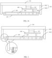
- FIG. 1b shows a schematic structure of a heat dissipation assembly according to an embodiment of this application.
- the heat dissipation assembly provided in this embodiment of this application includes a liquid cold plate 101, a temperature equalization plate 104, and a thermally conductive assembly 102.
- one side of the temperature equalization plate 104 is attached to a heat emitting device 105 on a main board 103.
- the temperature equalization plate 104 may be a thin copper plate with good thermal conductivity, a thin aluminum plate welded with a heat pipe, a thin flat heat pipe, a graphene sheet, or the like. This is not limited in this application.
- the temperature equalization plate 104 may include two sides, and one of the two sides is attached to the heat emitting device 105 on the main board 103.
- the main board 103 may be a PCB board, one or more heat emitting devices 105 may be disposed on the main board 103, and the heat emitting device 105 may be a device, for example, an SOC, a local area network switch LAN SW, or a microcontroller unit (microcontroller unit, MCU).
- the heat emitting device 105 may be a device, for example, an SOC, a local area network switch LAN SW, or a microcontroller unit (microcontroller unit, MCU).
- one side of the temperature equalization plate 104 is attached to the heat emitting device 105 on the main board 103. This is equivalent to that one side of the heat emitting device 105 is fastened on the main board 103, and the other side of the heat emitting device 105 is attached to the temperature equalization plate 104. It should be understood that one side of the temperature equalization plate 104 may directly contact and may be attached to the heat emitting device 105 on the main board 103, or may be indirectly attached to the heat emitting device 105 by using some thermally conductive materials, provided that heat generated by the heat emitting device 105 can be effectively transferred to the temperature equalization plate 104. An attachment manner between the heat emitting device 105 and the temperature equalization plate 104 is not limited in this embodiment.
- a central area of the temperature equalization plate 104 is attached to the heat emitting device 105 on the main board 103, and an edge area of the temperature equalization plate 104 extends to the main board 103 and is fastened on the main board 103.
- the temperature equalization plate 104 is of a "cover-shaped" structure.
- the central area of the temperature equalization plate 104 protrudes in a direction away from the main board to form a hollowed area.
- An inner wall of the hollowed area may be attached to the heat emitting device 105, and the edge area of the temperature equalization plate 104 is fastened to the main board 103, so that heat on the main board 103 can be transferred to the temperature equalization plate 104.
- the "central area” and the "edge area” are relative position expressions, and are not absolute position limitations. In other words, the central area of the temperature equalization plate 104 is closer to a center of the temperature equalization plate 104 relative to the edge area.
- a non-edge area of the temperature equalization plate 104 may alternatively be fastened to the main board 103, provided that it can be ensured that the temperature equalization plate 104 is fastened to the main board 103, and an area for the heat emitting device 105 can be reserved between the temperature equalization plate 104 and the main board 103.
- a fastening manner between the temperature equalization plate 104 and the main board 103 is not limited in this application.
- the liquid cold plate 101 is disposed on a side that is of the temperature equalization plate 104 and that is away from the main board 103.
- the liquid cold plate 101 may be of a structure that has thermal conduction and heat dissipation functions.
- the liquid cold plate 101 is a metal plate.
- the liquid cold plate 101 is an aluminum alloy material or a steel plate.
- the liquid cold plate 101 may alternatively be another thermally conductive material, for example, a ceramic plate or plastic having a thermal conduction capability.
- the liquid cold plate 101 may include a pipeline, and the pipeline may be filled with liquid, so that heat is removed through liquid flowing.
- the liquid may be water or another refrigerant (for example, freon R22).
- the liquid cold plate 101 may be connected to the temperature equalization plate 104 by using the thermally conductive assembly 102, so that the heat generated by the heat emitting device 105 is transferred to the liquid cold plate 101 by using the temperature equalization plate 104 and the thermally conductive assembly 102.
- one end of the thermally conductive assembly 102 is fastened to the liquid cold plate 101, and the other end of the thermally conductive assembly 102 extends to the temperature equalization plate 104 and is connected to the temperature equalization plate 104.
- FIG. 2 shows a schematic structure of a heat dissipation assembly according to an embodiment of this application.
- the thermally conductive assembly 102 may include a thermally conductive assembly body 1021 and a boss 1022, where one end of the thermally conductive assembly body 1021 is fastened to the liquid cold plate 101, the other end of the thermally conductive assembly 102 extends to the temperature equalization plate 104, and the boss 1022 disposed at the other end of the thermally conductive assembly 102 is connected to the temperature equalization plate 104.
- FIG. 1 shows a schematic structure of a heat dissipation assembly according to an embodiment of this application.
- the thermally conductive assembly 102 may include a thermally conductive assembly body 1021 and a boss 1022, where one end of the thermally conductive assembly body 1021 is fastened to the liquid cold plate 101, the other end of the thermally conductive assembly 102 extends to the temperature equalization plate 104, and the boss 1022 disposed at the other end of the thermally conductive assembly
- both the temperature equalization plate 104 and the main board 103 may be fastened on the boss 1022 of the thermally conductive assembly 102 by using screws, so that the temperature equalization plate 104 tightly contacts the boss 1022.
- copper exposure processing may be performed on a part that is of the main board 103 and that contacts the temperature equalization plate 104, so that the heat on the main board 103 can be transferred to the boss 1022 on the liquid cold plate 101 by using the temperature equalization plate 104, heat transfer is implemented, and a temperature of the main board 103 is reduced.
- the temperature equalization plate 104 can collect the heat of the heat emitting device 105 on the main board 103 and transfer the heat to the liquid cold plate 101, to dissipate the heat from the heat emitting device 105.
- the PCB board 106 is fastened between the temperature equalization plate 104 and the liquid cold plate 101, a connector 108 is fastened on the PCB board 106, one end of the connector 108 is connected to the PCB board 106, the connector 108 passes through the temperature equalization plate 104, and the other end of the connector 108 extends to the main board 103 and is fastened on the main board 103.
- An SOC 107 is arranged on the PCB board 106.
- the SOC 107 may be an AI chip.
- the PCB board 106 arranged with the AI chip may be fastened on the main board 103.
- the liquid cold plate 101 is disposed between the PCB board 106 arranged with the Al chip and the main board 103 to dissipate heat from the PCB board 106 arranged with the AI chip and the heat emitting device 105 on the main board 103.
- the PCB board 106 arranged with the AI chip is connected to the main board 103 by using the connector 108, the connector 108 affects a structure of the liquid cold plate 101, and a distance between the PCB board 106 arranged with the AI chip and the main board 103 is excessively small.
- the liquid cold plate 101 is disposed on a side that is of the PCB board 106 and that is away from the main board 103, the connector 108 passes through only the temperature equalization plate 104 between the main board 103 and the PCB board 106 without passing through the liquid cold plate 101. Because the temperature equalization plate 104 conducts heat by using metal and does not have a runner inside, a problem that a heat dissipation capability is significantly degraded because a runner is interrupted does not exists.
- the SOC 107 is arranged on a side that is of the PCB board 106 and that faces the liquid cold plate 101, and the SOC 107 is attached to the liquid cold plate 101, to ensure heat dissipation of the SOC 107 on the PCB board 106.
- heat generated by the SOC 107 on the PCB board 106 or another heat emitting device 105 can be directly transferred to the liquid cold plate 101.
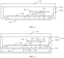
- FIG. 3 shows a schematic structure of a heat dissipation assembly according to an embodiment of this application.
- the SOC 107 is arranged on a side that is of the PCB board 106 and that faces the temperature equalization plate 104, and the SOC 107 is attached to the temperature equalization plate 104.
- heat generated by the SOC 107 on the PCB board 106 or another heat emitting device 105 can be transferred to the temperature equalization plate 104, and be further transferred to the liquid cold plate 101 by using the temperature equalization plate 104 and the thermally conductive assembly 102.
- a heat emitting device 109 may be further arranged on a side that is of the main board and that is away from the temperature equalization plate, a bottom housing may be further disposed on the side that is of the main board and that is away from the temperature equalization plate, and the heat emitting device 109 may be in a thermally conductive contact with the bottom housing 110.
- the liquid cold plate 101, the thermally conductive assembly 102, and the bottom housing may be fastened to be used as a housing of a vehicle-mounted computing apparatus.
- the heat dissipation assembly in this application may be used in the vehicle-mounted computing apparatus, and the heat dissipation assembly can provide a heat dissipation function for a PCB board in the vehicle-mounted computing apparatus and a heat emitting device on the PCB board.
- An embodiment of this application provides a heat dissipation assembly, including a liquid cold plate 101, a temperature equalization plate 104, and a thermally conductive assembly 102, where one side of the temperature equalization plate 104 is attached to a heat emitting device 105 on a main board 103; the liquid cold plate 101 is disposed on a side that is of the temperature equalization plate 104 and that is away from the main board 103; and the liquid cold plate 101 is connected to the temperature equalization plate 104 by using the thermally conductive assembly 102, so that heat generated by the heat emitting device 105 is transferred to the liquid cold plate 101 by using the temperature equalization plate 104 and the thermally conductive assembly 102.
- the temperature equalization plate 104 is added to the main board 103, and the liquid cold plate 101 is disposed on the side that is of the temperature equalization plate 104 and that is away from the main board 103.
- the temperature equalization plate 104 transfers the heat of the heat emitting device 105 on the main board 103 to the liquid cold plate 101.
- a PCB board 106 may be disposed between the temperature equalization plate 104 and the liquid cold plate 101, so that a runner in the liquid cold plate 101 is not interrupted by a connector 108 between the PCB board 106 and the main board 103, thereby improving heat dissipation performance of the liquid cold plate 101.
- connection relationships between modules indicate that the modules have communication connections with each other, and may be specifically implemented as one or more communication buses or signal cables.
- this application may be implemented by software in addition to necessary universal hardware, or by dedicated hardware, including a dedicated integrated circuit, a dedicated CPU, a dedicated memory, a dedicated component, and the like.
- dedicated hardware including a dedicated integrated circuit, a dedicated CPU, a dedicated memory, a dedicated component, and the like.
- any function that can be performed by a computer program can be easily implemented by using corresponding hardware.
- a specific hardware structure used to achieve a same function may be in various forms, for example, in a form of an analog circuit, a digital circuit, or a dedicated circuit.
- software program implementation is a better implementation in most cases.
- the technical solutions in this application may be essentially or a part that contributes to the conventional technology may be reflected in a form of a software product.
- the computer software product is stored in a readable storage medium, for example, a floppy disk, a USB flash drive, a removable hard disk, a ROM, a RAM, a disk drive, or an optical disk of a computer, and includes some instructions used to enable a computer device (which may be a personal computer, a training device, a network device, or the like) to perform the method in embodiments of this application.
- All or some of the foregoing embodiments may be implemented by using software, hardware, firmware, or any combination thereof.
- software is used to implement the embodiments, all or a part of the embodiments may be implemented in a form of a computer program product.
- the computer program product includes one or more computer instructions.
- the computer may be a general-purpose computer, a dedicated computer, a computer network, or another programmable apparatus.
- the computer instructions may be stored in a computer-readable storage medium or may be transmitted from a computer-readable storage medium to another computer-readable storage medium.
- the computer instructions may be transmitted from a website, computer, server, or data center to another website, computer, server, or data center in a wired (for example, a coaxial cable, an optical fiber, or a digital subscriber line (DSL)) or wireless (for example, infrared, radio, or microwave) manner.
- a wired for example, a coaxial cable, an optical fiber, or a digital subscriber line (DSL)
- wireless for example, infrared, radio, or microwave
- the computer-readable storage medium may be any usable medium accessible by the computer, or a data storage device, such as a server or a data center, integrating one or more usable media.
- the usable medium may be a magnetic medium (for example, a floppy disk, a hard disk, or a magnetic tape), an optical medium (for example, a DVD), a semiconductor medium (for example, a solid state disk (Solid State Disk, SSD)), or the like.
Landscapes
- Engineering & Computer Science (AREA)
- Microelectronics & Electronic Packaging (AREA)
- Physics & Mathematics (AREA)
- Thermal Sciences (AREA)
- Mechanical Engineering (AREA)
- Cooling Or The Like Of Electrical Apparatus (AREA)
Applications Claiming Priority (2)
| Application Number | Priority Date | Filing Date | Title |
|---|---|---|---|
| CN202010901484.2A CN114126328B (zh) | 2020-08-31 | 2020-08-31 | 一种散热组件及汽车 |
| PCT/CN2021/105891 WO2022042092A1 (zh) | 2020-08-31 | 2021-07-13 | 一种散热组件及汽车 |
Publications (2)
| Publication Number | Publication Date |
|---|---|
| EP4199669A1 true EP4199669A1 (de) | 2023-06-21 |
| EP4199669A4 EP4199669A4 (de) | 2024-01-24 |
Family
ID=80354499
Family Applications (1)
| Application Number | Title | Priority Date | Filing Date |
|---|---|---|---|
| EP21859932.2A Pending EP4199669A4 (de) | 2020-08-31 | 2021-07-13 | Wärmeableitungsanordnung und kraftfahrzeug |
Country Status (4)
| Country | Link |
|---|---|
| EP (1) | EP4199669A4 (de) |
| KR (1) | KR102851520B1 (de) |
| CN (3) | CN116669282A (de) |
| WO (1) | WO2022042092A1 (de) |
Families Citing this family (1)
| Publication number | Priority date | Publication date | Assignee | Title |
|---|---|---|---|---|
| CN115734536A (zh) * | 2022-11-04 | 2023-03-03 | 蔚来汽车科技(安徽)有限公司 | 控制器及包括该控制器的车辆 |
Family Cites Families (10)
| Publication number | Priority date | Publication date | Assignee | Title |
|---|---|---|---|---|
| US7336490B2 (en) * | 2004-11-24 | 2008-02-26 | Hewlett-Packard Development Company, L.P. | Multi-chip module with power system |
| CN101754643B (zh) * | 2008-12-10 | 2012-08-08 | 华硕电脑股份有限公司 | 电子装置及其散热模块 |
| CA2682442C (en) * | 2009-10-14 | 2017-09-12 | Claude Pinet | High efficiency thermoelectric cooling system and method of operation |
| US9123686B2 (en) * | 2013-04-12 | 2015-09-01 | Western Digital Technologies, Inc. | Thermal management for solid-state drive |
| CN206294475U (zh) * | 2016-12-30 | 2017-06-30 | 潍坊歌尔电子有限公司 | 电子产品散热结构及小型化电子产品 |
| CN106714517B (zh) * | 2016-12-30 | 2018-08-17 | 上海航天科工电器研究院有限公司 | 一种多点温度监测的液冷式板卡模块 |
| KR102391167B1 (ko) * | 2017-06-08 | 2022-04-27 | 주식회사 만도 | 방열 어셈블리 |
| US10481651B2 (en) * | 2017-12-07 | 2019-11-19 | Toyota Motor Engineering & Manufacturing North America, Inc. | Integrated PCU and GPU cooling system |
| CN208314701U (zh) * | 2018-05-11 | 2019-01-01 | 深圳市七彩虹禹贡科技发展有限公司 | 一种水冷风冷均热一体化的显卡散热装置 |
| CN110557931B (zh) * | 2019-08-30 | 2020-12-08 | 华为技术有限公司 | 车载设备和车辆 |
-
2020
- 2020-08-31 CN CN202310524550.2A patent/CN116669282A/zh active Pending
- 2020-08-31 CN CN202010901484.2A patent/CN114126328B/zh active Active
-
2021
- 2021-07-13 KR KR1020237010896A patent/KR102851520B1/ko active Active
- 2021-07-13 CN CN202190000672.6U patent/CN221178222U/zh active Active
- 2021-07-13 EP EP21859932.2A patent/EP4199669A4/de active Pending
- 2021-07-13 WO PCT/CN2021/105891 patent/WO2022042092A1/zh not_active Ceased
Also Published As
| Publication number | Publication date |
|---|---|
| WO2022042092A1 (zh) | 2022-03-03 |
| CN114126328B (zh) | 2023-06-09 |
| KR20230056783A (ko) | 2023-04-27 |
| KR102851520B1 (ko) | 2025-08-27 |
| CN114126328A (zh) | 2022-03-01 |
| EP4199669A4 (de) | 2024-01-24 |
| CN221178222U (zh) | 2024-06-18 |
| CN116669282A (zh) | 2023-08-29 |
Similar Documents
| Publication | Publication Date | Title |
|---|---|---|
| US12575071B2 (en) | Computing apparatus and vehicle | |
| EP3839686B1 (de) | Fahrzeugmontierte steuereinheit sowie fpga-basiertes verfahren und vorrichtung zum automatischen fahren eines fahrzeugs | |
| EP4228382B1 (de) | Wärmeableitungsvorrichtung und fahrzeug | |
| US12007818B2 (en) | Floating heat spreader for processing assembly | |
| EP4199669A1 (de) | Wärmeableitungsanordnung und kraftfahrzeug | |
| CN111818189A (zh) | 一种车路协同控制系统、方法及介质 | |
| CN116714537A (zh) | 一种中央域控制器及车辆 | |
| EP4199668A1 (de) | Wärmeableitungsanordnung und kraftfahrzeug | |
| US20250331133A1 (en) | Heat Dissipation Apparatus, Electronic Device, and Vehicle | |
| CN119749217B (zh) | 车辆热管理方法、装置及设备 | |
| US11629920B2 (en) | Structural mount with integrated cooling for autonomous vehicle sensors | |
| CN117769199A (zh) | 数据处理装置和车辆 | |
| CN216596516U (zh) | 一种用于智能船的电控主机驱动器 | |
| CN223843990U (zh) | 一种域控制器及车辆 | |
| CN215341065U (zh) | 一种感知系统通用接口集成装置 | |
| US20250261299A1 (en) | Multi-material three-dimensional thermal conductive traces | |
| EP4596286A1 (de) | Elektronische steuereinheit, steuersystem und endgerät | |
| WO2025247096A1 (zh) | 控制模块和电子设备 | |
| CN210941734U (zh) | 一种全自动泊车系统的控制器及车辆 | |
| CN106004731B (zh) | 散热良好的新能源汽车整车控制器 | |
| WO2026045651A1 (zh) | 数据采集电路、数据采集装置和汽车 | |
| CN119882868A (zh) | 控制器的散热方法、装置、设备及介质 | |
| CN117769200A (zh) | 散热装置、散热组件和车辆 | |
| CN118171454A (zh) | 一种散热结构设计方法、装置、可读存储介质及终端设备 | |
| CN115794430A (zh) | 用于多系统间通信的方法、服务系统、设备和存储介质 |
Legal Events
| Date | Code | Title | Description |
|---|---|---|---|
| STAA | Information on the status of an ep patent application or granted ep patent |
Free format text: STATUS: THE INTERNATIONAL PUBLICATION HAS BEEN MADE |
|
| PUAI | Public reference made under article 153(3) epc to a published international application that has entered the european phase |
Free format text: ORIGINAL CODE: 0009012 |
|
| STAA | Information on the status of an ep patent application or granted ep patent |
Free format text: STATUS: REQUEST FOR EXAMINATION WAS MADE |
|
| 17P | Request for examination filed |
Effective date: 20230314 |
|
| AK | Designated contracting states |
Kind code of ref document: A1 Designated state(s): AL AT BE BG CH CY CZ DE DK EE ES FI FR GB GR HR HU IE IS IT LI LT LU LV MC MK MT NL NO PL PT RO RS SE SI SK SM TR |
|
| DAV | Request for validation of the european patent (deleted) | ||
| DAX | Request for extension of the european patent (deleted) | ||
| A4 | Supplementary search report drawn up and despatched |
Effective date: 20240104 |
|
| RIC1 | Information provided on ipc code assigned before grant |
Ipc: H05K 7/20 20060101AFI20231221BHEP |
|
| RAP1 | Party data changed (applicant data changed or rights of an application transferred) |
Owner name: SHENZHEN YINWANG INTELLIGENTTECHNOLOGIES CO., LTD. |