EP4200101B1 - Procédé de production d'au moins une partie de pièce à usiner et d'une pièce à usiner résiduelle à partir d'une pièce à usiner - Google Patents
Procédé de production d'au moins une partie de pièce à usiner et d'une pièce à usiner résiduelle à partir d'une pièce à usiner Download PDFInfo
- Publication number
- EP4200101B1 EP4200101B1 EP20767480.5A EP20767480A EP4200101B1 EP 4200101 B1 EP4200101 B1 EP 4200101B1 EP 20767480 A EP20767480 A EP 20767480A EP 4200101 B1 EP4200101 B1 EP 4200101B1
- Authority
- EP
- European Patent Office
- Prior art keywords
- workpiece
- laser beam
- cutting
- modification
- line
- Prior art date
- Legal status (The legal status is an assumption and is not a legal conclusion. Google has not performed a legal analysis and makes no representation as to the accuracy of the status listed.)
- Active
Links
Images




Classifications
-
- B—PERFORMING OPERATIONS; TRANSPORTING
- B23—MACHINE TOOLS; METAL-WORKING NOT OTHERWISE PROVIDED FOR
- B23K—SOLDERING OR UNSOLDERING; WELDING; CLADDING OR PLATING BY SOLDERING OR WELDING; CUTTING BY APPLYING HEAT LOCALLY, e.g. FLAME CUTTING; WORKING BY LASER BEAM
- B23K26/00—Working by laser beam, e.g. welding, cutting or boring
- B23K26/36—Removing material
- B23K26/38—Removing material by boring or cutting
-
- B—PERFORMING OPERATIONS; TRANSPORTING
- B23—MACHINE TOOLS; METAL-WORKING NOT OTHERWISE PROVIDED FOR
- B23K—SOLDERING OR UNSOLDERING; WELDING; CLADDING OR PLATING BY SOLDERING OR WELDING; CUTTING BY APPLYING HEAT LOCALLY, e.g. FLAME CUTTING; WORKING BY LASER BEAM
- B23K26/00—Working by laser beam, e.g. welding, cutting or boring
- B23K26/02—Positioning or observing the workpiece, e.g. with respect to the point of impact; Aligning, aiming or focusing the laser beam
- B23K26/06—Shaping the laser beam, e.g. by masks or multi-focusing
- B23K26/0604—Shaping the laser beam, e.g. by masks or multi-focusing by a combination of beams
-
- B—PERFORMING OPERATIONS; TRANSPORTING
- B23—MACHINE TOOLS; METAL-WORKING NOT OTHERWISE PROVIDED FOR
- B23K—SOLDERING OR UNSOLDERING; WELDING; CLADDING OR PLATING BY SOLDERING OR WELDING; CUTTING BY APPLYING HEAT LOCALLY, e.g. FLAME CUTTING; WORKING BY LASER BEAM
- B23K26/00—Working by laser beam, e.g. welding, cutting or boring
- B23K26/60—Preliminary treatment
Definitions
- the invention lies in the technical field of the production of metallic workpiece parts and relates to a method for laser processing a plate-shaped or tubular workpiece, in which a separating processing of the workpiece to produce a cutting gap and a non-separating and at the same time non-joining modification of the workpiece is carried out by a laser beam.
- the cut edges of the workpiece parts may require complex mechanical post-processing. It may be desirable to round off sharp cut edges or to provide them with a chamfer, and to remove burrs, particularly those caused by slag or melt residues formed during laser processing.
- the object of the present invention is to further develop conventional methods in which workpiece parts are cut out of a plate- or tubular workpiece by means of a laser beam in such a way that the production of workpiece parts with chamfered or rounded cutting edges, as well as with removed burrs, can be carried out in an automated manner faster, more cost-effectively and with high quality.
- This object is achieved by a two-stage process for producing a workpiece part and a remaining workpiece from the workpiece by means of a laser beam and a process gas for expelling molten workpiece material, which jointly exit from a nozzle of a laser processing head.
- the term "workpiece” refers to a plate- or tubular, typically metallic component from which at least one workpiece part (good part) is to be produced.
- the plate-shaped workpiece is typically planar or flat.
- a non-separating and at the same time non-joining modification of the workpiece is also carried out using a laser beam.
- the laser beam can be used either for separating machining or alternatively for non-separating and at the same time non-joining machining of the workpiece.
- the energy density of the laser beam indicates the energy of the laser beam in relation to the surface of the workpiece irradiated by the laser beam, for example measured in J/mm 2 .
- Relevant for the creation of a cutting gap or a non-separating or non-joining modification of the workpiece is the energy density in relation to the time interval in which the irradiated surface of the workpiece is irradiated, for example measured in J/(mm 2 xs), here and below referred to as "power density”. If the power density absorbed by the workpiece is essential, the power density can also be understood as the power density absorbed by the workpiece.
- the laser processing of a plate or tubular workpiece comprises the creation of a cutting gap that cuts through the workpiece or one or more sections of the cutting gap along a cutting line of the workpiece part.
- the cutting line corresponds to a contour (ie outline) of the workpiece part to be produced from the workpiece.
- the laser processing head is moved over the workpiece, with the laser beam being guided along the cutting line.
- the A cutting line is therefore a predetermined or predeterminable (imaginary) line or path along which the laser beam or laser processing head is guided to cut out the part of the workpiece contoured by the cutting line.
- the laser beam has a power density that is dimensioned such that the workpiece is (completely) severed.
- the laser beam interacts with a process gas (cutting gas) directed at the cutting line.
- the power density can take on different values, so it does not have to be constant.
- the reference system is always stationary to the workpiece, so that the laser processing head is considered to be moving and the workpiece is considered to be stationary. From a local perspective, however, it is irrelevant whether the laser processing head or the workpiece or both are moved. In this respect, it would be equally possible for the workpiece to be moved as an alternative to the moving laser processing head, or for both the laser processing head and the workpiece to be moved.
- the workpiece part is partially or completely cut out along its contour, i.e. the cutting gap always forms a contour.
- the term "cutting gap" in the sense of the present invention does not include sections of the cutting gap that do not form a contour and do not extend along the contour of the workpiece part. For example, when cutting out a workpiece part, the workpiece is often pierced away from the contour and the laser beam is first moved a short distance towards the contour-forming cutting line of the workpiece part.
- Cutting a workpiece part free from the workpiece i.e. completely cutting out the workpiece part from the workpiece so that it can be detached or removed from the workpiece, is done by creating a closed cutting gap along the cutting line of the workpiece part.
- the remaining workpiece if at least one workpiece part to be cut out is at least notionally removed, is referred to as a "residual workpiece".
- a modification of the workpiece only takes place if the workpiece part is partially, ie not completely, cut out or, alternatively, no separating processing has yet taken place on the workpiece part.
- the cutting gap is always limited by two opposing cutting edges, i.e. a cutting edge on the workpiece part side and a cutting edge on the remaining workpiece side.
- a partially cut-out workpiece part is still firmly connected to the rest of the workpiece (i.e. remaining workpiece), i.e. the partially cut-out workpiece part is still an integral part of the workpiece.
- the connection of a partially cut-out workpiece part to the remaining workpiece is sufficiently rigid so that a change in position of the partially cut-out workpiece part relative to the workpiece (remaining workpiece) does not occur when the workpiece is modified or any change in position that may occur is negligible and does not lead to any change in the result of a modification of the workpiece according to the invention that can be reasonably taken into account.
- the laser beam emerges together with the process gas from a nozzle, which is part of a laser processing head.
- the nozzle is opposite the top of the workpiece.
- the workpiece in particular a plate-shaped workpiece, rests on a workpiece support with the bottom of the workpiece.
- the workpiece On the top of the workpiece, the workpiece has a (top-side) workpiece surface.
- the workpiece surface is flat.
- the "workpiece surface" is understood to mean the top-side workpiece surface that is opposite the nozzle or faces the nozzle.
- the laser beam is aligned perpendicular to the workpiece surface.
- the gas pressure of the process gas in step b) is less than 7 bar and in particular between 3 bar and 6 bar. This gas pressure (boiler pressure) applies within the laser processing head before the process gas exits the nozzle.
- step a) is carried out before step b).
- Steps a) and b) can each be carried out several times in succession without the other step being carried out between two steps with the same name.
- a plurality of steps a) are carried out before one or more steps b).
- a plurality of steps a) and a plurality of steps b) are carried out in alternating sequence, wherein after a step with one name (i.e. step a) or b)), a step with the other name (i.e. step b) or a)) is carried out.
- the various embodiments of the method according to the invention can be combined with one another.
- step a) can be executed once or more than once, followed by step b) being executed once or more than once.
- step a) is carried out before step b), wherein in step a) a section of the cutting gap is created along the cutting line. No closed cutting gap is created. Rather, the workpiece part remains connected to the remaining workpiece. Then in step b) at least a part of at least one of the cutting edges on the workpiece part or on the remaining workpiece is provided with a chamfer or a rounding.
- the workpiece part is still connected to the remaining workpiece via one or more webs, in particular microjoints or nanojoints.
- a "web” is a web extending along the cutting line
- a "microjoint” is understood to be a connection of workpiece material extending between the workpiece part and the remaining workpiece, with the web interrupting the cutting gap.
- a "microjoint” is a web with a relatively small dimension along the cutting line, which according to the invention is preferably in the range from 1/10 mm to 2 mm, particularly preferably in the range from 1/10 mm to 1 mm.
- a microjoint has a height which corresponds to the height or thickness of the workpiece (ie dimension perpendicular to the workpiece surface).
- a “nanojoint” is a microjoint whose height is reduced in relation to the thickness of the workpiece, with the height of a nanojoint preferably being a maximum of half the thickness of the workpiece according to the invention.
- Microjoints and nanojoints are well known to the person skilled in the art from the practice of manufacturing sheet metal workpiece parts by laser processing and from the patent literature, so that there is no need to go into them in more detail here. With regard to nanojoints, reference is only made to the international patent application WO 2019025327 A2 referred to.
- step a) or carrying out step a) multiple times at least a part of at least one of the cut edges formed on the workpiece part or on the remaining workpiece is provided with a chamfer or rounding, while the workpiece part is still connected to the remaining workpiece. Only then is the workpiece part cut free, for example by the laser beam or manually, for example by breaking the workpiece part out of the workpiece.
- the cutting line and the modification line run parallel, with the modification line having a lateral offset perpendicular to the cutting line. The cutting line and the modification line are therefore not identical in this embodiment of the method, i.e. they do not have an identical course.
- the at least one web in particular a microjoint or nanojoint, is also modified, i.e. provided with a chamfer or a rounding.
- a web between the workpiece part and the remaining workpiece only slightly disturbs the gas dynamics of the process gas if the web is sufficiently small along the cutting line. This applies in particular if the web is designed as a microjoint and has a dimension along the cutting line in the range of 1/10 mm to 2 mm, particularly preferably in the range of 1/10 mm to 1 mm.
- the inventors have recognized that it is advantageous for the production of a rounded or chamfered cutting edge on a workpiece part if the workpiece part is connected to the rest of the workpiece, i.e. there is still workpiece material on both sides of the cutting gap.
- the workpiece part is in It is fixed in its position and cannot slip or tilt, so that the laser beam can be positioned exactly to the cutting edge when creating the bevel or rounding.
- the melt that is created when creating the bevel or rounding flows into the cutting gap and can be removed from there - especially when using oxygen as the process gas - more easily than from the top of the bevel.
- the pressure of the process gas before it exits the nozzle must not exceed 7 bar in order to avoid excessive splashes of material on the workpiece surface.
- the gas pressure is preferably between 3 bar and 6 bar, which on the one hand ensures that the melt is removed well and on the other hand that splashes of material can be reliably and safely avoided.
- the distance between the nozzle from which the laser beam emerges and the workpiece surface is greater in step b) than in step a) in order to achieve a less concentrated, "softer" effect of the process gas on the workpiece surface.
- the greater distance of the nozzle from the workpiece surface enables a larger beam spot on the workpiece. This enables the production of wider bevels in particular.
- an advantageous distance between the nozzle and the workpiece or the workpiece surface according to the invention depends on the process gas used.
- the distance between the nozzle and the workpiece surface in step b) for producing bevels with oxygen as the process gas is preferably at least 9 mm, better at least 20 mm and particularly preferably at least 35 mm.
- the distance between the nozzle and the workpiece in step b) is preferably at least 1 mm, better at least 6 mm and particularly preferably at least 9 mm.
- oxygen is preferably used as the process gas in step b) for a workpiece made of structural steel.
- the melt formed is advantageously completely oxidized in the cutting gap and can therefore be easily removed from the workpiece.
- the power density or the energy per unit length of the laser beam on the workpiece in step b) is lower than in step a), which can preferably be achieved by reducing the power of the laser beam, increasing the feed rate of the laser processing head containing the nozzle, defocusing the laser beam by changing the focus position relative to the workpiece and/or by changing the beam diameter on the workpiece surface.
- the beam diameter perpendicular to the beam axis at a particular point on the laser beam determines the power density of the laser beam at that point on the laser beam.
- the beam diameter is the diameter of the circular cross-sectional area of the laser beam perpendicular to the beam axis.
- the larger the beam diameter, the smaller the power density, and vice versa In the area between the focusing lens or focusing mirror and the focus, the laser beam converges; after the focus, the laser beam diverges. Viewed in the direction of beam propagation, the power density increases in the convergent area with increasing distance from the focusing lens or focusing mirror, has its highest value at the focus, and decreases in the divergent area with increasing distance from the focus.
- the power density on the workpiece therefore depends on the size of the irradiated area (beam spot on the workpiece), corresponding to the beam diameter at the point where at which the laser beam hits the workpiece.
- the beam diameter on the workpiece depends on the focus position of the laser beam.
- the term "focus position" refers to the position of the focus relative to the workpiece, in particular relative to the plane of the workpiece surface.
- the focus position is the vertical (shortest) distance of the focus from the workpiece surface.
- the beam diameter on the workpiece can be changed by changing the focus position. If the workpiece is in the divergent area of the beam cone (focus above the workpiece surface), the beam diameter on the workpiece can be increased by increasing the distance between the focus and the workpiece, and vice versa.
- the power density on the workpiece can be specifically changed by changing the beam diameter on the workpiece.
- the beam intensity outside the focus is not constant in relation to the cross-section.
- the power intensity is a Gaussian profile. In any case, the power density is relatively low towards the edge, especially outside the focus.
- the focus of the laser beam is on or above the workpiece surface in step b).
- the average laser power in step b) is preferably less than 3500 W
- the focus diameter of the laser beam is preferably at least 150 ⁇ m and/or the feed rate is preferably at least 1 m/min.
- the focus diameter for a focus position on the workpiece surface is preferably more than 250 ⁇ m.
- the cutting line and modification line are selected so that they run parallel and form a lateral offset perpendicular to the cutting line.
- the offset between the cutting line and the modification line is preferably at least 0.2 mm and not more than 1.5 mm, whereby a desired modification of the workpiece can be produced efficiently and safely.
- the method is advantageously carried out in such a way that in order to produce a chamfer or rounding on the cutting edge, only a single action of the laser beam on the workpiece is necessary and no multiple movements of the laser beam along the modification line are carried out.
- the laser beam is guided along the modification line in step b).
- the laser beam is always moved in a straight line along the modification line in step b).
- the path of the laser beam along the modification line is identical to the modification line.
- a chamfer or rounding on an already formed cutting edge can thus be created by a straight line movement of the laser beam along the modification line, which enables a particularly fast modification of the workpiece.
- a depression on the workpiece surface can be created particularly quickly in a simple manner.
- the laser beam in step b) transversely to the modification line.
- the movement of the laser beam in step b) along the modification line in addition to movement components along the modification line, also has movement components transversely (i.e. perpendicularly) to the modification line, so that a larger area of the workpiece is covered by the laser beam.
- the laser beam performs a meandering back and forth movement along the modification line. During its movement along the modification line, the laser beam is guided away from the modification line several times and then back to it again.
- the laser beam is guided along closed path sections, which are preferably arranged in rows along the modification line.
- Each closed path section is by crossing the previously traveled path of the laser beam.
- the closed path sections are circular closed path sections (ie circles) or ellipses, which are preferably arranged in rows along the modification line.
- bevels with greater bevel depths and/or bevel widths can be produced along the modification line.
- a movement component of the laser beam transverse to the modification line advantageously has an extension of at least 0.5 mm and at most 5 mm.
- the laser beam When moving along closed path sections, in particular along circles or ellipses, the laser beam preferably has an overlap along the modification line in the range of 0.5 mm to 1 mm.
- An overlap of the closed path sections (e.g. circles) along the modification line is advantageously 0.5 mm to 1 mm.
- a further process step c) is carried out, in which slag/melt formed during steps a) and b) is removed from the workpiece.
- Step c) comprises the removal of slag from at least one of the cutting edges or bevel edges on the workpiece part or remaining workpiece, wherein the laser beam is moved along the cutting line or a line laterally offset therefrom, and/or the removal of slag from a bevel or a fillet, wherein the laser beam is moved along the modification line or a line laterally offset therefrom.
- the power density or the energy per unit length of the laser beam on the workpiece is lower in step c) than in step a).
- the laser power when removing the slag/melt is significantly lower than in the cutting process, with the average power preferably being less than 1000 W.
- the distance between the nozzle and the workpiece surface is preferably greater in step c) than in step a) and is preferably at least 5 mm, preferably between 6 mm and 12 mm.
- the gas pressure of the process gas in the laser processing head is preferably lower in step c) than in step a) and is preferably less than 7 bar, preferably between 0.7 bar and 6 bar.
- the focus diameter of the laser beam is preferably at least 150 ⁇ m.
- the laser beam used in step c) simultaneously cuts the workpiece part free from the remaining workpiece, with the laser power of the laser beam for this purpose preferably being at least 500 W.
- the workpiece part is connected to the remaining workpiece by one or more nanojoints (i.e. microjoints with a reduced height), which can be easily severed by the laser beam used to remove the slag.
- one or more sections of the cutting gap are created.
- adjacent sections of the cutting gap border on a web, in particular a microjoint or nanojoint.
- the cutting gap it is also possible for the cutting gap to be successively extended by the sections.
- the workpiece is modified in any case when the workpiece part has not been cut free or when no separating machining has yet been carried out on the workpiece part.
- the workpiece is modified along the modification line, and the modification of the workpiece takes place in a relatively wide modification zone, particularly when the laser beam is also moved transversely to the modification line. It goes without saying that the modification zone also extends along the modification line.
- the modification of the workpiece can also be carried out in sections, i.e. the modification can be carried out in several sections one after the other, for example separately by machining the workpiece.
- a modification of the workpiece can also be carried out in an area of the workpiece along the modification line that does not have a cutting gap, in particular in the area of one or more webs.
- the laser beam When modifying the workpiece, the laser beam has a power density that is lower than the power density used for cutting the workpiece. This means that if a cutting gap has already been created, when modifying the workpiece the partially cut-out workpiece part is not reconnected to the remaining workpiece across the cutting gap. Likewise, no opening is created in the workpiece when modifying the workpiece.
- At least two sections, preferably several sections, of the cutting gap are produced.
- the separating machining of the workpiece is thus interrupted at least once, with preferably at least one web remaining between the workpiece part and the remaining workpiece.
- a section of the cutting gap produced last preferably has a length measured along the cutting line that is smaller than the respective length of every other previously produced section of the cutting gap. For example, the lengths of the successively produced sections of the cutting gap, viewed from a free cutting point of the workpiece part, do not decrease in the opposite direction to the direction in which the cutting gap is produced.
- this measure can be used in a particularly advantageous manner to ensure that the workpiece can be modified along as large a part of the cutting line as possible.
- An unmodified part of the workpiece, with which the partially cut-out workpiece part is still connected to the workpiece, is thus small in comparison to the modified part.
- the workpiece is also modified along the modification line where there is no cutting gap.
- a modification of the workpiece can take place in an area that contains the workpiece part-side cutting edge and/or the remaining workpiece-side cutting edge of the cutting gap, whereby it is equally possible that the workpiece part-side cutting edge and/or the remaining workpiece-side cutting edge of the cutting gap are not included.
- a first modification of the workpiece takes place in a modification zone that contains the workpiece part-side cutting edge and/or the remaining workpiece-side cutting edge of the cutting gap, and each further modification no longer contains the cutting edges.
- This design is particularly advantageous when creating a chamfer on the cutting gap, whereby in a subsequent modification the laser beam can be moved further into the workpiece part or remaining workpiece in the direction away from the cutting edge, for example in order to widen the chamfer.
- a modification zone of a subsequent modification can at least partially contain a modification zone of a previous modification.
- the direction of movement of the laser beam for modifying the workpiece can correspond to the direction of movement of the laser beam for generating the cutting gap or can be opposite to this.
- the distance of the modification line from the cutting line is a maximum of half the gap width of the cutting gap plus the radius of a beam cone of the laser beam on the workpiece surface.
- the distance of the modification line from the cutting line is also possible for the distance of the modification line from the cutting line to be greater, for example in the case of a multi-stage production of a bevel, in which the modification line in a subsequent modification is arranged further away from the cutting gap than the modification line of a previous modification.
- the modification zone contains at least one cutting edge in a first modification, whereby the modification zone no longer contains the cutting edge in a subsequent modification.
- the laser beam When modifying the workpiece, the laser beam has a power density that is dimensioned such that a non-joining and at the same time non-separating (but possibly remelting) modification of the workpiece is effected. During the modification, a connection is therefore neither created between the partially cut-out workpiece part and the remaining workpiece across the cutting gap, nor is the workpiece severed.
- the influence of the process gas is taken into account here, whereby the power density of the laser beam can also be understood as the power density absorbed by the workpiece.
- a change in the power density or the absorbed power density can be achieved by various measures, in particular by changing the energy of the laser beam, changing the beam focus, changing the distance of the nozzle from the workpiece surface, changing the type and/or parameters of the process gas and the like.
- the measures for changing the power density are well known to those skilled in the art, so there is no need to go into them in more detail here.
- the power density is advantageously changed exclusively by changing the vertical distance of the nozzle from the workpiece surface.
- the power density during a modification of the workpiece is less than 50%, less than 40%, less than 30%, less than 20%, less than 10% or less than 1% of the power density during the cutting process.
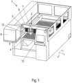
- the laser processing device designated overall by the reference number 1, comprises a laser cutting device 2 with a laser processing head 3, as well as a work table 4 with a flat workpiece support 5 for a workpiece 9 (not shown in Figure 1 , see e.g. Figures 2 to 16 ), for example a flat sheet of metal.
- the workpiece support 5 is spanned by a cross member 6, which is guided so that it can move along a first axial direction (x-direction).
- a guide carriage 7 for the laser processing head 3 is mounted on the cross member 6, which is guided so that it can move on the cross member 6 along a second axial direction (y-direction) perpendicular to the first axial direction.
- the laser processing head 3 can thus be moved in a plane spanned by the two axial directions (x-, y-direction) parallel to and relative to, for example, the horizontal workpiece support 5.
- the laser processing head 3 is also designed to be vertically movable in a third axial direction (z-direction) perpendicular to the first and second axial directions, whereby the distance perpendicular to the workpiece support 5 or workpiece 9 can be changed.
- a third axial direction z-direction
- the z-direction corresponds to the direction of gravity.
- the laser processing head 3 has a nozzle 13 on its side facing the workpiece support 5, which tapers conically towards the workpiece support 5.
- the laser processing head 3 serves to guide a laser beam 16 (see e.g. Figures 2 to 16 ), as well as a process gas jet (not shown in the figures).
- the laser beam 16 is generated by a laser beam source 8 and guided to the laser processing head 3, for example, through a beam guide tube and several deflection mirrors or a fiber optic cable.
- the laser beam 16 can be directed in bundled form (ie focused) onto the workpiece 9 via a focusing lens or adaptive optics. Due to the movability of the laser processing head 3 along the first axial direction (x-direction) and second axial direction (y-direction), any point on the workpiece 9 can be approached with the laser beam 16.
- the workpiece 9 has two opposing workpiece surfaces 17, 20 (see e.g. Figure 23 ), with a first workpiece surface 17 on a workpiece top 35 facing the nozzle 13 and a second workpiece surface 20 on a workpiece bottom 36 facing away from the nozzle 13. Due to the height adjustment of the laser processing head 3 in the z-direction, the (working) distance of the nozzle 13 to the workpiece 9 can be adjusted by changing the distance to the upper workpiece surface 17. The distance of the laser processing head 3 from the upper workpiece surface 17 can be adjusted before, during and after laser processing. The focus position of the laser beam 16 can be adjusted by changing the distance of the Nozzle 13 can be adjusted from the upper workpiece surface 17 and/or via optical elements in the laser processing head 3, for example an adaptive optics.
- a process gas is used to drive the melt out of the cutting kerf.
- the process gas is generated by a gas jet generation device (not shown).
- Helium (He), argon (Ar) or nitrogen (N 2 ) are used as inert working gases, for example.
- Oxygen (O 2 ) is usually used as a reactive working gas.
- the process gas has a predetermined cutting gas pressure (boiler pressure) within the laser processing head 3, exits from the nozzle 13 at this pressure and is guided to the processing point coaxially to the laser beam 16.
- the flat workpiece support 5 consists, for example, of a plurality of support elements with, for example, triangular support point tips, which together define a support plane for the workpiece 9 to be machined.
- the support elements are designed here, for example, as elongated support webs, each of which extends along the y-direction and is arranged next to one another in parallel along the x-direction with, for example, a constant spacing.
- an extraction device by means of which cutting smoke, slag particles and small waste parts generated during laser cutting can be extracted.
- a program-controlled control device 12 serves to control/regulate the method according to the invention for laser processing of the workpiece 9 in the laser processing device 1.
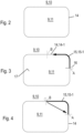
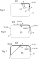
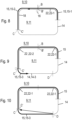
- FIG. 2 to 16 taken, in which exemplary embodiments of the inventive method for laser processing a workpiece 9 according to the invention (ie step a) is carried out before step b)) are illustrated.
- the Figures 2 to 16 correspond in this order to later procedural situations.
- the cutting line 14 is an imaginary line which corresponds to the contour of a workpiece part 11 to be produced from the workpiece 9.
- the contour gives the outer shape of the workpiece part 11 again.
- the workpiece part 11 is to be completely cut out of the plate- or tubular workpiece 9 (not shown in detail), leaving the remaining workpiece 10.
- the workpiece part 11 here has, for example, a rectangular shape with rounded corners, although it is understood that the workpiece part 11 can have any shape.
- FIG 3 the laser beam 16 emerging from the laser processing head 3 is schematically illustrated.
- the laser beam 16 is guided along the cutting line 14, whereby a cutting gap 15 is generated in the workpiece 9 at a corresponding power density on the workpiece 9.
- the laser processing head 3 has been moved to a position above the cutting line 14 in which the laser beam 16 hits a cutting position A of the cutting line 14.
- the laser processing head 3 is moved along the cutting line 14, wherein the laser beam 16 is moved from the cutting position A to a cutting position B.
- a cutting gap 15 solid line
- the cutting gap 15 is produced in sections, whereby a first section 15-1 of the cutting gap 15 is produced first.
- the first section 15-1 of the cutting gap 15 is correspondingly produced in a first section 14-1 of the cutting line 14.
- the laser beam 16 can also penetrate into the workpiece 9 away from the cutting line 14, whereby the cutting gap 15 in the sense of the present invention only extends along the contour (i.e. cutting line 14) of the workpiece part 11.
- FIG 4 a situation is illustrated in which the first section 15-1 of the cutting gap 15 from the cutting position A to the cutting position B has been completely created.
- the separating processing of the workpiece 9 is now interrupted.
- the laser beam 16 is switched off and the laser processing head 3 is moved to a modification position A' near the cutting position A.
- the movement of the laser processing head 3 occurs in a direct line between the cutting position B and the modification position A'.
- the modification position A' lies on a modification line 18 (see Figure 5 ).
- the modification line 18 is offset laterally and arranged equidistant from the cutting line 14.
- the laser processing head 3 is moved along the modification line 18 during the modification of the workpiece 9, whereby the movement of the laser processing head 3 can be straight or non-straight along the modification line 18, as will be explained in more detail below.
- a modification of the workpiece 9 takes place in a modification zone 22, which typically has a wider dimension perpendicular to its extension than the modification line 18, which is not shown in the drawing.
- the modification zone 22 is to be understood as the area of the workpiece 9 that is modified by the laser irradiation.
- the modification zone 22 also extends along the cutting line 14.
- the cutting gap 15 is delimited by two opposing cutting edges 19, 19' (see e.g. Figure 23 ).
- the laser beam 16 is then switched on again and the laser processing head 3 is moved along the modification line 18 (dashed line), wherein the laser beam 16 is moved from the first modification position A' to a second modification position B' near the cutting position B.
- a modification of the workpiece 9 takes place in a first section 22-1 of the modification zone 22.
- Figure 6 a situation is shown in which the workpiece 9 has been modified along the entire first section 15-1 of the cutting gap 15.
- the modified area or the first section 22-1 of the modification zone 22 is schematically illustrated with a solid line. Analogous to the section-by-section creation of the cutting gap 15, the modification zone 22 is also created section-by-section.
- FIG 7 a situation is illustrated in which a further or second section 15-2 of the cutting gap 15 has been created from the cutting position B to the cutting position C along a second section 14-2 of the cutting line 14.
- the separating processing of the workpiece 9 is now interrupted.
- the laser beam 16 is switched off and the laser processing head 3 is moved in a straight line to a position above the modification position B', as illustrated by an arrow.
- the laser beam 16 is now switched on again and the laser processing head 3 is moved along the modification line 18, whereby the Laser beam 16 is moved from the modification position B' to a modification position C' near the cutting position C.
- Figure 9 a situation is shown in which the workpiece 9 has been modified along the complete second section 15-2 of the cutting gap 15 between the modification position B' and the modification position C' in a further or second section 22-2 of the modification zone 22.
- the second section 22-2 of the modification zone 22 extends the previously created first section 22-1 of the modification zone 22.
- the workpiece 9 is then further machined starting from the cutting position C, whereby the already created part of the cutting gap 15 is extended to a cutting position D.
- FIG 10 a situation is illustrated in which a third section 15-3 of the cutting gap 15 was created from the cutting position C to the cutting position D along a third section 14-3 of the cutting line 14.
- the separating processing of the workpiece 9 is now interrupted.
- the laser beam 16 is switched off and the laser processing head 3 is moved to a position above the modification position C' of the modification line 18 for the modification that now follows.
- the third section 15-3 of the cutting gap 15 extends the second section 15-2 of the cutting gap 15.
- the laser beam 16 is now switched on again and the laser processing head 3 is moved along the modification line 18, wherein the laser beam 16 is moved from the modification position C' to a modification position D' near the cutting position D.
- FIG 12 a situation is shown in which the workpiece 9 has been modified along the complete third section 15-3 of the cutting gap 15 from the modification position C' to the modification position D' in a third section 22-3 of the modification zone 22.
- the third section 22-3 of the modification zone 22 extends the previously created second section 22-2 of the modification zone 22.
- FIG 13 a situation is illustrated in which a fourth section 15-4 of the cutting gap 15 has been created from the cutting position D to the cutting position E along a fourth section 14-4 of the cutting line 14.
- the separating machining of the workpiece 9 is interrupted.
- the fourth section 15-4 of the cutting gap 15 extends the third section 15-3 of the cutting gap 15.
- the laser beam 16 is now switched off and the laser processing head 3 is moved to a position above the modification position D' of the modification line 18 for the following modification.
- the laser beam 16 is switched on again and the laser processing head 3 is moved along the modification line 18, wherein the laser beam 16 is moved from the modification position D' to a modification position E' near the cutting position E.
- FIG 15 a situation is shown in which the workpiece 9 has been modified along the complete fourth section 15-4 of the cutting gap 15 from the modification position D' to the modification position E' in a fourth section 22-4 of the modification zone 22.
- the fourth section 22-4 of the modification zone 22 extends the previously created third section 22-3 of the modification zone 22.
- the workpiece 9 is then further machined starting from the cutting position E, the part of the cutting gap 15 already created being extended along a fifth section 14-5 of the cutting line 14 to the cutting position A.
- a fifth section 15-5 of the cutting gap 15 is created, which extends the fourth section 15-4 of the cutting gap 15.
- the laser beam 16 has a power density that is dimensioned such that the workpiece 9 is severed. In all modifications, the laser beam 16 has a power density that is dimensioned such that the workpiece 9 is neither joined nor separated. This modifies the workpiece 9 along the cutting line 14.
- the beam axis of the laser beam 16 is, for example, axially parallel to the conical nozzle 13 and strikes the workpiece 9 perpendicularly. In all separating operations and in all modifications, the laser beam 16 is directed onto the workpiece surface 17 with an unchanged vertical alignment of its beam axis relative to the workpiece surface 17.
- the modification positions could also be positioned such that the workpiece 9 is only modified along a part of the respective section 14-1 to 14-5 of the cutting line 14 or a part of the respective section 15-1 to 15-5 of the cutting gap 15, i.e. the respective sections 22-1 to 22-4 of the modification zone 22 do not extend over the entire length of the associated sections 14-1 to 14-5 of the cutting line 14 or over the entire length of the associated sections 15-1 to 15-5 of the cutting gap 15.
- the direction for generating the modification could also be opposite to the direction of generating the cutting gap 15.
- a respective section 14-1 to 14-5 of the cutting line 14 can be subjected to only a single modification. However, it is also possible for several modifications to be carried out for the same part or section 14-1 to 14-5 of the cutting line 14.
- the following embodiment of the method according to the invention is particularly advantageous.
- a modification of the workpiece 9 is carried out along a fifth section 14-5 of the cutting line 14 between the modification positions E' and A'. This is shown by means of an insertion in figure 15 schematically illustrated.
- the fourth section 22-4 of the modification zone 22 is extended to the modification position A'.
- the extended fourth section 22-4' of the modification zone 22 extends here accordingly to the modification position A', so that the modification zone 22 extends as a closed, elongated area completely over the entire contour of the workpiece part 11.
- a bevel can advantageously be created on one or both cutting edges of the cutting gap 15 to be created later, also in the area of the fifth section 14-5 of the cutting line 14. The workpiece part 11 is then cut free by creating the fifth section 15-2 of the cutting gap 15.
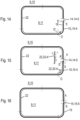
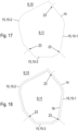
- three sections 15-1, 15-2, 15-3 of a cutting gap 15 are initially produced, which are separated from one another by webs 23, here for example micro-joints or nanojoints.
- the laser beam 16 is pierced away from the contour of the workpiece part 11, first guided to the contour of the workpiece part 11 and then guided along the contour.
- the cutting gap 15 is guided along a Figure 17 cutting line 14, not shown in detail. It is understood that a larger or smaller number of sections of the cutting gap 15 can be provided along the contour of the workpiece part 11, wherein the number of sections of the cutting gap 15 corresponds to the number of webs 23.
- FIG. 18 illustrated takes place after generating sections 15-1, 15-2, 15-3 of the cutting gap 15, a modification of the workpiece 9, wherein the laser beam 16 is guided along a modification line 18.
- the modification line 18 is laterally offset and arranged equidistant from the cutting line 14.
- the modification line 18 extends in particular also over the areas of the cutting line 14 in which a web 23 is arranged, ie a modification of the workpiece 9 also takes place in the area of the webs 23.
- a modification of the workpiece 9 can take place in a sufficient manner with correspondingly small-sized webs 23, since this only slightly affects the gas dynamics of the process gas.
- the webs 23 are severed, for example by means of the laser beam 16 or manually, and the workpiece part 11 is removed from the remaining workpiece 10. It is also conceivable that the webs 23 are severed by the modification of the workpiece 9 in the area of the webs 23, so that the modification simultaneously cuts free the workpiece part 11. This can be the case in particular if the webs 23 are designed as nanojoints with a reduced height.
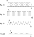
- the laser beam 16 When generating the cutting gap 15, the laser beam 16 is always guided in a straight line along the cutting line 14 (contour) of the workpiece part 11. When modifying the workpiece 9, the laser beam 16 is guided in a straight line or non-straight line along the modification line 18. In particular, when modifying the workpiece 9, the laser beam 16 can also have movement components transverse (perpendicular) to the modification line 18. This can be seen from the Figures 19 to 22 illustrated.
- FIG 19 a variant is illustrated in which the laser beam 16 is guided along closed circles 24 (ie closed path sections of the laser beam 16) which are arranged in rows along the modification line 18. After passing through a respective circle 24, the laser beam 16 is moved a short distance in a straight line along the modification line 18 and then guided along the next circle 24. In the direction of the modification line 18, the circles 24 overlap. Instead of Instead of circles, the laser beam 16 could also be guided along ellipses. The movement of the laser beam 16 thus has movement components in a straight line along the modification line 18 and transversely to the modification line 18.
- the modification zone 22, which results from the area of the workpiece 9 swept over by the laser beam 16, can be made relatively wide by this measure, in particular for producing deep and/or wide bevels.
- the laser beam 16 is guided in a meandering manner with back and forth movements along the modification line 18.
- the movement of the laser beam 16 includes movement components transverse to the modification line 18.
- the meandering movement of the laser beam 16 is rectangular, in Figure 21 triangular (sawtooth-shaped) and in Figure 22 sinusoidal. This is to be understood only as an example, although other meandering movements of the laser beam 16 are equally possible. Basically, any meandering back and forth movement of the laser beam 16 that extends along the modification line 18 is possible and provided according to the invention.
- a relatively wide modification zone 22 can also be created by the meandering movement of the laser beam 16, in particular for creating particularly deep and/or wide bevels.
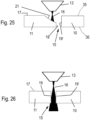
- the workpiece part-side cutting edge 19 adjacent to the upper workpiece surface 17 is provided with a bevel 21.
- the modification line 18 is offset laterally (e.g. equidistantly) relative to the cutting line 14, which in Figure 25 is not shown.
- the bevel 21 is created, for example, by several steps or modifications that are carried out on the same section of the cutting gap 15.
- the workpiece part 11 is irradiated in an area containing the workpiece-side cutting edge 19.
- the modification line 18 is offset laterally (e.g. equidistantly) relative to the cutting line 14 in the direction of the workpiece part 11.
- the laser beam 16 is moved in a meandering manner along the cutting line 14 or along circles or ellipses arranged in rows when generating the bevel 21, as can be seen from the Figures 19 to 22 whereby the width and/or depth of the bevel 21 can be significantly increased.
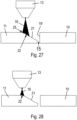
- the laser beam 16 When modifying the workpiece 9, the laser beam 16 simultaneously removes burrs from the workpiece part-side cutting edge 19 and from the remaining workpiece-side cutting edge 19' adjacent to the underside workpiece surface.
- the modification line 18 can be identical to the cutting line 14 or different from it, which in Figure 26 is not shown.
- the focus position of the laser beam 16 is adjusted so that the two cutting edges 19, 19' are irradiated accordingly.
- a cutting gap 15 is created.
- a bevel 21 is created on the workpiece-side cutting edge 19, whereby an adhesion in the form of slag 25 is formed.
- the slag 25 can be removed by the laser beam 16.
- step b) is carried out before step a)) are described.
- the laser beam 16 emerging from the nozzle 13 strike the upper workpiece surface 17.
- the laser beam 16 is in the form of a beam cone with a central beam axis 26 and is focused in a focus 27.
- the central beam axis 26, which corresponds to the axis of symmetry of the beam cone, is directed perpendicular to the first workpiece surface 17.
- the nozzle 13 has a relatively large working distance A from the first workpiece surface 17 and the focus 27 is located close to the nozzle 13, with the workpiece 9 being in the divergent region of the laser beam 16, which leads to a relatively wide beam spot 28 with a relatively large beam diameter D on the workpiece 9 or the upper workpiece surface 17.
- the beam diameter D is measured perpendicular to the beam axis 26 and at the point where the laser beam 16 strikes the workpiece 9.
- the focus position and thus the beam diameter D are selected such that the power density of the laser beam 16 on the workpiece 9 is relatively low and the laser beam 16 only creates a depression 29 and the workpiece 9 is not penetrated (non-separating processing).
- the movement of the laser beam 16 when creating the trough 29 basically comprises at least one horizontal movement component.
- the movement of the laser beam 16 can also be composed of two mutually perpendicular (e.g. horizontal) movement components (x and y directions), wherein the laser beam 16 is moved along a curved path 30, in particular along an open or closed circular path (see also Figure 34
- the path 30 of the laser beam 16 corresponds to the modification line 18.
- the Trough 29 therefore always has an elongated or elongated shape.
- the longitudinal shape or course of trough 29 can be freely defined.
- the trough 29 can optionally be given a defined cross-sectional shape.
- the focus position and thus the beam diameter D can be varied during the creation of the trough 29 in order to specifically adjust the depth and/or cross-sectional shape of the trough 29. If the beam diameter D on the workpiece 9 is reduced, the trough 29 becomes deeper, i.e. the flanks become steeper, whereas the trough 29 becomes flatter, i.e. the flanks become less steep, if the beam diameter D on the workpiece 9 is increased.
- FIG 34 the creation of an elongated trough 29 is illustrated schematically by way of example. Accordingly, the laser beam 16 is moved along a curved (non-rectilinear) path 30 along a modification line 18, whereby the trough 29 is created with a corresponding course.
- a cutting gap 15 is created within the trough 29, which is also Figure 33 is illustrated.
- the jet head 3 or the nozzle 13 is moved towards the upper surface of the workpiece 17 (in the vertical direction), so that in comparison to producing the trough 29 there is a significantly smaller working distance A between the nozzle 13 and the upper surface of the workpiece 17.
- the working distance A for producing the cutting gap 15 is, for example, at least 6 times smaller, in particular at least 10 times smaller, than the working distance A for producing the trough 29.
- the jet spot 28 and the jet diameter D on the workpiece are significantly smaller.
- the cross-sectional area of the jet spot 28 on the workpiece 9 is at least 6 times smaller, in particular at least 10 times smaller.
- the focus 27 of the laser beam 16 is located within the workpiece 9.
- the beam diameter D for generating the cutting gap 15 is dimensioned such that the power density of the laser beam 16 on the workpiece 9 leads to a separating machining (penetration) of the workpiece 9.
- Figure 35 When generating the cutting gap 15, the laser beam 16 is moved in a plane parallel to the plane of the workpiece support 5 (e.g. horizontal).
- the movement of the laser beam 16 when generating the cutting gap 15 comprises two mutually perpendicular (e.g. horizontal) movement components (x- and y-direction), whereby the laser beam 16 is moved along a cutting line 14, whereby the cutting gap 15 is generated.
- the cutting line 14 is arranged within the recess 29.
- the cutting line 14 corresponds to the contour of a workpiece part 11 to be cut out of the workpiece 9.
- the cutting line 14 here has, for example, a non-linear and non-circular course, whereby a circular course would also be possible.
- the trough 29 does not extend along the entire cutting line 14, but only along a section thereof.
- the cutting gap 15 is created within the trough 29 and extends beyond it.
- the cutting gap 15 has an elongated or elongated shape.
- the longitudinal shape or course of the cutting gap 15 can be freely defined, with the proviso that the cutting gap 15 always follows the cutting line 14 or contour of the workpiece part 11 and is formed within the trough 29.
- the course of the cutting gap 15 corresponds to the course of the trough 29.
- the paths of the laser beam 16 when creating the trough 29 and the cutting gap 15 are arranged equidistantly. As in Figure 35 illustrated, the laser beam 16 is guided beyond the depression 29 when the cutting gap 15 is created and the cutting gap 15 is closed so that the workpiece part 11 (in the form of an inner slug) is cut free from the workpiece 9. By separating the workpiece part 11 from the remaining workpiece 11, an opening or hole is created in the remaining workpiece 11.
- the trough 29 could, for example, have a circular, closed course, whereby the cutting gap 15 would therefore also have a circular, closed course following the course of the trough 29.
- a circular or disk-shaped workpiece part 11 would be cut out of the workpiece 9, so that a circular hole is created in the remaining workpiece 10.
- the workpiece part 11 is not completely cut out (cut free) by the laser beam 16, but that one or more webs (eg microjoints) remain between the workpiece part 11 and the remaining workpiece 10.
- the webs can be severed by the laser beam 16 or otherwise in order to remove the workpiece part 11 from the remaining workpiece 10.
- the workpiece part 11 could be broken out of the workpiece 9.
- the cutting gap 15 is always arranged within the trough 29, whereby the cutting gap 15 is generated parallel to the trough 29.
- the cutting gap 15 is arranged, for example, centered with respect to a direction perpendicular to the extension of the trough 29.
- the beam spot 28 for generating the cutting gap 15 is located only within the trough 29.
- the trough 29 is delimited or surrounded on the upper surface of the workpiece 17 by a (closed) trough edge 31.
- the trough 29 is a depression or recess of the workpiece 9 on the workpiece surface 17.
- the trough edge 31 is defined as that area of the workpiece 9 where the trough 29 begins to deepen towards the interior of the workpiece 9.
- the cutting gap 15 is always spaced from the trough edge 31 in a direction perpendicular to the extension of the trough 29 (in particular when viewed perpendicularly through the plane of the workpiece surface 17), i.e. the cutting gap 15 always has a distance from the trough edge 31 that is different from zero in a direction perpendicular to the extension of the trough 29.
- the cutting gap 15 is centered within the trough 29 in a direction perpendicular to the extension of the trough 29, always having a constant shortest distance to the trough edge 31.
- the cutting gap 15 is located in a vertical view through the flat workpiece surface 17 in a direction perpendicular to the extension of the trough 29 within the trough 29, i.e. in relation to a (vertical) projection of the cutting gap 15 and trough 29 into the plane of the workpiece surface 17.
- the trough 29 deepens towards the cutting gap 15, with the cutting gap 15 being arranged in the bottom of the trough.
- the trough 29 forms, for example, a rounding of the cutting edge of the cutting gap 15.
- the trough 29 is particularly advantageously designed such that it is a bevel 21 of the cutting gap 15.
- the cutting gap 15 is preferably designed as a closed gap, in particular as a ring-shaped closed gap (annular gap), so that a hole remains in the workpiece 9.
- the cutting gap 15 can then advantageously serve for fastening a workpiece part to be cut out of the workpiece 9, wherein a screw or rivet head can be countersunk in the remaining part of the trough 29, which serves as a bevel.
- the trough 29 has a trough section 32' on the remaining workpiece side and a trough section 32 on the workpiece part side.
- FIG 36 the remaining workpiece 10 is shown with hole 33 after removal of the workpiece part 11.
- the remaining workpiece 10 has the trough section 32' of the trough 29 remaining on the remaining workpiece 10 at the hole 33 (the other trough section 32 is located on the removed workpiece part 11).
- the trough section 32' can be designed as a chamfer, for example.
- the hole 33 it would also be possible to make the hole 33 circular and to form a completely circumferential trough section 32', for example in the form of a chamfer.
- the hole 33 possibly with one or more further holes, is advantageously located within the contour of a larger workpiece part 11', which can be cut out by the laser beam 16.
- a workpiece part 11' is indicated schematically using a contour.
- workpiece parts with holes, each of which has a chamfer can be produced particularly easily.
- the holes can be used in particular for fastening the workpiece part 11' that is cut out later.
- a depression 29 was created and then a cutting gap 15 was created within the depression 29. If a plurality of depressions 29 with a respective cutting gap 15 are created in the workpiece 9, it is possible that after the creation of a respective depression 29, the cutting gap 15 is created within the depression 29 immediately afterwards. However, it is also possible for several depressions 29 to be created in immediate succession without a cutting gap 15 being created between the creation of two depressions 29, followed by the creation of a cutting gap 15 within a respective depression 29, wherein the cutting gaps 15 are created in immediate succession without a depression 29 being created between the creation of two cutting gaps 15.
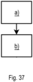
- FIG 37 a flow chart of the method according to the invention is illustrated.
- the method comprises cutting a section (15-1, 15-2, 15-3, 15-4, 15-5) of a cutting gap (15) severing the workpiece (9) along a cutting line (14) or cutting a closed cutting gap (15) along the cutting line (14), whereby cutting edges (19, 19') are formed on the workpiece part (11) and the remaining workpiece (10) (step a),
- the method further comprises producing a modification of the workpiece (9), selected from a chamfer (21), a rounding (34) and a depression (29), on a workpiece upper side (35) along a modification line (18), while the workpiece part (11) is connected to the remaining workpiece (10) (step b).
- the laser beam is aligned perpendicular to the workpiece surface.
- the gas pressure of the process gas in step b) is less than 7 bar and in particular between 3 bar and 6 bar.
- step a) a section (15-1, 15-2, 15-3, 15-4, 15-5) of the cutting gap (15) is produced along the cutting line (14), and then in step b) at least a part of at least one of the cutting edges (19, 19') on the workpiece part (11) or on the remaining workpiece (10) is provided with a chamfer (21) or a rounding (34).
- the invention provides a novel method for beam processing of a plate-shaped or tubular workpiece, in which the workpiece part that has not yet been cut free and/or the remaining workpiece is subjected to a modification by the laser beam along a modification line.
- This makes mechanical modification of the cut-free workpiece part unnecessary, so that the production of workpiece parts can be carried out more easily, more quickly and more cost-effectively.
- the rigid, fixed position between the workpiece part and the remaining workpiece allows a particularly precise modification of the workpiece part, in particular the part that has been cut out in part, to be carried out in a simple manner, so that high quality requirements can be met.
- the method according to the invention can be implemented in existing laser processing devices in a simple manner, without having to provide complex technical measures for this purpose. Rather, a desired modification of the workpiece can be realized by the method according to the invention by simply intervening in the machine control.
Landscapes
- Engineering & Computer Science (AREA)
- Physics & Mathematics (AREA)
- Optics & Photonics (AREA)
- Plasma & Fusion (AREA)
- Mechanical Engineering (AREA)
- Laser Beam Processing (AREA)
Claims (14)
- Procédé de fabrication d'au moins une partie de pièce (11) et d'un élément restant de la pièce (10) à partir d'une pièce (9), au moyen d'un faisceau laser (16) et d'un gaz de processus s'échappant conjointement d'une buse (13) d'une tête de traitement laser (2) pour l'expulsion du matériau de la pièce fondu, incluant les étapes suivantes :Étape a) : Découpe d'une section (15-1, 15-2, 15-3, 15-4, 15-5) d'un interstice de coupe (15) traversant la pièce (9) le long d'une ligne de coupe (14) ou découpe d'un interstice de coupe fermé (15) le long de la ligne de coupe (14), dans lequel des arêtes de coupe (19, 19') sont formés sur la partie de pièce (11) et sur l'élément restant de la pièce (10),Étape b) : Production d'une modification de la pièce (9), choisie parmi un chanfrein (21) et un arrondi (34), sur une face supérieure de la pièce (35) le long d'une ligne de modification (18), tandis que la partie de pièce (11) reste lié à l'élément restant de la pièce (10),dans lequel le faisceau laser (16) est orienté de façon perpendiculaire à une surface de la pièce (17) de la face supérieure de la pièce (35) aux étapes a) et b), et caractérisé ainsi en ce que- l'étape a) est réalisée avant l'étape b), dans laquelle, à l'étape a), une section (15-1, 15-2, 15-3, 15-4, 15-5) de l'interstice de coupe (15) le long de la ligne de coupe (14) est générée, et ensuite, à l'étape b), au moins une partie d'au moins une des arêtes de coupe (19, 19') de la partie de pièce (11) ou de l'élément restant de la pièce (10) est dotée d'un chanfrein (21) ou d'un arrondi (34), dans lequel la pression de gaz du gaz de processus avant sa sortie de la buse à l'étape b) est inférieure à 7 bars, en particulier entre 3 et 6 bars.
- Procédé selon la revendication 1, au cours duquel, à l'étape b), une distance (A) entre une buse (13) émettant le faisceau laser (16) et la surface de la pièce (17) est supérieure à celle de l'étape a), dans lequel la distance (A) entre la buse (13) émettant le faisceau laser (16) et la surface de la pièce (17) esti) au moins de 9 mm, au moins de 20 mm ou au moins de 35 mm lors de la production d'un chanfrein (21) avec de l'oxygène comme gaz de processus, ouii) au moins de 1 mm, au moins de 6 mm ou au moins de 9 mm lors de la production d'un arrondi (34) avec de l'azote comme gaz de processus.
- Procédé selon la revendication 1 ou 2, au cours duquel, à l'étape b) :i) le foyer (27) du faisceau laser (16) se situe sur ou au-dessus de la surface de la pièce (17),ii) la puissance moyenne du faisceau laser (16) est inférieure à 3500 W,iii) le diamètre du foyer (D) du faisceau laser (16) est d'au moins 150 µm, et/ouvii) la vitesse d'avance de la tête de traitement laser (2) est d'au moins 1 m/min.
- Procédé selon l'une des revendications 1 à 3, dans lequel, pour une pièce (9) en acier de construction, de l'oxygène est utilisé comme gaz de processus à l'étape b).
- Procédé selon l'une des revendications 1 à 4, au cours duquel la densité de puissance du faisceau laser (16) à l'étape b) est réduite par rapport à la densité de puissance à l'étape a), en :i) réduisant la puissance du faisceau laser (16),ii) augmentant la vitesse d'avance du faisceau laser (16),iii) défocalisant le faisceau laser (16) par modification de la position du foyer, et/ouiv) modifiant un diamètre de faisceau (D) du faisceau laser (16) sur la surface de la pièce (17).
- Procédé selon l'une des revendications 1 à 5, dans lequel la ligne de coupe (14) et la ligne de modification (18) s'étendent parallèlement, et un décalage latéral entre la ligne de coupe (14) et la ligne de modification (18) est d'au moins 0,2 mm et d'au plus 1,5 mm.
- Procédé selon l'une des revendications 1 à 6, au cours duquel, à l'étape b), le faisceau laser (16) se déplace toujours en ligne droite le long de la ligne de modification (18).
- Procédé selon l'une des revendications 1 à 6, au cours duquel, à l'étape b), le déplacement du faisceau laser (16) le long de la ligne de modification (18) présente des composantes de déplacement perpendiculaires à la ligne de modification (18), dans lequel le faisceau laser (16) en particulieri) effectue un mouvement d'oscillation de forme sinusoïdale le long de la ligne de modification (18), et/ouii) est déplacé le long de sections de trajectoire fermées, en particulier des cercles (24) ou ellipses fermés, disposés le long de la ligne de modification (18).
- Procédé selon la revendication 8, au cours duqueli) une composante de déplacement du faisceau laser (16) perpendiculaire à la ligne de modification (18) présente une amplitude d'au moins 0,5 mm et d'au plus 5 mm, et/ouii) un chevauchement des sections de trajectoire (24) fermées du faisceau laser (16) le long de la ligne de modification (18) se situe dans une fourchette de 0,5 mm à 1 mm.
- Procédé selon l'une des revendications 1 à 9, au cours duquel, après les étapes a) et b), une étape c) supplémentaire est réalisée, laquelle comprend :- l'élimination des scories (25) formées au cours des étapes a) et b) sur au moins une des arêtes de coupe (19, 19') de la partie de pièce (11) ou de l'élément restant de la pièce (10), dans lequel le faisceau laser (16) est manoeuvré le long de la ligne de coupe (14) ou d'une ligne décalée latéralement par rapport à celle-ci, et/ou- l'élimination des scories (25) formées au cours des étapes a) et b) d'un chanfrein (21) ou d'un arrondi (34), dans lequel le faisceau laser (16) est manoeuvré le long de la ligne de modification (18) ou d'une ligne décalée latéralement par rapport à celle-ci.
- Procédé selon la revendication 10, au cours duquel, à l'étape c)i) une puissance du laser est inférieure à une puissance du laser à l'étape a), et est en particulier inférieure à 1000 W,ii) la distance (A) entre la buse (13) et la surface de la pièce (17) est supérieure à celle de l'étape a), et est en particulier au moins de 5 mm, en particulier entre 6 mm et 12 mm,iii) la pression de gaz est inférieure à 7 bars, en particulier entre 0,7 bar et 6 bars, et/ouiv) le diamètre du foyer (D) du faisceau laser (16) est d'au moins 150 µm.
- Procédé selon l'une des revendications 10 ou 11, au cours duquel le faisceau laser (16) utilisé à l'étape c) permet une dissociation par découpe de la partie de pièce (11) de l'élément restant de la pièce (10), dans lequel une puissance laser du faisceau laser (16) est en particulier d'au moins 500 W.
- Procédé selon la revendication 1, au cours duquel,i) une pluralité d'étapes a) est réalisée avant une ou plusieurs étapes b), et/ouii) une pluralité d'étapes a) et une pluralité d'étapes b) sont réalisées selon une séquence alternée, dans laquelle après une étape portant l'une des désignations, une étape portant l'autre désignation est respectivement réalisée.
- Procédé selon l'une des revendications 1 à 13, au cours duquel, lorsqu'une ou plusieurs étapes a) sont réalisées avant une ou plusieurs étapes b), une ou plusieurs sections (15-1, 15-2, 15-3) de l'interstice de coupe (15) le long de la ligne de coupe (14) sont générées, dans lequel la partie de pièce (11) reste liée à l'élément restant de la pièce (10) par un ou plusieurs ponts de maintien (23), en particulier des micro-joints ou nanojoints, et ensuite, au cours de ladite une ou plusieurs étapes b), au moins une partie d'au moins une des arêtes de coupe (19, 19') sur la partie de pièce (11) ou l'élément restant de la pièce (10) ainsi que des ponts de maintien (23) sont dotés d'un chanfrein (21) ou d'un arrondi (34).
Priority Applications (1)
| Application Number | Priority Date | Filing Date | Title |
|---|---|---|---|
| PL20767480.5T PL4200101T3 (pl) | 2020-08-21 | 2020-08-21 | Sposób wytwarzania co najmniej jednej części przedmiotu poddawanego obróbce oraz pozostałej części przedmiotu poddawanego obróbce z przedmiotu poddawanego obróbce |
Applications Claiming Priority (1)
| Application Number | Priority Date | Filing Date | Title |
|---|---|---|---|
| PCT/EP2020/073578 WO2022037797A1 (fr) | 2020-08-21 | 2020-08-21 | Procédé de production d'au moins une partie de pièce à usiner et d'une pièce à usiner résiduelle à partir d'une pièce à usiner |
Publications (2)
| Publication Number | Publication Date |
|---|---|
| EP4200101A1 EP4200101A1 (fr) | 2023-06-28 |
| EP4200101B1 true EP4200101B1 (fr) | 2025-02-19 |
Family
ID=72355946
Family Applications (1)
| Application Number | Title | Priority Date | Filing Date |
|---|---|---|---|
| EP20767480.5A Active EP4200101B1 (fr) | 2020-08-21 | 2020-08-21 | Procédé de production d'au moins une partie de pièce à usiner et d'une pièce à usiner résiduelle à partir d'une pièce à usiner |
Country Status (4)
| Country | Link |
|---|---|
| EP (1) | EP4200101B1 (fr) |
| CN (1) | CN114390958A (fr) |
| PL (1) | PL4200101T3 (fr) |
| WO (1) | WO2022037797A1 (fr) |
Families Citing this family (9)
| Publication number | Priority date | Publication date | Assignee | Title |
|---|---|---|---|---|
| CN117858779A (zh) | 2021-08-25 | 2024-04-09 | 海别得公司 | 使用材料处理系统的边缘整形 |
| DE102022104779A1 (de) * | 2022-03-01 | 2023-09-07 | TRUMPF Werkzeugmaschinen SE + Co. KG | Verfahren zur Bearbeitung eines platten- oder rohrförmigen Werkstücks |
| DE102022104791A1 (de) * | 2022-03-01 | 2023-09-07 | TRUMPF Werkzeugmaschinen SE + Co. KG | Verfahren zur Bearbeitung eines platten- oder rohrförmigen Werkstücks |
| DE102022112212A1 (de) * | 2022-05-16 | 2023-11-16 | TRUMPF Werkzeugmaschinen SE + Co. KG | Technik zum Erzeugen einer Kantenverrundung |
| WO2024069758A1 (fr) * | 2022-09-27 | 2024-04-04 | ファナック株式会社 | Dispositif d'usinage au laser et procédé d'usinage au laser |
| DE102022127687A1 (de) | 2022-10-20 | 2024-04-25 | TRUMPF Werkzeugmaschinen SE + Co. KG | Verfahren zum Erzeugen eines dickenreduzierten Verbindungsstegs beim Schneiden eines Werkstückteils aus einem plattenartigen Werkstück sowie zugehöriges Steuerungsprogrammprodukt |
| DE102022127956A1 (de) | 2022-10-21 | 2024-05-02 | TRUMPF Werkzeugmaschinen SE + Co. KG | Verfahren zum bearbeiten eines metallischen werkstücks sowie lasereinrichtung |
| DE102022128170A1 (de) * | 2022-10-25 | 2024-04-25 | TRUMPF Werkzeugmaschinen SE + Co. KG | Technik zum Verrunden einer Werkstückkante |
| CN115846911B (zh) * | 2023-02-23 | 2023-05-09 | 福建盈浩文化创意股份有限公司 | 一种悬挂式框画用激光切割设备 |
Citations (4)
| Publication number | Priority date | Publication date | Assignee | Title |
|---|---|---|---|---|
| JPH08108287A (ja) | 1994-10-07 | 1996-04-30 | Seiji Ishibe | 面取り加工方法 |
| JP2002210577A (ja) | 2001-01-17 | 2002-07-30 | Amada Eng Center Co Ltd | レーザによるr面取り加工方法および同方法の実施に適したレーザ加工ヘッド |
| US20160059349A1 (en) | 2014-02-28 | 2016-03-03 | Ipg Photonics Corporation | Multi-laser system and method for cutting and post-cut processing hard dielectric materials |
| US20170001266A1 (en) | 2015-07-01 | 2017-01-05 | Apple Inc. | Enhancing strength in laser cutting of ceramic components |
Family Cites Families (10)
| Publication number | Priority date | Publication date | Assignee | Title |
|---|---|---|---|---|
| DE19549666B4 (de) * | 1994-02-28 | 2008-01-03 | Mitsubishi Denki K.K. | Laserstrahlbearbeitungsverfahren und Laserstrahlmaschine |
| TW419867B (en) * | 1998-08-26 | 2001-01-21 | Samsung Electronics Co Ltd | Laser cutting apparatus and method |
| US9346130B2 (en) * | 2008-12-17 | 2016-05-24 | Electro Scientific Industries, Inc. | Method for laser processing glass with a chamfered edge |
| JP4976576B2 (ja) * | 2010-11-01 | 2012-07-18 | 住友電気工業株式会社 | 切削工具とその製造方法および製造装置 |
| CN104822485B (zh) * | 2012-11-30 | 2017-08-08 | 夏伊洛工业公司 | 在金属板材件中形成焊接凹口的方法 |
| US10442719B2 (en) * | 2013-12-17 | 2019-10-15 | Corning Incorporated | Edge chamfering methods |
| WO2016033494A1 (fr) * | 2014-08-28 | 2016-03-03 | Ipg Photonics Corporation | Systeme et procede de biseautage et/ou de polissage par laser |
| US10384306B1 (en) * | 2015-06-10 | 2019-08-20 | Seagate Technology Llc | Laser cutting array with multiple laser source arrangement |
| DE102017213394B4 (de) | 2017-08-02 | 2020-03-26 | Trumpf Werkzeugmaschinen Gmbh + Co. Kg | Verfahren zum Laserschneiden plattenförmiger Werkstücke und zugehöriges Computerprogrammprodukt |
| KR102174428B1 (ko) * | 2019-11-27 | 2020-11-04 | 엘지디스플레이 주식회사 | 플렉서블 기판의 제조방법 |
-
2020
- 2020-08-21 PL PL20767480.5T patent/PL4200101T3/pl unknown
- 2020-08-21 CN CN202080053976.9A patent/CN114390958A/zh active Pending
- 2020-08-21 EP EP20767480.5A patent/EP4200101B1/fr active Active
- 2020-08-21 WO PCT/EP2020/073578 patent/WO2022037797A1/fr not_active Ceased
Patent Citations (4)
| Publication number | Priority date | Publication date | Assignee | Title |
|---|---|---|---|---|
| JPH08108287A (ja) | 1994-10-07 | 1996-04-30 | Seiji Ishibe | 面取り加工方法 |
| JP2002210577A (ja) | 2001-01-17 | 2002-07-30 | Amada Eng Center Co Ltd | レーザによるr面取り加工方法および同方法の実施に適したレーザ加工ヘッド |
| US20160059349A1 (en) | 2014-02-28 | 2016-03-03 | Ipg Photonics Corporation | Multi-laser system and method for cutting and post-cut processing hard dielectric materials |
| US20170001266A1 (en) | 2015-07-01 | 2017-01-05 | Apple Inc. | Enhancing strength in laser cutting of ceramic components |
Non-Patent Citations (9)
| Title |
|---|
| "Faszination Blech : flexible Bearbeitung eines vielseitigen Werkstoffs", 1 January 1996, RAABE, Stuttgart, ISBN: 3-88649-187-0, article H. BITZEL ET AL.: "Kapitel 7 Laserschneiden", pages: 68 - 83, XP009565509 |
| ANONYMOUS: "Laser Schneidtechnologie", BYSTRONIC, 1 January 2007 (2007-01-01), pages 1 - 264, XP055915186 |
| ANONYMOUS: "technical information Micro-Joints ", TRUMPF TECHNICAL INFORMATION, 1 September 1996 (1996-09-01), XP055943903 |
| D10 - GRUNDKURS SCHNEIDTECHNOLOGIE FÜR KUNDEN 2004 |
| D10A - KURSORDNER BASIC COURSE CUTTING TECHNOLOGY FÜR KUNDEN |
| D10B - PARTICIPANTS CONFIRMATION_BASIC COURSE CUTTING TECHN. |
| D7 - C. DAUM:TRUMPF-AUS DER PRAXIS - 98 PROZENT WENIGER KOLLISIONEN BEIM LASERSCHNEIDEN SOMMER 2016 (DATE?) |
| H. BITZEL ET AL.: "Faszination Blech : flexible Bearbeitung eines vielseitigen Werkstoffs", 1 January 1996, RAABE, Stuttgart, ISBN: 3-88649-187-0, article H. BITZEL ET AL.: "Blechteile fertigen - Das NC-Programm weiß, wie's geht.", pages: 30 - 41, XP009565508 |
| H. BITZEL ET AL.: "Faszination Blech : flexible Bearbeitung eines vielseitigen Werkstoffs", 1 January 1996, RAABE, Stuttgart, ISBN: 3-88649-187-0, article H. BITZEL ET AL.: "Glossar", pages: 158 - 160, XP009565510 |
Also Published As
| Publication number | Publication date |
|---|---|
| WO2022037797A1 (fr) | 2022-02-24 |
| EP4200101A1 (fr) | 2023-06-28 |
| PL4200101T3 (pl) | 2025-06-09 |
| CN114390958A (zh) | 2022-04-22 |
Similar Documents
| Publication | Publication Date | Title |
|---|---|---|
| WO2022037797A1 (fr) | Procédé de production d'au moins une partie de pièce à usiner et d'une pièce à usiner résiduelle à partir d'une pièce à usiner | |
| EP4035823B1 (fr) | Procédé d'usinage par faisceau d'une pièce tabulaire ou tubulaire | |
| EP3965990B1 (fr) | Procédé et dispositif de traitement au laser d'une pièce | |
| EP3007852B1 (fr) | Procédé de rainurage dans des composants métalliques en utilisant un faisceau laser | |
| EP1945401B2 (fr) | Dispositif et methode pour separer un materiel, utilisant un laser pulse, l'energie d'un pulse etant inferieure a l'energie d'un pulse necessaire pour separer le materiel | |
| EP4238687B1 (fr) | Procédé d'usinage d'une pièce à usiner en forme de plaque ou de tube | |
| DE102017213394B4 (de) | Verfahren zum Laserschneiden plattenförmiger Werkstücke und zugehöriges Computerprogrammprodukt | |
| EP4238690B1 (fr) | Procédé d'usinage d'une pièce en forme de plaque ou de tube | |
| EP3983168A1 (fr) | Procédé d'usinage par faisceau d'une pièce de fabrication tabulaire ou tubulaire | |
| EP3528995B1 (fr) | Méthode de découpe au laser | |
| WO2014060091A1 (fr) | Découpeuse à laser et procédé permettant de découper des pièces de différentes épaisseurs | |
| EP3007853B1 (fr) | Méthode d'élimination des bavures formées sur la surface d'une pièce dans un procédé de création d'un trou traversant au moyen d'un rayon laser | |
| DE102012217766B4 (de) | Verfahren und Vorrichtung zum Dampfdruck-Abtragschneiden eines metallischen Werkstücks | |
| DE102021005297A1 (de) | Verfahren zur Erzeugung angesenkter Löcher | |
| WO2023072568A1 (fr) | Procédé de fabrication de parties de pièces présentant des arêtes de coupe chanfreinées | |
| DE10204428A1 (de) | Verfahren zum Abtragen von Vertiefungen durch einen Laser sowie Wabenstrukturformwerkzeug und Verfahren zum Herstellen dieses Werkzeugs | |
| DE3801068A1 (de) | Verfahren und vorrichtung zum abtragen mittels gebuendelter energiestrahlen | |
| WO2023072641A1 (fr) | Procédé de réalisation de trous chanfreinés par usinage laser | |
| WO2023072567A1 (fr) | Procédé d'usinage d'une pièce par faisceau laser à énergie par unité de longueur constante du faisceau laser | |
| WO2024061775A1 (fr) | Procédé combinant poinçon et laser et machine combinant poinçon et laser pour l'usinage d'une pièce, programme informatique et support de stockage lisible par ordinateur | |
| EP3736074B1 (fr) | Procédé de découpe par séparation d'une pluralité de pièces | |
| WO2021152008A1 (fr) | Ensemble de traitement de matériau à l'aide d'un faisceau laser, notamment destiné au perçage par laser | |
| DE102024112208A1 (de) | Verfahren und Laserschneidevorrichtung zum Erzeugen einer Fase an einem Schnittspalt in einem Werkstück mittels eines Laserschneidkopfes | |
| DE102023128123A1 (de) | Verfahren zum Laserschneiden mit Schnittspaltkantenprofilierung | |
| WO2024068253A1 (fr) | Procédé de découpe au laser de pièces en forme de plaque, et produit programme informatique associé |
Legal Events
| Date | Code | Title | Description |
|---|---|---|---|
| STAA | Information on the status of an ep patent application or granted ep patent |
Free format text: STATUS: UNKNOWN |
|
| STAA | Information on the status of an ep patent application or granted ep patent |
Free format text: STATUS: THE INTERNATIONAL PUBLICATION HAS BEEN MADE |
|
| PUAI | Public reference made under article 153(3) epc to a published international application that has entered the european phase |
Free format text: ORIGINAL CODE: 0009012 |
|
| STAA | Information on the status of an ep patent application or granted ep patent |
Free format text: STATUS: REQUEST FOR EXAMINATION WAS MADE |
|
| 17P | Request for examination filed |
Effective date: 20230214 |
|
| AK | Designated contracting states |
Kind code of ref document: A1 Designated state(s): AL AT BE BG CH CY CZ DE DK EE ES FI FR GB GR HR HU IE IS IT LI LT LU LV MC MK MT NL NO PL PT RO RS SE SI SK SM TR |
|
| DAV | Request for validation of the european patent (deleted) | ||
| DAX | Request for extension of the european patent (deleted) | ||
| GRAP | Despatch of communication of intention to grant a patent |
Free format text: ORIGINAL CODE: EPIDOSNIGR1 |
|
| STAA | Information on the status of an ep patent application or granted ep patent |
Free format text: STATUS: GRANT OF PATENT IS INTENDED |
|
| INTG | Intention to grant announced |
Effective date: 20241001 |
|
| GRAS | Grant fee paid |
Free format text: ORIGINAL CODE: EPIDOSNIGR3 |
|
| GRAA | (expected) grant |
Free format text: ORIGINAL CODE: 0009210 |
|
| STAA | Information on the status of an ep patent application or granted ep patent |
Free format text: STATUS: THE PATENT HAS BEEN GRANTED |
|
| AK | Designated contracting states |
Kind code of ref document: B1 Designated state(s): AL AT BE BG CH CY CZ DE DK EE ES FI FR GB GR HR HU IE IS IT LI LT LU LV MC MK MT NL NO PL PT RO RS SE SI SK SM TR |
|
| REG | Reference to a national code |
Ref country code: GB Ref legal event code: FG4D Free format text: NOT ENGLISH |
|
| REG | Reference to a national code |
Ref country code: CH Ref legal event code: EP |
|
| REG | Reference to a national code |
Ref country code: IE Ref legal event code: FG4D Free format text: LANGUAGE OF EP DOCUMENT: GERMAN |
|
| REG | Reference to a national code |
Ref country code: DE Ref legal event code: R096 Ref document number: 502020010437 Country of ref document: DE |
|
| REG | Reference to a national code |
Ref country code: NL Ref legal event code: MP Effective date: 20250219 |
|
| PG25 | Lapsed in a contracting state [announced via postgrant information from national office to epo] |
Ref country code: RS Free format text: LAPSE BECAUSE OF FAILURE TO SUBMIT A TRANSLATION OF THE DESCRIPTION OR TO PAY THE FEE WITHIN THE PRESCRIBED TIME-LIMIT Effective date: 20250519 |
|
| PG25 | Lapsed in a contracting state [announced via postgrant information from national office to epo] |
Ref country code: FI Free format text: LAPSE BECAUSE OF FAILURE TO SUBMIT A TRANSLATION OF THE DESCRIPTION OR TO PAY THE FEE WITHIN THE PRESCRIBED TIME-LIMIT Effective date: 20250219 |
|
| PG25 | Lapsed in a contracting state [announced via postgrant information from national office to epo] |
Ref country code: ES Free format text: LAPSE BECAUSE OF FAILURE TO SUBMIT A TRANSLATION OF THE DESCRIPTION OR TO PAY THE FEE WITHIN THE PRESCRIBED TIME-LIMIT Effective date: 20250219 |
|
| REG | Reference to a national code |
Ref country code: LT Ref legal event code: MG9D |
|
| PG25 | Lapsed in a contracting state [announced via postgrant information from national office to epo] |
Ref country code: NO Free format text: LAPSE BECAUSE OF FAILURE TO SUBMIT A TRANSLATION OF THE DESCRIPTION OR TO PAY THE FEE WITHIN THE PRESCRIBED TIME-LIMIT Effective date: 20250519 Ref country code: IS Free format text: LAPSE BECAUSE OF FAILURE TO SUBMIT A TRANSLATION OF THE DESCRIPTION OR TO PAY THE FEE WITHIN THE PRESCRIBED TIME-LIMIT Effective date: 20250619 |
|
| PG25 | Lapsed in a contracting state [announced via postgrant information from national office to epo] |
Ref country code: NL Free format text: LAPSE BECAUSE OF FAILURE TO SUBMIT A TRANSLATION OF THE DESCRIPTION OR TO PAY THE FEE WITHIN THE PRESCRIBED TIME-LIMIT Effective date: 20250219 |
|
| PG25 | Lapsed in a contracting state [announced via postgrant information from national office to epo] |
Ref country code: HR Free format text: LAPSE BECAUSE OF FAILURE TO SUBMIT A TRANSLATION OF THE DESCRIPTION OR TO PAY THE FEE WITHIN THE PRESCRIBED TIME-LIMIT Effective date: 20250219 |
|
| PG25 | Lapsed in a contracting state [announced via postgrant information from national office to epo] |
Ref country code: PT Free format text: LAPSE BECAUSE OF FAILURE TO SUBMIT A TRANSLATION OF THE DESCRIPTION OR TO PAY THE FEE WITHIN THE PRESCRIBED TIME-LIMIT Effective date: 20250620 Ref country code: LV Free format text: LAPSE BECAUSE OF FAILURE TO SUBMIT A TRANSLATION OF THE DESCRIPTION OR TO PAY THE FEE WITHIN THE PRESCRIBED TIME-LIMIT Effective date: 20250219 |
|
| PG25 | Lapsed in a contracting state [announced via postgrant information from national office to epo] |
Ref country code: BG Free format text: LAPSE BECAUSE OF FAILURE TO SUBMIT A TRANSLATION OF THE DESCRIPTION OR TO PAY THE FEE WITHIN THE PRESCRIBED TIME-LIMIT Effective date: 20250219 Ref country code: GR Free format text: LAPSE BECAUSE OF FAILURE TO SUBMIT A TRANSLATION OF THE DESCRIPTION OR TO PAY THE FEE WITHIN THE PRESCRIBED TIME-LIMIT Effective date: 20250520 |
|
| PG25 | Lapsed in a contracting state [announced via postgrant information from national office to epo] |
Ref country code: SE Free format text: LAPSE BECAUSE OF FAILURE TO SUBMIT A TRANSLATION OF THE DESCRIPTION OR TO PAY THE FEE WITHIN THE PRESCRIBED TIME-LIMIT Effective date: 20250219 |
|
| PG25 | Lapsed in a contracting state [announced via postgrant information from national office to epo] |
Ref country code: SM Free format text: LAPSE BECAUSE OF FAILURE TO SUBMIT A TRANSLATION OF THE DESCRIPTION OR TO PAY THE FEE WITHIN THE PRESCRIBED TIME-LIMIT Effective date: 20250219 |
|
| PG25 | Lapsed in a contracting state [announced via postgrant information from national office to epo] |
Ref country code: DK Free format text: LAPSE BECAUSE OF FAILURE TO SUBMIT A TRANSLATION OF THE DESCRIPTION OR TO PAY THE FEE WITHIN THE PRESCRIBED TIME-LIMIT Effective date: 20250219 |
|
| PGFP | Annual fee paid to national office [announced via postgrant information from national office to epo] |
Ref country code: DE Payment date: 20250820 Year of fee payment: 6 |
|
| PGFP | Annual fee paid to national office [announced via postgrant information from national office to epo] |
Ref country code: IT Payment date: 20250825 Year of fee payment: 6 Ref country code: PL Payment date: 20250721 Year of fee payment: 6 |
|
| PG25 | Lapsed in a contracting state [announced via postgrant information from national office to epo] |
Ref country code: EE Free format text: LAPSE BECAUSE OF FAILURE TO SUBMIT A TRANSLATION OF THE DESCRIPTION OR TO PAY THE FEE WITHIN THE PRESCRIBED TIME-LIMIT Effective date: 20250219 Ref country code: CZ Free format text: LAPSE BECAUSE OF FAILURE TO SUBMIT A TRANSLATION OF THE DESCRIPTION OR TO PAY THE FEE WITHIN THE PRESCRIBED TIME-LIMIT Effective date: 20250219 |
|
| PG25 | Lapsed in a contracting state [announced via postgrant information from national office to epo] |
Ref country code: RO Free format text: LAPSE BECAUSE OF FAILURE TO SUBMIT A TRANSLATION OF THE DESCRIPTION OR TO PAY THE FEE WITHIN THE PRESCRIBED TIME-LIMIT Effective date: 20250219 |
|
| PG25 | Lapsed in a contracting state [announced via postgrant information from national office to epo] |
Ref country code: SK Free format text: LAPSE BECAUSE OF FAILURE TO SUBMIT A TRANSLATION OF THE DESCRIPTION OR TO PAY THE FEE WITHIN THE PRESCRIBED TIME-LIMIT Effective date: 20250219 |
|
| REG | Reference to a national code |
Ref country code: DE Ref legal event code: R026 Ref document number: 502020010437 Country of ref document: DE |
|
| PLBI | Opposition filed |
Free format text: ORIGINAL CODE: 0009260 |
|
| REG | Reference to a national code |
Ref country code: CH Ref legal event code: L10 Free format text: ST27 STATUS EVENT CODE: U-0-0-L10-L00 (AS PROVIDED BY THE NATIONAL OFFICE) Effective date: 20251126 |
|
| PLAX | Notice of opposition and request to file observation + time limit sent |
Free format text: ORIGINAL CODE: EPIDOSNOBS2 |
|
| 26 | Opposition filed |
Opponent name: BYSTRONIC LASER AG Effective date: 20251119 |
|
| REG | Reference to a national code |
Ref country code: CH Ref legal event code: H13 Free format text: ST27 STATUS EVENT CODE: U-0-0-H10-H13 (AS PROVIDED BY THE NATIONAL OFFICE) Effective date: 20260324 |
|
| PG25 | Lapsed in a contracting state [announced via postgrant information from national office to epo] |
Ref country code: MC Free format text: LAPSE BECAUSE OF FAILURE TO SUBMIT A TRANSLATION OF THE DESCRIPTION OR TO PAY THE FEE WITHIN THE PRESCRIBED TIME-LIMIT Effective date: 20250219 |
|
| PLBB | Reply of patent proprietor to notice(s) of opposition received |
Free format text: ORIGINAL CODE: EPIDOSNOBS3 |
|
| PG25 | Lapsed in a contracting state [announced via postgrant information from national office to epo] |
Ref country code: LU Free format text: LAPSE BECAUSE OF NON-PAYMENT OF DUE FEES Effective date: 20250821 |
|
| PG25 | Lapsed in a contracting state [announced via postgrant information from national office to epo] |
Ref country code: CH Free format text: LAPSE BECAUSE OF NON-PAYMENT OF DUE FEES Effective date: 20250831 |
|
| GBPC | Gb: european patent ceased through non-payment of renewal fee |
Effective date: 20250821 |
|
| REG | Reference to a national code |
Ref country code: BE Ref legal event code: MM Effective date: 20250831 |
|
| PG25 | Lapsed in a contracting state [announced via postgrant information from national office to epo] |
Ref country code: LT Free format text: LAPSE BECAUSE OF FAILURE TO SUBMIT A TRANSLATION OF THE DESCRIPTION OR TO PAY THE FEE WITHIN THE PRESCRIBED TIME-LIMIT Effective date: 20250219 |
|
| PG25 | Lapsed in a contracting state [announced via postgrant information from national office to epo] |
Ref country code: GB Free format text: LAPSE BECAUSE OF NON-PAYMENT OF DUE FEES Effective date: 20250821 |
|
| PG25 | Lapsed in a contracting state [announced via postgrant information from national office to epo] |
Ref country code: IE Free format text: LAPSE BECAUSE OF NON-PAYMENT OF DUE FEES Effective date: 20250821 Ref country code: BE Free format text: LAPSE BECAUSE OF NON-PAYMENT OF DUE FEES Effective date: 20250831 |
|
| PG25 | Lapsed in a contracting state [announced via postgrant information from national office to epo] |
Ref country code: FR Free format text: LAPSE BECAUSE OF NON-PAYMENT OF DUE FEES Effective date: 20250831 |