EP4200527B1 - Windturbine mit vertikaler achse und verfahren zur verbindung von schaufel und strebe - Google Patents
Windturbine mit vertikaler achse und verfahren zur verbindung von schaufel und strebe Download PDFInfo
- Publication number
- EP4200527B1 EP4200527B1 EP21883404.2A EP21883404A EP4200527B1 EP 4200527 B1 EP4200527 B1 EP 4200527B1 EP 21883404 A EP21883404 A EP 21883404A EP 4200527 B1 EP4200527 B1 EP 4200527B1
- Authority
- EP
- European Patent Office
- Prior art keywords
- strut
- blade
- fastening member
- wind turbine
- vertical axis
- Prior art date
- Legal status (The legal status is an assumption and is not a legal conclusion. Google has not performed a legal analysis and makes no representation as to the accuracy of the status listed.)
- Active
Links
Images


Classifications
-
- F—MECHANICAL ENGINEERING; LIGHTING; HEATING; WEAPONS; BLASTING
- F03—MACHINES OR ENGINES FOR LIQUIDS; WIND, SPRING, OR WEIGHT MOTORS; PRODUCING MECHANICAL POWER OR A REACTIVE PROPULSIVE THRUST, NOT OTHERWISE PROVIDED FOR
- F03D—WIND MOTORS
- F03D3/00—Wind motors with rotation axis substantially perpendicular to the air flow entering the rotor
- F03D3/06—Rotors
- F03D3/062—Rotors characterised by their construction elements
- F03D3/064—Fixing wind engaging parts to rest of rotor
-
- F—MECHANICAL ENGINEERING; LIGHTING; HEATING; WEAPONS; BLASTING
- F03—MACHINES OR ENGINES FOR LIQUIDS; WIND, SPRING, OR WEIGHT MOTORS; PRODUCING MECHANICAL POWER OR A REACTIVE PROPULSIVE THRUST, NOT OTHERWISE PROVIDED FOR
- F03D—WIND MOTORS
- F03D1/00—Wind motors with rotation axis substantially parallel to the air flow entering the rotor
- F03D1/06—Rotors
- F03D1/065—Rotors characterised by their construction elements
- F03D1/0658—Arrangements for fixing wind-engaging parts to a hub
-
- F—MECHANICAL ENGINEERING; LIGHTING; HEATING; WEAPONS; BLASTING
- F03—MACHINES OR ENGINES FOR LIQUIDS; WIND, SPRING, OR WEIGHT MOTORS; PRODUCING MECHANICAL POWER OR A REACTIVE PROPULSIVE THRUST, NOT OTHERWISE PROVIDED FOR
- F03D—WIND MOTORS
- F03D3/00—Wind motors with rotation axis substantially perpendicular to the air flow entering the rotor
- F03D3/005—Wind motors with rotation axis substantially perpendicular to the air flow entering the rotor the axis being vertical
-
- F—MECHANICAL ENGINEERING; LIGHTING; HEATING; WEAPONS; BLASTING
- F03—MACHINES OR ENGINES FOR LIQUIDS; WIND, SPRING, OR WEIGHT MOTORS; PRODUCING MECHANICAL POWER OR A REACTIVE PROPULSIVE THRUST, NOT OTHERWISE PROVIDED FOR
- F03D—WIND MOTORS
- F03D3/00—Wind motors with rotation axis substantially perpendicular to the air flow entering the rotor
- F03D3/06—Rotors
- F03D3/062—Rotors characterised by their construction elements
-
- F—MECHANICAL ENGINEERING; LIGHTING; HEATING; WEAPONS; BLASTING
- F16—ENGINEERING ELEMENTS AND UNITS; GENERAL MEASURES FOR PRODUCING AND MAINTAINING EFFECTIVE FUNCTIONING OF MACHINES OR INSTALLATIONS; THERMAL INSULATION IN GENERAL
- F16B—DEVICES FOR FASTENING OR SECURING CONSTRUCTIONAL ELEMENTS OR MACHINE PARTS TOGETHER, e.g. NAILS, BOLTS, CIRCLIPS, CLAMPS, CLIPS OR WEDGES; JOINTS OR JOINTING
- F16B5/00—Joining sheets or plates, e.g. panels, to one another or to strips or bars parallel to them
- F16B5/02—Joining sheets or plates, e.g. panels, to one another or to strips or bars parallel to them by means of fastening members using screw-thread
- F16B5/0275—Joining sheets or plates, e.g. panels, to one another or to strips or bars parallel to them by means of fastening members using screw-thread the screw-threaded element having at least two axially separated threaded portions
-
- B—PERFORMING OPERATIONS; TRANSPORTING
- B63—SHIPS OR OTHER WATERBORNE VESSELS; RELATED EQUIPMENT
- B63B—SHIPS OR OTHER WATERBORNE VESSELS; EQUIPMENT FOR SHIPPING
- B63B35/00—Vessels or similar floating structures specially adapted for specific purposes and not otherwise provided for
- B63B35/44—Floating buildings, stores, drilling platforms, or workshops, e.g. carrying water-oil separating devices
- B63B2035/442—Spar-type semi-submersible structures, i.e. shaped as single slender, e.g. substantially cylindrical or trussed vertical bodies
-
- B—PERFORMING OPERATIONS; TRANSPORTING
- B63—SHIPS OR OTHER WATERBORNE VESSELS; RELATED EQUIPMENT
- B63B—SHIPS OR OTHER WATERBORNE VESSELS; EQUIPMENT FOR SHIPPING
- B63B35/00—Vessels or similar floating structures specially adapted for specific purposes and not otherwise provided for
- B63B35/44—Floating buildings, stores, drilling platforms, or workshops, e.g. carrying water-oil separating devices
- B63B2035/4433—Floating structures carrying electric power plants
- B63B2035/446—Floating structures carrying electric power plants for converting wind energy into electric energy
-
- F—MECHANICAL ENGINEERING; LIGHTING; HEATING; WEAPONS; BLASTING
- F05—INDEXING SCHEMES RELATING TO ENGINES OR PUMPS IN VARIOUS SUBCLASSES OF CLASSES F01-F04
- F05B—INDEXING SCHEME RELATING TO WIND, SPRING, WEIGHT, INERTIA OR LIKE MOTORS, TO MACHINES OR ENGINES FOR LIQUIDS COVERED BY SUBCLASSES F03B, F03D AND F03G
- F05B2230/00—Manufacture
- F05B2230/60—Assembly methods
-
- F—MECHANICAL ENGINEERING; LIGHTING; HEATING; WEAPONS; BLASTING
- F05—INDEXING SCHEMES RELATING TO ENGINES OR PUMPS IN VARIOUS SUBCLASSES OF CLASSES F01-F04
- F05B—INDEXING SCHEME RELATING TO WIND, SPRING, WEIGHT, INERTIA OR LIKE MOTORS, TO MACHINES OR ENGINES FOR LIQUIDS COVERED BY SUBCLASSES F03B, F03D AND F03G
- F05B2240/00—Components
- F05B2240/20—Rotors
- F05B2240/21—Rotors for wind turbines
- F05B2240/211—Rotors for wind turbines with vertical axis
-
- F—MECHANICAL ENGINEERING; LIGHTING; HEATING; WEAPONS; BLASTING
- F05—INDEXING SCHEMES RELATING TO ENGINES OR PUMPS IN VARIOUS SUBCLASSES OF CLASSES F01-F04
- F05B—INDEXING SCHEME RELATING TO WIND, SPRING, WEIGHT, INERTIA OR LIKE MOTORS, TO MACHINES OR ENGINES FOR LIQUIDS COVERED BY SUBCLASSES F03B, F03D AND F03G
- F05B2240/00—Components
- F05B2240/90—Mounting on supporting structures or systems
- F05B2240/95—Mounting on supporting structures or systems offshore
-
- Y—GENERAL TAGGING OF NEW TECHNOLOGICAL DEVELOPMENTS; GENERAL TAGGING OF CROSS-SECTIONAL TECHNOLOGIES SPANNING OVER SEVERAL SECTIONS OF THE IPC; TECHNICAL SUBJECTS COVERED BY FORMER USPC CROSS-REFERENCE ART COLLECTIONS [XRACs] AND DIGESTS
- Y02—TECHNOLOGIES OR APPLICATIONS FOR MITIGATION OR ADAPTATION AGAINST CLIMATE CHANGE
- Y02E—REDUCTION OF GREENHOUSE GAS [GHG] EMISSIONS, RELATED TO ENERGY GENERATION, TRANSMISSION OR DISTRIBUTION
- Y02E10/00—Energy generation through renewable energy sources
- Y02E10/70—Wind energy
- Y02E10/72—Wind turbines with rotation axis in wind direction
-
- Y—GENERAL TAGGING OF NEW TECHNOLOGICAL DEVELOPMENTS; GENERAL TAGGING OF CROSS-SECTIONAL TECHNOLOGIES SPANNING OVER SEVERAL SECTIONS OF THE IPC; TECHNICAL SUBJECTS COVERED BY FORMER USPC CROSS-REFERENCE ART COLLECTIONS [XRACs] AND DIGESTS
- Y02—TECHNOLOGIES OR APPLICATIONS FOR MITIGATION OR ADAPTATION AGAINST CLIMATE CHANGE
- Y02E—REDUCTION OF GREENHOUSE GAS [GHG] EMISSIONS, RELATED TO ENERGY GENERATION, TRANSMISSION OR DISTRIBUTION
- Y02E10/00—Energy generation through renewable energy sources
- Y02E10/70—Wind energy
- Y02E10/74—Wind turbines with rotation axis perpendicular to the wind direction
Definitions
- the present invention relates to a vertical axis wind turbine (VAWT) and to a method of joining a blade and a strut of a VAWT.
- VAWT vertical axis wind turbine
- VAWT vertical axis wind turbine
- the "Darrieus” type is characterized by its curved blades attached to the central rotating axis
- the "H-type” utilizes separate struts and blades.
- the struts hold the blades at a distance from the central axis.
- Each VAWT-type has its advantages and disadvantages, one disadvantage with the "H-type” is the connection required between blade and strut. This connection is often at a relatively straight angle, to keep down aerodynamic drag the available volume or area to transfer loads between blades and struts is relatively limited. At the same time the connection is in the outermost part of the rotating turbine, subject to high centrifugal forces.
- blade-to-strut connection it should be easy to install and de-install when assembling the complete turbine, and that the connection should not be expensive, in order for the VAWT to compete successfully with the horizontal axis wind turbine (HAWT), which do not require any struts.
- VAWT in particular a VAWT with a blade-to-strut connection with improved properties.
- US 2011 /150652 A1 discloses a VAWT in which a blade connecting fastener connects a blade with one end of a radial arm.
- the blade connecting fastener has a clamp portion and a hinge portion. The clamp portion slides over the blade.
- That the pliable fastening member is "pulling" the blade towards the second end of the strut should be understood to mean that the pliable fastening member is arranged in such a way that tensile forces in the pliable fastening member give rise to contact forces at the interface between the blade and the strut.
- the present invention is based on the realization that a blade-to-strut connection using a pliable fastening member can be made lighter and less prone to fatigue failure than a conventional bolted connection. Furthermore, disassembly of the blade-to-strut connection can be facilitated, which may simplify the procedure of assembling the complete wind turbine. This may be of particular importance for vertical axis wind turbines for offshore deployment, which may be very large, such as more than 50 meters in diameter.
- a pliable fastening member may enable the design of a fastening arrangement in which the load on the blade can be distributed across a relatively large area, as compared to a bolted connection. This may be particularly advantageous for vertical axis wind turbines in which the blades are made of composite materials, since such blades may exhibit a desired combination of low weight and high strength, but be relatively sensitive to point loads.
- the pliable fastening member may be at least partly made of textile material.
- a textile material fibers, wires, strands or bands are combined by textile-forming techniques such as weaving, braiding, or knitting etc.
- the pliable fastening member can be provided with desired properties through a suitable combination of fiber material and/or configuration, and textile forming technique(s). It is known from, for example, the use of textiles in mooring systems or in sailing etc, that a mechanical connection using a textile-based fastening member can be made more lightweight and less prone to failure by fatigue than conventional metallic connections.
- the pliable fastening member may, in embodiments, alternatively be made using other material configurations that are not fiber-based.
- the pliable fastening member may be formed by one or more bands, such as metal bands, that may not be combined by any textile-forming technique.
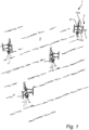
- Fig 1 schematically shows an offshore wind farm 1 including a plurality of wind turbines 3, here in the form of vertical axle wind turbines (VAWTs) according to an example embodiment of the present invention, floating in the sea 5.
- VAWTs vertical axle wind turbines
- These floating VAWTs 3 are shown to each have three blades 7, where each blade 7 is coupled to the wind turbine body 9 using two struts 11a-b.
- the scope of the claims is not limited to this particular type of VAWTs, but additionally encompasses, for example, land-based VAWTs, VAWTs with a smaller or larger number of blades and/or a smaller or larger number of struts per blade.
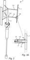
- each of the struts 11a-b has a first end 13a coupled to the wind turbine body 9 and a second end 13b coupled to the blade 7 using a fastening arrangement (in fig 2 , the first and second ends are only indicated by reference numerals for one of the struts 11b to avoid cluttering the drawings).
- Fig 3A is a partial side view, in which the strut 11b is partly opened to reveal an example configuration of the above-mentioned fastening arrangement 15 that is used to couple the second end 13b of the strut 11b to the blade 7.
- the fastening arrangement comprises a pliable fastening member 17 pulling the blade 7 towards the second end 13b of the strut 11b.
- the pliable fastening member 17 is illustrated in the form of a textile sling passing around the entire circumference of the blade 7.
- the pliable fastening member 17 is made of a textile material
- a suitable material that is commercially available.
- polyester such as UHMwPE, and Kevlar, etc.
- the fastening arrangement 15, including the configuration of the contact interface may be configured to provide sufficient friction to prevent relative movement between the blade 7 and the second end 13b of the strut 11b, even when various forces may act together to reduce the contact forces at the contact interface.
- Such forces may include the centrifugal force, wind force, and a component of the gravitational force acting on the blade 7, especially when wind and/or waves cause the VAWT 3 to deviate from a vertical orientation of the wind turbine body 9.
- a pliable fastening member 17 Through the use of a pliable fastening member 17, the substantial force required to prevent relative movement between the blade 7 and the strut 11b can be made to act on a relatively large area, reducing the stress on the blade 7 and/or strut 11b as compared to conventional bolted connections. Furthermore, a pliable fastening member 17 can be made considerably more resilient to fatigue than rigid connections.
- the pulling force represented by the arrow 19 in fig 3A is provided by a tensioning arrangement.
- An example configuration of such a tensioning arrangement will be described below with reference to fig 3B .
- a tensioning arrangement 21 is provided for tensioning the pliable fastening member 17.
- the tensioning arrangement 21 is shown in fig 3B as being attached to the strut 11b at a position 23 spaced apart from the second end 13b of the strut 11b, to allow the tensioning arrangement 21 to provide the above-mentioned pulling force to the pliable fastening member 17.
- the tensioning arrangement 21 for tensioning the pliable fastening member 17 comprises a tensioning actuator 22 in the form of a screw.
- a tensioning actuator 22 in the form of a screw.
- suitable screws are, per se, known, including roller screws, ball screws, lead screws etc.
- other kinds of tensioning actuators may be beneficial depending on the requirements of the particular installation. Examples of such other kinds of tensioning actuators include a hydraulic cylinder, a spring, a bolt, etc.
- the tensioning arrangement 21 could alternatively be arranged in or on the blade 7.
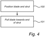
- Fig 4 is a flow-chart schematically illustrating an example embodiment of the method according to the present invention of joining a blade and a strut of a VAWT.
- Figs 5A-B are schematic illustrations of different steps in the flow-chart in fig 4 .
- the blade 7 and the strut 11b are arranged, in step 100, in such a way that a joining surface 25 of the blade 7 faces an end 13b of the strut 11b.
- the VAWT 3 may be provided with a positioning structure configured to define a relative positional arrangement of the blade 7 and the end 13b of the strut 11b.
- the positioning structure is indicated as an area 25 with a number of recesses 27 (only one indicated by a reference numeral in fig 5A ) comprised in the blade 7, and an area 29 with complementary protrusions 31 at the end 13b of the strut 11b.
- the provision of the positioning structure may facilitate relative positioning of the blade 7 and the strut 11b, and may also assist in maintaining the desired relative positioning while applying tension to the pliable fastening member 17, as will be described below with reference to fig 5B .
- the positioning structure will be possible, and may be beneficial depending on various circumstances, such as the material of the blade 7 and/or strut 11b and the method used for manufacturing the blade 7 and/or strut 11b.
- One example of an alternative configuration could be a guiding pin attached to one of the blade 7 and the strut 11b and a corresponding hole arranged to accommodate the guiding pin formed in the other one of the blade 7 and the strut 11b.
- the pliable fastening member 17 is indicated as surrounding the blade 7.
- the pliable fastening member 17 may be installed before or after the positioning of the blade 7 and the strut 11b in relation to each other.
- the blade 7 and the strut 11b may first be arranged adjacent to each other, as shown in fig 5A , and then the pliable fastening member 17 may be pulled around the blade 7 before coupling both ends of the pliable fastening member 17 to the tensioning arrangement 21.
- the pliable fastening member 17 may first be coupled to the tensioning arrangement 21, and then the blade 7 may be inserted in the loop formed by the pliable fastening member 17, or the loop may be moved along the length of the blade 7 to the correct relative position of blade 7 and strut 11b.
- the blade 7 is then pulled, in step 101 towards the end 13b of the strut 11b until the joining surface 25 of the blade 7 is pressed against the end 13b of the strut 11b, by operating the tensioning arrangement 21.
- the tensioning arrangement 21 may be operated until the pliable fastening member 17 has been subjected to a predefined tensile force. This predefined tensile force may, for example, be determined using simulation, and may be selected to ensure none or limited relative movement between the blade 7 and the strut 11b, at the contact interface, when the VAWT 3 is in operation.
- the blade 7 is shown to comprise internal passages 35a-b accommodating the pliable fastening member 17.
- the internal passages 35a-b pass through the blade 7 from the proximal side 37 of the blade 7 facing the wind turbine body 9 (see fig 2 ) to the distal side 39 of the blade 7 facing away from the wind turbine body 9.
- the blade 7 comprises an internal passage 35 with both openings towards the proximal side 37 of the blade 7.
- an end portion of the strut 11b may be provided with side-facing openings 41a-b for the pliable fastening member 17.
Landscapes
- Engineering & Computer Science (AREA)
- General Engineering & Computer Science (AREA)
- Mechanical Engineering (AREA)
- Life Sciences & Earth Sciences (AREA)
- Sustainable Development (AREA)
- Sustainable Energy (AREA)
- Chemical & Material Sciences (AREA)
- Combustion & Propulsion (AREA)
- Wind Motors (AREA)
Claims (8)
- Windturbine (3) mit vertikaler Achse, die Folgendes umfasst:einen Windturbinenkörper (9),eine Schaufel (7) undeine Strebe (11a-b), die ein erstes Ende (13a), das an den Windturbinenkörper gekoppelt ist, und ein zweites Ende (13b), das unter Verwendung einer Befestigungsanordnung (15) an die Schaufel gekoppelt ist, aufweist,wobei die Befestigungsanordnung ein biegsames Befestigungselement (17) umfasst, das die Schaufel (7) hin zu dem zweiten Ende (13b) der Strebe (11a-b) zieht, mit einer Kraft, welche die Schaufel (7) gegen das zweite Ende (13b) der Strebe (11a-b) presst,wobei das biegsame Befestigungselement (17) um zumindest einen Abschnitt der Schaufel (7) herumgeht,wobei die Befestigungsanordnung (15) eine Spannanordnung (21) umfasst, die das biegsame Befestigungselement (17) spannt, undwobei die Spannanordnung (21) an einer Position entlang der Strebe, die von dem zweiten Ende (13b) der Strebe (11a-b) beabstandet ist, an der Strebe (11a-b) befestigt ist.
- Windturbine (3) mit vertikaler Achse nach Anspruch 1, wobei die Schaufel (7) einen inneren Durchgang umfasst, der das biegsame Befestigungselement (17) aufnimmt.
- Windturbine (3) mit vertikaler Achse nach einem der vorhergehenden Ansprüche, wobei das biegsame Befestigungselement (17) zumindest teilweise aus einem textilen Material hergestellt ist.
- Windturbine (3) mit vertikaler Achse nach einem der vorhergehenden Ansprüche, wobei das biegsame Befestigungselement (17) mindestens eine Schlinge umfasst.
- Windturbine (3) mit vertikaler Achse nach einem der vorhergehenden Ansprüche, wobei die Spannanordnung (21) einen spannenden Stellantrieb umfasst.
- Windturbine (3) mit vertikaler Achse nach einem der vorhergehenden Ansprüche, die ferner eine Positionierungsstruktur umfasst, die dafür konfiguriert ist, eine relative Anordnung der Schaufel (7) und des zweiten Endes (13b) der Strebe (11a-b) zu definieren.
- Windturbine (3) mit vertikaler Achse nach Anspruch 6, wobei die Positionierungsstruktur mindestens eine Aussparung (27) in dem einen von der Schaufel und dem zweiten Ende der Strebe und mindestens einen Vorsprung (31) in dem anderen von der Schaufel und dem zweiten Ende der Strebe umfasst, wobei der mindestens eine Vorsprung dafür konfiguriert ist, mit der mindestens einen Aussparung in Wechselwirkung zu treten, um eine relative Bewegung zwischen dem zweiten Ende der Strebe und der Schaufel einzuschränken.
- Verfahren zum Verbinden einer Schaufel (7) und einer Strebe (11a-b) einer Windturbine (3) mit vertikaler Achse, das die folgenden Schritte umfasst:Führen eines biegsamen Befestigungselements (17) um zumindest einen Abschnitt der Schaufel (7),Anordnen der Schaufel (7) und der Strebe (11a-b) auf eine solche Weise, dass eine Verbindungsfläche der Schaufel einem Ende der Strebe gegenüberliegt, undZiehen der Schaufel (7) hin zu dem Ende (13b) der Strebe (11a-b) unter Verwendung des biegsamen Befestigungselements (17), bis die Verbindungsfläche der Schaufel gegen das Ende der Strebe gepresst wird, wobei:die Strebe (11a-b) eine Spannanordnung (21) einschließt, die an einer Position entlang der Strebe, die von dem zweiten Ende der Strebe beabstandet ist, an der Strebe befestigt ist undder Schritt des Ziehens die folgenden Schritte umfasst:Koppeln des biegsamen Befestigungselements (17) an die Spannanordnung (21) undBetätigen der Spannanordnung (21), bis das biegsame Befestigungselement einer vordefinierten Zugkraft ausgesetzt worden ist.
Applications Claiming Priority (2)
| Application Number | Priority Date | Filing Date | Title |
|---|---|---|---|
| SE2051212 | 2020-10-19 | ||
| PCT/SE2021/051013 WO2022086394A1 (en) | 2020-10-19 | 2021-10-14 | Vertical axis wind turbine and method of joining blade and strut |
Publications (4)
| Publication Number | Publication Date |
|---|---|
| EP4200527A1 EP4200527A1 (de) | 2023-06-28 |
| EP4200527A4 EP4200527A4 (de) | 2023-11-22 |
| EP4200527C0 EP4200527C0 (de) | 2025-03-05 |
| EP4200527B1 true EP4200527B1 (de) | 2025-03-05 |
Family
ID=81290869
Family Applications (1)
| Application Number | Title | Priority Date | Filing Date |
|---|---|---|---|
| EP21883404.2A Active EP4200527B1 (de) | 2020-10-19 | 2021-10-14 | Windturbine mit vertikaler achse und verfahren zur verbindung von schaufel und strebe |
Country Status (5)
| Country | Link |
|---|---|
| US (1) | US12044209B2 (de) |
| EP (1) | EP4200527B1 (de) |
| JP (1) | JP7605978B2 (de) |
| CN (1) | CN116490426B (de) |
| WO (1) | WO2022086394A1 (de) |
Families Citing this family (1)
| Publication number | Priority date | Publication date | Assignee | Title |
|---|---|---|---|---|
| JP7605978B2 (ja) * | 2020-10-19 | 2024-12-24 | シートビルル アクティエボラーグ | 垂直軸風力タービンおよびブレードと支柱の結合方法 |
Family Cites Families (30)
| Publication number | Priority date | Publication date | Assignee | Title |
|---|---|---|---|---|
| US148927A (en) * | 1874-03-24 | Improvement in windmills | ||
| US4130380A (en) * | 1976-05-13 | 1978-12-19 | Kaiser Heinz W | Wind powered turbine and airfoil construction |
| US4566854A (en) * | 1984-05-21 | 1986-01-28 | Slezak Ray J | Wind rotor |
| DE3825241A1 (de) * | 1988-04-08 | 1989-10-19 | Bentzel & Herter Wirtschafts U | Windturbine |
| PT102693A (pt) | 2001-11-21 | 2003-05-30 | Fernando Augusto Baptista | Torres eolicas com sistemas de seguranca e de transmissao de forca |
| JP2005061328A (ja) * | 2003-08-13 | 2005-03-10 | Fjc:Kk | 風車の羽根並びに縦軸風車 |
| ITBZ20070021A1 (it) | 2007-05-17 | 2008-11-18 | Ropatec Srl | Braccio di supporto per ali di turbine eoliche ad asse di rotazione verticale |
| GB2461753A (en) * | 2008-07-15 | 2010-01-20 | Univ Nottingham | Bracing Arrangement for Large Horizontal-Axis Wind-Turbine |
| US20100172759A1 (en) | 2009-01-08 | 2010-07-08 | Sullivan John T | Retractable wind turbines |
| JP5448690B2 (ja) * | 2009-10-05 | 2014-03-19 | 古河電気工業株式会社 | 風力発電装置 |
| US20110150652A1 (en) * | 2009-12-22 | 2011-06-23 | Lucid Energy Technologies, Llp | Turbine assemblies |
| US20110311364A1 (en) * | 2010-06-18 | 2011-12-22 | Conner Michael D | Balanced Lift Wind Turbine |
| IT1401811B1 (it) * | 2010-09-07 | 2013-08-28 | Linz Electric S R L | Turbina eolica ad asse verticale |
| CN202055997U (zh) * | 2011-05-10 | 2011-11-30 | 济南磁能科技有限公司 | 一种垂直轴风力机的自动调桨装置 |
| FR2975138B1 (fr) * | 2011-05-12 | 2013-05-17 | Benoit Castagnou | Rotor d'eolienne a axe vertical du type darrieus et eolienne equipee d'un tel rotor |
| KR101561585B1 (ko) * | 2013-05-06 | 2015-10-20 | 이인남 | 발전효율을 증대시킨 날개 가변형 조력 겸용 풍력발전기 |
| FR3007804B1 (fr) * | 2013-07-01 | 2015-06-19 | Geps Innov | Dispositif hybride de production d'energie electrique |
| DE102015012084A1 (de) * | 2015-09-15 | 2017-03-16 | Alexander Degtjarew | Die Luftschraube mit zwei universellen selbstzentrierten Systemen |
| DE102015012083A1 (de) * | 2015-09-15 | 2017-03-16 | Alexander Degtjarew | Die Windturbine. |
| DE102015012086A1 (de) * | 2015-09-15 | 2017-03-16 | Alexander Degtjarew | Die Stütze für die jungen Bäume. |
| DE102015012081A1 (de) * | 2015-09-15 | 2017-03-16 | Alexander Degtjarew | Die Luftschraube. |
| ITUA20163710A1 (it) * | 2016-05-04 | 2017-11-04 | Flaminio Fracaroli | Turbina eolica ad asse verticale con pale mobili |
| JP2018150863A (ja) | 2017-03-13 | 2018-09-27 | Ntn株式会社 | 垂直軸風車および風力発電装置 |
| DE102017006360A1 (de) * | 2017-06-28 | 2019-01-03 | Dietmar Völkner | Anordnung und Verfahren zur Herstellung eines Windgenerators mit fünf senkrechten, beweglichen Rotorblättern. |
| CN211434802U (zh) * | 2017-09-06 | 2020-09-08 | 西安大医集团股份有限公司 | 一种叶片驱动机构及系统 |
| US20190153997A1 (en) | 2017-11-17 | 2019-05-23 | Ecoligent, LLC | System for converting energy from flowing media |
| CN108506161A (zh) * | 2018-03-21 | 2018-09-07 | 四川大学 | 垂直轴风轮和风力发电机 |
| CN113357077B (zh) * | 2020-03-04 | 2024-12-06 | 周济泽 | 双风轮垂直轴风力发电装置 |
| JP7605978B2 (ja) * | 2020-10-19 | 2024-12-24 | シートビルル アクティエボラーグ | 垂直軸風力タービンおよびブレードと支柱の結合方法 |
| DE102020007543B3 (de) * | 2020-12-08 | 2022-03-17 | Friedrich B. Grimm | Windkraftanlage mit einer vertikalen rotationsachse |
-
2021
- 2021-10-14 JP JP2023521856A patent/JP7605978B2/ja active Active
- 2021-10-14 WO PCT/SE2021/051013 patent/WO2022086394A1/en not_active Ceased
- 2021-10-14 CN CN202180069368.1A patent/CN116490426B/zh active Active
- 2021-10-14 US US18/246,890 patent/US12044209B2/en active Active
- 2021-10-14 EP EP21883404.2A patent/EP4200527B1/de active Active
Also Published As
| Publication number | Publication date |
|---|---|
| WO2022086394A1 (en) | 2022-04-28 |
| EP4200527A1 (de) | 2023-06-28 |
| CN116490426A (zh) | 2023-07-25 |
| EP4200527C0 (de) | 2025-03-05 |
| EP4200527A4 (de) | 2023-11-22 |
| JP2023546385A (ja) | 2023-11-02 |
| US12044209B2 (en) | 2024-07-23 |
| US20230366375A1 (en) | 2023-11-16 |
| CN116490426B (zh) | 2026-01-02 |
| JP7605978B2 (ja) | 2024-12-24 |
Similar Documents
| Publication | Publication Date | Title |
|---|---|---|
| AU2021403357B2 (en) | A pitch controlled wind turbine with blade connecting members | |
| EP2288807B1 (de) | Unterteilte schaufel | |
| JP4220547B2 (ja) | ローターブレード接合部 | |
| US12258935B2 (en) | Pitch controlled wind turbine with blade connecting members and split blades | |
| US7993103B2 (en) | Wind turbine blades and methods of attaching such blades to a hub | |
| EP4200527B1 (de) | Windturbine mit vertikaler achse und verfahren zur verbindung von schaufel und strebe | |
| EP4457432B1 (de) | Windenergieanlage | |
| EP4536956A1 (de) | Pitchgeregelte windturbine | |
| US20250065992A1 (en) | Floating wind platform and associated floating wind assembly | |
| EP4536957A1 (de) | Pitchgeregelte windturbine | |
| CN119422002A (zh) | 风力涡轮机叶片系列 | |
| US20220307473A1 (en) | Wind turbine comprising a drag device | |
| US20250067242A1 (en) | Rotor Structure for Fluid Kinetic Power Generation Turbine | |
| WO2018098549A1 (en) | A vertical-axis wind turbine | |
| US20250369418A1 (en) | A wind turbine | |
| WO2023237166A1 (en) | A pitch controlled wind turbine | |
| EP4680854A1 (de) | Pitchgeregelte windturbine | |
| CN120344763A (zh) | 升级改造的风力涡轮机 |
Legal Events
| Date | Code | Title | Description |
|---|---|---|---|
| STAA | Information on the status of an ep patent application or granted ep patent |
Free format text: STATUS: THE INTERNATIONAL PUBLICATION HAS BEEN MADE |
|
| PUAI | Public reference made under article 153(3) epc to a published international application that has entered the european phase |
Free format text: ORIGINAL CODE: 0009012 |
|
| STAA | Information on the status of an ep patent application or granted ep patent |
Free format text: STATUS: REQUEST FOR EXAMINATION WAS MADE |
|
| 17P | Request for examination filed |
Effective date: 20230322 |
|
| AK | Designated contracting states |
Kind code of ref document: A1 Designated state(s): AL AT BE BG CH CY CZ DE DK EE ES FI FR GB GR HR HU IE IS IT LI LT LU LV MC MK MT NL NO PL PT RO RS SE SI SK SM TR |
|
| RIC1 | Information provided on ipc code assigned before grant |
Ipc: F03D 1/06 20060101ALI20231010BHEP Ipc: B63B 35/44 20060101ALI20231010BHEP Ipc: F03D 3/06 20060101AFI20231010BHEP |
|
| A4 | Supplementary search report drawn up and despatched |
Effective date: 20231025 |
|
| RIC1 | Information provided on ipc code assigned before grant |
Ipc: F03D 1/06 20060101ALI20231019BHEP Ipc: B63B 35/44 20060101ALI20231019BHEP Ipc: F03D 3/06 20060101AFI20231019BHEP |
|
| DAV | Request for validation of the european patent (deleted) | ||
| DAX | Request for extension of the european patent (deleted) | ||
| GRAP | Despatch of communication of intention to grant a patent |
Free format text: ORIGINAL CODE: EPIDOSNIGR1 |
|
| STAA | Information on the status of an ep patent application or granted ep patent |
Free format text: STATUS: GRANT OF PATENT IS INTENDED |
|
| INTG | Intention to grant announced |
Effective date: 20241014 |
|
| GRAS | Grant fee paid |
Free format text: ORIGINAL CODE: EPIDOSNIGR3 |
|
| GRAA | (expected) grant |
Free format text: ORIGINAL CODE: 0009210 |
|
| STAA | Information on the status of an ep patent application or granted ep patent |
Free format text: STATUS: THE PATENT HAS BEEN GRANTED |
|
| AK | Designated contracting states |
Kind code of ref document: B1 Designated state(s): AL AT BE BG CH CY CZ DE DK EE ES FI FR GB GR HR HU IE IS IT LI LT LU LV MC MK MT NL NO PL PT RO RS SE SI SK SM TR |
|
| REG | Reference to a national code |
Ref country code: GB Ref legal event code: FG4D |
|
| REG | Reference to a national code |
Ref country code: CH Ref legal event code: EP |
|
| REG | Reference to a national code |
Ref country code: IE Ref legal event code: FG4D |
|
| REG | Reference to a national code |
Ref country code: DE Ref legal event code: R096 Ref document number: 602021027329 Country of ref document: DE |
|
| U01 | Request for unitary effect filed |
Effective date: 20250306 |
|
| U07 | Unitary effect registered |
Designated state(s): AT BE BG DE DK EE FI FR IT LT LU LV MT NL PT RO SE SI Effective date: 20250314 |
|
| PG25 | Lapsed in a contracting state [announced via postgrant information from national office to epo] |
Ref country code: RS Free format text: LAPSE BECAUSE OF FAILURE TO SUBMIT A TRANSLATION OF THE DESCRIPTION OR TO PAY THE FEE WITHIN THE PRESCRIBED TIME-LIMIT Effective date: 20250605 |
|
| PG25 | Lapsed in a contracting state [announced via postgrant information from national office to epo] |
Ref country code: ES Free format text: LAPSE BECAUSE OF FAILURE TO SUBMIT A TRANSLATION OF THE DESCRIPTION OR TO PAY THE FEE WITHIN THE PRESCRIBED TIME-LIMIT Effective date: 20250305 |
|
| PG25 | Lapsed in a contracting state [announced via postgrant information from national office to epo] |
Ref country code: NO Free format text: LAPSE BECAUSE OF FAILURE TO SUBMIT A TRANSLATION OF THE DESCRIPTION OR TO PAY THE FEE WITHIN THE PRESCRIBED TIME-LIMIT Effective date: 20250605 |
|
| PG25 | Lapsed in a contracting state [announced via postgrant information from national office to epo] |
Ref country code: HR Free format text: LAPSE BECAUSE OF FAILURE TO SUBMIT A TRANSLATION OF THE DESCRIPTION OR TO PAY THE FEE WITHIN THE PRESCRIBED TIME-LIMIT Effective date: 20250305 |
|
| PG25 | Lapsed in a contracting state [announced via postgrant information from national office to epo] |
Ref country code: GR Free format text: LAPSE BECAUSE OF FAILURE TO SUBMIT A TRANSLATION OF THE DESCRIPTION OR TO PAY THE FEE WITHIN THE PRESCRIBED TIME-LIMIT Effective date: 20250606 |
|
| PG25 | Lapsed in a contracting state [announced via postgrant information from national office to epo] |
Ref country code: SM Free format text: LAPSE BECAUSE OF FAILURE TO SUBMIT A TRANSLATION OF THE DESCRIPTION OR TO PAY THE FEE WITHIN THE PRESCRIBED TIME-LIMIT Effective date: 20250305 |
|
| PG25 | Lapsed in a contracting state [announced via postgrant information from national office to epo] |
Ref country code: PL Free format text: LAPSE BECAUSE OF FAILURE TO SUBMIT A TRANSLATION OF THE DESCRIPTION OR TO PAY THE FEE WITHIN THE PRESCRIBED TIME-LIMIT Effective date: 20250305 |
|
| PG25 | Lapsed in a contracting state [announced via postgrant information from national office to epo] |
Ref country code: CZ Free format text: LAPSE BECAUSE OF FAILURE TO SUBMIT A TRANSLATION OF THE DESCRIPTION OR TO PAY THE FEE WITHIN THE PRESCRIBED TIME-LIMIT Effective date: 20250305 |
|
| PG25 | Lapsed in a contracting state [announced via postgrant information from national office to epo] |
Ref country code: SK Free format text: LAPSE BECAUSE OF FAILURE TO SUBMIT A TRANSLATION OF THE DESCRIPTION OR TO PAY THE FEE WITHIN THE PRESCRIBED TIME-LIMIT Effective date: 20250305 |
|
| PG25 | Lapsed in a contracting state [announced via postgrant information from national office to epo] |
Ref country code: IS Free format text: LAPSE BECAUSE OF FAILURE TO SUBMIT A TRANSLATION OF THE DESCRIPTION OR TO PAY THE FEE WITHIN THE PRESCRIBED TIME-LIMIT Effective date: 20250705 |
|
| U20 | Renewal fee for the european patent with unitary effect paid |
Year of fee payment: 5 Effective date: 20251006 |
|
| PGFP | Annual fee paid to national office [announced via postgrant information from national office to epo] |
Ref country code: GB Payment date: 20251006 Year of fee payment: 5 |
|
| PLBE | No opposition filed within time limit |
Free format text: ORIGINAL CODE: 0009261 |
|
| STAA | Information on the status of an ep patent application or granted ep patent |
Free format text: STATUS: NO OPPOSITION FILED WITHIN TIME LIMIT |
|
| REG | Reference to a national code |
Ref country code: CH Ref legal event code: L10 Free format text: ST27 STATUS EVENT CODE: U-0-0-L10-L00 (AS PROVIDED BY THE NATIONAL OFFICE) Effective date: 20260114 |
|
| 26N | No opposition filed |
Effective date: 20251208 |