EP4200574B1 - Système et procédés d'échangeur de chaleur à déflecteur de tige verticale - Google Patents
Système et procédés d'échangeur de chaleur à déflecteur de tige verticale Download PDFInfo
- Publication number
- EP4200574B1 EP4200574B1 EP21766460.6A EP21766460A EP4200574B1 EP 4200574 B1 EP4200574 B1 EP 4200574B1 EP 21766460 A EP21766460 A EP 21766460A EP 4200574 B1 EP4200574 B1 EP 4200574B1
- Authority
- EP
- European Patent Office
- Prior art keywords
- rod baffle
- longitudinal partition
- partition plate
- heat exchanger
- rod
- Prior art date
- Legal status (The legal status is an assumption and is not a legal conclusion. Google has not performed a legal analysis and makes no representation as to the accuracy of the status listed.)
- Active
Links
Images


Classifications
-
- F—MECHANICAL ENGINEERING; LIGHTING; HEATING; WEAPONS; BLASTING
- F28—HEAT EXCHANGE IN GENERAL
- F28D—HEAT-EXCHANGE APPARATUS, NOT PROVIDED FOR IN ANOTHER SUBCLASS, IN WHICH THE HEAT-EXCHANGE MEDIA DO NOT COME INTO DIRECT CONTACT
- F28D7/00—Heat-exchange apparatus having stationary tubular conduit assemblies for both heat-exchange media, the media being in contact with different sides of a conduit wall
- F28D7/16—Heat-exchange apparatus having stationary tubular conduit assemblies for both heat-exchange media, the media being in contact with different sides of a conduit wall the conduits being arranged in parallel spaced relation
- F28D7/163—Heat-exchange apparatus having stationary tubular conduit assemblies for both heat-exchange media, the media being in contact with different sides of a conduit wall the conduits being arranged in parallel spaced relation with conduit assemblies having a particular shape, e.g. square or annular; with assemblies of conduits having different geometrical features; with multiple groups of conduits connected in series or parallel and arranged inside common casing
- F28D7/1669—Heat-exchange apparatus having stationary tubular conduit assemblies for both heat-exchange media, the media being in contact with different sides of a conduit wall the conduits being arranged in parallel spaced relation with conduit assemblies having a particular shape, e.g. square or annular; with assemblies of conduits having different geometrical features; with multiple groups of conduits connected in series or parallel and arranged inside common casing the conduit assemblies having an annular shape; the conduits being assembled around a central distribution tube
- F28D7/1676—Heat-exchange apparatus having stationary tubular conduit assemblies for both heat-exchange media, the media being in contact with different sides of a conduit wall the conduits being arranged in parallel spaced relation with conduit assemblies having a particular shape, e.g. square or annular; with assemblies of conduits having different geometrical features; with multiple groups of conduits connected in series or parallel and arranged inside common casing the conduit assemblies having an annular shape; the conduits being assembled around a central distribution tube with particular pattern of flow of the heat exchange media, e.g. change of flow direction
-
- F—MECHANICAL ENGINEERING; LIGHTING; HEATING; WEAPONS; BLASTING
- F28—HEAT EXCHANGE IN GENERAL
- F28D—HEAT-EXCHANGE APPARATUS, NOT PROVIDED FOR IN ANOTHER SUBCLASS, IN WHICH THE HEAT-EXCHANGE MEDIA DO NOT COME INTO DIRECT CONTACT
- F28D7/00—Heat-exchange apparatus having stationary tubular conduit assemblies for both heat-exchange media, the media being in contact with different sides of a conduit wall
- F28D7/06—Heat-exchange apparatus having stationary tubular conduit assemblies for both heat-exchange media, the media being in contact with different sides of a conduit wall the conduits having a single U-bend
-
- F—MECHANICAL ENGINEERING; LIGHTING; HEATING; WEAPONS; BLASTING
- F28—HEAT EXCHANGE IN GENERAL
- F28D—HEAT-EXCHANGE APPARATUS, NOT PROVIDED FOR IN ANOTHER SUBCLASS, IN WHICH THE HEAT-EXCHANGE MEDIA DO NOT COME INTO DIRECT CONTACT
- F28D7/00—Heat-exchange apparatus having stationary tubular conduit assemblies for both heat-exchange media, the media being in contact with different sides of a conduit wall
- F28D7/16—Heat-exchange apparatus having stationary tubular conduit assemblies for both heat-exchange media, the media being in contact with different sides of a conduit wall the conduits being arranged in parallel spaced relation
-
- F—MECHANICAL ENGINEERING; LIGHTING; HEATING; WEAPONS; BLASTING
- F28—HEAT EXCHANGE IN GENERAL
- F28F—DETAILS OF HEAT-EXCHANGE AND HEAT-TRANSFER APPARATUS, OF GENERAL APPLICATION
- F28F9/00—Casings; Header boxes; Auxiliary supports for elements; Auxiliary members within casings
- F28F9/007—Auxiliary supports for elements
- F28F9/013—Auxiliary supports for elements for tubes or tube-assemblies
- F28F9/0135—Auxiliary supports for elements for tubes or tube-assemblies formed by grids having only one tube per closed grid opening
- F28F9/0136—Auxiliary supports for elements for tubes or tube-assemblies formed by grids having only one tube per closed grid opening formed by intersecting strips
-
- F—MECHANICAL ENGINEERING; LIGHTING; HEATING; WEAPONS; BLASTING
- F28—HEAT EXCHANGE IN GENERAL
- F28D—HEAT-EXCHANGE APPARATUS, NOT PROVIDED FOR IN ANOTHER SUBCLASS, IN WHICH THE HEAT-EXCHANGE MEDIA DO NOT COME INTO DIRECT CONTACT
- F28D21/00—Heat-exchange apparatus not covered by any of the groups F28D1/00 - F28D20/00
- F28D2021/0019—Other heat exchangers for particular applications; Heat exchange systems not otherwise provided for
- F28D2021/0059—Other heat exchangers for particular applications; Heat exchange systems not otherwise provided for for petrochemical plants
-
- F—MECHANICAL ENGINEERING; LIGHTING; HEATING; WEAPONS; BLASTING
- F28—HEAT EXCHANGE IN GENERAL
- F28F—DETAILS OF HEAT-EXCHANGE AND HEAT-TRANSFER APPARATUS, OF GENERAL APPLICATION
- F28F9/00—Casings; Header boxes; Auxiliary supports for elements; Auxiliary members within casings
- F28F9/22—Arrangements for directing heat-exchange media into successive compartments, e.g. arrangements of guide plates
- F28F2009/222—Particular guide plates, baffles or deflectors, e.g. having particular orientation relative to an elongated casing or conduit
- F28F2009/224—Longitudinal partitions
-
- F—MECHANICAL ENGINEERING; LIGHTING; HEATING; WEAPONS; BLASTING
- F28—HEAT EXCHANGE IN GENERAL
- F28F—DETAILS OF HEAT-EXCHANGE AND HEAT-TRANSFER APPARATUS, OF GENERAL APPLICATION
- F28F2225/00—Reinforcing means
- F28F2225/04—Reinforcing means for conduits
-
- F—MECHANICAL ENGINEERING; LIGHTING; HEATING; WEAPONS; BLASTING
- F28—HEAT EXCHANGE IN GENERAL
- F28F—DETAILS OF HEAT-EXCHANGE AND HEAT-TRANSFER APPARATUS, OF GENERAL APPLICATION
- F28F2265/00—Safety or protection arrangements; Arrangements for preventing malfunction
- F28F2265/30—Safety or protection arrangements; Arrangements for preventing malfunction for preventing vibrations
Definitions
- Embodiments disclosed herein relate generally to heat exchanger systems. More particularly, embodiments disclosed herein relate to vertical rod baffle heat exchangers for reaction heat removal.
- Rod baffle heat exchangers were created in 1970 by Philips Petroleum Company to eliminate flow-induced vibrations in a plate baffle heat exchanger.
- Rod baffle heat exchangers are shell and tube type heat exchangers utilizing rod baffles to support the tubes and secure them against vibrations. Additionally, rod baffles can be used to correct shell-side flow distributions and to create a more turbulent shell-side flow.
- the term "baffle” refers to an annular ring in which the ends of a plurality of support rods are connected; hence the term "rod baffle”. Examples of rod baffle heat exchangers may be found in, for example, U.S. Patent No. 5,642,778 and Chinese Patent No. 104197751 .
- a conventional rod baffle heat exchanger such as a shell and tube heat exchanger 10 may include a rod baffle tube bundle 12 surrounded by a shell 14. Tubes 28 in the tube bundle 12 are supported by a plurality of rod baffle assemblies 16, 18, 20, and 22.
- One fluid enters the shell-side of the shell and tube heat exchanger 10 through an inlet 26 and after heat exchange with the fluid in tubes 28 leaves the shell-side via outlet 30.
- the fluid flowing through the tube side of the heat exchanger enters the end cap 38 of the heat exchanger via inlet 32 and leaves the end cap 44 of the heat exchanger via outlet 34.
- fluid flows from end chamber 36, which is defined by end cap 38 of the heat exchanger 10 and tube sheet 40, through the tubes 28 and into the opposite end chamber 42, which is similarly defined by the end cap 44 and the other tube sheet 46.
- CN 104 197 751 A describes a vertical baffle heat exchanger comprising a casing, a tube sheet, a heat exchange tube bundle, multiple supporting strips arranged on the periphery for fixing the heat exchange tube bundle, and a plurality of notched longitudinal partitions disposed in the casing. These partitions may have a notch width and a pitch that are adjustable.
- the present disclosure relates to a vertical rod baffle heat exchanger as defined in claim 1.
- Embodiments of the vertical rod baffle heat exchanger may be used for heat removal, condensation operations, electricity generation, petrochemical plants, waste heat recovery, and other industrial applications.
- the vertical rod baffle heat exchanger may further include a plurality of support bars arranged on a circumference of the shell adapted to fix the tube bundle and be a slideway for the plurality of rod baffle rings.
- the plurality of support bars may be spaced apart from each other and rotated in 90-degree increments around a circumference of the plurality of rod baffle rings.
- a non-condensable gas outlet may be provided at a similar level close to the tube-sheet on the shell as a vapor inlet.
- a liquid seal cylindrical section may be provided close to an elbow section on the shell side.
- An impingement plate may be provided in the shell to distribute incoming vapor from the inlet.
- the plurality of rod baffle rings may have a set of four rod baffle rings: a first rod baffle ring having a plurality of lateral rod baffles extending from an inner surface of the first rod baffle ring, a second rod baffle ring having a plurality of longitudinal rod baffles extending from an inner surface of the second rod baffle ring, a third rod baffle ring having a plurality of lateral rod baffles extending from an inner surface of the third rod baffle ring, and a fourth rod baffle ring having a plurality of longitudinal rod baffles extending from an inner surface of the fourth rod baffle ring.
- the vertical rod baffle heat exchanger may include at least four sets of four rod baffle rings.
- a fifth set of four rod baffle rings may include two of the first rod baffle rings, the third rod baffle ring, and the fourth rod baffle ring.
- Each of the plurality of rod baffle rings may be evenly spaced a distance from an adjacent rod baffle across a length of the U-tube bundle.
- Each of the six or more longitudinal partition plates may be a notched longitudinal partition plate. A width of each of the longitudinal partition plates may be between 3 to 9 millimeters.
- a distance between the longitudinal partition plates and a length of the notched longitudinal partition plates may be varied.
- a distance between a first longitudinal partition plate and a second longitudinal partition plate may be greater than a distance between the second longitudinal partition plate and a third longitudinal partition plate.
- the distance between the second longitudinal partition plate and the third longitudinal partition plate may be greater than a distance between the third longitudinal partition plate and a fourth longitudinal partition plate.
- the distance between the third longitudinal partition plate and the fourth longitudinal partition plate may be greater than a distance between the fourth longitudinal partition plate and a fifth longitudinal partition plate.
- the distance between the fourth longitudinal partition plate and the fifth longitudinal partition plate may be greater than a distance between the fifth longitudinal partition plate and a sixth longitudinal partition plate.
- the notched end of each notched longitudinal partition plate may be a vertical distance from the shell. The vertical distance of the notched longitudinal partition plates may progressively decrease from the first longitudinal partition plate to the sixth longitudinal partition plate.
- fluids may refer to slurries, liquids, gases, and/or mixtures thereof.
- like or identical reference numerals are used in the figures to identify common or the same elements.
- the figures are not necessarily to scale, and certain features and certain views of the figures may be shown exaggerated in scale for purposes of clarification.
- rod baffle heat exchanger for heat removal, condensation operations, electricity generation, petrochemical plants, waste heat recovery, and other industrial applications.
- the rod baffle heat exchanger may also be interchangeably referred to as a rod baffle condenser in the present disclosure.
- the rod baffle heat exchanger may incorporate vertical baffles with vertical partition plates.
- the rod baffle heat exchanger may aid in the removal of polymerization heat in a cool loop. Further, the rod baffle heat exchanger may allow for a higher condensation efficiency compared to conventional condensers.
- Conventional rod baffle heat exchangers in industrial applications are typically exceptionally large and heavy due to horizontal arrangement. Additionally, conventional vertical rod baffle heat exchangers use small and shorter longitudinal baffle plates. Conventional vertical rod baffle heat exchangers are not sufficient for the increased size and capacity of modern polymerization reactors. For example, conventional vertical rod baffle heat exchangers, when increased for size and capacity, may cause shutdowns due to too low of a liquid level and subsequently a short cut of vapor flow.
- the rod baffle heat exchanger may increase a gas velocity around tubes in the rod baffle heat exchanger and increase the operational range with regards to heat exchange coefficient.
- Rod baffle heat exchangers may include prolonged baffle plates, allowing lower liquid levels to enlarge the operation range of the polymerization process.
- the prolonged longitudinal baffle plates may reduce a risk of plant shutdowns during unexpected changes in cooling water temperature and allow to operate the plant with higher throughputs.
- the rod baffle arrangement in the heat exchanger provides improved vibration protection by the rod baffles being distributed more evenly. Additionally, the rod baffle heat exchangers may increase reliability and performance over cycles of operation. Overall, the rod baffle heat exchangers may minimize product engineering, risk associated with rod baffle manufacture, reduction of assembly time, hardware cost reduction, and weight and envelope reduction.
- Rod baffle heat exchangers may include a number of longitudinal baffle plates to increase the vapor velocities, making the heat transfer more efficient.
- the rod baffle heat exchanger may have six longitudinal baffle plates.
- support for lateral and longitudinal rods of the rod baffle heat exchanger may be split and distributed more evenly to improve an anti-vibration effect.
- a length of the longitudinal baffle plates may be increased to cover at least a full length of a U-bundle in order to increase an operational flexibility by maintaining a liquid seal even at low levels.
- the rod baffle heat exchanger may be a vertical rod baffle condenser with six or more prolonged longitudinal partition plates.
- the prolonged longitudinal partition plates may allow a higher condensation efficiency in the vertical rod baffle condenser by increasing the gas velocity around the tubes.
- the prolonged longitudinal partition plates may increase the operational range with regards to heat exchange coefficient by the prolonged baffle plates, which allow lower liquid levels.
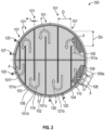
- Figures 2 shows a top view of a rod baffle heat exchanger 100 in accordance with one or more embodiments of the present disclosure.
- the rod baffle heat exchanger 100 includes six or more longitudinal partition plates 101 and a tube bundle 102.
- the six or more longitudinal partition plates 101 are inserted within the tube bundle 102.
- the tube bundle 102 is surrounded by a shell 103.
- a number of instrument nozzles 120 may be placed around the shell 103.
- the instrument nozzles 120 may provide various measurements on the rod baffle heat exchanger 100 such as level measurements, temperature measurements, and other measurements in the rod baffle heat exchanger 100.
- a tube-sheet 119 is provided and may be provided on top of the six or more longitudinal partition plates 101.
- a distance D between the longitudinal partition plates 101 may be varied.
- the distance D between a first longitudinal partition plate 101a and a second longitudinal partition plate 101b may be greater than the distance between the second longitudinal partition plate 101b and a third longitudinal partition plate 101c.
- the distance between the second longitudinal partition plate 101b and the third longitudinal partition plate 101c may be greater than the distance between the third longitudinal partition plate 101c and a fourth longitudinal partition plate 101d.
- the distance between the third longitudinal partition plate 101c and the fourth longitudinal partition plate 101d may be greater than the distance between the fourth longitudinal partition plate 101d and a fifth longitudinal partition plate 101e.
- the distance between the fourth longitudinal partition plate 101d and the fifth longitudinal partition plate 101e may be greater than the distance between the fifth longitudinal partition plate 101e and a sixth longitudinal partition plate 101f. It is further envisioned that a width W of each of the longitudinal partition plates 101 may have a value between 3 to 9 mm, such as 8mm.
- At least one longitudinal partition plate 101 (e.g., one or more of the six or more longitudinal partition plates 101) is a notched longitudinal partition plate 104 provided in the tube bundle 102.
- the at least one longitudinal partition plate 101 has a notched end 105 that has a vertical distance Dn from the shell 103.
- Each of the one or more notched longitudinal partition plates 104 may have such a notched end 105.
- Each of the notched longitudinal partition plates 104 may have varied vertical distances Dn.
- the vertical distance Dn of the notched longitudinal partition plates 104 may progressively decrease from the first longitudinal partition plate 101a to the sixth longitudinal partition plate 101f.
- the vertical distance Dn of the first longitudinal partition plate 101a may be greater than the vertical distance of the second longitudinal partition plate 101b.
- the vertical distance of the second longitudinal partition plate 101b may be greater than the vertical distance of the third longitudinal partition plate 101c.
- the vertical distance of the third longitudinal partition plate 101c may be greater than the vertical distance of the fourth longitudinal partition plate 101d.
- the vertical distance of the fourth longitudinal partition plate 101d may be greater than the vertical distance of the fifth longitudinal partition plate 101e.
- the vertical distance of the fifth longitudinal partition plate 101e may be greater than the vertical distance of the sixth longitudinal partition plate 101f.
- the value of the vertical distance Dn is chosen such that there is enough area between the notched longitudinal partition plates 104 and the shell 103 for a vapor to pass into the next partition.
- adjacent notched longitudinal partition plates 104 may be oriented 180 degrees such that each notched end 105 terminates the adjacent notched longitudinal partition plates 104 in an opposite direction from the shell 103.
- an outlet 107 may be provided at a similar level (circumferential location), close to the tube-sheet 119 on the shell 103, as the inlet 108.
- the outlet 107 may be a non-condensable gas outlet and the inlet 108 may be a vapor inlet in some embodiments.
- vapors may enter the rod baffle heat exchanger 100 and flow through a flow path (see block arrows F) defined by the six or more longitudinal partition plates 101 to exit through the outlet 107.
- a liquid seal cylindrical section 109 may be provided below an elbow section 109a of the rod baffle heat exchanger 100 on the shell 103.
- the elbow section 109a may be a portion of the shell 103 forming the outlet 107 and the inlet 108.
- an impingement plate 110 may be installed in the shell 103 to distribute incoming vapor from the inlet 108.
- a plurality of tubes 106 extend in an axial direction within the tube bundle 102 such that the six or more longitudinal partition plates 101 partition the plurality of tubes 106 of the tube bundle 102.
- the tube bundle 102 is a U-tube bundle such that the plurality of tubes 106 have a bend.
- the notched longitudinal partition plates 104 may extend a length in a radial direction such that the notched end 105 is within the tube bundle 102.
- the radial length of the notched longitudinal partition plates 104 may be measured from an end attached to the shell 103 to the notched end 105.
- a minimum longitudinal length of the notched longitudinal partition plates 104 is greater than a lowest point at which a tube 106 is provided in the U-tube bundle 102.
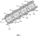
- the rod baffle heat exchanger 100 includes a plurality of rod baffle rings 111, 112, 113, 114 distributed along an axial axis Ax of the plurality of tubes (see 106 in Figure 2 ).
- Figure 3 is shown with four rod baffle rings 111, 112, 113, 114; however, the rod baffle heat exchanger 100 may have any number rod baffle rings without departing from the scope of the present disclosure.
- a plurality of support bars 115 may be arranged on a circumference of the shell (see 103 in Figure 2 ), which may be used to fix the tube bundle (see 102 in Figure 2 ) and function as a slideway for the plurality of rod baffle rings 111, 112, 113, 114.
- the rod baffle heat exchanger 100 may have four support bars 115 evenly spaced such that the support bars 115 may be in 90-degree increments around a circumference of the plurality of rod baffle rings 111, 112, 113, 114.
- the plurality of rod baffle rings 111, 112, 113, 114 may be provided in sets of four.
- the plurality of rod baffle rings 111, 112, 113, 114 may be in a configuration to have each rod baffle ring rotated at 90-degrees from an adjacent rod baffle ring.
- the rod baffle heat exchanger 100 may eliminate a phenomenon of liquid accumulation and realize a high-flux flow of condensate on the plurality of tubes (see 106 in Figure 2 ).
- the first rod baffle ring 111 in the set of four rod baffle rings may have a plurality of lateral rod baffles 111a extending from an inner surface 111b of the first rod baffle ring 111.
- the second rod baffle ring 112 in the set of four rod baffle rings may have a plurality of longitudinal rod baffles 112a extending from an inner surface 112b of the second rod baffle ring 112.
- the third rod baffle ring 113 in the set of four rod baffle rings may have a plurality of lateral rod baffles 113a extending from an inner surface 113b of the third rod baffle ring 113.
- the fourth rod baffle ring 114 in the set of four rod baffle rings may have a plurality of longitudinal rod baffles 114a extending from an inner surface 114b of the fourth rod baffle ring 114.
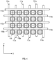
- Figure 4 shows a partial close-up top view of the plurality of tubes 106 being spaced by the lateral rod baffles 111a, 113a of the first and third rod baffle rings 111, 113 and the longitudinal rod baffles 112a, 114a of the second and fourth rod baffle rings 112, 114.
- the lateral rod baffles 111a, 113a pass through a gap 116a between adjacent tubes (106) in the X axis direction.
- the longitudinal rod baffles 112a, 114a pass through a gap 116b between adjacent tubes (106) in the Y axis direction.
- the lateral rod baffles 111a, 113a may also pass through openings in the notched longitudinal partition plates (see 104 in Figure 2 ).
- Figure 5 shows a partial view of the rod baffle heat exchanger 100.
- the plurality of tubes 106 may be in the tube bundle 102 such as a U-tube bundle extending a length L.
- the U-tube bundle 102 allows the plurality of tubes 106 to bend, e.g., U-bend 118, such that full length of the plurality of tubes 106 is greater than the length L of the U-tube bundle 102. This allows the rod baffle heat exchanger 100 to have longer tubes 106 while remaining compact and decrease the overall footprint of the rod baffle heat exchanger 100.
- the inlet 108 is in an upper part on a front side of the tube bundle 102 while the outlet 107 is on a back side of the tube bundle 102. It is further envisioned that the outlet 107 may have a smaller diameter than the inlet 108.
- the rod baffle heat exchanger 100 may have 4 sets of the set of four rod baffle rings 111, 112, 113, 114 as described in Figure 3 such that there are 8 sets of the rod baffle rings with lateral rods and 8 sets of the rod baffle rings with longitudinal rods.
- the rod baffle heat exchanger 100 may include a fifth set of four rod baffle rings configured with two first rod baffle rings such that the order of rod baffle rings is 111, 111, 113, 114, accounting from a U-bend 118 in the U-tube bundle 102. It is further envisioned that a low point of the U-bend 118 may match a lowest rod baffle ring in the rod baffle heat exchanger 100.
- Each of the rod baffle rings 111, 112, 113, 114 may be spaced a distance Drb from an adjacent rod baffle such the rod baffle rings 111, 112, 113, 114 are evenly spaced across the length L of the U-tube bundle. Additionally, each of the rod baffle rings 111, 112, 113, 114 may have a thickness T such that the rod baffle rings have a uniform thickness. It is further envisioned that a rear part 117 of the U-tube bundle may have an anti-vibration grid structure.
Landscapes
- Engineering & Computer Science (AREA)
- Physics & Mathematics (AREA)
- Thermal Sciences (AREA)
- Mechanical Engineering (AREA)
- General Engineering & Computer Science (AREA)
- Geometry (AREA)
- Heat-Exchange Devices With Radiators And Conduit Assemblies (AREA)
- Details Of Heat-Exchange And Heat-Transfer (AREA)
Claims (15)
- Échangeur de chaleur à chicane à tige verticale (100) comprenant :une coque (103) ;une plaque tubulaire (119) ;un faisceau de tubes (102) comportant une pluralité de tubes d'échange thermique (106) s'étendant dans une direction axiale, dans lequel le faisceau de tubes (102) est un faisceau de tubes en U comprenant un coude en U dans la pluralité de tubes d'échange thermique (106) ;six plaques de séparation longitudinales (101) ou plus s'étendant à l'intérieur du faisceau de tubes (102) dans une direction radiale de la coque (103) le long d'une direction longitudinale de la coque (103), dans lequel au moins une plaque de séparation longitudinale (101) est une plaque de séparation longitudinale crantée (104) qui a une extrémité crantée (105) à une distance verticale (Dn) de la coque (103) ; etune pluralité d'anneaux de chicanes à tiges (111, 112, 113, 114) disposés le long d'une longueur axiale de la pluralité de tubes d'échange thermique (106), dans laquelle la pluralité d'anneaux de chicanes à tiges (111, 112, 113, 114) comporte des chicanes latérales (111a, 113a) s'étendant selon un axe X dans la direction radiale et des chicanes longitudinales (112a, 114a) s'étendant selon un axe Y dans la direction radiale,dans lequel les chicanes latérales (111a, 113a) et les chicanes longitudinales (112a, 114a) traversent les espaces (116a, 116b) entre deux tubes adjacents de la pluralité de tubes d'échange thermique (106), et les chicanes latérales (111a, 113a) traversent les ouvertures de la plaque de séparation longitudinale crantée (104), etdans lequel ladite au moins une plaque de séparation longitudinale crantée (104) s'étend sur une longueur minimale dans la direction longitudinale qui est supérieure à un point le plus bas auquel un tube de la pluralité de tubes d'échange thermique (106) est fourni dans le faisceau de tubes en U (102), etdans lequel ladite au moins une plaque de séparation longitudinale crantée (104) s'étend sur une longueur dans la direction radiale de sorte que l'extrémité crantée (105) soit à l'intérieur du faisceau de tubes (102).
- Échangeur de chaleur à chicane à tige verticale (100) selon la revendication 1, comprenant en outre une pluralité de barres de support (115) disposées sur une circonférence de la coque (103), adaptées pour fixer le faisceau de tubes (102) et constituer une glissière pour la pluralité d'anneaux de chicanes à tiges (111, 112, 113, 114).
- Échangeur de chaleur à chicane à tige verticale (100) selon la revendication 2, dans lequel la pluralité de barres de support (115) sont espacées les unes des autres et tournent par incréments de 90 degrés autour d'une circonférence de la pluralité d'anneaux de chicanes à tiges (111, 112, 113, 114).
- Échangeur de chaleur à chicane à tige verticale (100) selon la revendication 1, comprenant en outre une sortie de gaz non condensable (107) située à un niveau similaire à proximité de la plaque tubulaire (119) sur la coque (103) comme entrée de vapeur (108).
- Échangeur de chaleur à chicane à tige verticale (100) selon la revendication 4, comprenant en outre une section cylindrique d'étanchéité au liquide (109) située à proximité d'une section coudée (109a) du côté de la coque.
- Échangeur de chaleur à chicane à tige verticale (100) selon la revendication 4, comprenant en outre une plaque d'impact (110) prévue dans la coque (103) pour distribuer la vapeur entrante à partir de l'entrée de vapeur (108).
- Échangeur de chaleur à chicane à tige verticale (100) selon la revendication 1, dans lequel la pluralité d'anneaux de chicanes à tiges (111, 112, 113, 114) comprend un ensemble de quatre anneaux de chicanes à tiges :un premier anneau de chicane à tige (111) comportant une pluralité de chicanes latérales (111a) s'étendant à partir d'une surface intérieure du premier anneau de chicane à tige (111),un deuxième anneau de chicane à tige (112) comportant une pluralité de chicanes longitudinales (112a) s'étendant à partir d'une surface intérieure du deuxième anneau de chicane à tige (112),un troisième anneau de chicane à tige (113) comportant une pluralité de chicanes latérales (113a) s'étendant à partir d'une surface intérieure du troisième anneau de chicane à tige (113), etun quatrième anneau de chicane à tige (114) comportant une pluralité de chicanes longitudinales (114a) s'étendant à partir d'une surface intérieure du quatrième anneau de chicane à tige (114).
- Échangeur de chaleur à chicane à tige verticale (100) selon la revendication 7, comprenant en outre au moins quatre ensembles de quatre anneaux de chicanes à tiges (111, 112, 113, 114).
- Échangeur de chaleur à chicane à tige verticale (100) selon la revendication 8, comprenant en outre un cinquième ensemble de quatre anneaux de chicanes à tiges comprenant deux des premiers anneaux de chicanes à tiges, le troisième anneau de chicane à tige et le quatrième anneau de chicane à tige.
- Échangeur de chaleur à chicane à tige verticale (100) selon la revendication 1, dans lequel chacun de la pluralité d'anneaux de chicanes à tiges (111, 112, 113, 114) est régulièrement espacé d'une distance d'une chicane à tige adjacente sur toute une longueur du faisceau de tubes en U.
- Échangeur de chaleur à chicane à tige verticale (100) selon la revendication 1, dans lequel chacune des six plaques de séparation longitudinales (101) ou plus est une plaque de séparation longitudinale crantée (104).
- Échangeur de chaleur à chicane à tige verticale (100) selon la revendication 1, dans lequel une largeur de chacune de chacune des plaques de séparation longitudinales (101) est comprise entre 3 et 9 millimètres.
- Échangeur de chaleur à chicane à tige verticale (100) selon la revendication 1, dans lequel une distance entre les plaques de séparation longitudinales (101) et une longueur de ladite au moins une plaque de séparation longitudinale crantée (104) sont modifiées.
- Échangeur de chaleur à chicane à tige verticale (100) selon la revendication 13, dans lequel :une distance entre une première plaque de séparation longitudinale (101a) et une deuxième plaque de séparation longitudinale (101b) est supérieure à une distance entre la deuxième plaque de séparation longitudinale (101b) et une troisième plaque de séparation longitudinale (101c),la distance entre la deuxième plaque de séparation longitudinale (101b) et la troisième plaque de séparation longitudinale (101c) est supérieure à une distance entre la troisième plaque de séparation longitudinale (101c) et une quatrième plaque de séparation longitudinale (101d),la distance entre la troisième plaque de séparation longitudinale (101c) et la quatrième plaque de séparation longitudinale (101d) est supérieure à une distance entre la quatrième plaque de séparation longitudinale (101d) et une cinquième plaque de séparation longitudinale (101e), etla distance entre la quatrième plaque de séparation longitudinale (101d) et la cinquième plaque de séparation longitudinale (101e) est supérieure à une distance entre la cinquième plaque de séparation longitudinale (101e) et une sixième plaque de séparation longitudinale (101f).
- Échangeur de chaleur à chicane à tige verticale (100) selon la revendication 14, dans lequel l'extrémité crantée (105) de chaque plaque de séparation longitudinale crantée (104) est à une distance verticale de la coque (103), la distance verticale des plaques de séparation longitudinales crantées (104) diminuant progressivement de la première plaque de séparation longitudinale (101a) à la sixième plaque de séparation longitudinale (101f).
Applications Claiming Priority (2)
| Application Number | Priority Date | Filing Date | Title |
|---|---|---|---|
| EP20192268.9A EP3957942A1 (fr) | 2020-08-21 | 2020-08-21 | Système et procédés d'échangeur de chaleur à déflecteur de tige verticale |
| PCT/EP2021/073308 WO2022038300A1 (fr) | 2020-08-21 | 2021-08-23 | Système et procédés d'échangeur de chaleur à chicanes à tiges verticales |
Publications (3)
| Publication Number | Publication Date |
|---|---|
| EP4200574A1 EP4200574A1 (fr) | 2023-06-28 |
| EP4200574C0 EP4200574C0 (fr) | 2025-04-23 |
| EP4200574B1 true EP4200574B1 (fr) | 2025-04-23 |
Family
ID=72193404
Family Applications (2)
| Application Number | Title | Priority Date | Filing Date |
|---|---|---|---|
| EP20192268.9A Withdrawn EP3957942A1 (fr) | 2020-08-21 | 2020-08-21 | Système et procédés d'échangeur de chaleur à déflecteur de tige verticale |
| EP21766460.6A Active EP4200574B1 (fr) | 2020-08-21 | 2021-08-23 | Système et procédés d'échangeur de chaleur à déflecteur de tige verticale |
Family Applications Before (1)
| Application Number | Title | Priority Date | Filing Date |
|---|---|---|---|
| EP20192268.9A Withdrawn EP3957942A1 (fr) | 2020-08-21 | 2020-08-21 | Système et procédés d'échangeur de chaleur à déflecteur de tige verticale |
Country Status (10)
| Country | Link |
|---|---|
| US (1) | US20230314086A1 (fr) |
| EP (2) | EP3957942A1 (fr) |
| JP (1) | JP7671342B2 (fr) |
| CN (1) | CN116157643A (fr) |
| BR (1) | BR112023002941A2 (fr) |
| CO (1) | CO2023002179A2 (fr) |
| ES (1) | ES3031585T3 (fr) |
| SA (1) | SA523442600B1 (fr) |
| WO (1) | WO2022038300A1 (fr) |
| ZA (1) | ZA202301863B (fr) |
Families Citing this family (6)
| Publication number | Priority date | Publication date | Assignee | Title |
|---|---|---|---|---|
| CN114636342B (zh) * | 2022-03-02 | 2026-02-06 | 贵州兰鑫石墨机电设备制造有限公司 | 一种设置有笼式可抽拉折流圈组的石墨换热器 |
| CN115854749A (zh) * | 2023-02-20 | 2023-03-28 | 四川荣创新能动力系统有限公司 | 一种燃料电池余热利用换热器 |
| CN117288004A (zh) * | 2023-10-08 | 2023-12-26 | 北京广厦环能科技股份有限公司 | 立式固定管板换热器 |
| CN118912977B (zh) * | 2024-07-30 | 2025-01-28 | 广东西南石化装备有限公司 | 一种换热器 |
| CN119617922A (zh) * | 2024-12-18 | 2025-03-14 | 湖北长江石化设备有限公司 | 一种石油化工用高效换热器 |
| CN120160463B (zh) * | 2025-03-13 | 2025-09-05 | 山东金天和纸业有限公司 | 一种真空透平机的热回收装置 |
Family Cites Families (111)
| Publication number | Priority date | Publication date | Assignee | Title |
|---|---|---|---|---|
| US1848741A (en) * | 1932-03-08 | Heat exchanger baffle construction | ||
| US1790828A (en) * | 1931-02-03 | Heating apparatus | ||
| US1683236A (en) * | 1926-08-31 | 1928-09-04 | Carl F Braun | Heat-exchanging apparatus |
| US1672650A (en) * | 1927-07-27 | 1928-06-05 | Foster Wheeler Corp | Heat exchanger |
| US1813234A (en) * | 1928-03-24 | 1931-07-07 | Gerald D Dodd | Method and apparatus for exchanging heat |
| US1948550A (en) * | 1932-07-23 | 1934-02-27 | Joseph T Voorheis | Oil heater |
| US1962362A (en) * | 1933-02-28 | 1934-06-12 | Lummus Co | Two pass heat exchanger |
| US2229344A (en) * | 1938-11-19 | 1941-01-21 | Robert Schwarz | Countercurrent heat exchanger |
| US3180405A (en) * | 1959-03-11 | 1965-04-27 | Itt | Condensers |
| US3007679A (en) * | 1960-06-22 | 1961-11-07 | Westinghouse Electric Corp | Anti-vibration structure for heat exchanger tubes |
| DE1235962B (de) * | 1964-01-24 | 1967-03-09 | Babcock & Wilcox Dampfkessel | Rohrdistanzierung fuer Waermetauscher |
| CH428814A (de) * | 1965-01-21 | 1967-01-31 | Sulzer Ag | Abstützung für ein Bündel quer angeströmter Rohre eines Wärmeübertragers |
| GB1081498A (en) * | 1965-02-08 | 1967-08-31 | Rosenblads Patenter Ab | Tubular heat exchangers |
| US3420297A (en) * | 1967-04-25 | 1969-01-07 | Combustion Eng | Heat exchanger tube support and spacing structure |
| FR1539837A (fr) * | 1967-07-31 | 1968-09-20 | Alcatel S A Soc | Procédé de suppression des vibrations dans les tubes et dispositif anti vibratoiremettant en oeuvre ce procédé |
| US3820594A (en) * | 1972-12-15 | 1974-06-28 | Westinghouse Electric Corp | Tube support system for heat exchanger |
| NO132704C (fr) * | 1973-04-10 | 1975-12-17 | Norsk Hydro As | |
| GB1429336A (en) * | 1973-05-15 | 1976-03-24 | Shell Int Research | Heat exchanger and process for cooling hot gases |
| DE2337791C2 (de) * | 1973-07-25 | 1978-07-13 | Siemens Ag, 1000 Berlin Und 8000 Muenchen | Dampferzeuger |
| US3958630A (en) * | 1975-01-24 | 1976-05-25 | Exxon Research And Engineering Company | Heat exchanger baffle arrangement |
| US3998268A (en) * | 1975-03-04 | 1976-12-21 | Westinghouse Electric Corporation | Locking device for staggered fin-tubes |
| US3967677A (en) * | 1975-05-28 | 1976-07-06 | Mobil Oil Corporation | Heat exchanger baffles |
| US4049048A (en) * | 1975-12-19 | 1977-09-20 | Borg-Warner Corporation | Finned tube bundle heat exchanger |
| US4828021A (en) * | 1976-04-29 | 1989-05-09 | Phillips Petroleum Company | Heat exchanger baffle |
| US4136736A (en) * | 1976-04-29 | 1979-01-30 | Phillips Petroleum Company | Baffle |
| CA1067483A (fr) * | 1976-04-29 | 1979-12-04 | Phillips Petroleum Company | Chicanes |
| US4127165A (en) * | 1976-07-06 | 1978-11-28 | Phillips Petroleum Company | Angular rod baffle |
| US4105065A (en) * | 1977-03-07 | 1978-08-08 | Ecodyne Corporation | Heat exchanger |
| US4143709A (en) * | 1977-03-15 | 1979-03-13 | Westinghouse Electric Corp. | Tube support system |
| US4230527A (en) * | 1977-04-29 | 1980-10-28 | Alexander Cella | Steam generator for use in nuclear power plants |
| US4286366A (en) * | 1977-12-23 | 1981-09-01 | Phillips Petroleum Company | Method for the construction of a baffled heat exchanger |
| US4204570A (en) * | 1978-02-23 | 1980-05-27 | Foster Wheeler Energy Corporation | Helical spacer for heat exchanger tube bundle |
| US4253516A (en) * | 1978-06-22 | 1981-03-03 | Westinghouse Electric Corp. | Modular heat exchanger |
| JPS556692U (fr) * | 1978-06-28 | 1980-01-17 | ||
| US4413394A (en) * | 1979-11-29 | 1983-11-08 | Phillips Petroleum Company | Method of constructing a tube bundle |
| US4429739A (en) * | 1980-08-29 | 1984-02-07 | Phillips Petroleum Company | Heat exchanger |
| US4441550A (en) * | 1983-01-14 | 1984-04-10 | Struthers Wells Corporation | Cross-over bundle for heat exchanger |
| US4858681A (en) * | 1983-03-28 | 1989-08-22 | Tui Industries | Shell and tube heat exchanger |
| US4579304A (en) * | 1983-06-01 | 1986-04-01 | Williams George J | Tube bundle support |
| US4595161A (en) * | 1983-06-01 | 1986-06-17 | Williams George J | Tube bundle support |
| US4796695A (en) * | 1983-06-30 | 1989-01-10 | Phillips Petroleum Company | Tube supports |
| JPS6060492A (ja) * | 1983-09-14 | 1985-04-08 | Mitsubishi Heavy Ind Ltd | 熱交換器 |
| US4732585A (en) * | 1984-01-09 | 1988-03-22 | Lerner Bernard J | Fluid treating for removal of components or for transfer of heat, momentum-apparatus and method |
| US4640342A (en) * | 1984-01-26 | 1987-02-03 | Westinghouse Electric Corp. | Expandable antivibration bar for heat transfer tubes of a pressurized water reactor steam generator |
| US4789028A (en) * | 1984-11-13 | 1988-12-06 | Westinghouse Electric Corp. | Anti-vibration bars for nuclear steam generators |
| US4720840A (en) * | 1985-06-18 | 1988-01-19 | Westinghouse Electric Corp. | Compliant antivibration bar for a steam generator |
| US4823866A (en) * | 1987-11-09 | 1989-04-25 | Phillips Petroleum Company | Tube support for heat exchanger |
| CS269165B1 (cs) * | 1988-04-15 | 1990-04-11 | Jan Ing Nemcansky | Výměník tepla |
| US4893671A (en) * | 1988-06-20 | 1990-01-16 | Westinghouse Electric Corp. | Steam generator tube antivibration apparatus and method |
| JPH0730213Y2 (ja) * | 1988-11-17 | 1995-07-12 | 川崎重工業株式会社 | 熱交換器 |
| JPH02109188U (fr) * | 1989-02-20 | 1990-08-30 | ||
| DE3906241A1 (de) * | 1989-02-28 | 1990-08-30 | Mtu Muenchen Gmbh | Waermetauscher mit einer rohrmatrix |
| DD284517A5 (de) * | 1989-06-01 | 1990-11-14 | Veb Schwermaschinenbau "Karl Liebknecht" Magdeburg,Dd | Rohrbuendelwaermeuebertrager mit schwimmkopf |
| US4972903A (en) * | 1990-01-25 | 1990-11-27 | Phillips Petroleum Company | Heat exchanger |
| CA2036494C (fr) * | 1990-05-11 | 1995-06-27 | Tai W. Kwok | Echange de chaleur pour procede d'alkylation |
| EP0559191A1 (fr) * | 1992-03-05 | 1993-09-08 | Phillips Petroleum Company | Echangeur de chaleur à enveloppe et tubes avec deux passages et tiges-écran support |
| US5323849A (en) * | 1993-04-21 | 1994-06-28 | The United States Of America As Represented By The Secretary Of The Navy | Corrosion resistant shell and tube heat exchanger and a method of repairing the same |
| FR2709174B1 (fr) * | 1993-08-20 | 1995-11-17 | Framatome Sa | Echangeur de chaleur comportant des moyens de maintien de barres antivibratoires intercalés entre les tubes du faisceau de l'échangeur. |
| US5291944A (en) * | 1993-11-25 | 1994-03-08 | Delio Sanz | Heat exchanger |
| US5355945A (en) * | 1993-11-25 | 1994-10-18 | Delio Sanz | Heat exchanger and method of fabrication |
| US5615738A (en) * | 1994-06-29 | 1997-04-01 | Cecebe Technologies Inc. | Internal bypass valve for a heat exchanger |
| JP3424355B2 (ja) * | 1994-11-22 | 2003-07-07 | ダイキン工業株式会社 | 横形シェルアンドチューブ式凝縮器 |
| US5832991A (en) * | 1995-12-29 | 1998-11-10 | Cesaroni; Joseph Anthony | Tube and shell heat exchanger with baffle |
| US6116041A (en) * | 1996-03-15 | 2000-09-12 | Southern Refrigeration Group Pty. Ltd. | Beverage chiller |
| US5642778A (en) | 1996-04-09 | 1997-07-01 | Phillips Petroleum Company | Rod baffle heat exchangers |
| US6059022A (en) * | 1997-02-14 | 2000-05-09 | Westinghouse Electric Company Llc | Steam generation with tube support |
| GB9820712D0 (en) * | 1998-09-24 | 1998-11-18 | Btr Industries Ltd | Heat exchanger |
| US6808017B1 (en) * | 1999-10-05 | 2004-10-26 | Joseph Kaellis | Heat exchanger |
| JP4570168B2 (ja) * | 2003-08-06 | 2010-10-27 | シエル・インターナシヨネイル・リサーチ・マーチヤツピイ・ベー・ウイ | 展伸金属 |
| US6827138B1 (en) * | 2003-08-20 | 2004-12-07 | Abb Lummus Global Inc. | Heat exchanger |
| AU2004304015B2 (en) * | 2003-12-22 | 2008-04-17 | Brembana & Rolle S.P.A. | Support for a tube bundle |
| US7093649B2 (en) * | 2004-02-10 | 2006-08-22 | Peter Dawson | Flat heat exchanger plate and bulk material heat exchanger using the same |
| US7635456B2 (en) * | 2006-08-08 | 2009-12-22 | Kellogg Brown & Root Llc | Low pressure drop reforming reactor |
| EP2118611B1 (fr) * | 2006-12-14 | 2013-04-17 | Embaffle B.V. | Ensemble de déflecteurs et de joints d'étanchéité |
| CN101042289A (zh) * | 2007-04-26 | 2007-09-26 | 宋小平 | 防短路螺旋折流板管壳式换热器拉杆的设置方式 |
| KR100798701B1 (ko) * | 2007-05-29 | 2008-01-28 | 서동숭 | 유압기계 작동오일의 조립형 오일냉각기 |
| JP2010528253A (ja) * | 2007-05-31 | 2010-08-19 | シエル・インターナシヨネイル・リサーチ・マーチヤツピイ・ベー・ウイ | 熱交換器シェルアセンブリ及び組立て方法 |
| US20090242181A1 (en) * | 2008-03-27 | 2009-10-01 | Exxonmobil Research And Engineering Company Law Department | Reduced vibration tube bundle support device |
| US20100116478A1 (en) * | 2008-11-12 | 2010-05-13 | Exxonmobil Research And Engineering Company | Displaceable baffle for a heat exchanger and method for reducing vibration for the same |
| DE102010011644A1 (de) * | 2010-03-16 | 2011-09-22 | Babcock Borsig Service Gmbh | Halteelement und Spacerebene eines Rohrbündels |
| EP2469215B1 (fr) * | 2010-12-21 | 2015-05-06 | Rinheat OY | Echangeur de chaleur à tube |
| US9951997B2 (en) * | 2011-02-04 | 2018-04-24 | Lockheed Martin Corporation | Staged graphite foam heat exchangers |
| US9534779B2 (en) * | 2011-04-04 | 2017-01-03 | Westinghouse Electric Company Llc | Steam generator tube lane flow buffer |
| US20140262172A1 (en) * | 2013-03-14 | 2014-09-18 | Koch Heat Transfer Company, Lp | Tube bundle for shell-and-tube heat exchanger and a method of use |
| US20160061441A1 (en) * | 2013-04-25 | 2016-03-03 | Mitsubishi Heavy Industries, Ltd. | Vibration suppression member for heat transfer tube and its manufacturing method, vibration suppression device and method for heat transfer tube, and steam generator |
| US10401878B2 (en) * | 2013-05-09 | 2019-09-03 | Terydon, Inc. | Indexer, indexer retrofit kit and method of use thereof |
| FR3008779B1 (fr) * | 2013-07-19 | 2018-01-26 | Areva Np | Barre antivibratoire pour faisceau de tubes d'un generateur de vapeur |
| CN103673683B (zh) * | 2013-12-30 | 2016-04-13 | 张家港市江南锅炉压力容器有限公司 | 一种多壳程循环气冷凝器 |
| EP2975353A1 (fr) * | 2014-07-16 | 2016-01-20 | Casale SA | Échangeur thermique à faisceau tubulaire |
| US20160018168A1 (en) * | 2014-07-21 | 2016-01-21 | Nicholas F. Urbanski | Angled Tube Fins to Support Shell Side Flow |
| CN104197751B (zh) | 2014-08-13 | 2016-03-02 | 中国寰球工程公司 | 一种带纵向隔板立式折流杆换热器 |
| US10295266B2 (en) * | 2015-07-14 | 2019-05-21 | Holtec International | Tubular heat exchanger having multiple shell-side and tube-side fluid passes |
| DK3415852T3 (da) * | 2016-08-05 | 2024-02-05 | Obshestvo S Ogranichennoi Otvetstvennostu Reinnolts Lab | Skal- og rørkondensator og varmevekslingsrør til en skal- og rørkondensator (varianter) |
| CN106767039A (zh) * | 2016-12-15 | 2017-05-31 | 佛山科学技术学院 | 折流栅支撑凹面管管束换热器 |
| US10371422B2 (en) * | 2017-02-13 | 2019-08-06 | Daikin Applied Americas Inc. | Condenser with tube support structure |
| EP3364141A1 (fr) * | 2017-02-15 | 2018-08-22 | Casale Sa | Appareil à faisceau tubulaire muni de chicanes |
| CN107883803B (zh) * | 2017-11-06 | 2019-10-15 | 深圳中广核工程设计有限公司 | 管壳式换热器 |
| CN108007255A (zh) * | 2017-12-14 | 2018-05-08 | 佛山科学技术学院 | 一种折流栅支撑轴向凹槽换热管的管壳式换热器 |
| CN108458605A (zh) * | 2018-04-13 | 2018-08-28 | 山东佳能科技股份有限公司 | 内置分布套筒式高效热交换器 |
| CN208765541U (zh) * | 2018-08-23 | 2019-04-19 | 宁波中科远东催化工程技术有限公司 | U型管式换热器 |
| CN209623126U (zh) * | 2019-01-28 | 2019-11-12 | 东方电气集团东方锅炉股份有限公司 | 一种用于槽式光热电站的油盐换热器 |
| US11287196B2 (en) * | 2019-05-31 | 2022-03-29 | Lummus Technology Llc | Helically baffled heat exchanger |
| NL2023898B1 (en) * | 2019-09-25 | 2021-05-25 | Tanis Confectionery B V | a device and method for heating a liquid confectionery product |
| CN110595234B (zh) * | 2019-09-30 | 2024-08-16 | 郑州大学 | 一种多u形换热管的纵流壳程式换热器 |
| DE102019126535A1 (de) * | 2019-10-01 | 2021-04-01 | Bitzer Kühlmaschinenbau Gmbh | Wärmeübertrager, Kälte- oder Wärmeanlage mit einem solchen Wärmeübertrager |
| CN114981610A (zh) * | 2020-01-14 | 2022-08-30 | 科氏传热有限合伙公司 | 用于热交换器的seg-lok挡板 |
| KR102292395B1 (ko) * | 2020-02-13 | 2021-08-20 | 엘지전자 주식회사 | 증발기 |
| EP3957941A1 (fr) * | 2020-08-21 | 2022-02-23 | Yara International ASA | Déflecteurs pour échangeurs de chaleur |
| WO2023004272A1 (fr) * | 2021-07-17 | 2023-01-26 | Lindain Engineering, Inc. | Ensembles déflecteur et support de grille destinés à être utilisés dans des échangeurs de chaleur, et échangeurs de chaleur dotés de tels ensembles |
| US11898682B2 (en) * | 2021-10-15 | 2024-02-13 | General Electric Company | System for spacing and fastening tubular structures |
| IT202200026157A1 (it) * | 2022-12-21 | 2024-06-21 | Giovanni Manenti | Generatore di vapore verticale |
-
2020
- 2020-08-21 EP EP20192268.9A patent/EP3957942A1/fr not_active Withdrawn
-
2021
- 2021-08-23 BR BR112023002941A patent/BR112023002941A2/pt unknown
- 2021-08-23 JP JP2023512425A patent/JP7671342B2/ja active Active
- 2021-08-23 US US18/041,670 patent/US20230314086A1/en active Pending
- 2021-08-23 WO PCT/EP2021/073308 patent/WO2022038300A1/fr not_active Ceased
- 2021-08-23 CN CN202180051376.3A patent/CN116157643A/zh active Pending
- 2021-08-23 EP EP21766460.6A patent/EP4200574B1/fr active Active
- 2021-08-23 ES ES21766460T patent/ES3031585T3/es active Active
-
2023
- 2023-02-15 ZA ZA2023/01863A patent/ZA202301863B/en unknown
- 2023-02-21 SA SA523442600A patent/SA523442600B1/ar unknown
- 2023-02-27 CO CONC2023/0002179A patent/CO2023002179A2/es unknown
Also Published As
| Publication number | Publication date |
|---|---|
| ES3031585T3 (en) | 2025-07-09 |
| JP7671342B2 (ja) | 2025-05-01 |
| EP4200574A1 (fr) | 2023-06-28 |
| SA523442600B1 (ar) | 2025-06-17 |
| WO2022038300A1 (fr) | 2022-02-24 |
| US20230314086A1 (en) | 2023-10-05 |
| CN116157643A (zh) | 2023-05-23 |
| EP4200574C0 (fr) | 2025-04-23 |
| ZA202301863B (en) | 2023-10-25 |
| BR112023002941A2 (pt) | 2023-03-21 |
| JP2023539177A (ja) | 2023-09-13 |
| CO2023002179A2 (es) | 2023-06-09 |
| EP3957942A1 (fr) | 2022-02-23 |
Similar Documents
| Publication | Publication Date | Title |
|---|---|---|
| EP4200574B1 (fr) | Système et procédés d'échangeur de chaleur à déflecteur de tige verticale | |
| CA2726121C (fr) | Echangeur thermique vertical combine entre alimentation et evacuation, avec angle variable des chicanes | |
| US9671173B2 (en) | Re-direction of vapor flow across tubular condensers | |
| WO2012085337A1 (fr) | Enceinte et échangeur de chaleur à tubes | |
| US20200393123A1 (en) | Helical Baffle for Once-Through Steam Generator | |
| US20090242181A1 (en) | Reduced vibration tube bundle support device | |
| EP4374126B1 (fr) | Ensembles déflecteur et support de grille destinés à être utilisés dans des échangeurs de chaleur, et échangeurs de chaleur dotés de tels ensembles | |
| US20240210116A1 (en) | Vertical vapor generator | |
| EP3214389B1 (fr) | Condenseur en série à vide poussé | |
| US20170307300A1 (en) | Re-direction of vapor flow across tubular condensers | |
| US12233363B2 (en) | Vapor distribution system in a concentric reboiler | |
| CA2532466C (fr) | Echangeur de chaleur a faisceau tubulaire | |
| EA046189B1 (ru) | Вертикальный теплообменник со стержневыми перегородками | |
| CN111442657A (zh) | 一种低压真空冷凝器 | |
| JP5938243B2 (ja) | 塔頂凝縮器 |
Legal Events
| Date | Code | Title | Description |
|---|---|---|---|
| STAA | Information on the status of an ep patent application or granted ep patent |
Free format text: STATUS: UNKNOWN |
|
| STAA | Information on the status of an ep patent application or granted ep patent |
Free format text: STATUS: THE INTERNATIONAL PUBLICATION HAS BEEN MADE |
|
| PUAI | Public reference made under article 153(3) epc to a published international application that has entered the european phase |
Free format text: ORIGINAL CODE: 0009012 |
|
| STAA | Information on the status of an ep patent application or granted ep patent |
Free format text: STATUS: REQUEST FOR EXAMINATION WAS MADE |
|
| 17P | Request for examination filed |
Effective date: 20230310 |
|
| AK | Designated contracting states |
Kind code of ref document: A1 Designated state(s): AL AT BE BG CH CY CZ DE DK EE ES FI FR GB GR HR HU IE IS IT LI LT LU LV MC MK MT NL NO PL PT RO RS SE SI SK SM TR |
|
| DAV | Request for validation of the european patent (deleted) | ||
| DAX | Request for extension of the european patent (deleted) | ||
| GRAP | Despatch of communication of intention to grant a patent |
Free format text: ORIGINAL CODE: EPIDOSNIGR1 |
|
| STAA | Information on the status of an ep patent application or granted ep patent |
Free format text: STATUS: GRANT OF PATENT IS INTENDED |
|
| INTG | Intention to grant announced |
Effective date: 20241114 |
|
| RAP3 | Party data changed (applicant data changed or rights of an application transferred) |
Owner name: LUMMUS NOVOLEN TECHNOLOGY GMBH |
|
| GRAS | Grant fee paid |
Free format text: ORIGINAL CODE: EPIDOSNIGR3 |
|
| GRAA | (expected) grant |
Free format text: ORIGINAL CODE: 0009210 |
|
| STAA | Information on the status of an ep patent application or granted ep patent |
Free format text: STATUS: THE PATENT HAS BEEN GRANTED |
|
| AK | Designated contracting states |
Kind code of ref document: B1 Designated state(s): AL AT BE BG CH CY CZ DE DK EE ES FI FR GB GR HR HU IE IS IT LI LT LU LV MC MK MT NL NO PL PT RO RS SE SI SK SM TR |
|
| REG | Reference to a national code |
Ref country code: GB Ref legal event code: FG4D |
|
| REG | Reference to a national code |
Ref country code: CH Ref legal event code: EP |
|
| REG | Reference to a national code |
Ref country code: DE Ref legal event code: R096 Ref document number: 602021029656 Country of ref document: DE |
|
| REG | Reference to a national code |
Ref country code: IE Ref legal event code: FG4D |
|
| U01 | Request for unitary effect filed |
Effective date: 20250507 |
|
| U07 | Unitary effect registered |
Designated state(s): AT BE BG DE DK EE FI FR IT LT LU LV MT NL PT RO SE SI Effective date: 20250514 |
|
| REG | Reference to a national code |
Ref country code: ES Ref legal event code: FG2A Ref document number: 3031585 Country of ref document: ES Kind code of ref document: T3 Effective date: 20250709 |
|
| U20 | Renewal fee for the european patent with unitary effect paid |
Year of fee payment: 5 Effective date: 20250709 |
|
| PG25 | Lapsed in a contracting state [announced via postgrant information from national office to epo] |
Ref country code: GR Free format text: LAPSE BECAUSE OF FAILURE TO SUBMIT A TRANSLATION OF THE DESCRIPTION OR TO PAY THE FEE WITHIN THE PRESCRIBED TIME-LIMIT Effective date: 20250724 |
|
| PG25 | Lapsed in a contracting state [announced via postgrant information from national office to epo] |
Ref country code: PL Free format text: LAPSE BECAUSE OF FAILURE TO SUBMIT A TRANSLATION OF THE DESCRIPTION OR TO PAY THE FEE WITHIN THE PRESCRIBED TIME-LIMIT Effective date: 20250423 |
|
| PG25 | Lapsed in a contracting state [announced via postgrant information from national office to epo] |
Ref country code: HR Free format text: LAPSE BECAUSE OF FAILURE TO SUBMIT A TRANSLATION OF THE DESCRIPTION OR TO PAY THE FEE WITHIN THE PRESCRIBED TIME-LIMIT Effective date: 20250423 |
|
| PG25 | Lapsed in a contracting state [announced via postgrant information from national office to epo] |
Ref country code: RS Free format text: LAPSE BECAUSE OF FAILURE TO SUBMIT A TRANSLATION OF THE DESCRIPTION OR TO PAY THE FEE WITHIN THE PRESCRIBED TIME-LIMIT Effective date: 20250723 |
|
| PG25 | Lapsed in a contracting state [announced via postgrant information from national office to epo] |
Ref country code: IS Free format text: LAPSE BECAUSE OF FAILURE TO SUBMIT A TRANSLATION OF THE DESCRIPTION OR TO PAY THE FEE WITHIN THE PRESCRIBED TIME-LIMIT Effective date: 20250823 |
|
| PGFP | Annual fee paid to national office [announced via postgrant information from national office to epo] |
Ref country code: NO Payment date: 20251008 Year of fee payment: 5 |
|
| PG25 | Lapsed in a contracting state [announced via postgrant information from national office to epo] |
Ref country code: SM Free format text: LAPSE BECAUSE OF FAILURE TO SUBMIT A TRANSLATION OF THE DESCRIPTION OR TO PAY THE FEE WITHIN THE PRESCRIBED TIME-LIMIT Effective date: 20250423 |
|
| PG25 | Lapsed in a contracting state [announced via postgrant information from national office to epo] |
Ref country code: CZ Free format text: LAPSE BECAUSE OF FAILURE TO SUBMIT A TRANSLATION OF THE DESCRIPTION OR TO PAY THE FEE WITHIN THE PRESCRIBED TIME-LIMIT Effective date: 20250423 |
|
| PG25 | Lapsed in a contracting state [announced via postgrant information from national office to epo] |
Ref country code: SK Free format text: LAPSE BECAUSE OF FAILURE TO SUBMIT A TRANSLATION OF THE DESCRIPTION OR TO PAY THE FEE WITHIN THE PRESCRIBED TIME-LIMIT Effective date: 20250423 |
|
| PGFP | Annual fee paid to national office [announced via postgrant information from national office to epo] |
Ref country code: ES Payment date: 20251002 Year of fee payment: 5 |
|
| PLBE | No opposition filed within time limit |
Free format text: ORIGINAL CODE: 0009261 |
|
| STAA | Information on the status of an ep patent application or granted ep patent |
Free format text: STATUS: NO OPPOSITION FILED WITHIN TIME LIMIT |
|
| REG | Reference to a national code |
Ref country code: CH Ref legal event code: L10 Free format text: ST27 STATUS EVENT CODE: U-0-0-L10-L00 (AS PROVIDED BY THE NATIONAL OFFICE) Effective date: 20260304 |
|
| REG | Reference to a national code |
Ref country code: CH Ref legal event code: H13 Free format text: ST27 STATUS EVENT CODE: U-0-0-H10-H13 (AS PROVIDED BY THE NATIONAL OFFICE) Effective date: 20260324 |
|
| PG25 | Lapsed in a contracting state [announced via postgrant information from national office to epo] |
Ref country code: MC Free format text: LAPSE BECAUSE OF FAILURE TO SUBMIT A TRANSLATION OF THE DESCRIPTION OR TO PAY THE FEE WITHIN THE PRESCRIBED TIME-LIMIT Effective date: 20250423 |
|
| 26N | No opposition filed |
Effective date: 20260126 |
|
| PG25 | Lapsed in a contracting state [announced via postgrant information from national office to epo] |
Ref country code: CH Free format text: LAPSE BECAUSE OF NON-PAYMENT OF DUE FEES Effective date: 20250831 |