EP4201176A1 - Système et procédé de réglage de lignes de balayage pour un véhicule de travail - Google Patents
Système et procédé de réglage de lignes de balayage pour un véhicule de travail Download PDFInfo
- Publication number
- EP4201176A1 EP4201176A1 EP22213075.9A EP22213075A EP4201176A1 EP 4201176 A1 EP4201176 A1 EP 4201176A1 EP 22213075 A EP22213075 A EP 22213075A EP 4201176 A1 EP4201176 A1 EP 4201176A1
- Authority
- EP
- European Patent Office
- Prior art keywords
- work vehicle
- computing system
- vehicle
- swath line
- swath
- Prior art date
- Legal status (The legal status is an assumption and is not a legal conclusion. Google has not performed a legal analysis and makes no representation as to the accuracy of the status listed.)
- Withdrawn
Links
- 238000000034 method Methods 0.000 title claims description 35
- 230000008859 change Effects 0.000 claims description 12
- 238000005516 engineering process Methods 0.000 description 8
- 230000000712 assembly Effects 0.000 description 5
- 238000000429 assembly Methods 0.000 description 5
- 230000005540 biological transmission Effects 0.000 description 5
- 238000010586 diagram Methods 0.000 description 4
- 230000006870 function Effects 0.000 description 4
- 239000002689 soil Substances 0.000 description 3
- 238000010276 construction Methods 0.000 description 2
- 238000012986 modification Methods 0.000 description 2
- 230000004048 modification Effects 0.000 description 2
- 230000003287 optical effect Effects 0.000 description 2
- 230000005355 Hall effect Effects 0.000 description 1
- 241001124569 Lycaenidae Species 0.000 description 1
- 241000699670 Mus sp. Species 0.000 description 1
- 238000009313 farming Methods 0.000 description 1
- 238000005096 rolling process Methods 0.000 description 1
- 238000003860 storage Methods 0.000 description 1
- 238000003971 tillage Methods 0.000 description 1
- 230000007704 transition Effects 0.000 description 1
Images

Classifications
-
- B—PERFORMING OPERATIONS; TRANSPORTING
- B60—VEHICLES IN GENERAL
- B60W—CONJOINT CONTROL OF VEHICLE SUB-UNITS OF DIFFERENT TYPE OR DIFFERENT FUNCTION; CONTROL SYSTEMS SPECIALLY ADAPTED FOR HYBRID VEHICLES; ROAD VEHICLE DRIVE CONTROL SYSTEMS FOR PURPOSES NOT RELATED TO THE CONTROL OF A PARTICULAR SUB-UNIT
- B60W30/00—Purposes of road vehicle drive control systems not related to the control of a particular sub-unit, e.g. of systems using conjoint control of vehicle sub-units
- B60W30/18—Propelling the vehicle
-
- A—HUMAN NECESSITIES
- A01—AGRICULTURE; FORESTRY; ANIMAL HUSBANDRY; HUNTING; TRAPPING; FISHING
- A01B—SOIL WORKING IN AGRICULTURE OR FORESTRY; PARTS, DETAILS, OR ACCESSORIES OF AGRICULTURAL MACHINES OR IMPLEMENTS, IN GENERAL
- A01B69/00—Steering of agricultural machines or implements; Guiding agricultural machines or implements on a desired track
- A01B69/007—Steering or guiding of agricultural vehicles, e.g. steering of the tractor to keep the plough in the furrow
-
- A—HUMAN NECESSITIES
- A01—AGRICULTURE; FORESTRY; ANIMAL HUSBANDRY; HUNTING; TRAPPING; FISHING
- A01B—SOIL WORKING IN AGRICULTURE OR FORESTRY; PARTS, DETAILS, OR ACCESSORIES OF AGRICULTURAL MACHINES OR IMPLEMENTS, IN GENERAL
- A01B69/00—Steering of agricultural machines or implements; Guiding agricultural machines or implements on a desired track
- A01B69/003—Steering or guiding of machines or implements pushed or pulled by or mounted on agricultural vehicles such as tractors, e.g. by lateral shifting of the towing connection
- A01B69/004—Steering or guiding of machines or implements pushed or pulled by or mounted on agricultural vehicles such as tractors, e.g. by lateral shifting of the towing connection automatic
-
- B—PERFORMING OPERATIONS; TRANSPORTING
- B60—VEHICLES IN GENERAL
- B60W—CONJOINT CONTROL OF VEHICLE SUB-UNITS OF DIFFERENT TYPE OR DIFFERENT FUNCTION; CONTROL SYSTEMS SPECIALLY ADAPTED FOR HYBRID VEHICLES; ROAD VEHICLE DRIVE CONTROL SYSTEMS FOR PURPOSES NOT RELATED TO THE CONTROL OF A PARTICULAR SUB-UNIT
- B60W10/00—Conjoint control of vehicle sub-units of different type or different function
- B60W10/04—Conjoint control of vehicle sub-units of different type or different function including control of propulsion units
- B60W10/06—Conjoint control of vehicle sub-units of different type or different function including control of propulsion units including control of combustion engines
-
- B—PERFORMING OPERATIONS; TRANSPORTING
- B60—VEHICLES IN GENERAL
- B60W—CONJOINT CONTROL OF VEHICLE SUB-UNITS OF DIFFERENT TYPE OR DIFFERENT FUNCTION; CONTROL SYSTEMS SPECIALLY ADAPTED FOR HYBRID VEHICLES; ROAD VEHICLE DRIVE CONTROL SYSTEMS FOR PURPOSES NOT RELATED TO THE CONTROL OF A PARTICULAR SUB-UNIT
- B60W10/00—Conjoint control of vehicle sub-units of different type or different function
- B60W10/10—Conjoint control of vehicle sub-units of different type or different function including control of change-speed gearings
-
- B—PERFORMING OPERATIONS; TRANSPORTING
- B60—VEHICLES IN GENERAL
- B60W—CONJOINT CONTROL OF VEHICLE SUB-UNITS OF DIFFERENT TYPE OR DIFFERENT FUNCTION; CONTROL SYSTEMS SPECIALLY ADAPTED FOR HYBRID VEHICLES; ROAD VEHICLE DRIVE CONTROL SYSTEMS FOR PURPOSES NOT RELATED TO THE CONTROL OF A PARTICULAR SUB-UNIT
- B60W10/00—Conjoint control of vehicle sub-units of different type or different function
- B60W10/18—Conjoint control of vehicle sub-units of different type or different function including control of braking systems
- B60W10/184—Conjoint control of vehicle sub-units of different type or different function including control of braking systems with wheel brakes
-
- B—PERFORMING OPERATIONS; TRANSPORTING
- B60—VEHICLES IN GENERAL
- B60W—CONJOINT CONTROL OF VEHICLE SUB-UNITS OF DIFFERENT TYPE OR DIFFERENT FUNCTION; CONTROL SYSTEMS SPECIALLY ADAPTED FOR HYBRID VEHICLES; ROAD VEHICLE DRIVE CONTROL SYSTEMS FOR PURPOSES NOT RELATED TO THE CONTROL OF A PARTICULAR SUB-UNIT
- B60W10/00—Conjoint control of vehicle sub-units of different type or different function
- B60W10/20—Conjoint control of vehicle sub-units of different type or different function including control of steering systems
-
- G—PHYSICS
- G05—CONTROLLING; REGULATING
- G05D—SYSTEMS FOR CONTROLLING OR REGULATING NON-ELECTRIC VARIABLES
- G05D1/00—Control of position, course, altitude or attitude of land, water, air or space vehicles, e.g. using automatic pilots
- G05D1/02—Control of position or course in two dimensions
- G05D1/021—Control of position or course in two dimensions specially adapted to land vehicles
- G05D1/0212—Control of position or course in two dimensions specially adapted to land vehicles with means for defining a desired trajectory
- G05D1/0219—Control of position or course in two dimensions specially adapted to land vehicles with means for defining a desired trajectory ensuring the processing of the whole working surface
-
- G—PHYSICS
- G05—CONTROLLING; REGULATING
- G05D—SYSTEMS FOR CONTROLLING OR REGULATING NON-ELECTRIC VARIABLES
- G05D1/00—Control of position, course, altitude or attitude of land, water, air or space vehicles, e.g. using automatic pilots
- G05D1/60—Intended control result
- G05D1/648—Performing a task within a working area or space, e.g. cleaning
-
- B—PERFORMING OPERATIONS; TRANSPORTING
- B60—VEHICLES IN GENERAL
- B60W—CONJOINT CONTROL OF VEHICLE SUB-UNITS OF DIFFERENT TYPE OR DIFFERENT FUNCTION; CONTROL SYSTEMS SPECIALLY ADAPTED FOR HYBRID VEHICLES; ROAD VEHICLE DRIVE CONTROL SYSTEMS FOR PURPOSES NOT RELATED TO THE CONTROL OF A PARTICULAR SUB-UNIT
- B60W2300/00—Indexing codes relating to the type of vehicle
- B60W2300/15—Agricultural vehicles
-
- B—PERFORMING OPERATIONS; TRANSPORTING
- B60—VEHICLES IN GENERAL
- B60W—CONJOINT CONTROL OF VEHICLE SUB-UNITS OF DIFFERENT TYPE OR DIFFERENT FUNCTION; CONTROL SYSTEMS SPECIALLY ADAPTED FOR HYBRID VEHICLES; ROAD VEHICLE DRIVE CONTROL SYSTEMS FOR PURPOSES NOT RELATED TO THE CONTROL OF A PARTICULAR SUB-UNIT
- B60W2300/00—Indexing codes relating to the type of vehicle
- B60W2300/17—Construction vehicles, e.g. graders, excavators
-
- B—PERFORMING OPERATIONS; TRANSPORTING
- B60—VEHICLES IN GENERAL
- B60W—CONJOINT CONTROL OF VEHICLE SUB-UNITS OF DIFFERENT TYPE OR DIFFERENT FUNCTION; CONTROL SYSTEMS SPECIALLY ADAPTED FOR HYBRID VEHICLES; ROAD VEHICLE DRIVE CONTROL SYSTEMS FOR PURPOSES NOT RELATED TO THE CONTROL OF A PARTICULAR SUB-UNIT
- B60W2300/00—Indexing codes relating to the type of vehicle
- B60W2300/44—Tracked vehicles
Definitions
- the present disclosure generally relates to work vehicles, such as agricultural vehicles or construction vehicles, and, more particularly, to systems and methods for generating swath lines for a work vehicle.
- the present subject matter is directed to a work vehicle.
- the work vehicle includes a frame configured to support a plurality of components of the work vehicle.
- the work vehicle includes a sensor configured to capture data indicative of an operating parameter of the work vehicle and a computing system communicatively coupled to the sensor.
- the computing system is configured to access a swath line corresponding to a pass to be made across a field by the work vehicle.
- the computing system is configured to control an operation of the plurality of components such that the work vehicle travels along the swath line to make the pass across the field.
- the computing system is configured to determine the operating parameter of the work vehicle based on the data captured by the sensor as the work vehicle travels along the swath line.
- the computing system is configured to adjust a portion of the swath line positioned forward of the work vehicle relative to a direction of travel of the work vehicle based on the determined operating parameter as the work vehicle travels along the swath line.
- the present subject matter is directed to a system for adjusting swath lines for a work vehicle.
- the system includes a sensor configured to capture data indicative of an operating parameter of the work vehicle and a computing system communicatively coupled to the sensor.
- the computing system is configured to access a swath line corresponding to a pass to be made across a field by the work vehicle.
- the computing system is configured to control an operation of the work vehicle such that the work vehicle travels along the swath line to make the pass across the field.
- the computing system is configured to determine the operating parameter of the work vehicle based on the data captured by the sensor as the work vehicle travels along the swath line.
- the computing system is configured to adjust a portion of the swath line positioned forward of the work vehicle relative to a direction of travel of the work vehicle based on the determined operating parameter as the work vehicle travels along the swath line.
- the present subject matter is directed to a method for adjusting swath lines for a work vehicle.
- the method includes accessing, with a computing system, a swath line corresponding to a pass to be made across a field by the work vehicle. Furthermore, the method includes controlling, with the computing system, an operation of the work vehicle such that the work vehicle travels along the swath line to make the pass across the field. Additionally, the method includes receiving, with the computing system, sensor data indicative of an operating parameter of the work vehicle. Moreover, the method includes determining, with the computing system, the operating parameter of the work vehicle based on the received sensor data as the work vehicle travels along the swath line.
- the method includes adjusting, with the computing system, a portion of the swath line positioned forward of the work vehicle relative to a direction of travel of the work vehicle based on the determined operating parameter as the work vehicle travels along the swath line.
- the present subject matter is directed to a system and a method for adjusting swath lines for a work vehicle.
- the work vehicle includes one or more operating parameter sensors.
- Each operating parameter sensor is configured to capture data indicative of an operating parameter of the work vehicle.
- the operating parameter(s) may include a vehicle dynamics parameter(s), such as a turning radius of the vehicle, a slew rate of vehicle and an associated implement, and/or a slip of the vehicle.
- the operating parameter(s) may include a loading parameter(s) of the vehicle.
- a computing system of the disclosed system is configured to adjust a swath line being used to guide the work vehicle across a field based on one or more operating parameters of the vehicle.
- the computing system is configured to access a swath line corresponding to a pass to be made across a field by the vehicle.
- the computing system may access a swath line that was generated during a previous operation on the field.
- the computing system is configured to control the operation of the work vehicle such that the work vehicle travels along the accessed swath line to make the pass across the field.
- the computing system is configured to receive the data captured by the operating parameter sensor(s) and determine the operating parameter(s) of the work vehicle based on the received data. Thereafter, as the work vehicle travels along the swath line, the computing system is configured to adjust a portion of the swath line positioned forward of the work vehicle based on the determined operating parameter(s).
- Adjusting a swath line used to guide a work vehicle across a field based on an operating parameter(s) of the vehicle determined as the vehicle travels across the field improves the operation of the vehicle. More specifically, as a work vehicle travels across a field, field conditions and/or its loading may affect its performance. As such, in certain instances, the vehicle may be unable to follow the swath line being used to guide the vehicle. For example, the minimum turning radius of a vehicle may be greater in muddy field conditions than in dry field conditions.
- the disclosed system and method ensure that the work vehicle can traverse the swath line as field conditions vary.
- the same field conditions may affect different vehicles differently.
- the turning radius of one work vehicle may be more impacted by the same muddy conditions than another work vehicle.
- differing vehicle loading may cause the same field conditions to affect a vehicle differently.
- the disclosed system and method ensure different work vehicles and vehicles of varying loads can traverse the swath line.
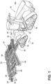
- FIG. 1 illustrates a perspective view of a work vehicle 10 towing an associated agricultural implement 12 across a field in a direction of travel (indicated by arrow 14).
- the work vehicle 10 is configured as an agricultural vehicle (e.g., an agricultural tractor) and the agricultural implement 12 is configured as a tillage implement (e.g., a disk ripper).
- an agricultural vehicle e.g., an agricultural tractor
- a tillage implement e.g., a disk ripper
- the work vehicle 10 may correspond to any other suitable type of agricultural vehicle (e.g., an agricultural harvester, a self-propelled sprayer, etc.) or construction vehicle (e.g., a dozer, a grader, a loader, etc.) and the agricultural implement 12 may correspond to any other suitable type of agricultural implement (e.g., a seed-planting implement, a towable sprayer, etc.). Additionally, in some embodiments, the vehicle 10 may not be configured to tow an implement.
- suitable type of agricultural vehicle e.g., an agricultural harvester, a self-propelled sprayer, etc.
- construction vehicle e.g., a dozer, a grader, a loader, etc.
- the agricultural implement 12 may correspond to any other suitable type of agricultural implement (e.g., a seed-planting implement, a towable sprayer, etc.).
- the vehicle 10 may not be configured to tow an implement.
- the vehicle 10 includes a pair of front track assemblies 16, a pair of rear track assemblies 18, and a frame or chassis 20 coupled to and supported by the track assemblies 16, 18.
- An operator's cab 22 may be supported by a portion of the chassis 20 and may house various input devices for permitting an operator to control the operation of one or more components of the vehicle 10 and/or one or more components of the implement 12.
- the vehicle 10 may include an engine 102 and a transmission 104 mounted on the chassis 20.
- the transmission 104 may be operably coupled to the engine 102 and may provide variably adjusted gear ratios for transferring engine power to the track assemblies 16, 18 via a drive axle assembly (not shown) (or via axles if multiple drive axles are employed).
- the implement 12 includes a frame 24.
- the frame 24 generally includes a plurality of structural frame members 26, such as beams, bars, and/or the like, which are configured to support or couple to a plurality of components.
- the frame 24 may be configured to support one or more ground-engaging tools configured to perform an agricultural operation on a field as the implement 12 travels across the field.
- a hitch assembly 28 may be connected to the frame 24 and configured to couple the implement 12 to the vehicle 10.
- the frame 24 may support one or more gangs or sets of disk blades 30.
- Each disk blade 30 may, in turn, be configured to penetrate into or otherwise engage the soil as the implement 12 is pulled through the field.
- the various gangs of disk blades 30 may be oriented at an angle relative to the direction of travel 14 to promote more effective tilling of the soil.
- the implement 12 includes four gangs of disk blades 30 supported on the frame 24 adjacent to its forward end.
- the implement 12 may include any other suitable number of gangs.
- the gangs of disk blades 30 may be mounted to the frame 24 at any other suitable location, such as adjacent to its aft end.
- the implement frame 24 may be configured to support other ground-engaging tools.
- the frame 24 is configured to support a plurality of shanks 32.
- the shanks 32 are spaced apart from each other on the frame 24 in a lateral direction of the implement 12.
- the lateral direction extends perpendicular to the direction of travel 14.
- the shanks 32 are configured to rip or otherwise till the soil as the implement 12 is towed across the field.
- the frame 24 is also configured to support a plurality of leveling blades 34 and a plurality of rolling (or crumbler) basket assemblies 36 positioned aft of the shanks 32.
- the leveling blades 34 may be spaced apart from each other in the lateral direction.
- any other suitable ground-engaging tools may be coupled to and supported by the implement frame 24.
- the configuration of the work vehicle 10 and the associated agricultural implement 12 described above and shown in FIG. 1 is provided only to place the present subject matter in an exemplary field of use.
- the present subject matter may be readily adaptable to any manner of work vehicle and/or implement configuration.
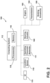
- FIG. 2 a schematic view of one embodiment of a system 100 for adjusting swath lines for a work vehicle is illustrated in accordance with aspects of the present subject matter.
- the system 100 will be described herein with reference to the work vehicle 10 and the agricultural implement 12 described above with reference to FIG. 1 .
- the disclosed system 100 may generally be used with work vehicles having any other suitable vehicle configuration and/or agricultural implements having any other suitable implement configuration.
- the system 100 includes one or more components of the work vehicle 10.
- the system 100 includes the engine 102 and the transmission 104 of the work vehicle 10.
- the system 100 includes one or more braking actuators 106 of the vehicle 10.
- the braking actuator(s) 106 may reduce the speed at which the vehicle/implement 10/12 moves across the field, such as by converting energy associated with the movement of the vehicle/implement 10/12 into heat.
- the braking actuator(s) 106 may correspond to a suitable hydraulic cylinder(s) configured to push a stationary frictional element(s) (not shown), such as a brake shoe(s) or a brake caliper(s), against a rotating element(s) (not shown), such as a brake drum(s) or a brake disk(s).
- a stationary frictional element(s) such as a brake shoe(s) or a brake caliper(s
- the braking actuator(s) 106 may any other suitable hydraulic, pneumatic, mechanical, and/or electrical component(s) configured to convert the rotation of the rotating element(s) into heat.
- the system 100 may include a steering actuator 108 of the work vehicle 10.
- the steering actuator 108 is configured to adjust the direction of travel 14 of the work vehicle 10.
- the steering actuator 108 may correspond to an electric motor, an electric linear actuator, a hydraulic cylinder, a pneumatic cylinder, or any other suitable actuator coupled to suitable mechanical assembly, such as a rack and pinion or a worm gear assembly.
- the system 100 includes a location sensor 110 may be provided in operative association with the work vehicle 10 and/or the implement 12.
- the location sensor 110 may be configured to determine or otherwise capture data indicative of the current location of the work vehicle 10 and/or the associated implement 12 using a satellite navigation positioning system (e.g., a GPS system, a Galileo positioning system, the Global Navigation satellite system (GLONASS), the BeiDou Satellite Navigation and Positioning system, and/or the like).
- the location data captured by the location sensor 110 may be transmitted to a computing system of the work vehicle 10 and/or the implement 12 (e.g., in the form coordinates) and stored within the computing system's memory for subsequent processing and/or analysis.
- the location data received from the location sensor 110 may be used to geo-locate the vehicle 10 within the field, thereby allowing for recording of the travel path of the vehicle/implement 10/12 across the field.
- each operating parameter sensor 111 is configured to capture data indicative of an operating parameter of the vehicle 10 and/or the associated implement 12. As will be described below, the data captured by the operating parameter sensor(s) 111 is used to adjust at least a portion of a swath line being used to guide the work vehicle 10 across the field to ensure the vehicle 10 can travel along the swath line despite varying field conditions.
- the operating parameter sensor(s) 111 may be configured to capture data indicative of a vehicle dynamics parameter(s).
- the operating parameter sensor(s) 111 may be configured to capture data indicative of the turning radius of the vehicle 10 (e.g., its maximum wheel angle).
- the operating parameter sensor(s) 111 may be configured to capture data indicative of the slew rate of the vehicle/implement 10/12 combination. The slew rate, in turn, corresponds to turning rate of the vehicle 10 and the associated implement 12 combination and defines the transition from a straight path to the desired turning radius.
- the operating parameter sensor(s) 111 may be configured to capture data indicative of the lateral slip of the vehicle 10 and the implement 12.
- the operating parameter sensor(s) 111 may be configured to capture data indicative of other types of slip, such as understeer and/or oversteer of the vehicle 10 and/or the implement 12.
- the operating parameter sensor(s) 111 may correspond to any suitable sensor(s) or sensing device(s) configured to capture data indicative of the above parameter(s), such as a potentiometer(s), a Hall effect sensor(s), an accelerometer(s), an IMU(s), and/or the like.
- the operating parameter sensor(s) may be configured to capture data indicative of any other suitable vehicle dynamics parameter(s) in addition to or in lieu of above-described vehicle dynamics parameters.
- the operating parameter sensor(s) 111 may be configured to capture data indicative of a vehicle loading parameter(s).
- the operating parameter sensor(s) 111 may be configured to capture data indicative of the total weight of the vehicle 10 and/or implement 12, the weight on the front axle (not shown) of the vehicle 10, or any other suitable weight/loading parameter(s).
- the operating parameter sensor(s) 111 may correspond to any suitable sensor(s) or sensing device(s) configured to capture data indicative of the above parameter(s), such as a strain gauge(s), a load cell(s), and/or the like.
- the operating parameter sensor(s) may be configured to capture data indicative of any other suitable vehicle loading parameter(s) or other operating parameter(s) in addition to or in lieu of above-described parameters.
- the system 100 includes a computing system 112 communicatively coupled to one or more components of the work vehicle 10, the implement 12, and/or the system 100 to allow the operation of such components to be electronically or automatically controlled by the computing system 112.
- the computing system 112 may be communicatively coupled to the sensors 110 via a communicative link 114.
- the computing system 112 may be configured to receive data (e.g., coordinates) from the location sensor 110 that is indicative of the location of the vehicle/implement 10/12 within the field.
- the computing system 112 may be communicatively coupled to the operating parameter sensor(s) 111 via the communicative link 114.
- the computing system 112 may be configured to receive data from the operating parameter sensor(s) 111 that is indicative of one or more operating parameters of the vehicle 10 and/or implement 12. Furthermore, the computing system 112 may be communicatively coupled to various components of the vehicle 10, such as the engine 102, the transmission 104, the braking actuator(s) 106, and/or the steering actuator 108, via the communicative link 114. In this respect, the computing system 112 may be configured to control the operation of such components 102, 104, 106, 108 to the operation of the vehicle/implement 10/12 (e.g., its direction of travel 14, ground speed, etc.). In addition, the computing system 112 may be communicatively coupled to any other suitable components of the vehicle 10, the implement 12, and/or the system 100.
- the computing system 112 may be communicatively coupled to any other suitable components of the vehicle 10, the implement 12, and/or the system 100.
- the computing system 112 may comprise one or more processor-based devices, such as a given controller or computing device or any suitable combination of controllers or computing devices.
- the computing system 112 may include one or more processor(s) 116 and associated memory device(s) 118 configured to perform a variety of computer-implemented functions.
- processor refers not only to integrated circuits referred to in the art as being included in a computer, but also refers to a controller, a microcontroller, a microcomputer, a programmable logic circuit (PLC), an application specific integrated circuit, and other programmable circuits.
- the memory device(s) 118 of the computing system 112 may generally comprise memory element(s) including, but not limited to, a computer readable medium (e.g., random access memory RAM)), a computer readable non-volatile medium (e.g., a flash memory), a floppy disk, a compact disk-read only memory (CD-ROM), a magneto-optical disk (MOD), a digital versatile disk (DVD) and/or other suitable memory elements.
- Such memory device(s) 118 may generally be configured to store suitable computer-readable instructions that, when implemented by the processor(s) 116, configure the computing system 112 to perform various computer-implemented functions, such as one or more aspects of the methods and algorithms that will be described herein.
- the computing system 112 may also include various other suitable components, such as a communications circuit or module, one or more input/output channels, a data/control bus and/or the like.
- the various functions of the computing system 112 may be performed by a single processor-based device or may be distributed across any number of processor-based devices, in which instance such devices may be considered to form part of the computing system 112.
- the functions of the computing system 112 may be distributed across multiple application-specific controllers or computing devices, such as a navigation controller, an engine controller, a transmission controller, an implement controller, and/or the like.
- the system 100 may also include a user interface 119.
- the user interface 119 may be configured to provide feedback from the computing system 112 (e.g., feedback associated with the adjusted swath lines) to the operator.
- the user interface 119 may include one or more feedback devices (not shown), such as display screens, speakers, warning lights, and/or the like, which are configured to provide feedback from the computing system 112 to the operator.
- the user interface 119 may, in turn, be communicatively coupled to the computing system 112 via the communicative link 114 to permit the feedback to be transmitted from the computing system 112 to the user interface 119.
- the user interface 119 may include one or more input devices, such as touchscreens, keypads, touchpads, knobs, buttons, sliders, switches, mice, microphones, and/or the like, which are configured to receive inputs from the operator.
- the user interface 119 may be mounted or otherwise positioned within the cab 22 of the work vehicle 10. However, in alternative embodiments, the user interface 119 may mounted at any other suitable location.
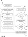
- control logic 200 that may be executed by the computing system 112 (or any other suitable computing system) for adjusting swath lines for a work vehicle is illustrated in accordance with aspects of the present subject matter.
- the control logic 200 shown in FIG. 3 is representative of steps of one embodiment of an algorithm that can be executed to adjust swath lines for a work vehicle based on one or more operating parameters of the vehicle and/or an associated implement to ensure the vehicle/implement can travel along the swath lines regardless of vehicle performance.
- control logic 200 may be advantageously utilized in association with a system installed on or forming part of a work vehicle to allow for real-time adjustment of swath lines for a work vehicle without requiring substantial computing resources and/or processing time.
- control logic 200 may be used in association with any other suitable system, application, and/or the like for generating swath lines for a work vehicle.
- the control logic 200 includes accessing a swath line corresponding to a pass to be made across a field by a work vehicle.
- the computing system 112 may be configured to access a swath line corresponding to a pass to be made across a field (e.g., when performing an agricultural operation) by the vehicle/implement 10/12.
- the swath line may be generated during a previous operation (such as by recording the travel path of a vehicle performing the previous operation) and stored in the memory device(s) 118 of the computing system 112. Thereafter, the computing system 112 may retrieve the stored swath line from the memory device(s) 118 before performing the corresponding pass across the field.
- the control logic 200 includes controlling the operation of the work vehicle such that the work vehicle travels along the swath line to make the pass across the field.
- the computing system 112 is configured to control the operation of one or more components of the work vehicle 10 and/or the associated implement 12 such that the vehicle/implement 10/12 makes a pass across the field (e.g., to perform an agricultural operation thereon).
- the computing system 112 may receive location data (e.g., coordinates) from the location sensor 110 via the communicative link 114. The received location data may, in turn, be used to determine the position of the vehicle/implement 10/12 relative to the accessed swath line.
- the computing system 112 may transmit control signals to the steering actuator 108 via the communicative link 114 to control the direction of travel 14 of the vehicle/implement 10/12 such that the vehicle/implement 10/12 travels along the accessed swath line to make the pass.
- the control logic 200 includes receiving sensor data indicative of an operating parameter of the work vehicle.
- the computing system 112 may be communicatively coupled to the operating parameter sensor(s) 111 via the communicative link 114.
- the computing system 112 may receive data from the operating parameter sensor(s) 111. Such data may, in turn, be indicative of one or more operating parameters of the work vehicle 10 and/or implement 12.
- the control logic 200 includes determining the operating parameter of the work vehicle based on the received sensor data as the work vehicle travels along the swath line. Specifically, in several embodiments, as the vehicle/implement 10/12 travels along the accessed swath line to make the pass, the computing system 112 may determine one or more operating parameters of the work vehicle 10 and/or the implement 12 based on the sensor data received at (206).
- any suitable operating parameter(s) of the vehicle 10 and/or the implement 12 may be determined.
- the determined operating parameter(s) may include one or more vehicle dynamics parameters, such as the turning radius of the vehicle 10, the slew rate of the vehicle 10 and the implement 12, the lateral slip of the vehicle 10, the understeer and/or oversteer of the vehicle 10, and/or the like.
- the determined operating parameter(s) may include one or more vehicle loading parameters, such as the total weight of the vehicle 10 and/or the implement 12, the weight on the front axle of the vehicle 10, and/or the like.
- the operating parameter(s) determined at (208) is used to adjust accessed swath line to ensure the vehicle/implement 10/12 can travel along the swath line as the performance of the vehicle/implement 10/12 (e.g., its turning radius/slew rate) varies because of the field conditions.
- the curved portion(s) of accessed swath line may be adjusted based on the determined operating parameter(s).
- the control logic 200 includes determining the minimum turning radius of the work vehicle based on the determined operating parameter. More specifically, field conditions may impact the performance of the vehicle 10 and/or the implement 12. For example, when the field is muddy, the minimum turning radius of the vehicle 10 and the minimum slew rate of the vehicle 10 and implement 12 may be less than when the field is dry. Thus, the minimum turning and slew radii may differ as field conditions vary. Moreover, vehicle loading may affect the minimum turning and slew radii. As such, in several embodiments, the computing system 112 may determine the minimum turning radius of the vehicle 10 and/or the minimum slew rate of the vehicle 10 and implement 12 based the determined operating parameter(s). For example, in one embodiment, the computing system 112 may use the determined turning radius of the vehicle 10 and the steering angle of the vehicle 10 to determine the minimum turning radius of the vehicle 10 under the current field conditions and/or vehicle loading.
- the control logic 200 includes identifying a curved portion of the accessed swath line positioned forward of the work vehicle relative to the direction of travel.
- the computing system 112 may analyze the portion of the accessed swath line positioned forward of the vehicle/implement 10/12 relative to the direction of travel 14 to identify any curved portions thereof.
- the computing system 112 may use any suitable algorithm(s) or technique(s) to identify the curved portion(s) of the accessed swath line.
- the computing system 112 may determine the rate of change of the curvature of the curved portion.
- the control logic 200 includes determining the radius of a given identified curved portion.
- the computing system 112 may determine the radius of a given curved portion of the swath line identified at (212).
- the computing system 112 may use any suitable algorithm(s) or technique(s) to determine the radius of the given curved portion.
- the control logic 200 includes comparing the determined minimum turning radius of the work vehicle to the determined radius of the given identified curved portion.
- the computing system 112 may compare the minimum turning radius of the work vehicle 10 and/or the slew angle of the vehicle 10 and the implement 12 determined at (210) to the radius of the given identified curved portion determined at (214). When the minimum turning radius of the work vehicle 10 the vehicle 10 and the implement 12 is less the radius of the given curved portion, no adjustment of the given curved portion of the swath line is needed. In such instances, the control logic 200 proceeds to (220).
- control logic 200 proceeds to (218).
- the computing system 112 may compare the determined rate of change of the curvature of the curved portion determined at (212) to the predetermined maximum rate of change. When the determined rate of change of the curvature is less the predetermined maximum rate of change, no adjustment of the given curved portion of the swath line is needed. In such instances, the control logic 200 proceeds to (220). Conversely, when the determined rate of change of the curvature is greater the predetermined maximum rate of change, the vehicle 10 and/or implement 12 are unable to traverse the given curved portion. In such instances, the control logic 200 proceeds to (218).
- the control logic 200 includes adjusting the given curved portion of the accessed swath line such that the radius of the given curved portion is increased.
- the computing system 112 may adjust the given curved portion of the accessed swath line such that its radius is increased, thereby allowing the vehicle/implement 10/12 to travel long the adjusted portion.
- the radius of the given curved portion may be increased to be equal to or greater than (e.g., five percent greater than) than the minimum turning radius or slew radii (e.g., whichever is larger).
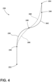
- FIG. 4 illustrates an example swath line 230 for use in guiding the vehicle/implement 10/12 across the field. More specifically, the swath line 230 extends from a point 232 to a point 234. Furthermore, the swath line 130 includes a first curved portion 236 extending from a point 238 to a point 240 and a second curved portion 242 extending from a point 240 to a point 244. As shown, the first and second curved portions 236, 242 have been adjusted (e.g., as indicated by dashed lines 246 and 248, respectively) to increase their radii. Thus, the minimum turning and slew radii needed to traverse the adjusted curved portions 246, 248 is greater, thereby allowing vehicle/implement 10/12 to travel along these portions, such as in muddy conditions or under high vehicle loading.
- the control logic 200 includes determining whether there are any other curved portions of the accessed swath that need to be analyzed. Specifically, in several embodiments, after analyzing and, if necessary, adjusting the given curved portion of the swath line at (214) - (218), the computing system 112 is configured to determine whether there are any other curved portions of the accessed swath that need to be analyzed. When another curved portion of the swath line needs to be analyzed, the control logic 200 returns to (214). Conversely, when there are no other curved portions of the swath line that need to be analyzed, the control logic 200 proceeds to (222).
- the control logic 200 includes controlling the operation of the work vehicle such that the work vehicle travels along the adjusted portion of the swath line.
- the computing system 112 is configured to configured to control the operation of one or more components of the work vehicle 10 and/or the associated implement 12 such that the vehicle/implement 10/12 travels along the adjusted swath line.
- the computing system 112 may use the received location data to determine the position of the vehicle/implement 10/12 relative to the adjusted swath line.
- the computing system 112 may transmit control signals to the steering actuator 108 via the communicative link 114 to control the direction of travel 14 of the vehicle/implement 10/12 such that the vehicle/implement 10/12 travels along the adjusted swath line to make the pass. Thereafter, the control logic 200 may return to (206).
- Adjusting a swath line used to guide the work vehicle/implement 10/12 across a field based on an operating parameter(s) determined as the vehicle/implement 10/12 travels across the field improves the operation of the vehicle 10 and/or the implement 12. More specifically, as described above, field conditions and/or vehicle loading may affect the performance the vehicle 10 and/or the implement 12. As such, in certain instances, the vehicle/implement 10/12 may be unable to follow the swath line being used to guide the vehicle.
- control logic 200 ensures that the vehicle/implement 10/12 can traverse the swath line as field conditions and/or vehicle loading vary.
- the same field conditions may affect different vehicles differently.
- the turning radius of one work vehicle may be more impacted by the same muddy conditions than another work vehicle.
- differing vehicle loading may cause the same field conditions to affect a vehicle differently.
- the control logic 200 ensure different work vehicles and vehicles of varying loads can traverse the swath line.
- FIG. 5 a flow diagram of one embodiment of a method 300 for adjusting swath lines for a work vehicle is illustrated in accordance with aspects of the present subject matter.
- the method 300 will be described herein with reference to the work vehicle 10, the agricultural implement 12, and the system 100 described above with reference to FIGS. 1-4 .
- the disclosed method 300 may generally be implemented with any work vehicle having any suitable vehicle configuration, with any agricultural implement having any suitable implement configuration, and/or any within system having any suitable system configuration.
- FIG. 5 depicts steps performed in a particular order for purposes of illustration and discussion, the methods discussed herein are not limited to any particular order or arrangement. The various steps of the methods disclosed herein can be omitted, rearranged, combined, and/or adapted in various ways without deviating from the scope of the present disclosure.
- the method 300 includes accessing, with a computing system, a swath line corresponding to a pass to be made across a field by the work vehicle.
- a computing system For example, as described above, the computing system 112 may be configured to access a swath line (e.g., stored within its memory device(s) 118) corresponding to a pass to be made across a field by the work vehicle/implement 10/12.
- the method 300 includes controlling, with the computing system, the operation of the work vehicle such that the work vehicle travels along the swath line to make the pass across the field.
- the computing system 112 may be configured to control the operation of one or more components of the work vehicle/implement 10/12 (e.g., the steering actuator 108) such that the work vehicle/implement 10/12 travels along the swath line to make the pass across the field.
- the method 300 includes receiving, with the computing system, sensor data indicative of an operating parameter of the work vehicle.
- the computing system 112 may be configured to receive data from the operating parameter sensor(s) 111 that is indicative of an operating parameter(s) of the work vehicle 10 and/or the implement 12.
- the method 300 includes determining, with the computing system, the operating parameter of the work vehicle based on the received sensor data as the work vehicle travels along the swath line.
- the computing system 112 may be configured to determine the operating parameter(s) of the work vehicle 10 and/or the implement 12 based on the received sensor data as the vehicle/implement 10/12 travels along the swath line.
- the method 300 includes adjusting, with the computing system, a portion of the swath line positioned forward of the work vehicle relative to a direction of travel of the work vehicle based on the determined operating parameter as the work vehicle travels along the swath line.
- the computing system 112 may be configured to adjust at least a portion of the swath line positioned forward of the vehicle/implement 10/12 relative to the direction of travel 14 based on the determined operating parameter as the vehicle/implement 10/12 travels along the swath line.
- the steps of the control logic 200 and the method 300 are performed by the computing system 112 upon loading and executing software code or instructions which are tangibly stored on a tangible computer readable medium, such as on a magnetic medium, e.g., a computer hard drive, an optical medium, e.g., an optical disc, solid-state memory, e.g., flash memory, or other storage media known in the art.
- a tangible computer readable medium such as on a magnetic medium, e.g., a computer hard drive, an optical medium, e.g., an optical disc, solid-state memory, e.g., flash memory, or other storage media known in the art.
- any of the functionality performed by the computing system 112 described herein, such as the control logic 200 and the method 300 is implemented in software code or instructions which are tangibly stored on a tangible computer readable medium.
- the computing system 112 loads the software code or instructions via a direct interface with the computer readable medium or via a wired and/or wireless network. Upon loading
Landscapes
- Engineering & Computer Science (AREA)
- Mechanical Engineering (AREA)
- Life Sciences & Earth Sciences (AREA)
- Chemical & Material Sciences (AREA)
- Combustion & Propulsion (AREA)
- Transportation (AREA)
- Soil Sciences (AREA)
- Environmental Sciences (AREA)
- Automation & Control Theory (AREA)
- Physics & Mathematics (AREA)
- General Physics & Mathematics (AREA)
- Remote Sensing (AREA)
- Radar, Positioning & Navigation (AREA)
- Aviation & Aerospace Engineering (AREA)
- Control Of Position, Course, Altitude, Or Attitude Of Moving Bodies (AREA)
- Guiding Agricultural Machines (AREA)
Applications Claiming Priority (1)
| Application Number | Priority Date | Filing Date | Title |
|---|---|---|---|
| US17/560,959 US12185651B2 (en) | 2021-12-23 | 2021-12-23 | System and method for adjusting swath lines for a work vehicle |
Publications (1)
| Publication Number | Publication Date |
|---|---|
| EP4201176A1 true EP4201176A1 (fr) | 2023-06-28 |
Family
ID=84520069
Family Applications (1)
| Application Number | Title | Priority Date | Filing Date |
|---|---|---|---|
| EP22213075.9A Withdrawn EP4201176A1 (fr) | 2021-12-23 | 2022-12-13 | Système et procédé de réglage de lignes de balayage pour un véhicule de travail |
Country Status (4)
| Country | Link |
|---|---|
| US (1) | US12185651B2 (fr) |
| EP (1) | EP4201176A1 (fr) |
| CN (1) | CN116373864A (fr) |
| BR (1) | BR102022026176A2 (fr) |
Citations (2)
| Publication number | Priority date | Publication date | Assignee | Title |
|---|---|---|---|---|
| US20090265053A1 (en) * | 2007-03-02 | 2009-10-22 | Dix Peter J | Method for creating spiral swath patterns for convex polygon shaped field boundaries |
| US20210267115A1 (en) * | 2020-03-02 | 2021-09-02 | Stephen Filip Fjelstad | Guidance systems and methods |
Family Cites Families (30)
| Publication number | Priority date | Publication date | Assignee | Title |
|---|---|---|---|---|
| US6377872B1 (en) * | 1999-07-02 | 2002-04-23 | Bae Systems Information And Electronic Systems Integration Inc | Apparatus and method for microwave imaging and excavation of objects |
| US7162348B2 (en) | 2002-12-11 | 2007-01-09 | Hemisphere Gps Llc | Articulated equipment position control system and method |
| US7216033B2 (en) | 2003-03-31 | 2007-05-08 | Deere & Company | Path planner and method for planning a contour path of a vehicle |
| US6804597B1 (en) | 2003-07-14 | 2004-10-12 | New Holland North America, Inc. | Automatic guidance system for towed farm implements |
| US7860628B2 (en) * | 2005-06-09 | 2010-12-28 | Trimble Navigation Limited | System for guiding a farm implement between swaths |
| US7844378B2 (en) | 2006-10-05 | 2010-11-30 | Trimble Navigation Limited | Farm apparatus having implement sidehill drift compensation |
| US7715979B2 (en) * | 2006-10-27 | 2010-05-11 | Cnh America Llc | Nudge compensation for curved swath paths |
| US7747370B2 (en) * | 2007-04-03 | 2010-06-29 | Cnh America Llc | Method for creating end of row turns for agricultural vehicles |
| US8209075B2 (en) | 2007-07-31 | 2012-06-26 | Deere & Company | Method and system for generating end turns |
| US8112201B2 (en) | 2008-10-02 | 2012-02-07 | Trimble Navigation Limited | Automatic control of passive, towed implements |
| US8494726B2 (en) | 2011-05-16 | 2013-07-23 | Trimble Navigation Ltd. | Agricultural autopilot path adjustment |
| US8983767B2 (en) * | 2012-03-02 | 2015-03-17 | Jaybridge Robotics, Inc. | Computer-implemented method and system for generating swath coverage patterns for polygonal and pseudo-polygonal shaped fields |
| GB201223363D0 (en) * | 2012-12-24 | 2013-02-06 | Agco Int Gmbh | Path planning method for agricultural vehicle guidance |
| US9826674B2 (en) * | 2014-07-25 | 2017-11-28 | Agco Corporation | Vehicle guidance system |
| US9374939B2 (en) | 2014-08-29 | 2016-06-28 | Deere & Company | System and method for steering of an implement on sloped ground |
| US9795074B2 (en) * | 2015-10-27 | 2017-10-24 | Cnh Industrial America Llc | Automatic swath generation device and methods |
| US9974225B2 (en) * | 2016-01-14 | 2018-05-22 | Cnh Industrial America Llc | System and method for generating and implementing an end-of-row turn path |
| US10368475B2 (en) * | 2016-04-19 | 2019-08-06 | CropZilla Software, Inc. | Machine guidance for optimal working direction of travel |
| US10143126B2 (en) | 2016-06-10 | 2018-12-04 | Cnh Industrial America Llc | Planning and control of autonomous agricultural operations |
| US10251329B2 (en) | 2016-06-10 | 2019-04-09 | Cnh Industrial Canada, Ltd. | Planning and control of autonomous agricultural operations |
| US10795351B2 (en) | 2016-07-19 | 2020-10-06 | Raven Industries, Inc. | System and method for autonomous control of agricultural machinery and equipment |
| US11726485B2 (en) * | 2016-09-05 | 2023-08-15 | Kubota Corporation | Autonomous work vehicle travel system, travel route managing device, travel route generating device, and travel route determining device |
| WO2019089853A1 (fr) | 2017-10-31 | 2019-05-09 | Agjunction Llc | Cartographie de terrain en trois dimensions |
| US11641790B2 (en) | 2018-05-09 | 2023-05-09 | Deere & Company | Method of planning a path for a vehicle having a work tool and a vehicle path planning system |
| US10973171B2 (en) * | 2018-10-17 | 2021-04-13 | Cnh Industrial America Llc | System and method for monitoring field profiles based on data from multiple types of sensors |
| US11224154B2 (en) * | 2019-03-19 | 2022-01-18 | Cnh Industrial America Llc | Headland turn planning for a work vehicle |
| US11864484B2 (en) * | 2019-11-06 | 2024-01-09 | Cnh Industrial Canada, Ltd. | System and method for determining soil clod size or residue coverage of a field during a non-soil-working operation |
| US12022758B2 (en) * | 2020-10-26 | 2024-07-02 | Cnh Industrial America Llc | Swath acquisition system for an agricultural vehicle and an agricultural implement |
| US12604807B2 (en) * | 2021-01-05 | 2026-04-21 | CNH Industrial America PLLC | Agricultural system for controllably optimizing harvesting of forage |
| US12004439B2 (en) * | 2021-01-18 | 2024-06-11 | Cnh Industrial America Llc | Bale retriever that generates driveable path for efficiency and to reduce compaction |
-
2021
- 2021-12-23 US US17/560,959 patent/US12185651B2/en active Active
-
2022
- 2022-12-13 EP EP22213075.9A patent/EP4201176A1/fr not_active Withdrawn
- 2022-12-21 BR BR102022026176-8A patent/BR102022026176A2/pt unknown
- 2022-12-23 CN CN202211662227.3A patent/CN116373864A/zh active Pending
Patent Citations (2)
| Publication number | Priority date | Publication date | Assignee | Title |
|---|---|---|---|---|
| US20090265053A1 (en) * | 2007-03-02 | 2009-10-22 | Dix Peter J | Method for creating spiral swath patterns for convex polygon shaped field boundaries |
| US20210267115A1 (en) * | 2020-03-02 | 2021-09-02 | Stephen Filip Fjelstad | Guidance systems and methods |
Also Published As
| Publication number | Publication date |
|---|---|
| US12185651B2 (en) | 2025-01-07 |
| US20230200279A1 (en) | 2023-06-29 |
| BR102022026176A2 (pt) | 2023-12-05 |
| CN116373864A (zh) | 2023-07-04 |
Similar Documents
| Publication | Publication Date | Title |
|---|---|---|
| US11445656B2 (en) | System and method for preventing material accumulation relative to ground engaging tools of an agricultural implement | |
| US20210132028A1 (en) | Systems and methods for monitoring field conditions | |
| EP3815487A1 (fr) | Systèmes et procédés d'évaluation de la performance d'un outil agricole | |
| US11530528B2 (en) | System and method for detecting tripping of ground engaging tools based on implement frame motion | |
| US20210176912A1 (en) | System and method for assessing agricultural operation performance based on image data of processed and unprocessed portions of the field | |
| EP4201175A1 (fr) | Système et procédé de réglage de lignes de balayage pour un véhicule de travail | |
| EP4201176A1 (fr) | Système et procédé de réglage de lignes de balayage pour un véhicule de travail | |
| EP4201178A1 (fr) | Système et procédé de génération de lignes de bande pour un véhicule de travail | |
| US20250212712A1 (en) | System and Method for Detecting Simultaneous Disk Plugging on a Tillage Implement | |
| US20230189687A1 (en) | System and method for generating swath lines for a work vehicle | |
| US20250380622A1 (en) | System and method for controlling the operation of an agricultural implement | |
| US12089519B2 (en) | System and method for controlling the operation of an agricultural implement | |
| US12102025B2 (en) | System and method for controlling the operation of an agricultural implement | |
| US12457916B2 (en) | Systems and methods for monitoring disc conditions of agricultural implements using soil density measurements | |
| US20230380318A1 (en) | Systems and methods for monitoring disc conditions of agricultural implements based on monitored sub-surface density profiles | |
| US20250208004A1 (en) | System and Method for Detecting Disk Plugging on a Tillage Implement | |
| US20230196851A1 (en) | Agricultural system and method for monitoring wear rates of agricultural implements | |
| US12201043B2 (en) | System and method for detecting bent disk blades on an agricultural implement | |
| US20250346232A1 (en) | System and method for controlling the operation of an agricultural implement | |
| US20250113754A1 (en) | System and method for controlling the operation of an agricultural implement | |
| US12593741B2 (en) | Agricultural system and method for monitoring field characteristics of a field | |
| US20250008860A1 (en) | System and method for detecting damaged disk blades on an agricultural implement | |
| US12568871B2 (en) | System and method for determining residue coverage of a field | |
| US20240341213A1 (en) | System and method for detecting disk blade bearing failure on an agricultural implement | |
| US20250057069A1 (en) | System and method for controlling the operation of ground-engaging tools of an agricultural implement |
Legal Events
| Date | Code | Title | Description |
|---|---|---|---|
| PUAI | Public reference made under article 153(3) epc to a published international application that has entered the european phase |
Free format text: ORIGINAL CODE: 0009012 |
|
| STAA | Information on the status of an ep patent application or granted ep patent |
Free format text: STATUS: THE APPLICATION HAS BEEN PUBLISHED |
|
| AK | Designated contracting states |
Kind code of ref document: A1 Designated state(s): AL AT BE BG CH CY CZ DE DK EE ES FI FR GB GR HR HU IE IS IT LI LT LU LV MC ME MK MT NL NO PL PT RO RS SE SI SK SM TR |
|
| STAA | Information on the status of an ep patent application or granted ep patent |
Free format text: STATUS: REQUEST FOR EXAMINATION WAS MADE |
|
| 17P | Request for examination filed |
Effective date: 20240102 |
|
| RBV | Designated contracting states (corrected) |
Designated state(s): AL AT BE BG CH CY CZ DE DK EE ES FI FR GB GR HR HU IE IS IT LI LT LU LV MC ME MK MT NL NO PL PT RO RS SE SI SK SM TR |
|
| STAA | Information on the status of an ep patent application or granted ep patent |
Free format text: STATUS: THE APPLICATION IS DEEMED TO BE WITHDRAWN |
|
| 18D | Application deemed to be withdrawn |
Effective date: 20240103 |