EP4201192B1 - Dispositif d'arrimage du chargement pour wagons agricoles - Google Patents
Dispositif d'arrimage du chargement pour wagons agricoles Download PDFInfo
- Publication number
- EP4201192B1 EP4201192B1 EP22000044.2A EP22000044A EP4201192B1 EP 4201192 B1 EP4201192 B1 EP 4201192B1 EP 22000044 A EP22000044 A EP 22000044A EP 4201192 B1 EP4201192 B1 EP 4201192B1
- Authority
- EP
- European Patent Office
- Prior art keywords
- securing
- wall body
- wall
- arm
- articulation point
- Prior art date
- Legal status (The legal status is an assumption and is not a legal conclusion. Google has not performed a legal analysis and makes no representation as to the accuracy of the status listed.)
- Active
Links
Images



Classifications
-
- B—PERFORMING OPERATIONS; TRANSPORTING
- B60—VEHICLES IN GENERAL
- B60P—VEHICLES ADAPTED FOR LOAD TRANSPORTATION OR TO TRANSPORT, TO CARRY, OR TO COMPRISE SPECIAL LOADS OR OBJECTS
- B60P7/00—Securing or covering of load on vehicles
- B60P7/06—Securing of load
- B60P7/08—Securing to the vehicle floor or sides
- B60P7/12—Securing to the vehicle floor or sides the load being tree-trunks, beams, drums, tubes, or the like
-
- A—HUMAN NECESSITIES
- A01—AGRICULTURE; FORESTRY; ANIMAL HUSBANDRY; HUNTING; TRAPPING; FISHING
- A01D—HARVESTING; MOWING
- A01D90/00—Vehicles for carrying harvested crops with means for selfloading or unloading
- A01D90/02—Loading means
- A01D90/08—Loading means with bale-forming means additionally used for loading; with means for picking-up bales and transporting them into the vehicle
- A01D90/083—Round-bale trailers
-
- B—PERFORMING OPERATIONS; TRANSPORTING
- B60—VEHICLES IN GENERAL
- B60P—VEHICLES ADAPTED FOR LOAD TRANSPORTATION OR TO TRANSPORT, TO CARRY, OR TO COMPRISE SPECIAL LOADS OR OBJECTS
- B60P7/00—Securing or covering of load on vehicles
- B60P7/06—Securing of load
- B60P7/135—Securing or supporting by load bracing means
Definitions
- the invention relates to a load securing device for agricultural transport wagons, in particular for bale transport wagons for transporting, for example, straw bales or hay bales, which can be in the form of round bales or in the form of square bales, although other piecemeal transport goods can also be considered, such as fruit crates.
- Agricultural transport wagons for transporting pressed straw bales or rolled hay bales or other bulky loads require free access to the loading platform of the transport wagon from at least one side for loading.
- a longitudinal side wall element of the transport wagon securing the load on the relevant side of the loading platform must therefore be movable between a securing position and a position in which it does not obstruct the accessibility of the loading platform from the relevant side.
- a load securing device for such agricultural transport wagons is known in which, instead of a frame-lattice-like and thus overall rigid longitudinal side wall, a flexible longitudinal side wall is provided for securing the load on at least one long side of the transport wagon.
- the flexible longitudinal side wall consists of a beam extending over the long side and serving as a tension rod and a number of flexible belts distributed over the long side, which run between the beam and an anchoring point located below the loading area of the loading platform.
- the beam can be moved between a raised tensioning position, in which the tensioning belts form a flexible side wall that laterally closes off the loading space, and a lowered position below the loading area of the loading platform.
- the rigid longitudinal side wall element is reduced to a narrow beam, in contrast to the frame-lattice-like longitudinal side walls of the other known embodiments, which extend over a considerable height.
- the latter known arrangement thus overcomes both the problem that exists with a downwardly pivoting frame grid longitudinal side wall, that the downwardly pivoted frame grid longitudinal side wall prevents forklifts or similar loading vehicles from approaching the loading platform when loading, and the problem that exists with an upwardly pivoting frame grid longitudinal side wall of a risk of accident if the upwardly pivoted longitudinal side wall threatens to fall down due to a technical defect or incorrect operation.
- the object of the invention is to provide a further optimization of a load securing device for agricultural bale transport wagons, in particular with regard to extended securing options for different loads.
- the arrangement according to the invention uses the DE 20 2015 005 847 U1 known reduction of a rigid longitudinal side wall element to a relatively narrow beam in order to leave enough space down to the ground even when it is lowered below the loading platform level to allow partial driving under by loading vehicles approaching from the side without hindrance.
- the arrangement according to the invention enables securing positions of the beam at different heights corresponding to different loads, for example with one layer or two layers of bales in the form of round bales or square bales, or with boxes.
- a safety bar is provided on both long sides of the transport trolley, but it is also possible to provide a safety bar only on one long side of the transport trolley and to provide the other long side with a rigid, fixed long side wall.
- This improvement of the load securing device with regard to load securing on the long sides of the transport vehicle can also be further optimized with regard to load securing at the front and rear ends of the vehicle by the fact that, according to the invention, the end walls arranged in a fixed position there are each designed as a folding grid in an upper area, which can be folded optionally into a position swung out with respect to the respective loading platform end or into a swung in position aligned with the loading platform end in order to achieve an optimized Loading of the transport vehicle is permitted, as will be explained in more detail in the following example description.
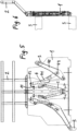
- the Figures 1 to 6 show only one end wall of the transport vehicle, omitting the rest of the transport vehicle, as it is located at both the front and rear is arranged at the end of the car, namely in the Figures 1 , 3 and 5 each in the view from the outside, and in the Figures 2 , 4 and 6 each in side view.
- Each end wall has a wall body 1 fixedly arranged at the front or rear end of the transport trolley. This can extend (not shown) over the entire height of the transport trolley, or in a preferred embodiment of the invention, as shown, only extend over a part of the height of the transport trolley, in which case a foldable grid 2 is connected to the upper end of the wall body 1, which can be moved between a folded-in position ( Figure 7 ) for transporting square bales and an unfolded position ( Figure 8 ) can be folded for transporting round bales.
- the wall body 1 forms the supporting structure for the actuating mechanism for securing beams 3, which in the illustrated embodiment run along each long side of the transport vehicle in order to secure the load on the respective long side.
- this actuating mechanism is preferably arranged within the wall body 1, which thus protects the actuating mechanism both from contamination and from damage caused by external mechanical influences and at the same time protects against the risk of accidents, in that the wall body 1, as a housing for the actuating mechanism, prevents persons using the trolley from getting their body parts into the moving actuating mechanism in any way.
- the transport trolley can be designed with a securing bar 3 on both long sides and consequently with a double actuating mechanism in each end wall in order to be able to load the transport trolley from one or the other or from both sides at the same time when the securing bar 3 is lowered under the loading platform.
- a securing bar 3 can only be provided on one long side of the transport trolley, in which case only a single actuating mechanism is present, while a fixed, for example grid-like, long side wall is arranged on the other long side.
- a safety bar 3 is provided on both sides of the vehicle.
- Figures 1 and 2 Both safety bars 3 on the two long sides of the trolley are in their lowered position for free access to the Loading platform shown.
- one safety bar (on the right side of the trolley in the front wall view) is in the lowered position, while the safety bar 3 on the other side of the trolley is in the fully raised position.
- one of the securing beams 3 (on the left side in the front wall view) is shown in the lowered position and the securing beam 3 on the other trolley side is in the half-raised position.
- An actuating device for the safety beams 3 consists of an actuating mechanism in the form of a rod arranged on the wall body 1 of both the front end wall and the rear end wall of the transport carriage, which is provided twice in a mirror-image design for each of the safety beams 3 arranged on both sides of the transport carriage.
- Each rod consists of a swivel arm 4, which in turn consists of a "lower arm” 41 and an “upper arm” 42, which are connected to one another in an articulated manner by an elbow joint 43.
- the upper arm 41 is connected at one end to the wall body 1 via an articulation point 11, and at its other end to the joint 43 between the upper arm 41 and the lower arm 42 of the swivel arm 4.
- the lower arm 42 is connected at its free end to the securing beam 3 in an articulated manner.
- a first hydraulic cylinder 5 is connected at one end to the wall body 1 via a pivot point 12, and at its other end is articulated at a distance from the joint 43 to the end of the lower arm 42 remote from the securing beam 3.
- the articulation point 12 of the first hydraulic cylinder 5 on the wall body 1 is located below the connection of this first hydraulic cylinder 5 to the upper arm 41, which in turn is located below the articulation point 11 of the upper arm 41 on the wall body 1.
- the articulation point 13 of the second hydraulic cylinder 6 is located in the area of the articulation point 11 of the upper arm 41 on the wall body 1, but is arranged slightly offset from it. In the embodiment shown, the articulation point 13 is located slightly above and slightly laterally offset from the articulation point 11.
- the safety beam 3 When the safety beam 3 is raised both to the fully raised position and to the half-raised position, the safety beam 3 describes an arcuate path due to the pivoting movement of the pivot arm 4 or the lower arm 42, whereby the arc initially leads laterally outwards from the lower position of the safety beam 3 and then laterally inwards again in the upper area.
- the arc of movement of the safety beam 3 can be adjusted so that the safety beam 3 moves laterally inwards over the edge of the loading platform by a certain distance both in the fully raised position and in the half-raised position in order to clamp the load.
- flexible belts 7 are arranged at mutual distances and secure the load underneath the securing beam 3 along the long side of the transport vehicle when the latter is in a raised securing position by forming a flexible long side wall together.
- the belts 7 are preferably fastened with their lower ends underneath the loading area. When the securing beam 3 is lowered into the lowered position, the belts form flexible loops which do not hinder the driving under the loading area with a loading vehicle.
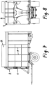
- FIGS. 7 and 8 show the front part of the transport wagon in side view and front view, fully loaded with square bales Q.
- the securing beam 3 is in the fully raised position and the gate 2 is in the folded-in position, i.e. aligned with the wall body 1.
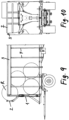
- FIGS 9 and 10 show the front part of the transport wagon in side view and in front view, fully loaded with round bales R.
- the securing bar 3 is in the fully raised position and the gate 2 is folded out, which means that an additional round bale R can be loaded at the front and rear ends of the transport wagon, which would not be possible without the foldable gate.
- FIGS. 11 and 12 show the front part of the trolley in side view and in front view loaded with boxes K, and the securing beam 3 is raised to half height.
Landscapes
- Engineering & Computer Science (AREA)
- Transportation (AREA)
- Mechanical Engineering (AREA)
- Life Sciences & Earth Sciences (AREA)
- Environmental Sciences (AREA)
- Handcart (AREA)
- Loading Or Unloading Of Vehicles (AREA)
- Auxiliary Methods And Devices For Loading And Unloading (AREA)
Claims (6)
- Dispositif d'arrimage de charge pour chariot de transport agricole, qui présente une plateforme de chargement, une paroi frontale avant et une paroi frontale arrière ainsi que des agencements de panneaux latéraux sur les panneaux latéraux longitudinaux, sachant qu'au moins un agencement de panneaux latéraux est composé d'une traverse de sécurité rigide (3) s'étendant sur le côté longitudinal du chariot de transport et d'éléments de panneau flexibles se déployant entre celle-ci et la plateforme de chargement, comme par exemple des sangles (7), sachant que la traverse de sécurité (3) est mobile entre une position de chargement, dans laquelle la traverse de sécurité (3) est abaissée dans une position au-dessous du bord de plateforme de chargement, et une position de sécurité relevée au moyen d'un mécanisme d'actionnement qui présente des mécanismes d'actionnement (4, 5, 6) disposés sur les deux parois frontales du chariot de transport et reliés respectivement à une extrémité de la traverse de sécurité (3),caractérisé en ce que chaque mécanisme d'actionnement comprend un bras pivotant (4), qui est composé d'un bras supérieur (41), qui est articulé environ à mi-hauteur par rapport à la hauteur de chargement totale sur un corps de paroi (1) de la paroi frontale respective, et d'un bras inférieur (42) relié à celui-ci par une articulation à charnière (43) dont l'extrémité libre est reliée à la traverse de sécurité (3) de manière articulée,en ce que par ailleurs un premier vérin hydraulique (5) est relié de manière articulée au bras supérieur (41) par une extrémité supérieure sur une zone située entre la zone d'articulation (11) du bras supérieur (41) sur le corps de paroi (1) et l'articulation à charnière (43) et est relié au corps de paroi (1) par une extrémité inférieure sur une zone d'articulation (12) située plus bas et en ce qu'un second vérin hydraulique (6) est relié de manière articulée au bras inférieur (42) par une extrémité inférieure sur une zone décalée par rapport à l'articulation à charnière (43) dans la direction inverse à la traverse de sécurité (3) et est relié au corps de paroi (1) par une extrémité supérieure sur une zone d'articulation (13).
- Dispositif d'arrimage de charge selon la revendication 1, sachant que le premier vérin hydraulique (5) et le second vérin hydraulique (6) sont actionnés au choix, afin de faire pivoter la traverse de sécurité (3) entre la position abaissée et une position complètement relevée ou une position relevée environ à la mi-hauteur.
- Dispositif d'arrimage de charge selon la revendication 1 ou la 2, sachant que la trajectoire de pivotement de la traverse de sécurité (3) en arc générée à l'actionnement du mécanisme d'actionnement respectif, peut s'étendre vers l'intérieur à partir de la position abaissée dans la position complètement relevée ou dans une position relevée environ à la mi-hauteursur une certaine distance latérale au-dessus du bord de la plateforme de chargement.
- Dispositif d'arrimage de charge selon une quelconque des revendications 1 à 3, sachant que la géométrie de chaque mécanisme d'actionnement est agencée de sorte que le bras supérieur (41) et le bras inférieur (42) se trouvent en position pratiquement déployée avec la traverse de sécurité (3) abaissée et que le bras pivotant (4) s'étend obliquement vers le bas et latéralement à partir de la zone d'articulation (11) du bras supérieur (41) sur le corps de paroi (1).
- Dispositif d'arrimage de charge selon une quelconque des revendications 1 à 4, sachant que la zone d'articulation (13) du second vérin hydraulique (6) sur le corps de paroi (1) est agencée sur le corps de paroi (1) de manière décalée d'une petite distance vers le haut et latéralement vers l'extérieur à partir de la zone d'articulation (11) du bras supérieur (41).
- Dispositif d'arrimage de charge selon une quelconque des revendications 1 à 5, sachant que la paroi frontale avant et celle arrière du chariot de transport sont formées respectivement par le corps de paroi (1) s'étendant uniquement sur une partie de la hauteur de paroi frontale et par un élément de paroi se raccordant en haut au corps de paroi (1), qui peut être constitué sous forme de grille (2) et est mobile entre une position repliée à fleur avec le corps de paroi (1) et une position déployée vers l'avant ou vers l'arrière.
Applications Claiming Priority (1)
| Application Number | Priority Date | Filing Date | Title |
|---|---|---|---|
| DE202021003877.9U DE202021003877U1 (de) | 2021-12-27 | 2021-12-27 | Ladungssicherungsvorrichtung für landwirtschaftliche Transportwagen |
Publications (3)
| Publication Number | Publication Date |
|---|---|
| EP4201192A1 EP4201192A1 (fr) | 2023-06-28 |
| EP4201192B1 true EP4201192B1 (fr) | 2024-04-24 |
| EP4201192C0 EP4201192C0 (fr) | 2024-04-24 |
Family
ID=80474086
Family Applications (1)
| Application Number | Title | Priority Date | Filing Date |
|---|---|---|---|
| EP22000044.2A Active EP4201192B1 (fr) | 2021-12-27 | 2022-03-01 | Dispositif d'arrimage du chargement pour wagons agricoles |
Country Status (2)
| Country | Link |
|---|---|
| EP (1) | EP4201192B1 (fr) |
| DE (1) | DE202021003877U1 (fr) |
Families Citing this family (1)
| Publication number | Priority date | Publication date | Assignee | Title |
|---|---|---|---|---|
| CN115924310B (zh) * | 2023-02-20 | 2024-08-16 | 浙江杭绍甬高速公路有限公司 | 预制构件夹装装置及预制构件运输系统 |
Family Cites Families (4)
| Publication number | Priority date | Publication date | Assignee | Title |
|---|---|---|---|---|
| DE102007020735A1 (de) | 2007-05-03 | 2008-11-06 | Georg Krassort | Transportwagen für insbesondere landwirtschaftliches Stückgut |
| DE202013005936U1 (de) * | 2013-07-02 | 2013-08-07 | Torsten Hundertmark | Ladungssicherungssytem für Ballenwagen |
| DE202013008198U1 (de) | 2013-09-11 | 2013-12-09 | Raik Hesse | Transportsicherung mit mechanischer Öffnungsmöglichkeit |
| DE202015005847U1 (de) | 2015-06-08 | 2015-09-23 | Johann Demmler Kg | Ladungssicherungsvorrichtung für landwirtschaftliche Transportwagen |
-
2021
- 2021-12-27 DE DE202021003877.9U patent/DE202021003877U1/de active Active
-
2022
- 2022-03-01 EP EP22000044.2A patent/EP4201192B1/fr active Active
Also Published As
| Publication number | Publication date |
|---|---|
| EP4201192A1 (fr) | 2023-06-28 |
| DE202021003877U1 (de) | 2022-02-10 |
| EP4201192C0 (fr) | 2024-04-24 |
Similar Documents
| Publication | Publication Date | Title |
|---|---|---|
| DE60215537T2 (de) | Unterfahrschutzvorrichtung | |
| EP2186713B1 (fr) | Dispositif de ballastage et véhicule agricole équipé avec ce dernier | |
| EP0808747A1 (fr) | Système de hayon élévateur | |
| DE4335456C2 (de) | Lastkraftwagen für den Transport von Gütern | |
| DE1580672B2 (de) | Hebevorrichtung für Lastwagen mit einer Ladeplattform | |
| DE1580662B2 (de) | Unterhalb einer ladeflaeche, insbesondere eines fahrzeuges, verstaubare ladebuehne | |
| DE2228764A1 (de) | Klappwand fur Mulden Hinterkipper Fahrzeug | |
| EP2042410B1 (fr) | Véhicule agricole | |
| EP3028557B1 (fr) | Faucheuse et procédé de fonctionnement d'une faucheuse | |
| EP4201192B1 (fr) | Dispositif d'arrimage du chargement pour wagons agricoles | |
| WO2011009537A1 (fr) | Véhicule présentant une structure de bras de mât pouvant pivoter vers l'extérieur | |
| EP3159452B1 (fr) | Chargeur frontal | |
| EP1541412A1 (fr) | Système de hayon élévateur | |
| EP3788864B1 (fr) | Dispositif de montage pour machine de travail agricole, machine de travail agricole et attelage pourvue d'une telle machine de travail agricole | |
| EP3549417A1 (fr) | Ensemble de bras de levage pour un relevage hydraulic trois points d'un tracteur ou d'un autre engin de travail agricole ainsi que relevage hydraulic trois points | |
| DE2705979A1 (de) | Vorrichtung an einem langen schleppoder anhaengerwagen | |
| DE3822542A1 (de) | Ladeanhaenger | |
| EP3266292B1 (fr) | Outil agricole tracté et agricole et attelage comprenant un tel outil tracté | |
| EP3326861B1 (fr) | Dispositif d'arrimage de chargement | |
| WO2016162115A1 (fr) | Véhicule de transport de charges lourdes à largeur variable | |
| DE29615981U1 (de) | Fahrzeugtransporter | |
| EP0631975B1 (fr) | Accessoire en particulier pour chariot élévateur | |
| EP1847447B1 (fr) | Ranche pour l'ouverture de chargement d'une construction automobile | |
| DE19822809A1 (de) | Knickrahmengelenktes Ladefahrzeug | |
| DE2832393C2 (de) | Transportfahrzeug, insbesondere Tieflade- Straßenfahrzeug mit veränderbarer Bodenfreiheit |
Legal Events
| Date | Code | Title | Description |
|---|---|---|---|
| PUAI | Public reference made under article 153(3) epc to a published international application that has entered the european phase |
Free format text: ORIGINAL CODE: 0009012 |
|
| STAA | Information on the status of an ep patent application or granted ep patent |
Free format text: STATUS: THE APPLICATION HAS BEEN PUBLISHED |
|
| AK | Designated contracting states |
Kind code of ref document: A1 Designated state(s): AL AT BE BG CH CY CZ DE DK EE ES FI FR GB GR HR HU IE IS IT LI LT LU LV MC MK MT NL NO PL PT RO RS SE SI SK SM TR |
|
| STAA | Information on the status of an ep patent application or granted ep patent |
Free format text: STATUS: REQUEST FOR EXAMINATION WAS MADE |
|
| 17P | Request for examination filed |
Effective date: 20230720 |
|
| RBV | Designated contracting states (corrected) |
Designated state(s): AL AT BE BG CH CY CZ DE DK EE ES FI FR GB GR HR HU IE IS IT LI LT LU LV MC MK MT NL NO PL PT RO RS SE SI SK SM TR |
|
| RAP1 | Party data changed (applicant data changed or rights of an application transferred) |
Owner name: DEMMLER GMBH & CO. KG - FAHRZEUG- UND KAROSSERIEBAU |
|
| GRAP | Despatch of communication of intention to grant a patent |
Free format text: ORIGINAL CODE: EPIDOSNIGR1 |
|
| STAA | Information on the status of an ep patent application or granted ep patent |
Free format text: STATUS: GRANT OF PATENT IS INTENDED |
|
| INTG | Intention to grant announced |
Effective date: 20231218 |
|
| GRAS | Grant fee paid |
Free format text: ORIGINAL CODE: EPIDOSNIGR3 |
|
| GRAA | (expected) grant |
Free format text: ORIGINAL CODE: 0009210 |
|
| STAA | Information on the status of an ep patent application or granted ep patent |
Free format text: STATUS: THE PATENT HAS BEEN GRANTED |
|
| AK | Designated contracting states |
Kind code of ref document: B1 Designated state(s): AL AT BE BG CH CY CZ DE DK EE ES FI FR GB GR HR HU IE IS IT LI LT LU LV MC MK MT NL NO PL PT RO RS SE SI SK SM TR |
|
| REG | Reference to a national code |
Ref country code: GB Ref legal event code: FG4D Free format text: NOT ENGLISH |
|
| REG | Reference to a national code |
Ref country code: CH Ref legal event code: EP |
|
| REG | Reference to a national code |
Ref country code: DE Ref legal event code: R096 Ref document number: 502022000769 Country of ref document: DE |
|
| REG | Reference to a national code |
Ref country code: IE Ref legal event code: FG4D Free format text: LANGUAGE OF EP DOCUMENT: GERMAN |
|
| U01 | Request for unitary effect filed |
Effective date: 20240522 |
|
| U07 | Unitary effect registered |
Designated state(s): AT BE BG DE DK EE FI FR IT LT LU LV MT NL PT SE SI Effective date: 20240603 |
|
| PG25 | Lapsed in a contracting state [announced via postgrant information from national office to epo] |
Ref country code: IS Free format text: LAPSE BECAUSE OF FAILURE TO SUBMIT A TRANSLATION OF THE DESCRIPTION OR TO PAY THE FEE WITHIN THE PRESCRIBED TIME-LIMIT Effective date: 20240824 |
|
| PG25 | Lapsed in a contracting state [announced via postgrant information from national office to epo] |
Ref country code: HR Free format text: LAPSE BECAUSE OF FAILURE TO SUBMIT A TRANSLATION OF THE DESCRIPTION OR TO PAY THE FEE WITHIN THE PRESCRIBED TIME-LIMIT Effective date: 20240424 |
|
| PG25 | Lapsed in a contracting state [announced via postgrant information from national office to epo] |
Ref country code: GR Free format text: LAPSE BECAUSE OF FAILURE TO SUBMIT A TRANSLATION OF THE DESCRIPTION OR TO PAY THE FEE WITHIN THE PRESCRIBED TIME-LIMIT Effective date: 20240725 |
|
| PG25 | Lapsed in a contracting state [announced via postgrant information from national office to epo] |
Ref country code: ES Free format text: LAPSE BECAUSE OF FAILURE TO SUBMIT A TRANSLATION OF THE DESCRIPTION OR TO PAY THE FEE WITHIN THE PRESCRIBED TIME-LIMIT Effective date: 20240424 |
|
| PG25 | Lapsed in a contracting state [announced via postgrant information from national office to epo] |
Ref country code: PL Free format text: LAPSE BECAUSE OF FAILURE TO SUBMIT A TRANSLATION OF THE DESCRIPTION OR TO PAY THE FEE WITHIN THE PRESCRIBED TIME-LIMIT Effective date: 20240424 |
|
| PG25 | Lapsed in a contracting state [announced via postgrant information from national office to epo] |
Ref country code: PL Free format text: LAPSE BECAUSE OF FAILURE TO SUBMIT A TRANSLATION OF THE DESCRIPTION OR TO PAY THE FEE WITHIN THE PRESCRIBED TIME-LIMIT Effective date: 20240424 Ref country code: NO Free format text: LAPSE BECAUSE OF FAILURE TO SUBMIT A TRANSLATION OF THE DESCRIPTION OR TO PAY THE FEE WITHIN THE PRESCRIBED TIME-LIMIT Effective date: 20240724 Ref country code: IS Free format text: LAPSE BECAUSE OF FAILURE TO SUBMIT A TRANSLATION OF THE DESCRIPTION OR TO PAY THE FEE WITHIN THE PRESCRIBED TIME-LIMIT Effective date: 20240824 Ref country code: HR Free format text: LAPSE BECAUSE OF FAILURE TO SUBMIT A TRANSLATION OF THE DESCRIPTION OR TO PAY THE FEE WITHIN THE PRESCRIBED TIME-LIMIT Effective date: 20240424 Ref country code: GR Free format text: LAPSE BECAUSE OF FAILURE TO SUBMIT A TRANSLATION OF THE DESCRIPTION OR TO PAY THE FEE WITHIN THE PRESCRIBED TIME-LIMIT Effective date: 20240725 Ref country code: ES Free format text: LAPSE BECAUSE OF FAILURE TO SUBMIT A TRANSLATION OF THE DESCRIPTION OR TO PAY THE FEE WITHIN THE PRESCRIBED TIME-LIMIT Effective date: 20240424 Ref country code: RS Free format text: LAPSE BECAUSE OF FAILURE TO SUBMIT A TRANSLATION OF THE DESCRIPTION OR TO PAY THE FEE WITHIN THE PRESCRIBED TIME-LIMIT Effective date: 20240724 |
|
| PG25 | Lapsed in a contracting state [announced via postgrant information from national office to epo] |
Ref country code: CZ Free format text: LAPSE BECAUSE OF FAILURE TO SUBMIT A TRANSLATION OF THE DESCRIPTION OR TO PAY THE FEE WITHIN THE PRESCRIBED TIME-LIMIT Effective date: 20240424 |
|
| PG25 | Lapsed in a contracting state [announced via postgrant information from national office to epo] |
Ref country code: SK Free format text: LAPSE BECAUSE OF FAILURE TO SUBMIT A TRANSLATION OF THE DESCRIPTION OR TO PAY THE FEE WITHIN THE PRESCRIBED TIME-LIMIT Effective date: 20240424 Ref country code: RO Free format text: LAPSE BECAUSE OF FAILURE TO SUBMIT A TRANSLATION OF THE DESCRIPTION OR TO PAY THE FEE WITHIN THE PRESCRIBED TIME-LIMIT Effective date: 20240424 |
|
| REG | Reference to a national code |
Ref country code: DE Ref legal event code: R097 Ref document number: 502022000769 Country of ref document: DE |
|
| PG25 | Lapsed in a contracting state [announced via postgrant information from national office to epo] |
Ref country code: SM Free format text: LAPSE BECAUSE OF FAILURE TO SUBMIT A TRANSLATION OF THE DESCRIPTION OR TO PAY THE FEE WITHIN THE PRESCRIBED TIME-LIMIT Effective date: 20240424 |
|
| PG25 | Lapsed in a contracting state [announced via postgrant information from national office to epo] |
Ref country code: SM Free format text: LAPSE BECAUSE OF FAILURE TO SUBMIT A TRANSLATION OF THE DESCRIPTION OR TO PAY THE FEE WITHIN THE PRESCRIBED TIME-LIMIT Effective date: 20240424 Ref country code: SK Free format text: LAPSE BECAUSE OF FAILURE TO SUBMIT A TRANSLATION OF THE DESCRIPTION OR TO PAY THE FEE WITHIN THE PRESCRIBED TIME-LIMIT Effective date: 20240424 Ref country code: RO Free format text: LAPSE BECAUSE OF FAILURE TO SUBMIT A TRANSLATION OF THE DESCRIPTION OR TO PAY THE FEE WITHIN THE PRESCRIBED TIME-LIMIT Effective date: 20240424 Ref country code: CZ Free format text: LAPSE BECAUSE OF FAILURE TO SUBMIT A TRANSLATION OF THE DESCRIPTION OR TO PAY THE FEE WITHIN THE PRESCRIBED TIME-LIMIT Effective date: 20240424 |
|
| PLBE | No opposition filed within time limit |
Free format text: ORIGINAL CODE: 0009261 |
|
| STAA | Information on the status of an ep patent application or granted ep patent |
Free format text: STATUS: NO OPPOSITION FILED WITHIN TIME LIMIT |
|
| 26N | No opposition filed |
Effective date: 20250127 |
|
| U20 | Renewal fee for the european patent with unitary effect paid |
Year of fee payment: 4 Effective date: 20250310 |
|
| PG25 | Lapsed in a contracting state [announced via postgrant information from national office to epo] |
Ref country code: MC Free format text: LAPSE BECAUSE OF FAILURE TO SUBMIT A TRANSLATION OF THE DESCRIPTION OR TO PAY THE FEE WITHIN THE PRESCRIBED TIME-LIMIT Effective date: 20240424 |
|
| REG | Reference to a national code |
Ref country code: CH Ref legal event code: H13 Free format text: ST27 STATUS EVENT CODE: U-0-0-H10-H13 (AS PROVIDED BY THE NATIONAL OFFICE) Effective date: 20251024 |
|
| PG25 | Lapsed in a contracting state [announced via postgrant information from national office to epo] |
Ref country code: CH Free format text: LAPSE BECAUSE OF NON-PAYMENT OF DUE FEES Effective date: 20250331 |
|
| PG25 | Lapsed in a contracting state [announced via postgrant information from national office to epo] |
Ref country code: IE Free format text: LAPSE BECAUSE OF NON-PAYMENT OF DUE FEES Effective date: 20250301 |
|
| U20 | Renewal fee for the european patent with unitary effect paid |
Year of fee payment: 5 Effective date: 20260321 |