EP4201242A1 - Dispositif de fixation magnétique - Google Patents
Dispositif de fixation magnétique Download PDFInfo
- Publication number
- EP4201242A1 EP4201242A1 EP23157694.3A EP23157694A EP4201242A1 EP 4201242 A1 EP4201242 A1 EP 4201242A1 EP 23157694 A EP23157694 A EP 23157694A EP 4201242 A1 EP4201242 A1 EP 4201242A1
- Authority
- EP
- European Patent Office
- Prior art keywords
- abutment surface
- unit
- fastening device
- magnet
- magnetic fastening
- Prior art date
- Legal status (The legal status is an assumption and is not a legal conclusion. Google has not performed a legal analysis and makes no representation as to the accuracy of the status listed.)
- Pending
Links
Images

Classifications
-
- A—HUMAN NECESSITIES
- A42—HEADWEAR
- A42B—HATS; HEAD COVERINGS
- A42B3/00—Helmets; Helmet covers ; Other protective head coverings
- A42B3/04—Parts, details or accessories of helmets
- A42B3/30—Mounting radio sets or communication systems
-
- A—HUMAN NECESSITIES
- A42—HEADWEAR
- A42B—HATS; HEAD COVERINGS
- A42B3/00—Helmets; Helmet covers ; Other protective head coverings
- A42B3/04—Parts, details or accessories of helmets
-
- A—HUMAN NECESSITIES
- A42—HEADWEAR
- A42B—HATS; HEAD COVERINGS
- A42B3/00—Helmets; Helmet covers ; Other protective head coverings
- A42B3/04—Parts, details or accessories of helmets
- A42B3/08—Chin straps or similar retention devices
-
- F—MECHANICAL ENGINEERING; LIGHTING; HEATING; WEAPONS; BLASTING
- F16—ENGINEERING ELEMENTS AND UNITS; GENERAL MEASURES FOR PRODUCING AND MAINTAINING EFFECTIVE FUNCTIONING OF MACHINES OR INSTALLATIONS; THERMAL INSULATION IN GENERAL
- F16B—DEVICES FOR FASTENING OR SECURING CONSTRUCTIONAL ELEMENTS OR MACHINE PARTS TOGETHER, e.g. NAILS, BOLTS, CIRCLIPS, CLAMPS, CLIPS OR WEDGES; JOINTS OR JOINTING
- F16B1/00—Devices for securing together, or preventing relative movement between, constructional elements or machine parts
-
- F—MECHANICAL ENGINEERING; LIGHTING; HEATING; WEAPONS; BLASTING
- F16—ENGINEERING ELEMENTS AND UNITS; GENERAL MEASURES FOR PRODUCING AND MAINTAINING EFFECTIVE FUNCTIONING OF MACHINES OR INSTALLATIONS; THERMAL INSULATION IN GENERAL
- F16B—DEVICES FOR FASTENING OR SECURING CONSTRUCTIONAL ELEMENTS OR MACHINE PARTS TOGETHER, e.g. NAILS, BOLTS, CIRCLIPS, CLAMPS, CLIPS OR WEDGES; JOINTS OR JOINTING
- F16B2200/00—Constructional details of connections not covered for in other groups of this subclass
- F16B2200/83—Use of a magnetic material
Definitions
- the invention relates to a magnetic fastening device for releasably fastening a first unit and a second unit to each other,
- Magnetic fastening devices of the afore-mentioned type are, for example, known from magnetic whiteboards.
- papers or foils may be fastened to a board (constituting the first unit) made from ferromagnetic material, e.g. a ferritic steel sheet, forming the actual whiteboard by using fastening elements (constituting the second unit) comprising permanent magnets.
- the first unit abutment surface and the second unit abutment surface are sandwiching the paper or foil between them when abutting against each other.
- a magnetic fastening device disclosing the features of the preamble part of claim 1 is also known from US-A-2006/133068 . With respect to the prior art, it is further referred to US-A-2015/286117 and US-A-2017/341871 .
- this object is solved by a magnetic fastening device of the afore-mentioned type,
- the magnetic fastening force is supplemented by a form fit between the at least one protrusion and the at least one recess.
- the at least one protrusion and the at least one recess positively mate with each other when said first abutment surface and said second abutment surface abut against each other.
- the magnetic fastening device provides for a synergistic effect between the magnetic fastening and the form fit fastening, as the attractive force between the first and second magnets maintains the form fit, in other words holds said at least one protrusion in said at least one recess.
- said at least one protrusion has a protrusion abutment surface
- said at least one recess has a recess abutment surface
- the at least one protrusion has the shape of a pin, a longitudinal axis of said pin extending obliquely with respect to said first abutment surface.
- said longitudinal axis may enclose with a normal direction of said first abutment surface an angle different from 0°, preferably amounting to between about 30° and about 60°, more preferably amounting to about 45°. If the external forces have a main direction from which they are exerted on the fastening device, the longitudinal axis may be generally inclined towards or away from this main direction depending on which of the first and second units it is provided. In this way, the external forces may contribute to maintaining the form fit between the at least one protrusion and the at least one recess.
- the displacement distance amounts to less than a width of at least one of said first magnet and said second magnet determined parallel to said displacement direction, preferably less than half of said width. This arrangement guarantees that the two magnets at least partially face each other.
- At least one of the magnets, preferably both magnets, of the at least one pair of magnets may be arranged inside the corresponding first unit and/ or the corresponding second unit and in close vicinity of the corresponding first unit abutment surface or second unit abutment surface, respectively.
- the at least one magnet may be covered by a thin layer of the material constituting a housing of the first unit and second unit, respectively.
- At least one magnet of said pair of magnets is an active magnet, e.g. a permanent magnet or an electromagnet.
- Active magnets in contrast to passive magnets, emit a magnetic field even when not being influenced by an external magnetic field.
- a rear earth magnet preferably a Samarium-Cobalt magnet, more preferably a Neodym-Samarium-Cobalt magnet may, for example, be used as a permanent magnet.
- one magnet of said pair of magnets is constituted by a passive magnet, e.g. an element at least partially made from a ferromagnetic or ferrimagnetic material and magnetized by the respective other magnet of said pair of magnets.
- Passive magnets e.g. elements made from ferromagnetic or ferrimagnetic material, emit a magnetic field only when being magnetized by an active magnet.
- a major advantage of the fastening device according to the present invention resides in the fact that it is free of moving parts.
- the first unit may be released from the second unit by simply gripping and removing it from the second unit in a direction extending oppositely to the engagement direction of the form fit.
- fastening devices involving a snap-lock connection there is no need for depressing a tab and holding it depressed while removing the first unit from the second unit which considerably facilitates the releasing process.
- Said second unit may be constituted by a helmet, in particular motorcycle helmet, or a separate unit permanently fixed to said helmet.
- helmets in particular protective helmets, are used across many different industries and sports.
- protective helmets are motorcycle helmets.
- Said first unit may include a functional device, for example a communication device, in particular a communication device using Bluetooth ® technology.
- a functional device for example a communication device, in particular a communication device using Bluetooth ® technology.
- Such communication devices are well known in the art. The applicant is well-known as a manufacturer of such communication devices.
- At least one electrical contact may be provided on at least one protrusion and in its corresponding recess. It is, however, also conceivable to provide at least one separate electrical connector at the first unit and the second unit.
- the functional device may preferably be disposed at a side surface of the helmet.
- said first abutment surface and said second abutment surface preferably may extend substantially parallel to a side surface of said helmet.
- the external forces jeopardizing the fastening of the first and second units mainly are forces caused by a forward movement of the wearer of the helmet, e.g. wind forces caused by a motorcycle ride or slapping forces caused by twigs of bushes and/or trees.
- external forces having a main direction may be used for maintaining the form fit between the at least one protrusion and the at least one recess. Therefore, it is further suggested for a helmet, in particular a motorcycle helmet, that said displacement direction extends towards a front portion or a rear portion of said helmet depending on whether the protrusion is allocated to the helmet or the functional unit.
- the magnetic fastening device may include at least one further mechanical locking unit, for example a turn and release locking unit and/or a lift and release locking unit and/or a safety catch locking unit and/or a latch type locking unit and/or a snap-lock unit including a catch, a trap and a release mechanism, e.g. a release button, for overriding the locking effect of catch and trap.
- the magnetic forces of the at least one pair of magnets helps avoiding detachment of the first unit from the second unit by mistake, in particular if the user unintentionally presses the release button of the further mechanical locking unit. This allows a two- or more-step release mechanism.
- a magnetic fastening device is generally designated by reference numeral 100.
- the magnetic fastening device 100 comprises a first unit 102 having a first unit abutment surface 102a and a second unit 104 having a second unit abutment surface 104a.
- first unit abutment surface 102a and the second unit abutment surface 104a are abutting against each other.
- the first unit 102 comprises a protrusion 106 protruding from the first unit abutment surface 102a and, in the fastened state of the magnetic fastening device 100 shown in Figure 1 , engaging into a mating recess 108 provided in the second unit abutment surface 104a.
- Figure 1 shows a small distance between a protrusion abutment surface 106a of the protrusion 106 and a recess abutment surface 108a of the recess 108, the protrusion 106 preferably tightly fits into the recess 108.
- the protrusion 106 has the shape of a pin, the longitudinal axis A of which extends obliquely from said first abutment surface 102a, enclosing with a normal direction N extending orthogonal to the first unit abutment surface 102a and the second unit abutment surface 104a an angle ⁇ different from 0°.
- the angle ⁇ amounts to about 45°.
- the magnetic fastening device 100 further comprises two pairs 110 and 112 of magnets 110a, 110b and 112a, 112b.
- a first magnet 11 0a, 112a of each pair 110, 112 is allocated to the first unit 102 while a second magnet 110b, 112b of each pair 110, 112 is allocated to the second unit 104.
- the first magnets 110a, 112a are located in close vicinity of the first unit abutment surface 102a, while the second magnets 110b, 112b are located in close vicinity of the second unit abutment surface 104a.
- the magnetic poles "N" and "S" of the magnets 110a, 110b and 112a, 112b of each pair 110, 112 are oriented in such a way that the magnets exert an attractive magnetic force onto each other.
- corresponding magnets 110a, 110b and 112a, 112b when seen in normal direction N, are not in perfect alignment with each other. Rather, the respective first magnet 110a, 112a is displaced relative to the corresponding second magnet 110b, 112b by a displacement distance d in a displacement direction D extending parallel to the extension of said first abutment surface 102a and said second abutment surface 104a.
- a component F D of said attractive force exemplarily shown for magnet 110b: attractive force F 110b
- extending parallel to the displacement direction D maintains the protrusion 106 and recess 108 in engagement with each other.
- the displacement distance d amounts to less the width w of the magnets.
- the magnets 110a, 110b of the first pair 110 both are permanent magnets, i.e. active magnets, it is to be noted that it is also conceivable that one of the magnets may be a passive magnet, i.e. a magnet having a magnetic field only due to being magnetized by an active magnet. In Figure 1 , this is indicated for magnet 112b of the second pair 112, by putting the signs "N" and "S" for the magnetic poles in brackets.
- One major advantage of the magnetic fastening device 100 according to the present invention is that it is free of any moving parts.
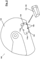
- the magnetic fastening device 100 may be used, for example, for fastening a communication unit 120, e.g. a Bluetooth ® communication unit, to a motorcycle helmet 122, either indirectly using a tray 124 mounted at the helmet 122 or directly (not shown).
- a communication unit 120 e.g. a Bluetooth ® communication unit
- the communication device 120 is an element of the first unit 102.
- the helmet 122 in the case of direct fastening to the helmet 122 or the tray 124 (in the case of indirect fastening) constitute or are part of the second unit 104 of the magnetic fastening device 100.
- the communication device 120 is fastened to a side surface 122a of the helmet 122, preferably in such a way that the wind forces exerted by the driving wind during a motorcycle ride support the maintenance of the form fit between protrusion 106 and recess 108.
- the magnetic fastening device 100 includes four protrusions 106 and two magnets 110a, 112a (shown in dotted lines as covered by the plastics material of the tray 124).
- the corresponding recesses and other magnets are not shown in Figure 2 as they are located at the lower side of the communication device 120.
- the afore-mentioned numbers are by no means intended to limit the scope of protection, and that a different number of protrusions and/or a different number of pairs of magnets may be used as well.
- the locations of the protrusions and/or magnets shown in Figure 2 are merely intended as examples, but by no means limiting the scope of protection.
- an electric connector 126 intended for connecting at least one microphone (not shown) and at least one loudspeaker (not shown) implemented in the helmet 122 to the communication device 120 may be provided on the tray 124.
- the connector 126 is merely an option, it is shown in dashed lines in Figure 2 .
- the tray 124 may be fixed to the helmet 122 by a clamp (not shown) which may permanently or releasably be fixed to the tray 124. It is, however, also conceivable to glue the tray 124 to the helmet 122, e.g. by using a strong double-sided tape.
- the protrusion may assume any suitable shape, e.g. the form of a thin and roundish pin or a rectangular protrusion or any other shape, as long as it fits into the recess.
Landscapes
- Engineering & Computer Science (AREA)
- General Engineering & Computer Science (AREA)
- Mechanical Engineering (AREA)
- Helmets And Other Head Coverings (AREA)
- Details Of Connecting Devices For Male And Female Coupling (AREA)
- Casings For Electric Apparatus (AREA)
- Clamps And Clips (AREA)
- Connection Of Plates (AREA)
Priority Applications (1)
| Application Number | Priority Date | Filing Date | Title |
|---|---|---|---|
| EP23157694.3A EP4201242A1 (fr) | 2020-11-05 | 2020-11-05 | Dispositif de fixation magnétique |
Applications Claiming Priority (3)
| Application Number | Priority Date | Filing Date | Title |
|---|---|---|---|
| EP20807886.5A EP4013256B1 (fr) | 2020-11-05 | 2020-11-05 | Dispositif de fixation magnétique |
| EP23157694.3A EP4201242A1 (fr) | 2020-11-05 | 2020-11-05 | Dispositif de fixation magnétique |
| PCT/IB2020/060404 WO2022096918A1 (fr) | 2020-11-05 | 2020-11-05 | Dispositif de fixation magnétique |
Related Parent Applications (1)
| Application Number | Title | Priority Date | Filing Date |
|---|---|---|---|
| EP20807886.5A Division EP4013256B1 (fr) | 2020-11-05 | 2020-11-05 | Dispositif de fixation magnétique |
Publications (1)
| Publication Number | Publication Date |
|---|---|
| EP4201242A1 true EP4201242A1 (fr) | 2023-06-28 |
Family
ID=73452241
Family Applications (3)
| Application Number | Title | Priority Date | Filing Date |
|---|---|---|---|
| EP23157694.3A Pending EP4201242A1 (fr) | 2020-11-05 | 2020-11-05 | Dispositif de fixation magnétique |
| EP20807886.5A Active EP4013256B1 (fr) | 2020-11-05 | 2020-11-05 | Dispositif de fixation magnétique |
| EP21802827.2A Active EP4240194B1 (fr) | 2020-11-05 | 2021-11-04 | Dispositif de fixation, équipement de protection de tête pourvu d'un tel dispositif de fixation |
Family Applications After (2)
| Application Number | Title | Priority Date | Filing Date |
|---|---|---|---|
| EP20807886.5A Active EP4013256B1 (fr) | 2020-11-05 | 2020-11-05 | Dispositif de fixation magnétique |
| EP21802827.2A Active EP4240194B1 (fr) | 2020-11-05 | 2021-11-04 | Dispositif de fixation, équipement de protection de tête pourvu d'un tel dispositif de fixation |
Country Status (6)
| Country | Link |
|---|---|
| US (6) | US12439993B2 (fr) |
| EP (3) | EP4201242A1 (fr) |
| JP (3) | JP7736788B2 (fr) |
| KR (2) | KR20250109785A (fr) |
| CN (2) | CN119073692B (fr) |
| WO (2) | WO2022096918A1 (fr) |
Families Citing this family (5)
| Publication number | Priority date | Publication date | Assignee | Title |
|---|---|---|---|---|
| US12287175B2 (en) * | 2020-08-21 | 2025-04-29 | Magne-Tech, Llc | Accessory mounts |
| EP4201242A1 (fr) * | 2020-11-05 | 2023-06-28 | Cardo Systems, Ltd. | Dispositif de fixation magnétique |
| DE102022132430A1 (de) | 2022-12-07 | 2024-06-13 | ABUS August Bremicker Söhne Kommanditgesellschaft | Modulares Helmsystem |
| DE102023123618A1 (de) * | 2023-09-01 | 2025-03-06 | Busch PROtective Germany GmbH & Co. KG | Befestigungssystem und Verfahren zum Arretieren und Ablösen eines ersten Verschlusselements an bzw. von einem zweiten Verschlusselement mittels eines Befestigungssystems |
| JP7809408B1 (ja) * | 2025-11-21 | 2026-02-02 | 株式会社サイン・ハウス | 無線通信装置及びインカム装置 |
Citations (3)
| Publication number | Priority date | Publication date | Assignee | Title |
|---|---|---|---|---|
| US20060133068A1 (en) | 2003-01-15 | 2006-06-22 | Sherring Paul D | Helmet mounted electroluminescent position indicator |
| US20150286117A1 (en) | 2014-04-07 | 2015-10-08 | Ermi, Inc. | Portable electronic device mounting system |
| US20170341871A1 (en) | 2016-05-31 | 2017-11-30 | MULTIPOND Wägetechnik GmbH | Connection device |
Family Cites Families (48)
| Publication number | Priority date | Publication date | Assignee | Title |
|---|---|---|---|---|
| US4521831A (en) | 1984-01-18 | 1985-06-04 | Thayer John R | Protective helmet with dual adjustment illumination means |
| ZA946001B (en) | 1993-08-11 | 1996-02-12 | Designodev Ltd | Flashlight adaptor |
| US5914816A (en) | 1997-11-04 | 1999-06-22 | Norotos, Inc. | Helmet mount for night vision goggle |
| US6101256A (en) * | 1997-12-29 | 2000-08-08 | Steelman; James A. | Self-contained helmet communication system |
| JP2002088559A (ja) * | 2000-09-13 | 2002-03-27 | Honda Motor Co Ltd | 通信機のヘルメット用装着具 |
| US6751810B1 (en) | 2003-03-13 | 2004-06-22 | Norotos, Inc. | Shroud plate |
| US7246384B2 (en) * | 2005-01-07 | 2007-07-24 | William George Bentz | Headgear and chin strap with magnetic fastener |
| JP5285764B2 (ja) | 2008-04-03 | 2013-09-11 | スリーエム イノベイティブ プロパティズ カンパニー | ヘッドギア用旋回アセンブリ |
| US8191180B2 (en) * | 2009-04-21 | 2012-06-05 | Bret Berry | Apparatus for preventing head or neck injury using magnetic assistance |
| US8371707B2 (en) | 2009-06-03 | 2013-02-12 | Robert Timothy Uzar | Portable light source |
| US8739313B2 (en) | 2009-11-20 | 2014-06-03 | Wilcox Industries Corp. | Helmet mounting systems |
| US20120002046A1 (en) | 2010-06-30 | 2012-01-05 | Raytheon Company | Flip-Up Hands-Free Display Mount |
| US8600094B2 (en) | 2011-01-20 | 2013-12-03 | Cardo Systems, Inc. | Mounting panel with elongated tongue |
| US10028543B2 (en) | 2011-01-31 | 2018-07-24 | Darryl William Munns | Safety light helmet |
| US20160174647A1 (en) | 2011-05-04 | 2016-06-23 | Frances H. Benton | Self-Closing Helmet Strap |
| TWM417024U (en) | 2011-06-20 | 2011-12-01 | Tai Sol Electronics Co Ltd | Warning light for use on helmet |
| FR2978904B1 (fr) | 2011-08-08 | 2014-07-25 | Remi Finiel | Ensemble casque et masque de protection oculaire |
| US8908389B2 (en) | 2011-10-07 | 2014-12-09 | Wilcox Industries Corp. | Power distribution system and helmet and method employing the same |
| US9622529B2 (en) | 2012-07-18 | 2017-04-18 | Wilcox Industries Corp. | Helmet edge trim wiring harness |
| EP2833754B1 (fr) * | 2012-12-14 | 2016-04-27 | Fidlock GmbH | Dispositif de fermeture pour relier deux pièces de manière détachable |
| US20140317890A1 (en) | 2013-04-24 | 2014-10-30 | Pacific Cycle, Llc | Helmet buckle with magnetic alignment |
| EP3013168B1 (fr) * | 2013-06-27 | 2019-11-13 | Revision Military S.à.r.l. | Système de montage pour casque |
| IL230802A0 (en) * | 2014-02-03 | 2014-09-30 | Cardo Systems Inc | Adapter for attaching an audio kit to the helmet |
| US10021931B2 (en) | 2014-04-02 | 2018-07-17 | Sopro Mounts Inc. | Helmet-chin mount for accessories, including cameras |
| US9726889B2 (en) | 2014-05-23 | 2017-08-08 | NUVIZ, Inc. | Helmet mounted display |
| US9756930B2 (en) | 2015-04-28 | 2017-09-12 | Axon Enterprise, Inc. | Methods and apparatus for a low-profile coupler |
| WO2017003930A1 (fr) | 2015-07-02 | 2017-01-05 | Frances Benton | Sangle de casque à fermeture automatique |
| US9829772B2 (en) | 2015-09-01 | 2017-11-28 | Gopro, Inc. | Removable camera mount for a helmet |
| US9507245B1 (en) | 2015-09-15 | 2016-11-29 | Gopro, Inc. | Detachable camera mount |
| US10026535B2 (en) * | 2015-12-31 | 2018-07-17 | Catch Latch, Llc | Mechanical magnetic connector structure |
| US10492559B1 (en) | 2016-09-12 | 2019-12-03 | Bell Sports, Inc. | Helmet with removable chin bar |
| NL2017522B1 (en) * | 2016-09-23 | 2018-04-04 | Crickd B V | Face guard, face guard receiving system and head protection system |
| CN106953657B (zh) | 2017-03-31 | 2023-03-31 | 汉得利(常州)电子股份有限公司 | 一种骨传导头盔通话装置 |
| TWI626899B (zh) | 2017-06-14 | 2018-06-21 | Zhang le yan | 頭盔 |
| DE102017212149A1 (de) * | 2017-07-14 | 2019-01-17 | Fidlock Gmbh | Verschlussvorrichtung mit elektrischem Kontakt |
| US11330857B2 (en) * | 2017-10-10 | 2022-05-17 | Wilcox Industries Corp. | Helmet mount interface apparatuses and methods |
| EP3479714B1 (fr) * | 2017-11-07 | 2020-06-03 | Locatelli S.p.A. | Casque de protection |
| IT201800007541A1 (it) | 2018-07-26 | 2020-01-26 | Nolangroup Spa | Casco di protezione con meccanismo di sollevamento/abbassamento della visiera |
| US10912344B2 (en) | 2018-12-03 | 2021-02-09 | Msa Technology, Llc | Helmet with accessory attachment rail |
| US11129431B2 (en) | 2019-05-07 | 2021-09-28 | Bell Sports, Inc. | Magnetic goggle attachment |
| US11213089B2 (en) | 2019-06-04 | 2022-01-04 | Msa Technology, Llc | Protective helmet with face protection shield and linkage mechanism |
| KR102209939B1 (ko) * | 2019-06-18 | 2021-02-01 | 주식회사 우진프라스틱 | 버클 |
| WO2021062308A1 (fr) * | 2019-09-25 | 2021-04-01 | Lexin Electronics Co., Ltd | Accessoire d'intercom bluetooth pour casques |
| EP4667036A3 (fr) | 2019-12-05 | 2026-01-21 | InteraXon Inc. | Dispositif portable |
| US12287175B2 (en) | 2020-08-21 | 2025-04-29 | Magne-Tech, Llc | Accessory mounts |
| EP4201242A1 (fr) * | 2020-11-05 | 2023-06-28 | Cardo Systems, Ltd. | Dispositif de fixation magnétique |
| CN114027582B (zh) | 2021-04-18 | 2023-09-15 | 联扬塑胶(深圳)有限公司 | 磁性扣具 |
| KR102740952B1 (ko) * | 2022-09-21 | 2024-12-10 | 아날로그플러스 주식회사 | 헬멧용 자석 버클 |
-
2020
- 2020-11-05 EP EP23157694.3A patent/EP4201242A1/fr active Pending
- 2020-11-05 WO PCT/IB2020/060404 patent/WO2022096918A1/fr not_active Ceased
- 2020-11-05 EP EP20807886.5A patent/EP4013256B1/fr active Active
-
2021
- 2021-11-04 KR KR1020257021993A patent/KR20250109785A/ko active Pending
- 2021-11-04 WO PCT/IB2021/060221 patent/WO2022097063A1/fr not_active Ceased
- 2021-11-04 KR KR1020237018766A patent/KR102832424B1/ko active Active
- 2021-11-04 CN CN202411125616.1A patent/CN119073692B/zh active Active
- 2021-11-04 CN CN202180089136.2A patent/CN116709943A/zh active Pending
- 2021-11-04 EP EP21802827.2A patent/EP4240194B1/fr active Active
- 2021-11-04 US US18/035,605 patent/US12439993B2/en active Active
- 2021-11-04 JP JP2023527094A patent/JP7736788B2/ja active Active
-
2022
- 2022-02-18 US US17/675,425 patent/US11484086B2/en active Active
- 2022-09-28 US US17/955,236 patent/US12102163B2/en active Active
-
2023
- 2023-10-13 US US18/486,829 patent/US12048344B2/en active Active
-
2024
- 2024-09-20 US US18/891,226 patent/US20250009064A1/en active Pending
-
2025
- 2025-02-12 US US19/051,778 patent/US12349758B2/en active Active
- 2025-07-03 JP JP2025113159A patent/JP2025158977A/ja active Pending
- 2025-08-28 JP JP2025142424A patent/JP2025184876A/ja active Pending
Patent Citations (3)
| Publication number | Priority date | Publication date | Assignee | Title |
|---|---|---|---|---|
| US20060133068A1 (en) | 2003-01-15 | 2006-06-22 | Sherring Paul D | Helmet mounted electroluminescent position indicator |
| US20150286117A1 (en) | 2014-04-07 | 2015-10-08 | Ermi, Inc. | Portable electronic device mounting system |
| US20170341871A1 (en) | 2016-05-31 | 2017-11-30 | MULTIPOND Wägetechnik GmbH | Connection device |
Also Published As
| Publication number | Publication date |
|---|---|
| US20250009064A1 (en) | 2025-01-09 |
| US20250176654A1 (en) | 2025-06-05 |
| EP4240194A1 (fr) | 2023-09-13 |
| KR20250109785A (ko) | 2025-07-17 |
| US12349758B2 (en) | 2025-07-08 |
| JP2025184876A (ja) | 2025-12-18 |
| CN116709943A (zh) | 2023-09-05 |
| US12048344B2 (en) | 2024-07-30 |
| US12102163B2 (en) | 2024-10-01 |
| EP4013256B1 (fr) | 2023-02-22 |
| US20240032638A1 (en) | 2024-02-01 |
| JP7736788B2 (ja) | 2025-09-09 |
| US11484086B2 (en) | 2022-11-01 |
| US20220218064A1 (en) | 2022-07-14 |
| CN119073692B (zh) | 2025-07-08 |
| JP2025158977A (ja) | 2025-10-17 |
| WO2022096918A1 (fr) | 2022-05-12 |
| JP2023548195A (ja) | 2023-11-15 |
| US12439993B2 (en) | 2025-10-14 |
| KR20230098850A (ko) | 2023-07-04 |
| CN119073692A (zh) | 2024-12-06 |
| EP4240194B1 (fr) | 2024-10-09 |
| KR102832424B1 (ko) | 2025-07-10 |
| WO2022097063A1 (fr) | 2022-05-12 |
| EP4013256A1 (fr) | 2022-06-22 |
| EP4240194C0 (fr) | 2024-10-09 |
| US20230404200A1 (en) | 2023-12-21 |
| US20230021199A1 (en) | 2023-01-19 |
Similar Documents
| Publication | Publication Date | Title |
|---|---|---|
| EP4013256B1 (fr) | Dispositif de fixation magnétique | |
| US6446372B1 (en) | Magnetic name plate assembly | |
| USD467269S1 (en) | Laser printable card badge sheet | |
| JP2012042956A (ja) | キータグ | |
| USD460783S1 (en) | Laser printable card badge sheet | |
| US7313410B2 (en) | Mobile phone and battery-releasing device thereof | |
| EP1177471B1 (fr) | Pince a ressort | |
| WO2002073269A3 (fr) | Couplage optique pour le montage d'une fibre optique sur un substrat | |
| CA2349070A1 (fr) | Godet d'encre pour impression en tampographie | |
| US7234958B1 (en) | Cable retention apparatus | |
| US20040198444A1 (en) | Mobile phone IC card holder | |
| EP2813744A1 (fr) | Dispositif de commande pour commande d'appel | |
| CA3274183C (fr) | Article de couvre-chef, pinces de montage et accessoires | |
| CN221081360U (zh) | 一种嵌入结构及带装饰物的保护壳 | |
| HK40100703B (en) | Fastening device, head-protective gear with such a fastening device | |
| HK40100703A (en) | Fastening device, head-protective gear with such a fastening device | |
| US7035402B2 (en) | Portable communication unit | |
| CN218415211U (zh) | 连接器 | |
| US20250219326A1 (en) | Connector | |
| CN119835356A (zh) | 一种嵌入结构及带装饰物的保护壳 | |
| KR20020062670A (ko) | 하우징을 구비한 전기 장치 | |
| US20220103919A1 (en) | Sound output device | |
| GB2624680A (en) | Article of headgear, mounting clips, and accessories | |
| WO1998056018A3 (fr) | Dispositifs inductifs plans | |
| CA3274183A1 (fr) | Article de couvre-chef, pinces de montage et accessoires |
Legal Events
| Date | Code | Title | Description |
|---|---|---|---|
| PUAI | Public reference made under article 153(3) epc to a published international application that has entered the european phase |
Free format text: ORIGINAL CODE: 0009012 |
|
| STAA | Information on the status of an ep patent application or granted ep patent |
Free format text: STATUS: REQUEST FOR EXAMINATION WAS MADE |
|
| 17P | Request for examination filed |
Effective date: 20230221 |
|
| AC | Divisional application: reference to earlier application |
Ref document number: 4013256 Country of ref document: EP Kind code of ref document: P |
|
| AK | Designated contracting states |
Kind code of ref document: A1 Designated state(s): AL AT BE BG CH CY CZ DE DK EE ES FI FR GB GR HR HU IE IS IT LI LT LU LV MC MK MT NL NO PL PT RO RS SE SI SK SM TR |
|
| STAA | Information on the status of an ep patent application or granted ep patent |
Free format text: STATUS: EXAMINATION IS IN PROGRESS |
|
| 17Q | First examination report despatched |
Effective date: 20250401 |
|
| RIC1 | Information provided on ipc code assigned before grant |
Ipc: A42B 3/04 20060101AFI20260306BHEP Ipc: F16B 1/00 20060101ALN20260306BHEP |