EP4201272B1 - Machine à café - Google Patents
Machine à café Download PDFInfo
- Publication number
- EP4201272B1 EP4201272B1 EP22771006.8A EP22771006A EP4201272B1 EP 4201272 B1 EP4201272 B1 EP 4201272B1 EP 22771006 A EP22771006 A EP 22771006A EP 4201272 B1 EP4201272 B1 EP 4201272B1
- Authority
- EP
- European Patent Office
- Prior art keywords
- unit
- grinder
- case body
- opening
- waste
- Prior art date
- Legal status (The legal status is an assumption and is not a legal conclusion. Google has not performed a legal analysis and makes no representation as to the accuracy of the status listed.)
- Active
Links
Images


Classifications
-
- A—HUMAN NECESSITIES
- A47—FURNITURE; DOMESTIC ARTICLES OR APPLIANCES; COFFEE MILLS; SPICE MILLS; SUCTION CLEANERS IN GENERAL
- A47J—KITCHEN EQUIPMENT; COFFEE MILLS; SPICE MILLS; APPARATUS FOR MAKING BEVERAGES
- A47J31/00—Apparatus for making beverages
- A47J31/42—Beverage-making apparatus with incorporated grinding or roasting means for coffee
-
- A—HUMAN NECESSITIES
- A47—FURNITURE; DOMESTIC ARTICLES OR APPLIANCES; COFFEE MILLS; SPICE MILLS; SUCTION CLEANERS IN GENERAL
- A47J—KITCHEN EQUIPMENT; COFFEE MILLS; SPICE MILLS; APPARATUS FOR MAKING BEVERAGES
- A47J31/00—Apparatus for making beverages
- A47J31/44—Parts or details or accessories of beverage-making apparatus
- A47J31/4403—Constructional details
-
- A—HUMAN NECESSITIES
- A47—FURNITURE; DOMESTIC ARTICLES OR APPLIANCES; COFFEE MILLS; SPICE MILLS; SUCTION CLEANERS IN GENERAL
- A47J—KITCHEN EQUIPMENT; COFFEE MILLS; SPICE MILLS; APPARATUS FOR MAKING BEVERAGES
- A47J42/00—Coffee mills; Spice mills
- A47J42/38—Parts or details
Definitions
- the present invention relates to a coffee machine according to the pre-characterizing part of claim 1.
- Patent Literature 1 A coffee machine that performs preparation using coffee beans has been proposed (for example, Patent Literature 1).
- the coffee machine proposed in Patent Literature 1 is equipped with a coffee bean grinding device (grinder) and a coffee beverage extraction device.
- an object of the present invention is to provide a coffee machine that is excellent in collecting wastes such as chaff and fine powder.
- the coffee machine according to the present invention for achieving the above object is a coffee machine according to claim 1.
- the coffee machine comprises
- the opening may allow the waste to pass therethrough or may allow an air flow to pass therethrough.
- the inner case body may be configured such that the air flow containing the waste swirls along the circumferential wall, the waste falls by an own weight thereof in the vicinity of the opening [for example, a one-dot chain line arrow shown in (b) of Figure 30], and an air flow [for example, a two-dot chain line arrow shown in (b) of Figure 30] is suctioned by the suction unit and rises, and the outer case body may store the waste [for example, the one-dot chain line arrow shown in (b) of Figure 30] fallen from the vicinity of the opening.
- the outer case body may be provided with a transparent portion.
- the inner case body may be provided with a transparent portion.
- a discharge unit configured to discharge air in the reservoir unit to an outside is provided above the reservoir unit.
- the grinder may include a first grinder and a second grinder, and the separation unit may be provided downstream of the first grinder and upstream of the second grinder.
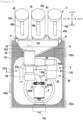
- FIG 1 is an external view of a beverage production device 1.
- the beverage production device 1 shown in Figure 1 is a device for automatically producing a coffee beverage from roasted coffee beans and a liquid (here, water), and can produce a coffee beverage for one cup per one production operation.
- Roasted coffee beans as a raw material can be accommodated in canisters 40.
- a cup placing portion 110 is provided in a lower portion of the beverage production device 1, and a produced coffee beverage is poured into a cup from a pouring portion 10c.
- the beverage production device 1 includes a housing 100 that forms an exterior of the beverage production device 1 and encloses an internal mechanism.
- the housing 100 is roughly divided into a main body portion 101 and a cover portion 102 that covers a part of a front surface and a part of a side surface of the beverage production device 1.
- the cover portion 102 is provided with an information display device 12.
- the information display device 12 shown in Figure 1 is a touch panel type display, and is capable of receiving an input from an administrator of the device or a beverage consumer in addition to displaying various types of information.
- the information display device 12 is attached to the cover portion 102 via a moving mechanism 12a, and can be moved in a predetermined range in an upper-lower direction by the moving mechanism 12a.
- the cover portion 102 is provided with a bean inlet 103 and an opening and closing door 103a that opens and closes the bean inlet 103.
- Roasted coffee beans different from the roasted coffee beans accommodated in the canister 40 can be input to the bean inlet 103 by opening the opening and closing door 103a. As a result, it is possible to provide a cup of special beverage to a beverage consumer.
- the cover portion 102 shown in Figure 1 is made of a translucent material such as acrylic or glass, and constitutes a transparent cover whose entire body is a transmissive portion. Therefore, an inner mechanism covered by the cover portion 102 can be visually recognized from the outside.
- a part of a production portion for producing a coffee beverage can be visually recognized through the cover portion 102.
- the main body portion 101 shown in Figure 1 is entirely a non-transmissive portion, and it is difficult to visually recognize the inside of the main body portion 101 from the outside.
- the housing 100 in a front portion of the beverage production device 1 has a double structure of the main body portion 101 and the cover portion 102 on an outer side (front side) of the main body portion 101.
- a part of mechanisms of the production portion are disposed between the main body portion 101 and the cover portion 102 in a front-rear direction, and can be visually recognized by a user through the cover portion 102.
- a part of the mechanisms of the production portion that can be visually recognized by a user through the cover portion 102 include a collective conveying portion 42, a first grinder 5A, a second grinder 5B, a separation device 6, an extraction container 9, and the like.
- a rectangular concave portion 101a recessed in a rear side is formed in a front portion of the main body portion 101, and the extraction container 9 and the like are positioned in a rear side of the concave portion 101a.
- a right end portion of the cover portion 102 is supported by the main body portion 101 via a hinge 102a so as to be freely opened and closed horizontally.
- An engaging portion 102b is provided at a left end portion of the cover portion 102 to maintain the main body portion 101 and the cover portion 102 in a closed state.
- the engaging portion 102b is, for example, a combination of a magnet and iron.
- the cover portion 102 shown in Figure 1 is of a horizontal opening type, but may be of a vertical opening type or a slide type. In addition, the cover portion 102 may be configured such that the cover portion 102 cannot be opened or closed.
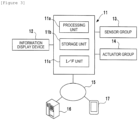
- FIG. 1 is a block diagram of the control device 11.
- the control device 11 controls the entire beverage production device 1.
- the control device 11 includes a processing unit 11a, a storage unit 11b, and an interface (I/F) unit 11c.
- the processing unit 11a is, for example, a processor such as a CPU.
- the storage unit 11b is, for example, a RAM or a ROM.
- the I/F unit 11c includes an input and output interface that inputs and outputs a signal between an external device and the processing unit 11a.
- the I/F unit 11c also includes a communication interface capable of performing data communication with a server 16 via a communication network 15 such as the Internet.
- the server 16 can communicate with a mobile terminal 17 such as a smartphone via the communication network 15, and can receive, for example, information such as a reservation for beverage production or an impression from the mobile terminal 17 of a beverage consumer.
- the processing unit 11a executes a program stored in the storage unit 11b, and controls an actuator group 14 based on an instruction from the information display device 12, a detection result of a sensor group 13, or an instruction from the server 16.
- the sensor group 13 includes various sensors (for example, a hot water temperature sensor, an operation position detection sensor of a mechanism, a pressure sensor) provided in the beverage production device 1.
- the actuator group 14 includes various actuators (for example, a motor, an electromagnetic valve, a heater, and the like) provided in the beverage production device 1.
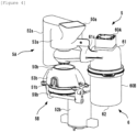
- the pulverizing device 5 described here has a different appearance from that of the pulverizing device shown in Figure 2 , but has the same function.
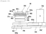
- Figure 4 is a perspective view of the pulverizing device 5
- Figure 5 is a longitudinal cross-sectional view of the pulverizing device 5 shown in Figure 4 .
- the pulverizing device 5 shown in Figure 4 also includes the first grinder 5A, the second grinder 5B, and the separation device 6.
- the first grinder 5A and the second grinder 5B are mechanisms for grinding roasted coffee beans supplied from the reservoir device 4 shown in Figure 2 .
- the first grinder 5A is a grinder for crushing coffee beans into a predetermined size (for example, about 1/4) to facilitate separation of wastes adhering to the coffee beans.
- the second grinder 5B is a grinder for grinding the coffee beans crushed by the first grinder 5A into ground coffee beans having a desired particle size.
- the first grinder 5A and the second grinder 5B have different particle sizes for grinding beans, and the second grinder 5B is a grinder having a finer particle size than the first grinder 5A.
- the particle size of the ground beans in the second grinder 5B may have an error (about ⁇ 5 ⁇ m), but can be adjusted by adjusting an interval between a rotary blade 58b and a fixed blade 57b.
- the first grinder 5A includes a motor 52a (see Figure 4 ) and a main body portion 53a.
- the motor 52a is a drive source of the first grinder 5A.
- the main body portion 53a is a unit for accommodating a cutter, and includes a built-in rotation shaft 54a as shown in Figure 5 .
- a gear 55a is provided on the rotation shaft 54a, and a driving force of the motor 52a is transmitted to the rotation shaft 54a via the gear 55a.
- a rotary blade 58a which is a cutter
- a fixed blade 57a which is a cutter
- the inside of the main body portion 53a communicates with an inlet 50a (see Figure 4 ) and a discharge port 51a (see Figure 5 ).
- Roasted coffee beans supplied from the reservoir device 4 shown in Figure 2 enter the main body portion 53a from the inlet 50a formed in an upper portion of the main body portion 53a, and are pulverized while being sandwiched between the rotary blade 58a and the fixed blade 57a shown in Figure 5 .
- Roasted coffee beans supplied to the inlet 50a may be supplied not from above the rotary blade 58a but at a height at which the roasted coffee beans come into contact with a side surface of the rotary blade 58a. In this case, since the roasted coffee beans are prevented from escaping to the upper side by the rotary blade 58a, the preventing plate 56a may not be provided.
- the separation device 6 shown in Figure 4 is a mechanism that is disposed between the first grinder 5A and the second grinder 5B and separates wastes such as chaff and fine powder from ground beans by an air suction force.
- Roasted coffee beans supplied from the reservoir device 4 are first coarsely ground by the first grinder 5A, and wastes are separated from the coarsely ground beans by the separation device 6.
- the coarsely ground beans from which the wastes are separated are finely ground by the second grinder 5B.
- the second grinder 5B includes a motor 52b (see Figure 4 ) and a main body portion 53b.
- the motor 52b is a drive source of the second grinder 5B.
- the main body portion 53b is a unit for accommodating a cutter, and includes a built-in rotation shaft 54b as shown in Figure 5 .
- a pulley 55b is provided on the rotation shaft 54b, and a driving force of the motor 52b is transmitted to the rotation shaft 54b via a belt 59b and the pulley 55b.
- the rotary blade 58b is provided on the rotation shaft 54b, and the fixed blade 57b is provided on an upper side of the rotary blade 58b.
- the inside of the main body portion 53b communicates with the inlet 50b shown in Figure 4 and the discharge port 51b shown in Figure 4 .
- Ground beans falling from the separation device 6 enter the main body portion 53b from the inlet 50b, and are further pulverized while being sandwiched between the rotary blade 58b and the fixed blade 57b.
- the ground beans pulverized into powder are discharged from the discharge port 51b.
- a particle size of the ground beans in the second grinder 5B can be adjusted by adjusting the interval between the rotary blade 58b and the fixed blade 57b.
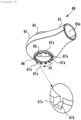
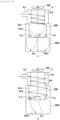
- the collection container 60B includes the upper portion 61 and the lower portion 62 that are engaged with each other in a separable manner.
- the lower portion 62 has a bottomed cylindrical shape with an open upper side, and forms a space for accumulating wastes.
- the upper portion 61 constitutes a lid portion to be attached to an opening of the lower portion 62.
- the upper portion 61 includes the cylindrical outer circumferential wall 61a and the exhaust pipe 61b formed coaxially with the outer circumferential wall 61a.
- the air blowing unit 60A is fixed to the upper portion 61 above the exhaust pipe 61b so as to suction the air in the exhaust pipe 61b.
- the upper portion 61 includes a tubular connecting portion 61c extending in a radial direction.
- the connecting portion 61c is connected to the forming unit 6B, and allows the separation chamber SC to communicate with the collection container 60B.
- the connecting portion 61c is open to the side of the exhaust pipe 61b.
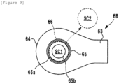
- the forming unit 6B shown in Figure 7 is formed by combining two members divided into upper and lower halves.
- the forming unit 6B includes a pipe portion 63 and a separation chamber forming portion 64, and has a spoon shape in a plan view.
- the pipe portion 63 is a cylindrical body that forms a communication passage 63a with the suction unit 6A, and extends in the lateral direction (a direction intersecting a center line CL to be described later).
- the separation chamber forming portion 64 is an annular hollow body that is connected to the pipe portion 63, forms the separation chamber SC, and has an opening at the center in the upper-lower direction.
- the separation chamber forming portion 64 shown in Figure 7 includes a cylindrical portion 65 extending in the upper-lower direction.
- the cylindrical portion 65 protrudes into the separation chamber SC from a central portion in the upper-lower direction to a lower portion thereof.
- the cylindrical portion 65 includes an opening portion 65a at one end on an upper side, and the opening portion 65a forms an inlet of ground beans communicating with the separation chamber SC.
- the opening portion 65a is positioned outside the separation chamber SC and is connected to the discharge port 51a (see Figure 5 ) of the first grinder 5A. As a result, ground beans falling from the discharge port 51a are introduced into the separation chamber forming portion 64 without leaking.
- the cylindrical portion 65 includes an opening portion 65b at the other end on a lower side.
- the opening portion 65b is positioned in the separation chamber SC. Since the opening portion 65b faces the separation chamber SC, ground beans falling from the discharge port 51a are introduced into the separation chamber SC without leaking.
- the cylindrical portion 65 has a cylindrical shape, and the opening portion 65a and the opening portion 65b have a concentric circular shape positioned on the center line CL. As a result, the ground beans falling from the discharge port 51a easily pass through the cylindrical portion 65.
- the cylindrical portion 65 has a tapered shape in which a cross-sectional area of an internal space gradually decreases from the opening portion 65a side toward the opening portion 65b side. Since an inner wall of the cylindrical portion 65 has a mortar shape, the falling ground beans easily collide with the inner wall. In some cases, the ground beans falling from the first grinder 5A adhere to each other and fall as a lump. When the ground beans are in the form of a lump, the separation efficiency of wastes may decrease. In the cylindrical portion 65 shown in Figure 7 , the lump of ground beans collides with the inner wall of the cylindrical portion 65, thereby breaking the lump and making it easier to separate wastes.
- the inner wall of the cylindrical portion 65 is not limited to a mortar shape in terms of breaking the lump of ground beans.
- the cylindrical portion 65 does not have to protrude into the separation chamber SC, and may include only a portion protruding upward from an outer surface of the separation chamber forming portion 64.
- a wind speed around the cylindrical portion 65 can be improved. Therefore, in a region R1 relatively far from the pipe portion 63, an effect of separating wastes due to the wind pressure can be enhanced.
- the separation chamber forming portion 64 includes a discharge port 66 communicating with the separation chamber SC, from which the ground beans are discharged after wastes are separated.
- the discharge port 66 shown in Figure 7 is positioned below the opening portion 65b, and the ground beans having passed through the cylindrical portion 65 pass through the separation chamber SC and fall freely from the discharge port 66.
- the discharge port 66 is a circular opening positioned on the center line CL, and is an opening concentric with the opening portion 65a and the opening portion 65b. Therefore, the ground beans easily pass through the separation chamber forming portion 64 by free fall, and it is possible to prevent the ground beans from accumulating in the separation chamber forming portion 64.
- a cross-sectional area SC2 of the discharge port 66 is larger than a cross-sectional area SC1 of the opening portion 65b.
- the opening portion 65b and the discharge port 66 overlap each other when viewed in the upper-lower direction. Therefore, when the opening portion 65b is projected in the upper-lower direction with respect to the discharge port 66, the opening portion 65b is accommodated inside the discharge port 66. In other words, the opening portion 65b is accommodated in a region in which the discharge port 66 is extended in the upper-lower direction. It is also possible to adopt a configuration in which the opening portion 65b and the discharge port 66 are not on the same center line but overlap each other, or a configuration in which at least one of the opening portion 65b or the discharge port 66 is not circular but is overlapped.
- a ratio of the cross-sectional area SC1 to the cross-sectional area SC2 is, for example, 95% or less, or 85% or less, and is, for example, 60% or more or 70% or more. Since the opening portion 65b and the discharge port 66 are concentric, the opening portion 65b and the discharge port 66 overlap each other when viewed in the direction of the center line CL. Therefore, ground beans falling freely from the opening portion 65b are easily discharged from the discharge port 66. In addition, it is possible to prevent the falling ground beans from colliding with an edge of the discharge port 66 and jumping to the pipe portion 63 side, and it is also possible to prevent the required ground beans from being suctioned to the suction unit 6A.
- an opening area of the opening portion on one end is smaller than an opening area of the discharge port (for example, 66)
- the opening area of the discharge port (for example, 66) and the opening area of the opening portion on one end may be the same, or the opening area of the opening portion on one end (for example, 65a) may be larger than the opening area of the discharge port (for example, 66).
- an opening area of the opening portion on the other end (for example, 65b) is smaller than the opening area of the discharge port (for example, 66)
- the opening area of the discharge port (for example, 66) and the opening area of the opening portion on the other end may be the same, or the opening area of the opening portion on the other end (for example, 65b) may be larger than the opening area of the discharge port (for example, 66).
- an amount of air suctioned from the discharge port 66 may be larger than an amount of air suctioned from the inlets (for example, 65a and 65a').
- any one of inner wall portions of members (63 to 65) constituting the forming unit 6B and the separation chamber SC, the cylindrical portion 65, or the opening portion on the other end (for example, 65b) may vibrate by being in contact with the grinder (at least one of 5A or 5B) directly or indirectly via another member to receive the vibration due to rotation of the grinder.
- the forming unit 6B like the coffee bean grinding machine 1 in the embodiment, is in direct contact with the first grinder 5A out of the first grinder 5A and the second grinder 5B, and by bringing the forming unit 6B into direct contact with one grinder in this way, appropriate vibration may be applied to the forming unit 6B to facilitate the suction of light wastes.
- the air suctioned by the suction unit 6A is mainly suctioned through the discharge port 66. Therefore, as shown in Figure 5 , a gap is provided between the discharge port 66 and the inlet 50b of the second grinder 5B, and air suction is facilitated.
- An arrow d4 shown in Figure 7 schematically indicates a direction of an air flow of the air suctioned by the suction unit 6A. Suction of air from the discharge port 66 makes it difficult for wastes to be discharged from the discharge port 66, and separation performance between ground beans and wastes can be improved.
- the air suctioned by the suction unit 6A is also suctioned through the opening portion 65a.
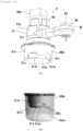
- a turbulent flow generating portion 67 is formed in a surrounding wall defining the discharge port 66.
- the turbulent flow generating portion 67 generates a turbulent flow in the air suctioned from the discharge port 66 into the separation chamber SC.
- a turbulent flow is particularly likely to occur in a region R2 between the opening portion 65b and the discharge port 66.
- the generation of the turbulent flow in the region R2 can be synergistically facilitated.
- Ground beans put into the inlet 65a are stirred by being affected by the turbulent flow when passing through the region R2.
- the cross-sectional area SC2 of the discharge port 66 is larger than the cross-sectional area SC1 of the opening portion 65b, the ground beans always pass through the region R2. Due to the turbulent flow, wastes such as chaff and fine powder are easily separated from the ground beans. Therefore, even if the separation chamber SC is a small space, it is possible to improve the separation efficiency of the wastes, and in particular, it contributes to reducing a length of the separation chamber SC in the upper-lower direction, which is advantageous in reducing the size of the device when two-stage pulverizing is performed by the first grinder 5A and the second grinder 5B.
- the turbulent flow generating portion 67 includes a plurality of turbulent flow generating elements 67a.
- the turbulent flow generating element 67a is a protrusion protruding downward in the upper-lower direction.
- a direction in which the turbulent flow generating element 67a protrudes may be any direction, but a direction within a range from a lower direction to a radially inward direction is preferable in terms of facilitating the generation of a turbulent flow in the separation chamber SC.
- the protruding direction is the lower direction, the falling ground beans are not caught, which is more preferable.
- a cross-sectional shape of the turbulent flow generating element 67a is such that an upper base of a cross section of a quadrangular prism having a trapezoidal shape is oriented in the direction of the center line CL, and, as shown in Figure 8 , an inner side of a tip end portion is provided with a chamfer 67b.
- the shape of the turbulent flow generating element 67a is not limited thereto, but a shape that makes a shape of the discharge port 66 three-dimensionally complicated is preferable.
- the turbulent flow generating element 67a is repeatedly formed in a circumferential direction d5 of the discharge port 66. As a result, air is blown into the region R2 from multiple directions, which facilitates the generation of a turbulent flow. Adjacent turbulent flow generating elements 67a have the same pitch, but may have different pitches. Although twelve turbulent flow generating elements 67a are formed, the number of the turbulent flow generating elements 67a is any number.
- the pulverizing device 5 described with reference to Figures 12 to 17 is to be incorporated in the beverage production device 1 shown in Figure 1
- the pulverizing device 5 alone can also be used as a coffee bean grinding machine.
- a reservoir device that accommodates roasted coffee beans and supplies the coffee beans to the inlet 50a, a control device that controls the pulverizing device 5, and an information display device are added.
- Figure 10 is an external perspective view of a coffee bean grinding machine
- Figure 11 is a block diagram of a control device of the coffee bean grinding machine.
- a basic configuration of the coffee bean grinding machine shown in Figure 10 is substantially the same as a basic configuration of the pulverizing device 5 described with reference to Figures 12 to 17 .
- components having the same names as those described above are denoted by the same reference numerals as those used above, and differences from the pulverizing device 5 described with reference to Figures 12 to 17 will be mainly described.
- a coffee bean grinding machine GM shown in Figure 10 includes the reservoir device 4, the pulverizing device 5, and the control device 11 shown in Figure 11 that controls the reservoir device 4 and the pulverizing device 5.
- the coffee bean grinding machine GM also includes the information display device 12 (see Figure 11 ) wirelessly connected to the control device 11.
- the information display device 12 is a touch panel type display for inputting various control instructions, set values, and the like of the coffee bean grinding machine GM, and can receive inputs from an administrator or a user in addition to displaying various types of information.
- the information display device 12 is provided with a speaker and a camera.
- the control device 11 controls the entire coffee bean grinding machine GM.
- the control device 11 includes the processing unit 11a, the storage unit 11b, and the interface (I/F) unit 11c.
- the processing unit 11a is, for example, a processor such as a CPU.
- the storage unit 11b is, for example, a RAM or a ROM.
- a recipe is stored in the storage unit 11b.
- the recipe includes information on various conditions for grinding coffee beans, beans information, recipe creator information, comments of a recipe creator, and the like.
- the I/F unit 11c includes an input and output interface that inputs and outputs a signal between an external device and the processing unit 11a.
Landscapes
- Engineering & Computer Science (AREA)
- Food Science & Technology (AREA)
- Apparatus For Making Beverages (AREA)
- Tea And Coffee (AREA)
Claims (4)
- Machine à café (1) comprenant :un moulin (5a, 5b) conçu pour moudre des grains de café ;une unité de séparation (6B) conçue pour séparer un déchet des grains de café ;une unité de réservoir (60B) constituée d'une partie supérieure (61) avec un tuyau d'échappement (61b) à l'intérieur et d'une partie inférieure (62), et conçue pour stocker les déchets séparés des grains de café dans l'unité de séparation (6B),une unité d'aspiration (60A) comportant un moteur de ventilateur disposé au-dessus de l'unité de réservoir (60B), dans laquelle ;l'unité d'aspiration (60A) est configurée pour envoyer un flux d'air contenant les déchets de l'unité de séparation (6B) à l'intérieur de la partie supérieure (61) de l'unité de réservoir (60B) par aspiration causée par la rotation du moteur de ventilateur,le tuyau d'échappement (61b) est conçu pour avoir le flux d'air contenant les déchets envoyé depuis l'unité de séparation (6B) et pour tourbillonner vers le bas autour du tuyau d'échappement (61b),caractérisé en ce que la partie inférieure (62) de l'unité de réservoir (60B) comporte un corps de boîtier externe (60Bo) et un corps de boîtier interne (60Bi) qui se trouve à l'intérieur du corps de boîtier externe,le corps du boîtier interne (60Bi) a une surface inférieure (6ibs) et une paroi latérale circonférentielle (6iw), et une ouverture (6io) reliée à l'intérieur du corps de boîtier externe dans la paroi latérale circonférentielle,le corps de boîtier interne (60Bi) est conçu de telle sorte qu'un flux d'air contenant les déchets tourbillonnant vers le bas autour du tuyau d'échappement (61b) pénètre à l'intérieur de la paroi latérale circonférentielle (6iw), et ensuite les déchets tombent en raison de leur poids à l'intérieur de la paroi latérale circonférentielle, et un flux d'air est aspiré par l'unité d'aspiration (60A) et s'élève depuis l'intérieur du tuyau d'échappement (61b), les déchets passant à travers l'ouverture (6io),le corps du boîtier externe (60Bo) stocke les déchets passés par l'ouverture (6io).
- Machine à café (1) selon la revendication 1, dans laquelle
le corps du boîtier externe (60Bo) est pourvu d'une partie transparente. - Machine à café (1) selon la revendication 1 ou 2, dans laquelle
le corps de boîtier interne (60Bi) est pourvu d'une partie transparente. - Machine à café (1) selon la revendication 1, dans laquelle ;
une unité d'évacuation est conçue pour évacuer l'air dans l'unité de réservoir (60B) vers l'extérieur, au-dessus de l'unité de réservoir.
Applications Claiming Priority (2)
| Application Number | Priority Date | Filing Date | Title |
|---|---|---|---|
| JP2021045961A JP7112131B1 (ja) | 2021-03-19 | 2021-03-19 | コーヒーマシン |
| PCT/JP2022/006675 WO2022196247A1 (fr) | 2021-03-19 | 2022-02-18 | Machine à café |
Publications (4)
| Publication Number | Publication Date |
|---|---|
| EP4201272A1 EP4201272A1 (fr) | 2023-06-28 |
| EP4201272A4 EP4201272A4 (fr) | 2024-01-10 |
| EP4201272B1 true EP4201272B1 (fr) | 2024-12-25 |
| EP4201272C0 EP4201272C0 (fr) | 2024-12-25 |
Family
ID=82701539
Family Applications (1)
| Application Number | Title | Priority Date | Filing Date |
|---|---|---|---|
| EP22771006.8A Active EP4201272B1 (fr) | 2021-03-19 | 2022-02-18 | Machine à café |
Country Status (9)
| Country | Link |
|---|---|
| US (1) | US11871868B2 (fr) |
| EP (1) | EP4201272B1 (fr) |
| JP (1) | JP7112131B1 (fr) |
| KR (1) | KR102579000B1 (fr) |
| CN (1) | CN116075249B (fr) |
| CA (1) | CA3194178C (fr) |
| ES (1) | ES3015208T3 (fr) |
| TW (1) | TWI819525B (fr) |
| WO (1) | WO2022196247A1 (fr) |
Families Citing this family (4)
| Publication number | Priority date | Publication date | Assignee | Title |
|---|---|---|---|---|
| DE102018007750A1 (de) * | 2018-10-02 | 2020-04-02 | Spengler Gmbh & Co. Kg | Verfahren zur Ausgabe eines Heißgetränks |
| US12369744B1 (en) | 2024-01-18 | 2025-07-29 | Sharkninja Operating Llc | Preparation of beverage machines for cold beverage brewing |
| US12575692B2 (en) | 2024-01-18 | 2026-03-17 | Sharkninja Operating Llc | Suggesting coffee bean grind size for beverage machines |
| WO2025155323A1 (fr) | 2024-01-18 | 2025-07-24 | Sharkninja Operating Llc | Prévention du blocage du broyeur de grains de café |
Family Cites Families (13)
| Publication number | Priority date | Publication date | Assignee | Title |
|---|---|---|---|---|
| JP2597731Y2 (ja) * | 1991-07-17 | 1999-07-12 | 睦男 田中 | 全自動コーヒー抽出装置 |
| JPH07250619A (ja) * | 1994-01-28 | 1995-10-03 | Haatec:Kk | コーヒーのチャフ除去装置 |
| KR200310767Y1 (ko) * | 2003-01-22 | 2003-04-16 | 주식회사 유니코사이버컴 | 자동 두부제조장치 |
| US8327754B2 (en) * | 2003-07-22 | 2012-12-11 | The Coca-Cola Company | Coffee and tea pod |
| TWI432162B (zh) * | 2011-07-26 | 2014-04-01 | 李秉諺 | A coffee bean grinder with a stripping function |
| JP2013066697A (ja) * | 2011-09-05 | 2013-04-18 | Toru Imai | 破砕コーヒー豆の渋皮(チャフ)及び微粉除去装置 |
| GB2531686B (en) * | 2015-11-25 | 2016-09-07 | Cambdev Ltd | Coffee dispensing apparatus |
| CN107042203A (zh) * | 2017-02-06 | 2017-08-15 | 郑州蓝山咖啡机械科技有限公司 | 风送式咖啡豆除石机 |
| JP6480525B2 (ja) | 2017-08-07 | 2019-03-13 | 株式会社Tree Field | 飲料製造装置 |
| ES2992518T3 (es) * | 2017-08-07 | 2024-12-13 | Daito Giken Inc | Aparato de separación, aparato de molienda y aparato de producción de bebidas |
| JP7052983B6 (ja) | 2017-08-07 | 2022-07-15 | 株式会社大都技研 | 粉砕装置及び飲料製造装置 |
| KR101981334B1 (ko) | 2017-09-14 | 2019-05-22 | 에스케이텔레콤 주식회사 | 분산형 데이터 패킷 처리가 적용된 이동통신 시스템 및 방법 |
| KR102012808B1 (ko) * | 2018-03-22 | 2019-08-21 | (주)청류에프앤에스 | 원두로스터용 제연장치 |
-
2021
- 2021-03-19 JP JP2021045961A patent/JP7112131B1/ja active Active
-
2022
- 2022-02-18 ES ES22771006T patent/ES3015208T3/es active Active
- 2022-02-18 CN CN202280006048.6A patent/CN116075249B/zh active Active
- 2022-02-18 KR KR1020237002127A patent/KR102579000B1/ko active Active
- 2022-02-18 CA CA3194178A patent/CA3194178C/fr active Active
- 2022-02-18 US US18/025,143 patent/US11871868B2/en active Active
- 2022-02-18 WO PCT/JP2022/006675 patent/WO2022196247A1/fr not_active Ceased
- 2022-02-18 EP EP22771006.8A patent/EP4201272B1/fr active Active
- 2022-03-16 TW TW111109682A patent/TWI819525B/zh active
Also Published As
| Publication number | Publication date |
|---|---|
| JP7112131B1 (ja) | 2022-08-03 |
| TW202243633A (zh) | 2022-11-16 |
| KR102579000B1 (ko) | 2023-09-14 |
| CA3194178C (fr) | 2025-05-06 |
| KR20230017363A (ko) | 2023-02-03 |
| EP4201272A1 (fr) | 2023-06-28 |
| CA3194178A1 (fr) | 2022-09-22 |
| CN116075249A (zh) | 2023-05-05 |
| WO2022196247A1 (fr) | 2022-09-22 |
| TWI819525B (zh) | 2023-10-21 |
| CN116075249B (zh) | 2023-08-18 |
| JP2022144796A (ja) | 2022-10-03 |
| ES3015208T3 (en) | 2025-04-30 |
| EP4201272C0 (fr) | 2024-12-25 |
| EP4201272A4 (fr) | 2024-01-10 |
| US11871868B2 (en) | 2024-01-16 |
| US20230240469A1 (en) | 2023-08-03 |
Similar Documents
| Publication | Publication Date | Title |
|---|---|---|
| EP4201272B1 (fr) | Machine à café | |
| EP4209153B1 (fr) | Machine à café | |
| JP7158066B2 (ja) | コーヒーマシン | |
| KR102629344B1 (ko) | 커피머신 | |
| EP4258230A1 (fr) | Dispositif de mouture de grains de café | |
| JP7785405B2 (ja) | コーヒーマシン | |
| WO2023100972A1 (fr) | Machine à café | |
| EP4258231A1 (fr) | Appareil de broyage de grains de café | |
| JP2022144798A (ja) | コーヒー豆挽き機 | |
| JP2022144794A (ja) | コーヒー豆挽き機 | |
| JP7716798B1 (ja) | コーヒーマシン | |
| JP7282422B2 (ja) | コーヒーマシン | |
| WO2022196248A1 (fr) | Machine à café | |
| JP2022144793A (ja) | コーヒー豆挽き機 | |
| JP2022144792A (ja) | コーヒー豆挽き機 |
Legal Events
| Date | Code | Title | Description |
|---|---|---|---|
| STAA | Information on the status of an ep patent application or granted ep patent |
Free format text: STATUS: THE INTERNATIONAL PUBLICATION HAS BEEN MADE |
|
| PUAI | Public reference made under article 153(3) epc to a published international application that has entered the european phase |
Free format text: ORIGINAL CODE: 0009012 |
|
| STAA | Information on the status of an ep patent application or granted ep patent |
Free format text: STATUS: REQUEST FOR EXAMINATION WAS MADE |
|
| 17P | Request for examination filed |
Effective date: 20230320 |
|
| AK | Designated contracting states |
Kind code of ref document: A1 Designated state(s): AL AT BE BG CH CY CZ DE DK EE ES FI FR GB GR HR HU IE IS IT LI LT LU LV MC MK MT NL NO PL PT RO RS SE SI SK SM TR |
|
| A4 | Supplementary search report drawn up and despatched |
Effective date: 20231213 |
|
| RIC1 | Information provided on ipc code assigned before grant |
Ipc: A47J 31/44 20060101ALN20231207BHEP Ipc: A47J 42/38 20060101ALN20231207BHEP Ipc: A47J 31/42 20060101AFI20231207BHEP |
|
| DAV | Request for validation of the european patent (deleted) | ||
| DAX | Request for extension of the european patent (deleted) | ||
| GRAP | Despatch of communication of intention to grant a patent |
Free format text: ORIGINAL CODE: EPIDOSNIGR1 |
|
| STAA | Information on the status of an ep patent application or granted ep patent |
Free format text: STATUS: GRANT OF PATENT IS INTENDED |
|
| RIC1 | Information provided on ipc code assigned before grant |
Ipc: A47J 31/44 20060101ALN20240613BHEP Ipc: A47J 42/38 20060101ALN20240613BHEP Ipc: A47J 31/42 20060101AFI20240613BHEP |
|
| RIC1 | Information provided on ipc code assigned before grant |
Ipc: A47J 31/44 20060101ALN20240627BHEP Ipc: A47J 42/38 20060101ALN20240627BHEP Ipc: A47J 31/42 20060101AFI20240627BHEP |
|
| INTG | Intention to grant announced |
Effective date: 20240717 |
|
| GRAS | Grant fee paid |
Free format text: ORIGINAL CODE: EPIDOSNIGR3 |
|
| GRAA | (expected) grant |
Free format text: ORIGINAL CODE: 0009210 |
|
| STAA | Information on the status of an ep patent application or granted ep patent |
Free format text: STATUS: THE PATENT HAS BEEN GRANTED |
|
| AK | Designated contracting states |
Kind code of ref document: B1 Designated state(s): AL AT BE BG CH CY CZ DE DK EE ES FI FR GB GR HR HU IE IS IT LI LT LU LV MC MK MT NL NO PL PT RO RS SE SI SK SM TR |
|
| REG | Reference to a national code |
Ref country code: GB Ref legal event code: FG4D |
|
| REG | Reference to a national code |
Ref country code: CH Ref legal event code: EP |
|
| REG | Reference to a national code |
Ref country code: DE Ref legal event code: R096 Ref document number: 602022009167 Country of ref document: DE |
|
| REG | Reference to a national code |
Ref country code: IE Ref legal event code: FG4D |
|
| U01 | Request for unitary effect filed |
Effective date: 20250121 |
|
| U07 | Unitary effect registered |
Designated state(s): AT BE BG DE DK EE FI FR IT LT LU LV MT NL PT RO SE SI Effective date: 20250127 |
|
| U20 | Renewal fee for the european patent with unitary effect paid |
Year of fee payment: 4 Effective date: 20250221 |
|
| PG25 | Lapsed in a contracting state [announced via postgrant information from national office to epo] |
Ref country code: NO Free format text: LAPSE BECAUSE OF FAILURE TO SUBMIT A TRANSLATION OF THE DESCRIPTION OR TO PAY THE FEE WITHIN THE PRESCRIBED TIME-LIMIT Effective date: 20250325 |
|
| PG25 | Lapsed in a contracting state [announced via postgrant information from national office to epo] |
Ref country code: GR Free format text: LAPSE BECAUSE OF FAILURE TO SUBMIT A TRANSLATION OF THE DESCRIPTION OR TO PAY THE FEE WITHIN THE PRESCRIBED TIME-LIMIT Effective date: 20250326 |
|
| PG25 | Lapsed in a contracting state [announced via postgrant information from national office to epo] |
Ref country code: RS Free format text: LAPSE BECAUSE OF FAILURE TO SUBMIT A TRANSLATION OF THE DESCRIPTION OR TO PAY THE FEE WITHIN THE PRESCRIBED TIME-LIMIT Effective date: 20250325 |
|
| REG | Reference to a national code |
Ref country code: ES Ref legal event code: FG2A Ref document number: 3015208 Country of ref document: ES Kind code of ref document: T3 Effective date: 20250430 |
|
| PG25 | Lapsed in a contracting state [announced via postgrant information from national office to epo] |
Ref country code: SM Free format text: LAPSE BECAUSE OF FAILURE TO SUBMIT A TRANSLATION OF THE DESCRIPTION OR TO PAY THE FEE WITHIN THE PRESCRIBED TIME-LIMIT Effective date: 20241225 |
|
| PG25 | Lapsed in a contracting state [announced via postgrant information from national office to epo] |
Ref country code: PL Free format text: LAPSE BECAUSE OF FAILURE TO SUBMIT A TRANSLATION OF THE DESCRIPTION OR TO PAY THE FEE WITHIN THE PRESCRIBED TIME-LIMIT Effective date: 20241225 |
|
| PGFP | Annual fee paid to national office [announced via postgrant information from national office to epo] |
Ref country code: ES Payment date: 20250331 Year of fee payment: 4 |
|
| PG25 | Lapsed in a contracting state [announced via postgrant information from national office to epo] |
Ref country code: IS Free format text: LAPSE BECAUSE OF FAILURE TO SUBMIT A TRANSLATION OF THE DESCRIPTION OR TO PAY THE FEE WITHIN THE PRESCRIBED TIME-LIMIT Effective date: 20250425 |
|
| PG25 | Lapsed in a contracting state [announced via postgrant information from national office to epo] |
Ref country code: SK Free format text: LAPSE BECAUSE OF FAILURE TO SUBMIT A TRANSLATION OF THE DESCRIPTION OR TO PAY THE FEE WITHIN THE PRESCRIBED TIME-LIMIT Effective date: 20241225 |
|
| PG25 | Lapsed in a contracting state [announced via postgrant information from national office to epo] |
Ref country code: CZ Free format text: LAPSE BECAUSE OF FAILURE TO SUBMIT A TRANSLATION OF THE DESCRIPTION OR TO PAY THE FEE WITHIN THE PRESCRIBED TIME-LIMIT Effective date: 20241225 |
|
| PG25 | Lapsed in a contracting state [announced via postgrant information from national office to epo] |
Ref country code: MC Free format text: LAPSE BECAUSE OF FAILURE TO SUBMIT A TRANSLATION OF THE DESCRIPTION OR TO PAY THE FEE WITHIN THE PRESCRIBED TIME-LIMIT Effective date: 20241225 |
|
| RAP2 | Party data changed (patent owner data changed or rights of a patent transferred) |
Owner name: DAITO ENTERTAINMENT, INC. |
|
| U1K | Transfer of rights of the unitary patent after the registration of the unitary effect |
Owner name: DAITO ENTERTAINMENT, INC.; JP |
|
| PLBE | No opposition filed within time limit |
Free format text: ORIGINAL CODE: 0009261 |
|
| STAA | Information on the status of an ep patent application or granted ep patent |
Free format text: STATUS: NO OPPOSITION FILED WITHIN TIME LIMIT |
|
| REG | Reference to a national code |
Ref country code: CH Ref legal event code: L10 Free format text: ST27 STATUS EVENT CODE: U-0-0-L10-L00 (AS PROVIDED BY THE NATIONAL OFFICE) Effective date: 20251105 |
|
| 26N | No opposition filed |
Effective date: 20250926 |
|
| REG | Reference to a national code |
Ref country code: CH Ref legal event code: R14 Free format text: ST27 STATUS EVENT CODE: U-0-0-R10-R14 (AS PROVIDED BY THE NATIONAL OFFICE) Effective date: 20251211 |
|
| REG | Reference to a national code |
Ref country code: GB Ref legal event code: 732E Free format text: REGISTERED BETWEEN 20251218 AND 20251224 |
|
| PG25 | Lapsed in a contracting state [announced via postgrant information from national office to epo] |
Ref country code: IE Free format text: LAPSE BECAUSE OF NON-PAYMENT OF DUE FEES Effective date: 20250218 |
|
| REG | Reference to a national code |
Ref country code: CH Ref legal event code: U11 Free format text: ST27 STATUS EVENT CODE: U-0-0-U10-U11 (AS PROVIDED BY THE NATIONAL OFFICE) Effective date: 20260301 |
|
| U20 | Renewal fee for the european patent with unitary effect paid |
Year of fee payment: 5 Effective date: 20260225 |
|
| PGFP | Annual fee paid to national office [announced via postgrant information from national office to epo] |
Ref country code: GB Payment date: 20260220 Year of fee payment: 5 |
|
| PG25 | Lapsed in a contracting state [announced via postgrant information from national office to epo] |
Ref country code: HR Free format text: LAPSE BECAUSE OF FAILURE TO SUBMIT A TRANSLATION OF THE DESCRIPTION OR TO PAY THE FEE WITHIN THE PRESCRIBED TIME-LIMIT Effective date: 20241225 |
|
| PGFP | Annual fee paid to national office [announced via postgrant information from national office to epo] |
Ref country code: CH Payment date: 20260301 Year of fee payment: 5 |