EP4201307A1 - Système de fourniture de données d'évaluation d'un syndrome d'échec de chirurgie du dos - Google Patents
Système de fourniture de données d'évaluation d'un syndrome d'échec de chirurgie du dos Download PDFInfo
- Publication number
- EP4201307A1 EP4201307A1 EP21383224.9A EP21383224A EP4201307A1 EP 4201307 A1 EP4201307 A1 EP 4201307A1 EP 21383224 A EP21383224 A EP 21383224A EP 4201307 A1 EP4201307 A1 EP 4201307A1
- Authority
- EP
- European Patent Office
- Prior art keywords
- electrical
- user
- electrode pair
- felt
- threshold value
- Prior art date
- Legal status (The legal status is an assumption and is not a legal conclusion. Google has not performed a legal analysis and makes no representation as to the accuracy of the status listed.)
- Withdrawn
Links
- 206010057239 Post laminectomy syndrome Diseases 0.000 title claims description 145
- 208000005741 Failed Back Surgery Syndrome Diseases 0.000 title claims description 98
- 210000001217 buttock Anatomy 0.000 claims abstract description 80
- 210000000689 upper leg Anatomy 0.000 claims abstract description 76
- 244000309466 calf Species 0.000 claims abstract description 75
- 230000008447 perception Effects 0.000 claims abstract description 17
- 238000011002 quantification Methods 0.000 claims abstract description 13
- 239000000758 substrate Substances 0.000 claims abstract description 13
- 238000000034 method Methods 0.000 claims description 54
- 238000011282 treatment Methods 0.000 claims description 51
- 230000000638 stimulation Effects 0.000 claims description 38
- 210000000278 spinal cord Anatomy 0.000 claims description 22
- 230000004936 stimulating effect Effects 0.000 claims description 17
- 230000006870 function Effects 0.000 claims description 15
- 230000003340 mental effect Effects 0.000 claims description 12
- 238000004590 computer program Methods 0.000 claims description 10
- 208000002193 Pain Diseases 0.000 description 51
- 230000036407 pain Effects 0.000 description 51
- 238000001356 surgical procedure Methods 0.000 description 24
- 238000010586 diagram Methods 0.000 description 15
- 238000013500 data storage Methods 0.000 description 13
- 230000036541 health Effects 0.000 description 12
- 230000035945 sensitivity Effects 0.000 description 12
- 208000008035 Back Pain Diseases 0.000 description 10
- 230000010485 coping Effects 0.000 description 10
- 230000006872 improvement Effects 0.000 description 10
- 230000004630 mental health Effects 0.000 description 10
- 230000004044 response Effects 0.000 description 10
- 208000019901 Anxiety disease Diseases 0.000 description 9
- 230000036506 anxiety Effects 0.000 description 9
- 230000008901 benefit Effects 0.000 description 9
- 239000007943 implant Substances 0.000 description 9
- 210000001364 upper extremity Anatomy 0.000 description 9
- 208000004296 neuralgia Diseases 0.000 description 8
- 208000004044 Hypesthesia Diseases 0.000 description 7
- 238000004458 analytical method Methods 0.000 description 7
- 208000034783 hypoesthesia Diseases 0.000 description 7
- 210000002414 leg Anatomy 0.000 description 7
- 208000021722 neuropathic pain Diseases 0.000 description 7
- 208000035154 Hyperesthesia Diseases 0.000 description 6
- 208000008930 Low Back Pain Diseases 0.000 description 6
- 230000000875 corresponding effect Effects 0.000 description 6
- 210000005036 nerve Anatomy 0.000 description 6
- 230000002981 neuropathic effect Effects 0.000 description 6
- 206010059604 Radicular pain Diseases 0.000 description 5
- 230000015572 biosynthetic process Effects 0.000 description 5
- 230000008859 change Effects 0.000 description 5
- 238000005755 formation reaction Methods 0.000 description 5
- 230000008569 process Effects 0.000 description 5
- 238000012360 testing method Methods 0.000 description 5
- 230000000202 analgesic effect Effects 0.000 description 4
- 230000001174 ascending effect Effects 0.000 description 4
- 239000003814 drug Substances 0.000 description 4
- 238000004070 electrodeposition Methods 0.000 description 4
- 210000004705 lumbosacral region Anatomy 0.000 description 4
- 229940005483 opioid analgesics Drugs 0.000 description 4
- 238000012545 processing Methods 0.000 description 4
- 238000002560 therapeutic procedure Methods 0.000 description 4
- 230000000007 visual effect Effects 0.000 description 4
- 230000004913 activation Effects 0.000 description 3
- 210000000746 body region Anatomy 0.000 description 3
- 230000035568 catharsis Effects 0.000 description 3
- 230000001276 controlling effect Effects 0.000 description 3
- 229940079593 drug Drugs 0.000 description 3
- 239000000835 fiber Substances 0.000 description 3
- 238000002513 implantation Methods 0.000 description 3
- 230000035807 sensation Effects 0.000 description 3
- 230000001953 sensory effect Effects 0.000 description 3
- 208000024891 symptom Diseases 0.000 description 3
- 208000019022 Mood disease Diseases 0.000 description 2
- 208000001294 Nociceptive Pain Diseases 0.000 description 2
- 206010033425 Pain in extremity Diseases 0.000 description 2
- 230000002146 bilateral effect Effects 0.000 description 2
- 238000004364 calculation method Methods 0.000 description 2
- 210000003169 central nervous system Anatomy 0.000 description 2
- 238000004891 communication Methods 0.000 description 2
- 208000037265 diseases, disorders, signs and symptoms Diseases 0.000 description 2
- 230000007717 exclusion Effects 0.000 description 2
- 210000003414 extremity Anatomy 0.000 description 2
- 230000001815 facial effect Effects 0.000 description 2
- 210000000245 forearm Anatomy 0.000 description 2
- 210000003141 lower extremity Anatomy 0.000 description 2
- 238000002610 neuroimaging Methods 0.000 description 2
- 238000007474 nonparametric Mann- Whitney U test Methods 0.000 description 2
- 208000035824 paresthesia Diseases 0.000 description 2
- 230000001575 pathological effect Effects 0.000 description 2
- 208000020016 psychiatric disease Diseases 0.000 description 2
- 210000001747 pupil Anatomy 0.000 description 2
- 230000003238 somatosensory effect Effects 0.000 description 2
- 206010000117 Abnormal behaviour Diseases 0.000 description 1
- 235000010585 Ammi visnaga Nutrition 0.000 description 1
- 244000153158 Ammi visnaga Species 0.000 description 1
- 208000017667 Chronic Disease Diseases 0.000 description 1
- 206010053567 Coagulopathies Diseases 0.000 description 1
- 229920000742 Cotton Polymers 0.000 description 1
- 206010011985 Decubitus ulcer Diseases 0.000 description 1
- 206010054089 Depressive symptom Diseases 0.000 description 1
- 206010064687 Device related infection Diseases 0.000 description 1
- 208000027534 Emotional disease Diseases 0.000 description 1
- LFQSCWFLJHTTHZ-UHFFFAOYSA-N Ethanol Chemical compound CCO LFQSCWFLJHTTHZ-UHFFFAOYSA-N 0.000 description 1
- 208000004454 Hyperalgesia Diseases 0.000 description 1
- 206010020751 Hypersensitivity Diseases 0.000 description 1
- 206010062016 Immunosuppression Diseases 0.000 description 1
- 238000000585 Mann–Whitney U test Methods 0.000 description 1
- 206010028980 Neoplasm Diseases 0.000 description 1
- 208000004983 Phantom Limb Diseases 0.000 description 1
- 208000028017 Psychotic disease Diseases 0.000 description 1
- 241001026602 Quintana Species 0.000 description 1
- 230000002159 abnormal effect Effects 0.000 description 1
- 230000003213 activating effect Effects 0.000 description 1
- 239000000853 adhesive Substances 0.000 description 1
- 230000001070 adhesive effect Effects 0.000 description 1
- 230000002411 adverse Effects 0.000 description 1
- 230000007815 allergy Effects 0.000 description 1
- 206010053552 allodynia Diseases 0.000 description 1
- 229940035676 analgesics Drugs 0.000 description 1
- 210000003484 anatomy Anatomy 0.000 description 1
- 239000000730 antalgic agent Substances 0.000 description 1
- 230000001430 anti-depressive effect Effects 0.000 description 1
- 230000003556 anti-epileptic effect Effects 0.000 description 1
- 239000001961 anticonvulsive agent Substances 0.000 description 1
- 239000000935 antidepressant agent Substances 0.000 description 1
- 229940005513 antidepressants Drugs 0.000 description 1
- 238000003491 array Methods 0.000 description 1
- 229940049706 benzodiazepine Drugs 0.000 description 1
- 150000001557 benzodiazepines Chemical class 0.000 description 1
- 230000001680 brushing effect Effects 0.000 description 1
- 239000000969 carrier Substances 0.000 description 1
- 230000020411 cell activation Effects 0.000 description 1
- 238000000546 chi-square test Methods 0.000 description 1
- 238000012790 confirmation Methods 0.000 description 1
- 239000000470 constituent Substances 0.000 description 1
- 230000008602 contraction Effects 0.000 description 1
- 230000002596 correlated effect Effects 0.000 description 1
- 238000010219 correlation analysis Methods 0.000 description 1
- 230000002089 crippling effect Effects 0.000 description 1
- 230000003111 delayed effect Effects 0.000 description 1
- 230000003001 depressive effect Effects 0.000 description 1
- 238000001514 detection method Methods 0.000 description 1
- 238000003745 diagnosis Methods 0.000 description 1
- 230000003292 diminished effect Effects 0.000 description 1
- 201000010099 disease Diseases 0.000 description 1
- 208000035475 disorder Diseases 0.000 description 1
- 230000035620 dolor Effects 0.000 description 1
- 230000000694 effects Effects 0.000 description 1
- 230000002996 emotional effect Effects 0.000 description 1
- 238000011156 evaluation Methods 0.000 description 1
- 230000000763 evoking effect Effects 0.000 description 1
- 238000002594 fluoroscopy Methods 0.000 description 1
- 230000003862 health status Effects 0.000 description 1
- 230000001506 immunosuppresive effect Effects 0.000 description 1
- 208000015181 infectious disease Diseases 0.000 description 1
- 230000003447 ipsilateral effect Effects 0.000 description 1
- 230000007774 longterm Effects 0.000 description 1
- 239000000463 material Substances 0.000 description 1
- 230000007246 mechanism Effects 0.000 description 1
- 238000002483 medication Methods 0.000 description 1
- 210000000653 nervous system Anatomy 0.000 description 1
- 230000003040 nociceptive effect Effects 0.000 description 1
- 230000001473 noxious effect Effects 0.000 description 1
- 230000003287 optical effect Effects 0.000 description 1
- 230000007170 pathology Effects 0.000 description 1
- 230000002085 persistent effect Effects 0.000 description 1
- 208000022821 personality disease Diseases 0.000 description 1
- 230000035935 pregnancy Effects 0.000 description 1
- 230000009430 psychological distress Effects 0.000 description 1
- 230000010344 pupil dilation Effects 0.000 description 1
- 238000013442 quality metrics Methods 0.000 description 1
- 238000010206 sensitivity analysis Methods 0.000 description 1
- 230000036299 sexual function Effects 0.000 description 1
- 238000007390 skin biopsy Methods 0.000 description 1
- 230000003860 sleep quality Effects 0.000 description 1
- 238000012732 spatial analysis Methods 0.000 description 1
- 238000001228 spectrum Methods 0.000 description 1
- 238000007619 statistical method Methods 0.000 description 1
- 238000007920 subcutaneous administration Methods 0.000 description 1
- 206010042772 syncope Diseases 0.000 description 1
- 230000009885 systemic effect Effects 0.000 description 1
- 210000000115 thoracic cavity Anatomy 0.000 description 1
- 210000000623 ulna Anatomy 0.000 description 1
Images



Classifications
-
- A—HUMAN NECESSITIES
- A61—MEDICAL OR VETERINARY SCIENCE; HYGIENE
- A61B—DIAGNOSIS; SURGERY; IDENTIFICATION
- A61B5/00—Measuring for diagnostic purposes; Identification of persons
- A61B5/48—Other medical applications
- A61B5/4824—Touch or pain perception evaluation
-
- A—HUMAN NECESSITIES
- A61—MEDICAL OR VETERINARY SCIENCE; HYGIENE
- A61N—ELECTROTHERAPY; MAGNETOTHERAPY; RADIATION THERAPY; ULTRASOUND THERAPY
- A61N1/00—Electrotherapy; Circuits therefor
- A61N1/18—Applying electric currents by contact electrodes
- A61N1/32—Applying electric currents by contact electrodes alternating or intermittent currents
- A61N1/36—Applying electric currents by contact electrodes alternating or intermittent currents for stimulation
- A61N1/3605—Implantable neurostimulators for stimulating central or peripheral nerve system
- A61N1/3606—Implantable neurostimulators for stimulating central or peripheral nerve system adapted for a particular treatment
- A61N1/36062—Spinal stimulation
Definitions
- the present invention pertains to the field of medicine and particularly to the field of failed back surgery syndrome.
- the invention relates to a device, a computer-implemented method and a computer program to generate data for classifying patients with failed back surgery syndrome (FBSS) eligible for spinal cord stimulation (SCS) treatment.
- FBSS failed back surgery syndrome
- SCS spinal cord stimulation
- FBSS Failed Back Surgery Syndrome
- Neuropathic pain is related to damage affecting the somatosensory nervous system
- nociceptive pain is related to the activation of cells specialised to detect noxious stimuli. That is, although the spine surgery might be successful with regard to the problem being faced, the surgery can provoke changes in the nerve configuration, or increased sensitivity that lead to associated pain in the lower back and/or leg.
- SCS Spinal Cord Stimulation
- SCS treatment is specifically useful to patients with neuropathic pains, and there must be a rigorous study of each patient's case receiving SCS treatment.
- self-reported questionnaires and pain descriptions are used for assessing pain, which are subjective measures that can result in lack of accuracy.
- Some studies have shown that 20% of people that undergo surgery after checking their suitability with an SCS implant by means of pain questionnaires, result non-responsive to the treatment during the test phase.
- Other studies describe failure rates of about 60% in patients subjected to trial periods and of about 25-40% in permanent implants at long term in patients with FBSS. There is therefore a need for a more accurate assessment of the pain nature for each patient.
- a first aspect of the invention refers to a system for Current Perception Threshold (CPT) quantification of a user.
- the system is configured to generate data for classifying patients with failed back surgery syndrome (FBSS) eligible for spinal cord stimulation (SCS) treatment.
- FBSS failed back surgery syndrome
- SCS spinal cord stimulation
- the one or more electrode pairs are provided on a substrate for placing the electrode pairs to the skin of the user and the system is further configured to trigger the electrical stimuli of the buttock, the lumbar, the thigh and/or the calf skin areas of the user through the one or more of electrode pairs, wherein each electrode pair defines a sub-area within the area.
- the processor is further configured to:
- a second aspect of the invention refers to a computer-implemented method to generate data for classifying patients with failed back surgery syndrome (FBSS) eligible for spinal cord stimulation (SCS) treatment.
- the method comprises the steps:
- a third aspect of the invention refers to a computer program product comprising instructions which, when the program is executed by a processor, cause the computer to carry out the steps of the method according to any embodiment of the second aspect of the invention.
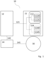
- FIG. 1 shows a system 10 for Current Perception Threshold (CPT) quantification of a user, the system configured to generate data for classifying patients with failed back surgery syndrome (FBSS) eligible for spinal cord stimulation (SCS) treatment according to one or more embodiments.
- the system comprises one or more electrode pairs 112, 114; a stimulator 12 configured to provide a plurality of electrical stimuli between the pair of electrodes 1120, 1125 and 1140, 1145 of each of the one or more electrode pairs 112, 114 respectively, wherein the plurality of electrical stimuli comprises a plurality of AC signals of a frequency from a predefined set of frequencies; a feedback element 16 configured to determine whether the electrical stimuli is felt by the user; and a processor 14, wherein the processor 14 is configured to control the stimulator 12 and receive an indication from the feedback element 16 whether the electrical stimuli is felt by the user.
- CPT Current Perception Threshold
- each electrode pair 112, 114 is composed of two electrodes 1120, 1125 and 1140, 1145 respectively, that allow an electrical current to flow from one to another. It is noted that the direction of this flow can be in either direction.
- the electrodes may be equally shaped while in other embodiments these electrodes may take different forms. For example, one electrode maybe be circular while the other may be ring-shaped, and the electrodes may be concentric. In some embodiments the electrodes may be placed one next to the other; while in other embodiments, the electrodes may be placed in different positions relative one to the other.
- the circular electrode may be placed inside the ring-shaped electrode, so that the current flow goes from the inner circular electrode to the outer ring-shaped electrode or from the outer ring-shaped electrode towards the inner circular electrode.
- the system 10 may comprise different electrode pair types. The possible disposition of the electrode pairs when the system comprises a plurality of electrode pairs will be further disclosed with reference to Figure 2 .
- the stimulator 12 is configured to provide a plurality of electrical stimuli to the electrodes through electrical means 121 such as wires.
- the electrical means 121 may comprise more than one wire comprising a plurality of conducting paths, wherein respective conducting paths are connected to respective electrodes of each electrode pair 112, 114.
- the stimulator 12 may be able to select one electrode pair 112, 114 from a plurality of electrode pairs. To do so, the stimulator 12 may comprise an electrical switch (not shown).
- the electrical switch may be internal or external to the stimulator 12 and the anode and cathode wires of each electrode pair 112, 114 may be common between the stimulator 12 and the electrical switch.
- the electrical means 121 may further comprise a control wire that allows the stimulator 12 to send control signals to the electrical switch to select the electrode pair the stimulus should be provided to.
- the stimulator 12 may comprise any suitable electrical controller for controlling which electrode pair an electrical stimulus is sent to.
- the stimulator 12 may comprise any suitable power source that powers it in AC or DC and the stimulator 12 may comprise a DC-AC inverter to convert DC current into the stimuli AC current.
- the stimulator 12 may comprise a pulse generator so that the stimuli can take different desired waveforms such as sinusoidal or squared waves.
- the stimulator 12 may be connectable to and powered by an external power source.
- the AC signals current may be therefore provided by an internal or an external power source.
- the plurality of electrical stimuli comprises a plurality of AC signals of a frequency from a predefined set of frequencies. These frequencies are determined taking into consideration the nerve fibres of interest to stimuli.
- the plurality of frequencies may comprise one or more of: a suitable frequency for preferentially stimulating the C-type fibres (for example 5Hz), a suitable frequency for preferentially stimulating the A ⁇ -type fibres (for example 250Hz) and a suitable frequency for preferentially activating the A ⁇ -type fibres (for example 2000Hz). It is noted that the plurality of frequencies may comprise other frequencies to stimulate other or the same nerve fibres in the same or different proportions.
- the intensity of the stimuli may be varied by varying the voltage amplitude or the current amplitude of the electrical stimuli (i.e.
- the stimulator 12 may be a variable current or voltage source). When the current amplitude is varied, the current amplitude may be comprised between greater than 0 and 10 mA.
- the stimulator 12 as a current source may have any suitable maximum output voltage, such as 180V.
- the term "preferentially” refers to any frequency which predominantly cause the referred fibre-type to be stimulated over other nerve-types (i.e. the majority of the electrical stimuli is converted into electric stimulation of the preferred fibre-type over the other fibre-types), even if the frequency also causes other fibre types to be stimulated.
- the objective of the apparatus is to obtain sensory thresholds for particular fibre-types. It is noted that the stimulation of one fibre-type or another does not depend exclusively on the frequency of the stimulus but on the duration of and electrical intensity of the stimulus, as well as the type of current and the waveform and the electrode shape and size.
- the predetermined set of frequencies comprises: a first frequency for preferentially stimulating C-type fibres, the first frequency preferably comprised between 2 and 6 Hz; and/or a second frequency for preferentially stimulating A ⁇ -type fibres, the second frequency preferably comprised between 200 and 300 Hz; and/or a third frequency for preferentially stimulating A ⁇ -type fibres, the third frequency preferably comprised between 1500 and 3000 Hz. It is noted that other frequencies may be used to stimulate each of the fibre nerves types depending on the particular setup used.
- the feedback element 16 is configured to determine whether the electrical stimuli is felt by the user.
- the feedback element 16 may be any suitable feedback element suitable for detecting whether the electrical stimuli is felt by the user.
- Active elements may comprise any interface the user may interact with such as: a touch screen or other display device with guided user interface (GUI); or a button or switch connected to a sensor configured to detect when the button or switch is pressed; a pressure sensor; a lever; a microphone and associated noise detection module (implemented in hardware and/or software) configured to detect a noise indicating that the stimulus is felt, optionally comprising a voice recognition software; a camera and associated image processing module (implemented in hardware and/or software) configured to detect any suitable visual indication from the user that the stimuli was felt; or any other suitable means .
- Passive elements may comprise any element capable of determining whether the electrical stimuli are felt by the user without any active input by the user.
- a pupil tracking device with an associated pupil tracking module (implemented in hardware and/or software) configured to detect a pupil dilation or contraction associated with the electrical stimulus being felt; a facial recognition device with an associated face tracking module (implemented in hardware and/or software) configured to detect a facial pose associated with the electrical stimulus being felt; as well as any other means that may be able to do so.
- the feedback element 16 is further connected to the processor 14 through the connection means 141, that may be either physical means such as a wire or a wireless connection such as a Bluetooth or Wi-Fi connection.
- the processor 14 may comprise one or more processing units, such as a microprocessor, GPU, CPU, multi-core processor or similar, and may be internal or external to the stimulator 12 or distributed between processors of different devices.
- the processor 14 is configured to control the stimulator 12 by indicating the activation of the stimulation and optionally controlling one or more characteristics of the stimuli such as the intensity, frequency, location, waveform or duration.
- the processor 14 is therefore connected to the stimulator 12 through the connection means 142 that may be either physical means such as a wire or a digital electromagnetic connection such as a Bluetooth or Wi-Fi protocols.
- the processor 14 is also configured to receive an indication from the feedback element 16 whether the electrical stimuli is felt by the user through the connection means 141.
- the system comprises a memory associated with the processor 14 configured to save all the information the processor 14 processes and obtain the saved information.
- the memory may comprise one or more volatile or non-volatile memory devices, such as DRAM, SRAM, flash memory, read-only memory, ferroelectric RAM, hard disk drives, floppy disks, magnetic tape, optical discs, or similar.
- the stimulator 12 may comprise a communication interface (not shown) configured to communicate with one or more external devices, and data obtained by the stimulator 12 may be sent to the one or more external devices, such as an external computer, server, mobile device or distributed computing system such as the cloud. It is noted that in some embodiments the processor 14 and optionally the memory, are comprised within the stimulator 12.
- the system 10 is further configured to trigger the electrical stimuli of the buttock, the lumbar, the thigh and/or the calf skin areas of the user through the one or more of electrode pairs, wherein each electrode pair defines a sub-area within the area. Therefore, the stimulator 12 provides stimuli to the body parts affected by the FBSS. Furthermore, the system 10 may be configured to trigger the electrical stimuli of a non-FBSS affected area, such as an upper limb, in order to calculate reference threshold values for the electrical stimuli as disclosed in further detail herein.
- the processor 14 is further configured to receive an indication of the location of the one or more electrode pairs 112, 114 on the buttock, the lumbar, the thigh and/or the calf, for a plurality of electrode pair positions (i.e. whether the one or more electrode pairs are placed on the buttock, lumbar thigh or calf, and optionally the sub-area within the area of the buttock, lumbar, thigh or calf on which each electrode pair is placed).
- This indication may be received from a user interface of an external device communicatively connected to the processor 14 (for example via an app of a mobile device or from a guided user interface GUI of an external device or a web portal), or may be provided via a user interface of a device comprising the processor 14.
- the processor 14 is further configured to, for each electrical stimulus, receive an indication by the feedback element whether the electrical stimuli was felt by the user, and for each frequency at each electrode pair position, determine a threshold value for the lowest electrical intensity felt by the user based on the received indications for each electrical stimulus, as described in further detail herein.
- the processor 14 is further configured to, for each frequency for the buttock, the lumbar, the thigh and/or the calf, calculate an average threshold value indicative of the lowest electrical intensity felt by the user, based at least in part on the threshold values determined, as described further herein.
- a practitioner may place the plurality of electrode pairs on the buttock, lumbar, thigh or calf in a predetermined position.
- the practitioner determines that the plurality of electrode pairs are correctly positioned, the practitioner provides the indication about where the plurality of electrode pairs are placed (e.g. by selecting the appropriate option on the user interface of "buttock”, “lumbar”, “thigh” or “calf", or by selecting an area on a schematic diagram of a patient body corresponding to the electrode pair position).
- the indication may include specific indications regarding the position of each of the plurality of electrode pairs within the area of the buttock, lumbar, thigh or calf.
- These specific indications may be provided manually by the practitioner or may be determined by the processor 14 according to pre-programmed instructions (i.e. in embodiments where the plurality of electrode pairs have a fixed spatial relation to one another, such as on a single substrate, such that, when the practitioner indicates that the substrate is correctly placed on the buttock, lumbar, thigh or calf, the processor 14 calculates the position of each electrode pair according to the pre-programmed instructions related to the fixed position of the electrode pairs on the substrate). Once the indication is received, the system 10 may provide the electrical stimuli and determine if they were felt by the user as described in further detail herein.
- the practitioner may then place the plurality of electrode pairs on another of the buttock, lumbar, thigh or calf and again provide an indication about where the electrode pairs are placed as before.
- the system 10 may again provide the electrical stimuli and determine if they were felt by the user. This may be repeated for two, three or all of the buttock, lumbar, thigh or calf or may only be performed for one of the buttock, lumbar, thigh or calf.
- the same process may be performed for one or more electrode pair positions placed on a non-FBSS-affected area, such as an upper limb, to generate a set of reference threshold values for a non-FBSS-affected area.
- a practitioner may place the electrode pair on the buttock, lumbar, thigh or calf in a predetermined position. Once the practitioner determines that the electrode pair is correctly positioned, the practitioner provides the indication about where the electrode pair is placed (e.g. by selecting the appropriate option on the user interface of "buttock”, “lumbar”, “thigh” or “calf", or by selecting an area on a schematic diagram of a patient body corresponding to the electrode pair position). The indication may also include a specific indication regarding the position of the electrode pair within the area of the buttock, lumbar, thigh or calf.
- This specific indication may be provided manually by the practitioner or may be determined by the processor 14 according to pre-programmed instructions (i.e. the practitioner places the electrode pair in a specific position within the area of the buttock, lumbar, thigh or calf and confirms that it is placed in the area corresponding to the area saved in the pre-programmed instructions).
- the system 10 may provide the electrical stimuli and determine if they were felt by the user as described in further detail herein.
- the practitioner may then place the electrode pair on another area within the buttock, lumbar, thigh or calf, and again provide an indication about where the electrode pair is placed as before.
- the system 10 may again provide the electrical stimuli and determine if they were felt by the user.
- the practitioner may place the electrode pair on another of the buttock, lumbar, thigh or calf and again provide an indication about where the electrode pairs are placed as before.
- the system 10 may again provide the electrical stimuli and determine if they were felt by the user. This may be repeated for two, three or all of the buttock, lumbar, thigh or calf or may only be performed for one of the buttock, lumbar, thigh or calf.
- the same process may be performed for one or more electrode pair positions placed on a non-FBSS-affected area, such as an upper limb, to generate a set of reference threshold values for a non-FBSS-affected area.
- the practitioner is able to place the electrode pairs at plurality of electrode positions within each of one or more of the buttock, lumbar, thigh and calf.
- the plurality of electrode pair positions may be provided simultaneously in the case where the system 10 comprises a plurality of electrode pairs (i.e. each electrode pair corresponds to an electrode pair position), or a single electrode pair may be place consecutively in a plurality of electrode pair positions (i.e. the single electrode pair is placed in a plurality of electrode positions).
- the system 10 is configured provide multiple electrical stimuli at each electrode pair position and determined if each of the electrical stimuli were felt by the user, according to the methods disclosed herein.
- the practitioner may place the one pair or plurality of electrode pairs on a non-FBSS-affected area in one or more predetermined electrode pair positions on the non-FBSS-affected area.
- the plurality of electrode pair positions may be provided simultaneously in the case where the system 10 comprises a plurality of electrode pairs (i.e. each electrode pair corresponds to an electrode pair position), or a single electrode pair may be place consecutively in a plurality of electrode pair positions (i.e. the single electrode pair is places in a plurality of electrode positions).
- the practitioner determines that the one pair or plurality of electrode pairs are correctly positioned, the practitioner provides the indication about where the plurality of electrode pairs are placed, i.e. the practitioner may indicate that the plurality of electrode pairs are positioned in the predetermined position of the non-FBSS-affected area. Then the system 10 is configured to provide multiple electrical stimuli at each electrode pair position and determined if each of the electrical stimuli were felt by the user, according to the methods disclosed herein. The determination of the thresholds in a non-FBSS-affected area may be then used a reference as described in further detail herein.
- the data obtained through the system 10 can be correlated to the mental condition of the user and therefore does not only provide a CPT quantification, but it also provides data that can provide useful information regarding the mental condition of the user.
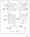
- Figure 2 shows a plurality of sets of electrode pairs of system 10 according to one or more embodiments.
- the one or more electrode pairs 110 are provided on a substrate 115 for placing the electrode pairs to the skin of the user.
- the substrate 115 of the different electrode pair sets configure the electrodes to be spatially located in different locations relative to each other, allowing for a desired distribution according to the area of the body the set of electrode pairs are configured to be placed.
- the substrate 115 may distribute the electrode pairs 110 in such way that they cover most of the buttock, the lumbar, the thigh and/or the calf skin areas of the user with the electrode pairs distributed about the area of the body.
- the substrate 115 may distribute the electrode pairs 110 by considering the nerve distribution of a non-FBSS-affected skin area, such as the upper limb. It is noted that each electrode pair 110 comprises two electrodes and that each electrode may take different shapes and sizes and dispositions relative to each other as previously mentioned.
- the substrate may help fixing the electrodes in the desired place and may include an adhesive surface or any affixing element.
- the substrate is configured to be detachable from the electrode pairs, so that in use it can be used as a template or stencil for the electrodes but not applied or fixed to the user.
- the set of electrode pairs 200A comprises an array of three rows of evenly distributed electrode pairs, preferably in a 4-3-4 formation.
- the set 200A is particularly adapted to stimulate the fibres in variety of sub-areas of the lumbar.
- the set of electrode pairs 200B comprises an array of three rows of evenly distributed electrode pairs, preferably in a 3-3-3 formation forming a rhombus shape.
- the set 200B is particularly adapted to stimulate the fibres in variety of sub-areas of the buttock.
- the set of electrode pairs 200C comprises an array of four rows of evenly distributed electrode pairs, preferably in a 3-3-3-3 formation forming a rectangular shape.
- the set 200C is particularly adapted to stimulate the fibres in variety of sub-areas of the thigh.
- the set of electrode pairs 200D comprises an array of four rows of electrode pairs, preferably in a 3-2-2-1 formation.
- the set 200D is particularly adapted to stimulate the fibres in variety of sub-areas of the calf.
- the set of electrode pairs 200E comprises an array of three electrode pairs.
- the set 200E is particularly adapted to stimulate the fibres on the upper arm (e.g. in the biceps or triceps area), the lower arm (e.g. the ulna or radii area) and the hand.
- the system 10 may comprises a plurality of sets of electrode pairs having different formations adapted to stimulate a plurality of the lumbar, buttock, thigh, calf and non-FBSS-affected area such as an upper limb.
- the plurality of sets of electrode pairs may be removably connectable to the stimulator 12 by electrical connectors, so that the practitioner is able to connect the appropriate set of electrodes for stimulating a particular area of the body.
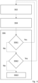
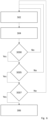
- FIG 3 shows a diagram of several processing steps the processor 14 of the system 10 is configured to perform, according to one or more embodiments.
- the processor 14 is configured to take the step 302 wherein, for each frequency of a set of predefined frequencies for each of a plurality of electrode pair positions, an indication of the location of the electrode pair positions on the buttock, the lumbar, the thigh and/or the calf is received, the stimulator 12 is controlled to provide two or more electrical stimuli at each frequency for each electrode pair position, the two or more electrical stimuli having different electrical intensities (e.g. voltage or current amplitude intensities).
- the stimulator 12 is controlled to provide two or more electrical stimuli at each frequency for each electrode pair position, the two or more electrical stimuli having different electrical intensities (e.g. voltage or current amplitude intensities).
- the stimulator 12 may be configured to provide a plurality of stimuli having the same intensity and frequency (for example a plurality of stimuli at a frequency F1 and intensity 11, and a plurality of stimuli at frequency F1 and intensity 12).
- the indication of the location of the electrode pair positions may be provided through electronic means from a user interface located in a separate device.
- the user interface may comprise buttons, knobs, sliders, levers, wheels, a touchscreen, and so on, that the user can use to indicate the location of the electrode pair positions.
- a plurality of predetermined electrode pair positions may be saved in a memory of the system 10 and the indication may be a selection of the relevant predetermined electrode pair positions which corresponds to the electrode pair position on the patient.
- the indication may simply be a confirmation indication made via a user interface that the electrode pair position is a predetermined electrode pair position saved in the memory.
- the system 10 comprises the user interface either as a separate element or comprises within any of the other elements of the system.
- the stimulator 12 is controlled through the means 142 and the processor 14 may indicate the location of the electrode pair position to stimulate and the frequency, time and/or intensity of the stimuli to be applied.
- the processor 14 is also configured to take the step 304, wherein for each electrical stimulus, an indication is received by the feedback element 16 whether the electrical stimuli was felt by the user.
- the processor 14 may receive the indication through the means 141. It is noted that in some embodiments the feedback element 16 may provide feedback only when the electrical stimuli was felt by the user, while in other embodiments the feedback element 16 may provide a positive feedback when the electrical stimuli was felt by the user, and a negative feedback when the electrical stimuli was not felt by the user, or feedback element 16 may provide feedback only when the electrical stimuli was not felt by the user.
- the processor 14 is further configured to take the step 306, wherein for each frequency at each electrode pair position, a threshold value is determined for the lowest electrical intensity felt by the user based on the received indications for each electrical stimulus. This threshold value may be determined by configuring the processor 14 to process the information regarding the stimuli provided, including its frequency and intensity, and the indication whether the electrical stimuli was felt by the user. In some embodiments the processor 14 is further configured to determine, for each frequency at each electrode pair position the threshold value of step 306 is determined by selecting the lowest electrical intensity indicated as being felt by the user.
- the threshold value of step 306 is determined by further analysing the lowest electrical intensity indicated as being felt by the user. In some embodiments, the threshold value of step 306 is determined by selecting the lowest electrical intensity indicated as being felt by the user wherein the immediately higher electrical intensity is also indicated as being felt by the user.
- the threshold value of step 306 is determined by selecting the lowest electrical intensity indicated as being felt by the user wherein the threshold value for the lowest electrical intensity is indicated as felt by the user at least twice; or by selecting the lowest electrical intensity indicated as being felt by the user wherein the threshold value for the lowest electrical intensity is indicated as felt by the user more than half of the times; or by selecting the lowest electrical intensity indicated as being felt by the user wherein the threshold value for the lowest electrical intensity is indicated as felt by the user all the times.
- a further embodiment of step 306 will be detailed with reference to Figure 4 .
- the processor 14 is further configured to perform step 308, wherein for each frequency for the buttock, the lumbar, the thigh and/or the calf, an average threshold value is calculated for the lowest electrical intensity felt by the user, from at least the threshold values determined in the step 306.
- the calculated average threshold values may be non-standardised, i.e. they are not standardised in relation to threshold values obtained in a non-FBSS-affected area, or they may be standardised averages obtained in relation to threshold values obtained in a non-FBSS-affected area. In some embodiments, both non-standardised and standardised average threshold values are obtained.
- the average threshold value may be computed by obtaining the arithmetic mean of the threshold values from the electrode pair positions for the buttock, the lumbar, the thigh and/or the calf.
- the processor 14 is configured to take the step 301 of determining a reference range of electrical intensity. This step will be further described with reference to Figure 5 .
- the processor 14 is further configured to obtain a standardised average threshold value with respect to a non-FBSS-affected electrode position; wherein the standardised average threshold value is indicative of the difference between a threshold value and the non-FBSS threshold value.
- the processor 14 is therefore configured to take the steps of: a) for each frequency of the set frequencies for a non-FBSS-affected electrode pair position to activate the stimulator 14 providing two or more electrical stimuli at the frequency and non-FBSS-affected electrode pair position, the two or more electrical stimuli having different electrical intensities; b) for each electrical stimulus at the non-FBSS-affected electrode pair position, determining by the feedback element 16 whether the electrical stimuli was felt by the user; c) for each frequency at the non-FBSS-affected electrode pair position, determining a non-FBSS threshold value for the lowest electrical intensity felt by the user based on the received indications for each electrical stimulus; and d) calculate a standardised threshold value indicative of the difference between an average threshold value in an FBSS-affected area
- the standardised average threshold value may for example be a subtraction of the non-FBSS threshold value from the FBSS threshold value, or a ratio may be calculated. It is noted that in the embodiments wherein electrode pairs are configured to be placed on a non-FBSS-affected area in a predetermined position all the previous consideration regarding the activation of the stimulator 12 (step 302), the determination whether the stimuli was felt by the user by the feedback (step 304) the threshold value determination (step 306) and the average threshold value calculation (step 308) are equivalently applicable to these steps the processor 14 is configured to take.
- non-FBSS-affected electrode pair position and "non-FBSS-affected area” are referred to a position/area over the skin surface over a place where FBSS related pain is not located. This may comprise, for example, the upper limb or the shoulder.
- this standardised average threshold may be reliable source of information to classify patient with failed back surgery syndrome (FBSS) eligible for spinal cord stimulation (SCS) treatment taking into account the mental condition of the patient.
- FBSS failed back surgery syndrome
- SCS spinal cord stimulation
- the processor 14 is further configured to generate a set of data from the determined CPT wherein the data indicates one or more of the following: the threshold value as a function of stimuli frequency for the plurality of electrode pair positions; and one or more maps of the threshold value as a function of electrode pair position, each map indicating the threshold value for a single frequency. Therefore, the threshold values may be grouped by frequencies, or by location and may be filtered to provide information reading only a location, frequency or intensity of interest. This may help the practitioner to analyse the data in different way and determine the classification of the patient.
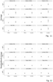
- the system 10 further comprises a display device configured to display the set of data, wherein the processor 14 is further configured to display the set of data on the display device, as shown in Figures 13A and 13B.
- Fig. 13A shows the calculated threshold values in mA for each electrode pair position (locations 1-4), wherein the threshold for each electrode pair position is indicated by a unique colour with markers at the threshold value for each frequency and connecting lines between the markers.
- Fig. 13B shows the calculated threshold values in mA for particular frequencies, illustrated on a graphic of the electrode pair positions.
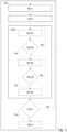
- Figure 4 shows a diagram showing further steps the processor 14 is configured to take in order to improve the system's 10 reliability when abnormal inputs are received, according to one or more embodiments.
- the processor 14 may be configured to perform the step 3061 of checking if, for all the intensities provided to the user in a particular electrode pair position and frequency, the indication received by the feedback element 16 whether all the electrical stimuli were felt by the user is positive, i.e. indicates the user has felt it all of the stimuli, the processor 14 is configured to repeat the steps 302 and 304 for that electrode pair location and frequency with a lower set of intensities.
- the processor 14 is further configured to perform the step 3062 of checking if for all the intensities provided to the user the indication received by the feedback element 16 whether none of the electrical stimuli were felt by the user is negative, i.e. indicates the user has not felt any of the stimuli, the processor 14 is configured to repeat the steps 302 and 304 for that electrode pair location and frequency with a higher set of intensities. If that is not the case, the processor 14 is then configured to take the step 3063, wherein it determines a threshold value for the lowest electrical intensity felt by the user based on the received indications for each electrical stimulus as previously described in step 306.
- steps 3061 and 3062 may be interchangeable and therefore the processor 14 may be configured to first check if none of the stimuli were felt by the user and then check if all the stimuli were felt by the user, through the feedback element 16. Steps 3061 and 3062 may instead be comprised in a single step checking whether both positive and negative indications were received, and if so proceeding to step 3063, if not repeating steps 302 and 304 with a higher and/or lower set of intensities. It is also noted that in some embodiments, the processor 14 may not be configured to take the steps 3061 or 3062.
- Figure 5 shows a diagram of a previous step 301 the processor 14 is further configured to make in order to determine a reference range of electrical intensity according to one or more embodiments.
- the processor 14 may be configured to take the step 3011 of receiving an indication of the location of an electrode pair position and controlling the stimulator 12 to provide one or more preliminary stimuli to the user at the electrode pair position. In some embodiments, this may be done for one or more frequencies from a predetermined set of frequencies and for a reference electrode pair position on the buttock, the lumbar, the thigh and/or the calf. It is noted that in some embodiments the reference electrode pair is predetermined while in other embodiments the reference electrode pair is randomly chosen from the electrode pairs available.
- the processor 14 may be then configured to take the step 3012 of receiving one or more indications via the feedback element 16 whether the electrical stimuli were felt by the user.
- the processor may be then configured to take step 3013, of determining a reference range of electrical intensity based in the received indications. In some embodiments, this is done for each frequency at the reference electrode pair position whilst in others the same reference range is used for all frequencies. It is noted that for the embodiments wherein electrode pairs have been also placed on a non-FBSS-affected area in a predetermined position, the processor may be configured to take the steps as described above.
- the reference range of electrical intensity may be then determined according to one or more embodiments as follows.
- the processor 14 may be configured to take step 30132, wherein a first plurality of stimuli sequentially ascending in electrical intensity is provided.
- the processor 14 may be then configured to take step 30136, wherein a second plurality of stimuli sequentially descending in electrical intensity is provided.
- the processor 14 may be then configured to take the step 30139, wherein the maximum and minimum for the reference range are selected to be the highest and lowest electrical intensities wherein a change in the received indications is noted.
- the processor 14 is further configured to take step 30134, wherein if none of the indication via the feedback element 16 whether the electrical stimuli were detected, the step 30132 is repeated with higher intensities. In some embodiments, the processor 14 is further configured to take step 30138, wherein if all of the indication via the feedback element 16 whether the electrical stimuli were detected, the step 30136 is repeated with lower intensities. In some embodiments, the processor 14 is further configured to take step 3014, wherein if the reference range of electrical intensity is higher than a predetermined maximum range the steps 3011, 3012 and 3013 are repeated until the reference range is less than the predetermined maximum range, unless a maximum number of iterations is reached.
- the processor 14 may be configured to repeat steps 3014 if the reference range of electrical intensity is higher than 0.5mA until the reference range is less than 0.5 mA, unless a maximum number of iterations, such as 3, is reached, wherein the processor is configures to take the step 3015 of considering such range as the reference range of electrical intensity.
- the system 10 further comprises a memory and the processor 14 is configured to store, for each of the electrical stimuli, data indicating one or more of the following: 1) the intensity, frequency, electrode pair position, the location of the electrode pair position on the buttock, the lumbar, the thigh and/or the calf of step 302; 2) whether the electrical stimulus has been felt by the user in step 304; 3) the threshold value of step 306; and 4) the average threshold value of 308.
- the memory is therefore configured to store the information provided by the processor 14 related to the steps 302, 304, 306 and 308, and to provide such information to the processor 14 when required by the processor 14.
- the processor may be configured to store one or more of the following: the location of the electrode pair position of the non-FBSS-affected area; whether the electrical stimulus has been felt by the user; the threshold value; and the standardised average threshold value.
- Figure 6 shows a diagram of a step 305 the processor 14 is further configured to, before taking the step 306, check if all the electrode pair positions of the plurality of pair positions and if all the frequencies of the plurality of frequencies the steps 302 and 304 have been applied, according to one or more embodiments.
- step 3000 it is determined whether the processor 14 has performed the steps 302, 304 in all the electrode pairs positions. If not the processor 14 is configured to take the steps 302, 304 again with another electrode pair position.
- the processor proceeds to step 3005.
- step 3005 the processor 14 determines whether steps 302, 304 have been performed for all the frequencies.
- step 3005 it is determined that steps 302, 304 have been performed for all the frequencies
- the processor proceeds to step 3007.
- step 3007 the processor 14 determines whether steps 302, 304 have been performed for all predetermined electrical intensities. If not the processor 14 is configured to take the steps 302, 304 again with another frequency. When at step 3007 it is determined that steps 302, 304 have been performed for all the intensities, the processor proceeds to step 306. In some embodiments, the steps 3000, 3005, or 3007 may not be performed.
- the processor 14 may be configured to take steps 3000, 3005, and/or 3007 in a specific order, for example first step 3000, then 3005 and then 3007 while in other embodiments the order may be first step 3007 then 3000 and then 3005 or maybe first step 3007 then 3005 and then 3000. It is also noted that the processor 14 may be configured to take steps 3000, 3005 and /or 3007 before steps 3004, 3008 or before any other step. Therefore, the processor 14 would be configured to take the previous steps again with the new electrode pair position and/or location.
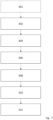
- Figure 7 shows a diagram of the steps the processor 14 may be configured to take according to one or more embodiments, wherein the system 10 is configured to prognosticate the outcome of a patient with failed back surgery syndrome (FBSS) undergoing a spinal cord stimulation (SCS) treatment. Therefore, the system is configured to take the steps 302, 306, and 308 as previously described and optionally is configured to take the step 301 as previously described.
- the processor 14 is further configured to take step 3010, wherein the one or more average threshold values are compared with one or more predetermined standard average threshold values. Then the processor 14 is configured to take step 312, wherein the outcome of the patient undergoing an SCS treatment from the significant deviations found in the comparison is determined.
- the patients with an excellent response to SCS have significant higher averages CPTs compared to the rest, in the lumbar and the buttock regions at 5Hz, 250Hz and 2kHz.
- the processor 14 may be configured to compare either one or more average threshold values or one or more standardized average threshold values.
- the standardized average threshold values may be obtained from computing the difference between one or more average threshold value and a non-FBSS threshold value.
- the system 10 may be configured to prognosticate the mental health outcome of a patient with failed back surgery syndrome (FBSS) as a result of spinal cord stimulation (SCS) treatment.
- FBSS failed back surgery syndrome
- SCS spinal cord stimulation
- a second aspect of the invention refers to a computer-implemented method according to one or more embodiments to generate data for classifying patients with failed back surgery syndrome (FBSS) eligible for spinal cord stimulation (SCS) treatment, wherein the method comprises the following steps:
- the received data from step a) could be obtained using a device according to any of the embodiments disclosed herein.
- the method further comprises the step of:
- non-FBSS threshold value for the lowest electrical intensity felt by the user in a non-FBSS-affected area may be received through the steps a) to c) from non-FBSS-affected area, i.e. by
- the computer-implemented method may be performed on any suitable computing system comprising one or more processing units, such as a microprocessor, GPU, CPU, multi-core processor or similar, a server or a distributed computing system such as the cloud.
- processing units such as a microprocessor, GPU, CPU, multi-core processor or similar, a server or a distributed computing system such as the cloud.
- standardise in the present invention may be understood as adjusting different values by comparing them to a norm or a standard value, so that the standardised values are indicative of the amount of deviation from the norm. This comparison may comprise normalising using the standard value as the mean or calculating the difference to the standard value, either absolute or relative.
- the standardisation may be performed by subtracting the non-FBSS average threshold value from the average threshold values of the FBSS-affected areas (buttock, lumbar, thigh and/or calf), or a ratio of the calculated threshold values of the FBSS-affected areas to the non-FBSS average threshold value may be calculated.
- this standardised average threshold value may be a reliable source of information to classify patient with failed back surgery syndrome (FBSS) eligible for spinal cord stimulation (SCS) treatment.
- FBSS failed back surgery syndrome
- SCS spinal cord stimulation
- a non-FFBS-affected area can be any area where the FFBS neuropathic effects are not present, such as, for example, the superior limb.
- the average threshold value for the lowest electrical intensity sensitive to the user of a non-FFBS-affected area may be obtained using the same methods described herein for the average threshold value for the lowest electrical intensity felt by the user for the FFBS-affected areas, i.e. the buttock, the lumbar, the thigh and/or the calf; by taking the steps a) to c) with regard to the non-FFBS-affected area. It is further noted that therefore the data needed for obtaining the average threshold value of a non-FFBS-affected area could be obtained using a device according to any of the embodiments disclosed herein.
- the method further comprises the step of: f) generating data for classifying patients with FBSS eligible for SCS treatment from the determined CPT wherein the data indicates one or more of the following:
- the data generated may help to enhance the reading and interpretation of the data when displayed to a user.
- the threshold value of different electrode pair locations can be compared across different locations for a selection of frequencies or the threshold value of different electrode pair locations can be spatially displayed to enhance the spatial analysis of such threshold values.
- Another computer-implemented method relates to a computer-implemented method to prognosticate the outcome of a patient with failed back surgery syndrome (FBSS) undergoing a spinal cord stimulation (SCS) treatment, wherein the method comprises the steps of any of the previous methods and further comprises the steps:
- FBSS failed back surgery syndrome
- SCS spinal cord stimulation
- the standard values for the data may be obtained from the comparison of the threshold values for patients wherein the SCS treatment has been successful versus those whose SCE treatment was not successful, for a particular apparatus setup. Therefore, the standard values may be, for example, a threshold value that may serve as a reference to find a deviation with, in step h) (e.g. if the calculated threshold value is above the standard value then it is determined that there is a significant deviation).
- a third aspect of the invention refers to computer program product comprising instructions which, when the program is executed by a processor, cause the computer to carry out the steps of any of the methods according to the second aspect of the invention.
- the computer program product may be implemented on hardware and/or software.
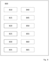
- Figure 8 shows a computer program product 800 to implement the methods disclosed in the present document, that may be implemented in software, hardware or a combination thereof.
- the module may be saved in a memory of the system (for example, in the stimulator or the user interface), or may be saved remotely, for example, in a remote server or distributed computing system communicatively connected to the system.
- the computer program product 800 is communicatively connected to the electronic components of the system.
- the computer program product 800 may be configured to perform any of the steps of the method described with reference to Figures 3-7 .
- the module may comprise an electrode pair selecting module 810 configured to select the electrode pair from a plurality of electrode pairs.
- the electrode pair selecting module 810 is also configured to select the reference electrode pair to perform the steps to determine the reference range of electrical intensity.
- the electrode pair selecting module 810 is configured to select one of the electrodes for determining the reference rage (for example randomly).
- the electrode pair selecting module 810 is configured to select an electrode pair for each electrical stimulus to be provided by the system 10.
- the electrode pair selecting module 810 may be configured to ensure all the electrode pair positions have been provided with the multiple stimuli according to the method.
- the electrode pair selecting module 810 may therefore control an electrical switch or other electronic controller comprised in the stimulator or external to the stimulator to control which electrode pair each stimulus is sent.
- the electrode pair selecting module 810 may be configured to receive a manual selection or deselection from the user via a user interface, so that the module 810 will ensure that electrical stimuli according to the method are or are not sent to the selected/deselected electrode pair indicated by the user via the user interface.
- the module 800 may select the electrode pairs according to a predetermined sequence saved in the memory. In the embodiments wherein the electrode pair selecting module 810 is not comprised in the module 800, a predetermined set of selected set of electrode pairs, may be used. In embodiments where the system 10 only comprises one electrode pair, the module 810 is not provided.
- the module may comprise a frequency selecting module 815 configured to select the frequency from a plurality of frequencies.
- the frequency selecting module 815 is configured to select the frequency from a plurality of frequencies for the reference stimuli when a reference range of electrical intensity is being determined.
- the frequency selecting module 815 is configured to select the frequency of each stimuli and control the stimulator 12 to provide the stimuli at the selected frequency.
- the frequency selecting module 815 may be configured to determine whether stimuli over all the frequencies have been provided according to the methods disclosed herein.
- the frequency selecting module 815 may be configured to receive a manual selection or deselection of frequencies from the user via a user interface, so that the module 815 will ensure stimuli are/are not provided at the frequencies selected/deselected by the user via the user interface.
- a predetermined set of selected frequencies may be used. In some embodiments only a single frequency may be used, in which case the module 815 may not be provided.
- the module 800 further comprises an intensity selecting module 830 configured to select the intensity of the stimuli.
- the intensity selecting module 830 is configured to select the intensity of the stimuli applied when a threshold value is being determined.
- the intensity module is connected to the stimulator of the system to control the intensity to be provided.
- the intensity selecting module 830 is configured to ensure all the intensities from a plurality of intensities are being provided.
- the intensity selecting module 830 may be configured to receive the plurality of intensities from a user via a user interface.
- the intensity selecting module 830 is configured to select the intensity from a plurality of frequencies in the embodiments wherein a reference range of electrical intensity is being determined. It may be therefore configured to apply the intensities sequentially ascending and/or sequentially descending to find the reference range of electrical intensity. It may be configured to repeat a set of intensities from the plurality of intensities if the reference range of electrical intensity is too big unless it is within a desired range or a predetermined maximum number of iterations are performed.
- the module comprises a stimulating module 820 configured to control, for the electrode pairs selected by the electrode pair selecting module 810,, the stimulator 12 to provide the stimuli with the frequencies selected by the frequency selecting module 815 and the intensity selected by the intensity selecting module 830 according to the invention.
- the stimulating module 820 is configured to provide control signals to the stimulator 12 to provide the electrical stimuli for determining the reference range.
- the module further comprises an indication module 825 configured to determine if each stimulus has been felt by the user.
- the indication module 825 is connected to the feedback element of the system. The output of the feedback element indicates whether the stimulus has been felt.
- the indication module 825 is configured to determine if one or more stimulus have been felt by the user considering the output of the feedback element. For example, if the feedback element only provides indication if the user has felt the stimulus, the indication module 825 may determine the lack of output from the feedback element when a stimulus is provided as an indication of the stimulus not being felt, and an output coincident with a stimulus as an indication of the stimulus being felt.
- the indication module 825 determines that none of the stimuli were felt for a given frequency, the indication module 825 instructs stimulating module 820 to provide further stimuli of higher intensities. If the indication module determines that all the stimuli were felt, the indication module 825 instructs the stimulating module 820 to provide further stimuli of lower intensities
- the stimulating module 820 is configured to interact with the indication module 825 to see if none or all stimuli were felt and if so, provides further stimuli. If the indication module 825 indicates that none of the stimuli were felt, the further stimuli are provided with higher intensities, while if all the stimuli were felt, the further stimuli are provided with lower intensities.
- the module further comprises a threshold module 835, configured to determine, for the electrode pairs selected and the frequencies selected, the threshold based on the information provided by the indicating module 825 and the intensity selecting module 830. Given a set of intensities selected by the intensity selecting module 830 for a given electrode pair and frequency, the threshold module 835 will select as the threshold value the lowest electrical intensity the indication module 825 has determined as felt by the user. It is noted that any other criteria to select a threshold value may be used. For example, it may be selected as the threshold value the lowest intensity wherein at least the immediately higher intensity selected by the intensity selecting module 830 has been also determined by the indication module 825 as felt by the user.
- the threshold module 835 may require that an intensity has been determined by the indication module 825 as felt by the user at least twice or more than half of the times before being selected as the threshold value. The threshold module would be then configured to avoid false positive or phantom sensations from the user.
- the module may comprise an intensity range determination module 840, configured to determine a range of intensities from the information provided by the indication module 825 and the intensity selecting module 830 in the embodiments wherein a reference range is determined. If for an intensity selected by the intensity selecting module 830, the indication module 825 indicates the user has felt the stimuli, such stimulus is tagged as felt, and vice versa. Given a set of stimuli tagged, the intensity range determination module 840 can determine the intensity at which a change in the information provided by the indication module is noted. Such change may be determined as a limit (either upper or lower) of the range of electrical intensity. The intensity range determination module 840 may be configured to indicate the intensity selecting module 830 the range within the intensities may be selected from. In the embodiments wherein the intensity range determination module 840 is not comprised in the module 800, a predetermined set of intensities may be used.
- the module may comprise a standardisation module 845 configured to compare the average threshold value of the buttock, the lumbar, the thigh and/or the calf with the average threshold value of a non-FBSS-affected area of the body, like the upper limb.
- the standardisation module 845 is configured to compute a standardised value indicative of the difference between the average threshold value of the buttock, lumbar, thigh and/or calf and the threshold value of a non-FBSS-affected area of the body.
- the module 845 may in some embodiments calculate the ratio of the average threshold value the buttock, the lumbar, the thigh and/or the calf with respect to the average threshold value of a non-FBSS-affected area of the body, obtaining a standardised average threshold value of the buttock, the lumbar, the thigh and/or the calf.
- the module may comprise a data storage module 850, configured to store the information provided by the electrode pair selecting module 810, the frequency selecting module 815, the indication module 825, intensity selecting module 830, the threshold module 835, the intensity range determination module 840 and/or the standardisation module 845.
- the data storage module 850 may be configured to take information from these modules and save it to the memory, and optionally to further retrieve information from the memory and provide it back to these modules. Therefore, the data storage module 850 may be configured to store in the memory the electrode pair location selected from the electrode pair selecting module 810, the frequency from the frequency selecting module 815 and/or the intensity from the intensity selecting module 830, regarding the stimuli provided to the user.
- the data storage module 850 may be further configured to store in the memory the indications whether the stimuli was felt but the user from the indication module 825.
- the data storage module 850 may be further configured to store in the memory the average threshold value determined by the threshold module 835.
- the data storage module 850 may be further configured to store in the memory the intensity ranges indicated by the intensity range determination module 840.
- the data storage module 850 may be further configured to store in the memory the standardised average threshold value determined by the standardisation module 845. It is noted that the data storage module may store any other information in the memory.
- the a data storage module 850 may save the related information from a predetermined set of selected set of electrode pairs, frequencies and/or intensities.
- the module comprises a comparison module 855 configured to compare an average threshold value with a predetermined standard average threshold value.
- the comparison module 855 may receive information from the data storage module comprising the average threshold value and/or the standardised average threshold value. Then the information of the comparison will be provided to the outcome module 860. It is noted that the comparison may be stored in the memory by the data storage module 850.
- the module comprises an outcome module 860, configured to determine an outcome base on the comparison information provided by the comparison module 855.
- the outcome might comprise the response of the patient to the SCS treatment, a certainty level of such response as well as any other information that could help take a decision on the SCS treatment, like information regarding the mental health condition of the user. It is noted that the outcome may be stored in the memory by the data storage module 850.
- the module comprises a display module 865, configured to display the data generated by the processor, Therefore, the display module 865 may be configured to display in the display device the electrode pair location selected from the electrode pair selecting module 810, the frequency from the frequency selecting module 815 and/or the intensity from the intensity selecting module 830, regarding the stimuli provided to the user.
- the display module 865 may be further configured to display in the display device the indications whether the stimuli was felt but the user from the indication module 825.
- the display module 865 may be further configured to display in the display device the average threshold value determined by the threshold module 835.
- the display module 865 may be further configured to display in the display device the intensity range indicated from the intensity range determination module 840.
- the display module 865 may be further configured to display in the display device the standardised average threshold value determined by the standardisation module 845.
- the display module 865 may be configured to display in the display device the comparison from the comparison module 855.
- the display module 865 may be configured to display in the display device the outcome from the outcome module 860.
- the display module 865 may be further configured to display in the display device any of the previous information from the data storage module 850. It is noted that the display module 865 may display the information in preferred ways to enhance the reading and interpretation of the data displayed.
- the data may be displayed in the display device in form of a lookup table.
- the threshold value and/or the average threshold value may be displayed as a function of stimuli frequency for the plurality of electrode pair positions.
- one or more maps of the threshold value as a function of electrode pair position may be displayed, each map indicating the threshold value for a single frequency.
- CPT current perception thresholds
- Inclusion criteria were patients older than 18 years, diagnosed with FBSS who presented symptoms of low back pain and/or pain of neuropathic origin in the lower limbs, that were refractory to conservative analgesic treatments, with more than three months of evolution, presented pain intensity, measured with the Visual Analogical Scale (VAS), greater or equal than 5, not candidate for new spinal surgery and had an adequate understanding of the risks and benefits of treatment with SCS.
- Exclusion criteria were previous spinal interventions with a time of evolution of less than 6 months, vertebral instability with risk of progression, pregnancy, carriers of pacemaker and/or defibrillator (contraindication to use the EQSA system), the presence of tumours in the area of application of the EQSA system or allergies to the electrodes of the EQSA.
- the Exclusion criteria were: 1. Present behavioural disorders related to opioid use that suggest abuse or playful use of opioids (e.g., escalating doses without a prescription, loss of prescriptions, loss of opioid medications, obtaining opioids from multiple prescribers); 2. Present psychological or psychiatric comorbidities that contraindicate the implant (e.g., untreated high mood disorders, untreated psychosis, severe personality disorders); 3.Present coagulopathies, immunosuppression, local or systemic infections; 4.Present any associated pathology that conditions an unacceptable surgical risk; 5.The inability of the patient to understand the technique and/or use of neurostimulation.
- the SCS trial was finally performed in 15 patients in the SC group. In other three SC group patients, the SCS trial was delayed because the presence of intercurrent disease in one case, and by choice of the patients in the other two
- the SCS trial phase lasted 8 days.
- the therapy consisted of implanting two octopolar cylindrical electrodes percutaneously (Vectris SureScan, Minneapolis, MN) in the posterior epidural space at thoracic level (Day 0). Access was made with fluoroscopy support, at paraspinal level and the T12-L1 or L1-L2 vertebral segments were selected, depending on the patient's anatomy. The final location of the electrode was determined intraoperatively, after achieving that the paraesthesia caused by the neurostimulation covered all the painful areas referred by the patient. The distal end of the electrode must be placed over the T8/T9 segments. Once implanted, during the entire test phase, the electrodes were connected to an external neurostimulator.
- LD Low-dose stimulation
- HD High-dose stimulation
- Patients received the first stimulation with HD for 4 days (Day 1 to 4), after which they will start the stimulation with the LD alternative pattern, for another 4 days (Day 5 to 8). On the 5th day, whether or not the patient has responded positively to the initial therapy, the change in the stimulation programming was made to initiate the alternative pattern.
- the definitive evaluation of the analgesic benefit obtained with SCS was made. If the analgesic benefit, measured by the VAS and the percentage of global improvement at the back and/or leg, was equal or superior to 50% of the basal pain, it was considered as "responsive” and the internal pulse generator (IPG) was implanted to complete the system implantation. If the benefit was less, the patient was considered “non-responsive" to SCS therapy, and the electrodes were explanted.
- the implantation of the IPG (Intellis or Restore; Minneapolis, MN) was performed at a subcutaneous level in the upper part of the left buttock and connected to the proximal end of the electrodes. After the implant, the IPG was programmed with the pattern with which the patient has felt most comfortable during the trial period (HD or LD).
- VAS Visual Analogical Scale
- the Neuropathic pain diagnostic questionnaire (DN4) consists of four questions with 10 items at all, 7 related to symptoms and 3 to physical examination.
- the 3 physical examination items consist in explore the presence of hypoesthesia to touch, hypoesthesia to pinprick, and pain with brushing (Hyperesthesia/allodynia), realized in our case with a cotton, a sharp wooden toothpick, and a soft brush, respectively.
- the location indicated by the patient as the one with maximum pain were compared with the mirrored location on the contra lateral side. If the pain was bilateral a location without pain as close as possible to the original mirror site was tested for comparison.
- the ten items are evaluated with 1 (yes) or 0 (no).
- a score ⁇ 4 is considered practically pathognomonic of neuropathic pain, with a sensitivity of 82.9%, and a specificity of 89.9% .A validated Spanish version was used (Perez, 2007).
- the 36-Item Short-Form Health Survey (SF-36v1) ⁇ is a self-administered questionnaire, which assesses health-related quality of life (HRQoL) in the general population and in specific subgroups (Ware 1992; Ware 2000). It has 36 items that measure eight domains of health status: physical functioning; role limitations because of physical problems; bodily pain; general health perceptions; vitality; social functioning; role limitations because of emotional problems; and mental health. For each domain, scores are coded, summed, and transformed to a continuous scale from 0 to 100, with higher scores indicating better health. The eight areas combine two final and general scores: The physical component summary (PCS) and mental component summary (MCS).
- PCS physical component summary
- MCS mental component summary
- PCS and MCS were standardized by linearly transform to the T-score metric, which has a mean of 50 and a standard deviation of 10 for the Spanish general population (Vilagut 2008). This standardization offers the advantage of providing a direct interpretation of the scores relative to general population.
- the calculation process for the eight domains, PCS and MCS was done using a specific software provided by QualityMetric, Inc. The validated Spanish-translated version was used (Alonso 1995, Alonso 1998).
- the Hospital Anxiety and Depression Scale is a self-assessment instrument for detecting anxiety and depression, being used both for diagnosis and to assess the severity of the disorder. It is composed of 14 items, divided into 2 subscales: anxiety (HADS-A) and depression (HADS-D), with 7 items each.
- the HADS is scored by summing the ratings for the 14 items to yield a total score, and by summing the ratings for the seven specific items to yield separate scores for HADS-A and HADS-D.
- Each item on the questionnaire is scored from 0 to 3, so the total score ranges from 0 to 42, and for each of the subscales range from 0 to 21.
- CAD-R Pain Coping Questionnaire
- CAD-R Pain Coping Questionnaire
- the reduced form of the Pain Coping Questionnaire is a reduced version of the original pain coping questionnaire (CAD), which that measure six different dimensions distributed in 31 items.
- the first-order dimensions are religion (use of religious beliefs), catharsis (seeking social emotional support), distraction (avoidance by taking away attention from the pain), self-affirmation (not fainting, giving encouragement), mental self-control (mental control of pain) and information seeking (counselling, consultations on what to do).
- Dimensions are grouped into "passive” pain coping (Religion and catharsis), and "active” pain coping the remaining dimensions. Scores for each dimension can be calculated as the sum of the scores of the constituent items.
- the scores for the passive and active coping dimensions range from 8 to 40 and from 16 to 80, respectively. This instrument was originally constructed and validated in Spain (Soriano 2004; Cánovas 2018).
- the Beck Depression Inventory second edition (BDI-II) ⁇ is one of the most commonly used tools to measure the severity of a depression (Beck, 1961). It is a self-administered questionnaire that consists of 21 multiple choice questions, each composed of several statements about the same depressive symptom, ordered from least to most severe, and from which the person evaluated should choose the one that best describes his/her condition. In each of these items, the different statements are scored from 0 to 3, so the inventory score range is 0 to 63. There are cut-off scores that define different levels of severity of depressive symptomatology: 0-13 indicates minimal depression, 14-19 mild depression, 20-28 moderate depression and 29-63 severe depression. We used the validated version translated into Spanish (Conde, 1975).
- CPT Current perception thresholds
- the stimulator was a portable electronic system able to generate a current-controlled square-shaped waveform at 5Hz, 250Hz and 2000Hz frequencies and up to 9mA with 0.1mA of resolution.
- the stimulator was designed to be used with multiple electrode pairs and control independently up to 48 stimulation channels, each one associated with an electrode pair.
- the multiple electrode pairs were responsible of transmitting the current generated by the stimulator to the patient.
- Four different multiple electrode pair arrays were designed specifically to cover different areas of the body: low back (11 electrode pairs), gluteus (9 electrode pairs), lateral thigh (13 electrode pairs) and lateral leg (7 electrode pairs).
- a fifth array (3 electrode pairs) was designed to serve as a reference array to be placed on a non-FBBS-affect area, which was placed on the arm and forearm.
- the electrode pairs in all cases were designed as concentric pairs, formed by an inner circular electrode of 10mm of diameter and a ring electrode of 30mm inner diameter and 40mm outer diameter. These electrodes were always activated in pairs to delimit their activation area, ensuring that the current would just travel from the outer ring to the inner circle or vice versa.
- a custom-designed software application running in a laptop allowed the clinicians to supervise and configure the sensory analysis carried out by the system and to store the results of the analysis.
- a commercial hand-held switch (CompuPhase - Netherlands) was connected to the PC via USB and the system was controlled by means of Bluetooth communication.
- the system would follow a semi-automatic procedure to gather the CPT.
- the patient was instructed to push the switch every time a stimulus was felt during the full procedure, so the EQSA system could register if each stimulus was felt or not by the patient.
- the software application was kept out of the sight of the patient to ensure that no clue about the timing or type of stimuli was provided.
- the clinician would select an electrode pair as a reference, for defining the initial intensity ranges of the patient.
- the EQSA would apply a ramp starting at 0mA, with ascending steps of 0.5mA, stimuli of 2s of duration and 2s of rest between them, until the patient referred any sensation.
- a descending ramp was applied, starting 0.5mA higher than the intensity at which the patient referred a sensation, with descending steps of 0.5mA, stimuli of 2s of duration and 2s of rest between them, until the patient stopped referring any sensation.
- This procedure was repeated 3 times and the initial intensity ranges were defined as the minimum intensity at which a stimulus was felt and the maximum intensity at which a stimulus was not felt.
- the exploration was performed in a quiet room to avoid distraction at stable temperature of 25°C.
- patients lay in bed in decubitus lateral over the less symptomatic side with a pillow between the legs. It was of interest to explore the most frequent painful areas in patients with FBSS.
- the testing areas were the low back, the more symptomatic lower limb (gluteous region, lateral border of thigh and lateral border of leg) and the ipsilateral upper extremity as non-affect body-region and reference (proximal and distal third of the lateral aspect of the arm and proximal third of the anterior aspect of the forearm).
- Electrodes were placed only on intact skin, cleaned with alcohol wipes (preinjection swabs) and allowed to dry. The patient assessment took approximately 2hr.
- CPTs Current Perception Thresholds
- sensitive thresholds were evaluated through centralization summary statistics: absolute average (mean electrode value) and standardized average (ratio of the mean electrode value and the mean value of the reference electrode).
- the existence of differences in sensitive thresholds between the two groups was studied by using the nonparametric Mann-Whitney U test.
- VAS patient's pain assessment
- Oswestry disability
- SF-36 quality of life
- HADD and BDI-BECK psychological situation
- Spearman's nonparametric correlation coefficient was calculated. All analyses were stratified according to electrode region (buttock, lumbar, thigh, calf and reference) and frequency (5 Hz, 250 Hz, 2 kHz).
- the SCS trial was successful (VAS and the percentage of global improvement at the back and/or leg, was equal or superior to 50% of the baseline pain) in all 15 patients, and the IPG implant was performed in all of them. Finally, the follow-up period was completed by 14 patients, because one of them suffered an implant infection and the neurostimulation system was explanted.
- HADS-A 9.6 [4.4]
- HADS-D 8.1[4.5]
- those in the NSC group presented moderate levels in both cases (HADS-A: 11.5 [3.0]; HADS-D: 10.6 [3.4]).
- VAS irradiated VAS lumbar ODI SF36-PCS SF36-MCS HADS-A HADS-D BDI-II AVERAGE Buttock 5Hz 0.19 0.17 0.45* -0.38* -0.21 0.16 0.19 0.16 250Hz 0.40* 0.19 0.34 -0.36* -0.11 0.18 0.15 0.09 2KHz 0.30 0.29 0.39* -0.47* -0.15 0.07 0.08 0.07 Lumbar 5Hz 0.53** -0.05 0.10 -0.37* -0.14 0.22 0.20 0.08 250Hz 0.36* -0.03 0.08 -0.17 -0.20 0.14 0.11 0.06 2KHz 0.35* -0.03 0.01 -0.34* -0.10 -0.01 0.00 -0.07 Thigh 5Hz 0.31 0.27 0.23 -0.39* -0.05 0.03 0.02 -0.00 250Hz 0.50** 0.31 0.24 -0.52** -0.11 0.05 0.13 0.03
- the study shows that the standardised and/or non-standardised average sensitivity thresholds for the buttock, lumbar, thigh, and calf areas correlate to the outcome of the patient for different stimulation frequencies which stimulate different fibre-types. Significant correlations (absolute value greater than 0.3 with a low p-value) are found for C-type, A ⁇ -type and/or A ⁇ -type fibre stimulation and for the buttock, lumbar, thigh and/or calf. This is a strong indicator that the standardised and/or the non-standardised threshold values may be reliable source of information to classify patients with failed back surgery syndrome (FBSS) eligible for spinal cord stimulation (SCS) treatment related to the C-type, A ⁇ -type and/or A ⁇ -type fibres. (In the case of the standardised average thresholds, there is observed a correlation with the mental health of the patient which may be a determinative factor in choosing candidates for surgery).
- FBSS failed back surgery syndrome
- SCS spinal cord stimulation
Landscapes
- Health & Medical Sciences (AREA)
- Life Sciences & Earth Sciences (AREA)
- Animal Behavior & Ethology (AREA)
- Neurology (AREA)
- Veterinary Medicine (AREA)
- Public Health (AREA)
- Engineering & Computer Science (AREA)
- Biomedical Technology (AREA)
- General Health & Medical Sciences (AREA)
- Nuclear Medicine, Radiotherapy & Molecular Imaging (AREA)
- Physics & Mathematics (AREA)
- Neurosurgery (AREA)
- Orthopedic Medicine & Surgery (AREA)
- Hospice & Palliative Care (AREA)
- Pain & Pain Management (AREA)
- Psychiatry (AREA)
- Radiology & Medical Imaging (AREA)
- Biophysics (AREA)
- Pathology (AREA)
- Heart & Thoracic Surgery (AREA)
- Medical Informatics (AREA)
- Molecular Biology (AREA)
- Surgery (AREA)
- Electrotherapy Devices (AREA)
Priority Applications (2)
| Application Number | Priority Date | Filing Date | Title |
|---|---|---|---|
| EP21383224.9A EP4201307A1 (fr) | 2021-12-27 | 2021-12-27 | Système de fourniture de données d'évaluation d'un syndrome d'échec de chirurgie du dos |
| PCT/EP2022/087806 WO2023126368A1 (fr) | 2021-12-27 | 2022-12-23 | Système permettant de fournir des données d'évaluation de syndrome d'échec de la chirurgie du dos |
Applications Claiming Priority (1)
| Application Number | Priority Date | Filing Date | Title |
|---|---|---|---|
| EP21383224.9A EP4201307A1 (fr) | 2021-12-27 | 2021-12-27 | Système de fourniture de données d'évaluation d'un syndrome d'échec de chirurgie du dos |
Publications (1)
| Publication Number | Publication Date |
|---|---|
| EP4201307A1 true EP4201307A1 (fr) | 2023-06-28 |
Family
ID=79171326
Family Applications (1)
| Application Number | Title | Priority Date | Filing Date |
|---|---|---|---|
| EP21383224.9A Withdrawn EP4201307A1 (fr) | 2021-12-27 | 2021-12-27 | Système de fourniture de données d'évaluation d'un syndrome d'échec de chirurgie du dos |
Country Status (2)
| Country | Link |
|---|---|
| EP (1) | EP4201307A1 (fr) |
| WO (1) | WO2023126368A1 (fr) |
Families Citing this family (1)
| Publication number | Priority date | Publication date | Assignee | Title |
|---|---|---|---|---|
| CN119745348B (zh) * | 2025-03-07 | 2026-02-27 | 瓯江实验室 | 一种疼痛管理系统 |
Citations (1)
| Publication number | Priority date | Publication date | Assignee | Title |
|---|---|---|---|---|
| WO1997006730A1 (fr) * | 1995-08-15 | 1997-02-27 | Jefferson Jacob Katims | Dispositif automatise numerique pour la determination du seuil de perception d'un courant electrique |
-
2021
- 2021-12-27 EP EP21383224.9A patent/EP4201307A1/fr not_active Withdrawn
-
2022
- 2022-12-23 WO PCT/EP2022/087806 patent/WO2023126368A1/fr not_active Ceased
Patent Citations (1)
| Publication number | Priority date | Publication date | Assignee | Title |
|---|---|---|---|---|
| WO1997006730A1 (fr) * | 1995-08-15 | 1997-02-27 | Jefferson Jacob Katims | Dispositif automatise numerique pour la determination du seuil de perception d'un courant electrique |
Non-Patent Citations (3)
| Title |
|---|
| IMOTO KENSHI ET AL: "Quantitative analysis of sensory functions after lumbar discectomy using current perception threshold testing", EUROPEAN SPINE JOURNAL, SPRINGER BERLIN HEIDELBERG, BERLIN/HEIDELBERG, vol. 16, no. 7, 3 January 2007 (2007-01-03), pages 971 - 975, XP037828439, ISSN: 0940-6719, [retrieved on 20070103], DOI: 10.1007/S00586-006-0285-7 * |
| MATHEW L ET AL: "Transcutaneous electrical nerve stimulator trial may be used as a screening tool prior to spinal cord stimulator implantation", PAIN, ELSEVIER SCIENCE PUBLISHERS, AMSTERDAM, NL, vol. 150, no. 2, 1 August 2010 (2010-08-01), pages 327 - 331, XP027121397, ISSN: 0304-3959, [retrieved on 20100615] * |
| SAM ELDABE ET AL: "Assessing the effectiveness and cost effectiveness of subcutaneous nerve stimulation in patients with predominant back pain due to failed back surgery syndrome (SubQStim study): study protocol for a multicenter randomized controlled trial", TRIALS, BIOMED CENTRAL, LONDON, GB, vol. 14, no. 1, 25 June 2013 (2013-06-25), pages 189, XP021155643, ISSN: 1745-6215, DOI: 10.1186/1745-6215-14-189 * |
Also Published As
| Publication number | Publication date |
|---|---|
| WO2023126368A1 (fr) | 2023-07-06 |
Similar Documents
| Publication | Publication Date | Title |
|---|---|---|
| Mekhail et al. | Long-term safety and efficacy of closed-loop spinal cord stimulation to treat chronic back and leg pain (Evoke): a double-blind, randomised, controlled trial | |
| Liem et al. | A multicenter, prospective trial to assess the safety and performance of the spinal modulation dorsal root ganglion neurostimulator system in the treatment of chronic pain | |
| De Andres et al. | Prospective, randomized blind effect-on-outcome study of conventional vs high-frequency spinal cord stimulation in patients with pain and disability due to failed back surgery syndrome | |
| Andre-Obadia et al. | Is Life better after motor cortex stimulation for pain control? Results at long-term and their prediction by preoperative rTMS | |
| Lehmann et al. | The impact of patients with nonorganic physical findings on a controlled trial of transcutaneous electrical nerve stimulation and electroacupuncture | |
| Poitras et al. | Evidence-informed management of chronic low back pain with transcutaneous electrical nerve stimulation, interferential current, electrical muscle stimulation, ultrasound, and thermotherapy | |
| North et al. | Clinical outcomes of 1 kHz subperception spinal cord stimulation in implanted patients with failed paresthesia-based stimulation: results of a prospective randomized controlled trial | |
| Jetté et al. | Effect of single-session repetitive transcranial magnetic stimulation applied over the hand versus leg motor area on pain after spinal cord injury | |
| Alakram et al. | Effects of electrical stimulation on house-brackmann scores in early bells palsy | |
| Neziri et al. | Generalized expansion of nociceptive reflex receptive fields in chronic pain patients | |
| Neziri et al. | The nociceptive withdrawal reflex: normative values of thresholds and reflex receptive fields | |
| D’Agostini et al. | Effects of transcutaneous auricular vagus nerve stimulation on reversal learning, tonic pupil size, salivary alpha‐amylase, and cortisol | |
| CN118543022A (zh) | 用于治疗一患者的情绪障碍的系统 | |
| Leite et al. | Does electroacupuncture treatment reduce pain and change quantitative sensory testing responses in patients with chronic nonspecific low back pain? A randomized controlled clinical trial | |
| US20150141529A1 (en) | Method and Apparatus for Treating Centralized Pain | |
| Simon et al. | Age group comparisons of TENS response among individuals with chronic axial low back pain | |
| Zheng et al. | Protocol: the effect of 12 weeks of Tai Chi practice on anxiety in healthy but stressed people compared to exercise and wait-list comparison groups: a randomized controlled trial | |
| JP2022551604A (ja) | むずむず脚症候群のための末梢神経刺激 | |
| Vance et al. | Skin impedance is not a factor in transcutaneous electrical nerve stimulation effectiveness | |
| Pino et al. | The safety of epidural spinal cord stimulation to restore function after spinal cord injury: post-surgical complications and incidence of cardiovascular events | |
| Stanton et al. | The effect of transcranial Direct Current Stimulation (tDCS) on resilience, compassion fatigue, stress and empathy in professional nurses | |
| Samejima et al. | Effects of non-invasive spinal cord stimulation on lower urinary tract, bowel, and sexual functions in individuals with chronic motor-complete spinal cord injury: Protocol for a pilot clinical trial | |
| Smit et al. | Gluteal blood flow and oxygenation during electrical stimulation-induced muscle activation versus pressure relief movements in wheelchair users with a spinal cord injury | |
| Darrow et al. | Effect of epidural spinal cord stimulation after chronic spinal cord injury on volitional movement and cardiovascular function: study protocol for the phase II open label controlled E-STAND trial | |
| Engel-Haber et al. | Neuromodulation in spinal cord injury using transcutaneous spinal stimulation—mapping for a blood pressure response: a case series |
Legal Events
| Date | Code | Title | Description |
|---|---|---|---|
| PUAI | Public reference made under article 153(3) epc to a published international application that has entered the european phase |
Free format text: ORIGINAL CODE: 0009012 |
|
| STAA | Information on the status of an ep patent application or granted ep patent |
Free format text: STATUS: THE APPLICATION HAS BEEN PUBLISHED |
|
| AK | Designated contracting states |
Kind code of ref document: A1 Designated state(s): AL AT BE BG CH CY CZ DE DK EE ES FI FR GB GR HR HU IE IS IT LI LT LU LV MC MK MT NL NO PL PT RO RS SE SI SK SM TR |
|
| RAP3 | Party data changed (applicant data changed or rights of an application transferred) |
Owner name: FUNDACION PARA LA INVESTIGACION BIOMEDICA DEL HOSPITAL UNIVERSITARIO RAMON Y CAJAL Owner name: FUNDACION TECNALIA RESEARCH AND INNOVATION |
|
| RIN1 | Information on inventor provided before grant (corrected) |
Inventor name: OTAZUA URIBE, ENAITZ Inventor name: ZAMORA ROMERO, JAVIER Inventor name: KELLER, THIERRY Inventor name: DE LA CALLE REVIRIEGO, JOSE LUIS Inventor name: IMATZ OJANGUREN, EUKENE |
|
| STAA | Information on the status of an ep patent application or granted ep patent |
Free format text: STATUS: THE APPLICATION IS DEEMED TO BE WITHDRAWN |
|
| 18D | Application deemed to be withdrawn |
Effective date: 20240103 |