EP4201324B1 - Elektronische vorrichtung und verfahren zur steuerung davon - Google Patents
Elektronische vorrichtung und verfahren zur steuerung davon Download PDFInfo
- Publication number
- EP4201324B1 EP4201324B1 EP21883025.5A EP21883025A EP4201324B1 EP 4201324 B1 EP4201324 B1 EP 4201324B1 EP 21883025 A EP21883025 A EP 21883025A EP 4201324 B1 EP4201324 B1 EP 4201324B1
- Authority
- EP
- European Patent Office
- Prior art keywords
- signal
- electronic device
- frequency
- sound signal
- sound
- Prior art date
- Legal status (The legal status is an assumption and is not a legal conclusion. Google has not performed a legal analysis and makes no representation as to the accuracy of the status listed.)
- Active
Links
Images







Classifications
-
- A—HUMAN NECESSITIES
- A61—MEDICAL OR VETERINARY SCIENCE; HYGIENE
- A61B—DIAGNOSIS; SURGERY; IDENTIFICATION
- A61B5/00—Measuring for diagnostic purposes; Identification of persons
- A61B5/12—Audiometering
- A61B5/121—Audiometering evaluating hearing capacity
-
- H—ELECTRICITY
- H04—ELECTRIC COMMUNICATION TECHNIQUE
- H04R—LOUDSPEAKERS, MICROPHONES, GRAMOPHONE PICK-UPS OR LIKE ACOUSTIC ELECTROMECHANICAL TRANSDUCERS; ELECTRIC HEARING AIDS; PUBLIC ADDRESS SYSTEMS
- H04R25/00—Electric hearing aids
- H04R25/70—Adaptation of deaf aid to hearing loss, e.g. initial electronic fitting
-
- A—HUMAN NECESSITIES
- A61—MEDICAL OR VETERINARY SCIENCE; HYGIENE
- A61B—DIAGNOSIS; SURGERY; IDENTIFICATION
- A61B5/00—Measuring for diagnostic purposes; Identification of persons
- A61B5/0002—Remote monitoring of patients using telemetry, e.g. transmission of vital signals via a communication network
-
- A—HUMAN NECESSITIES
- A61—MEDICAL OR VETERINARY SCIENCE; HYGIENE
- A61B—DIAGNOSIS; SURGERY; IDENTIFICATION
- A61B5/00—Measuring for diagnostic purposes; Identification of persons
- A61B5/12—Audiometering
- A61B5/121—Audiometering evaluating hearing capacity
- A61B5/125—Audiometering evaluating hearing capacity objective methods
-
- A—HUMAN NECESSITIES
- A61—MEDICAL OR VETERINARY SCIENCE; HYGIENE
- A61B—DIAGNOSIS; SURGERY; IDENTIFICATION
- A61B5/00—Measuring for diagnostic purposes; Identification of persons
- A61B5/68—Arrangements of detecting, measuring or recording means, e.g. sensors, in relation to patient
- A61B5/6887—Arrangements of detecting, measuring or recording means, e.g. sensors, in relation to patient mounted on external non-worn devices, e.g. non-medical devices
- A61B5/6898—Portable consumer electronic devices, e.g. music players, telephones, tablet computers
-
- A—HUMAN NECESSITIES
- A61—MEDICAL OR VETERINARY SCIENCE; HYGIENE
- A61B—DIAGNOSIS; SURGERY; IDENTIFICATION
- A61B5/00—Measuring for diagnostic purposes; Identification of persons
- A61B5/72—Signal processing specially adapted for physiological signals or for diagnostic purposes
-
- A—HUMAN NECESSITIES
- A61—MEDICAL OR VETERINARY SCIENCE; HYGIENE
- A61B—DIAGNOSIS; SURGERY; IDENTIFICATION
- A61B5/00—Measuring for diagnostic purposes; Identification of persons
- A61B5/74—Details of notification to user or communication with user or patient; User input means
- A61B5/746—Alarms related to a physiological condition, e.g. details of setting alarm thresholds or avoiding false alarms
-
- A—HUMAN NECESSITIES
- A61—MEDICAL OR VETERINARY SCIENCE; HYGIENE
- A61B—DIAGNOSIS; SURGERY; IDENTIFICATION
- A61B5/00—Measuring for diagnostic purposes; Identification of persons
- A61B5/74—Details of notification to user or communication with user or patient; User input means
- A61B5/7475—User input or interface means, e.g. keyboard, pointing device, joystick
-
- H—ELECTRICITY
- H04—ELECTRIC COMMUNICATION TECHNIQUE
- H04R—LOUDSPEAKERS, MICROPHONES, GRAMOPHONE PICK-UPS OR LIKE ACOUSTIC ELECTROMECHANICAL TRANSDUCERS; ELECTRIC HEARING AIDS; PUBLIC ADDRESS SYSTEMS
- H04R25/00—Electric hearing aids
- H04R25/50—Customised settings for obtaining desired overall acoustical characteristics
- H04R25/505—Customised settings for obtaining desired overall acoustical characteristics using digital signal processing
-
- H—ELECTRICITY
- H04—ELECTRIC COMMUNICATION TECHNIQUE
- H04R—LOUDSPEAKERS, MICROPHONES, GRAMOPHONE PICK-UPS OR LIKE ACOUSTIC ELECTROMECHANICAL TRANSDUCERS; ELECTRIC HEARING AIDS; PUBLIC ADDRESS SYSTEMS
- H04R29/00—Monitoring arrangements; Testing arrangements
- H04R29/001—Monitoring arrangements; Testing arrangements for loudspeakers
-
- H—ELECTRICITY
- H04—ELECTRIC COMMUNICATION TECHNIQUE
- H04R—LOUDSPEAKERS, MICROPHONES, GRAMOPHONE PICK-UPS OR LIKE ACOUSTIC ELECTROMECHANICAL TRANSDUCERS; ELECTRIC HEARING AIDS; PUBLIC ADDRESS SYSTEMS
- H04R29/00—Monitoring arrangements; Testing arrangements
- H04R29/004—Monitoring arrangements; Testing arrangements for microphones
-
- H—ELECTRICITY
- H04—ELECTRIC COMMUNICATION TECHNIQUE
- H04R—LOUDSPEAKERS, MICROPHONES, GRAMOPHONE PICK-UPS OR LIKE ACOUSTIC ELECTROMECHANICAL TRANSDUCERS; ELECTRIC HEARING AIDS; PUBLIC ADDRESS SYSTEMS
- H04R3/00—Circuits for transducers
- H04R3/04—Circuits for transducers for correcting frequency response
-
- A—HUMAN NECESSITIES
- A61—MEDICAL OR VETERINARY SCIENCE; HYGIENE
- A61B—DIAGNOSIS; SURGERY; IDENTIFICATION
- A61B2562/00—Details of sensors; Constructional details of sensor housings or probes; Accessories for sensors
- A61B2562/02—Details of sensors specially adapted for in-vivo measurements
- A61B2562/0204—Acoustic sensors
-
- H—ELECTRICITY
- H04—ELECTRIC COMMUNICATION TECHNIQUE
- H04R—LOUDSPEAKERS, MICROPHONES, GRAMOPHONE PICK-UPS OR LIKE ACOUSTIC ELECTROMECHANICAL TRANSDUCERS; ELECTRIC HEARING AIDS; PUBLIC ADDRESS SYSTEMS
- H04R2430/00—Signal processing covered by H04R, not provided for in its groups
- H04R2430/01—Aspects of volume control, not necessarily automatic, in sound systems
Definitions
- the disclosure relates to an electronic device for a hearing test using distortion production otoacoustic emissions and a control method thereof.
- Conventional hearing tests include, e.g., pure tone audiometry (PTA), transient evoked otoacoustic emissions (TEOAEs), and distortion production otoacoustic emissions.
- PTA pure tone audiometry
- TOAEs transient evoked otoacoustic emissions
- distortion production otoacoustic emissions e.g., distortion production otoacoustic emissions.
- the PTA is a manual test performed in a manner of letting the user listen to pure tones generated in an anechoic chamber and press a button. This method allows for tests on various auditory organs, but has drawbacks in that it requires a long term test.
- transient evoked otoacoustic emissions a sound having a wide frequency range is momentarily output through a speaker, and the responding sound is received through a microphone with a delay.
- This method checks the condition of the hair cells for each frequency based on the response characteristics over time.
- the transient evoked otoacoustic emissions may perform test on each ear through one speaker but are vulnerable to ambient noise and has poor accuracy.
- the distortion production otoacoustic emissions outputs two pure signals having the frequencies of f1 and f2 for both ears, respectively, receives the responding sound through a microphone, and tests hearing based on the third-order low-frequency inter-modulation distorted signal having a frequency of 2f1-f2 which is not output but is included in the responding sound.
- the distortion production otoacoustic emissions have the advantages of being highly accurate and resistant to noise.
- US2004234089A, 2004-11-25 discloses a hearing enhancing system for use in hearing aid, which has a compensatory signal generator for producing a compensatory signal, to be provided to electro-acoustic transducer, based on ear otoacoustic emissions to enhance hearing
- US2017150909A1, 2017-06-01 discloses a method for examining the faculty of hearing for at least one ear of a mammal, in which growth curves are determined on the basis of the measurement of DPOAE's evoked by pairs of excitation signals.
- the distortion production otoacoustic emissions scheme is advantageous for early detection of hearing loss, but uses two speakers for each ear, respectively, to prevent unwanted distorted signals.
- two sound processors and two drivers for channel control are required for each ear.
- two sound processors and two drivers for each ear i.e., four sound processors and four drivers in total, are required, which poses limitations to the hardware for the hearing test using distortion production otoacoustic emissions.
- electronic devices capable of a distortion production otoacoustic emissions-based hearing test even with a single speaker operating on channel for each ear by combining a sound signal for test and an anti-phase signal for canceling off the distorted signal related to the distortion production otoacoustic emissions and a control method thereof.
- an electronic device comprises a speaker, a microphone, a memory, a digital signal processor (DSP), a driver configured to convert a digital signal output from the digital signal processor into an analog signal and output the analog signal to the speaker, and a processor operatively connected with the speaker, the microphone, the memory, the digital signal processor, and the driver.
- DSP digital signal processor
- the processor is configured to control the digital signal processor and the driver to output, through the speaker, a first sound signal obtained by combining a signal of a first frequency, a signal of a second frequency, and an anti-phase signal of a third frequency related to a distortion production otoacoustic emission (DPOAE) of the first frequency and the second frequency, based on a first protocol among a plurality of protocols stored in the memory, upon receiving a second sound signal related to the first sound signal through the microphone, extract a first distortion production otoacoustic emission signal of the third frequency included in the second sound signal, control the digital signal processor and the driver to output, through the speaker, a third sound signal obtained by combining a signal of a fourth frequency, a signal of a fifth frequency, and an anti-phase signal of a sixth frequency related to a distortion production otoacoustic emission (DPOAE) of the fourth frequency and the fifth frequency, based on a second protocol among the plurality of protocols, upon receiving a fourth sound signal related to the third
- a method for controlling an electronic device comprises outputting, through a speaker of the electronic device, a first sound signal obtained by combining a signal of a first frequency, a signal of a second frequency, and an anti-phase signal of a third frequency related to a distortion production otoacoustic emission (DPOAE) of the first frequency and the second frequency, based on a first protocol among a plurality of protocols stored in a memory of the electronic device, upon receiving a second sound signal related to the first sound signal through a microphone of the electronic device, extracting a first distortion production otoacoustic emission signal of the third frequency included in the second sound signal, outputting, through the speaker, a third sound signal obtained by combining a signal of a fourth frequency, a signal of a fifth frequency, and an anti-phase signal of a sixth frequency related to a distortion production otoacoustic emission (DPOAE) of the fourth frequency and the fifth frequency, based on a second protocol among the plurality of protocols, upon receiving
- FIG. 1 illustrates a hearing test system using distortion production otoacoustic emissions (DPOAEs) according to an embodiment.
- DPOAEs distortion production otoacoustic emissions
- the hearing test system may include an electronic device 100.
- the electronic device 100 may output a sound and then receive a sound generated from an ear of the user 10.
- the electronic device 100 may determine whether the hearing of the user 10 is normal based on a distortion production otoacoustic emission signal among the sounds generated from the ear of the user 10 according to the output of the sound.
- the electronic device 100 may output a single sound signal which is a combination of a plurality of signals having different frequencies through a single speaker.
- the plurality of signals having the different frequencies may include a pure tone signal of a first frequency, a pure tone signal of a second frequency, a plurality of inter-modulation distorted signals related to the pure tone signal of the first frequency and the pure tone signal of the second frequency, and an anti-phase signal of the distortion production otoacoustic emission frequency among the plurality of inter-modulation distorted signals.
- the inter-modulation distortion is distortion caused as two independent input signals are combined in the filter, meaning non-linear distortion by which the frequencies generated by linear combination of the fundamental frequency of the input signal and the harmonics are included in the output signal.
- a signal of a first frequency e.g., f1
- a signal of a second frequency e.g., f2
- a plurality of inter-modulation distorted signals such as f2-f1, 2f1-f2, and 2f2-f1 may be generated.
- Otoacoustic emissions are sound energy generated spontaneously or amplified by sound stimulation in the outer hair cells of the cochlea. Otoacoustic emissions may occur regardless of whether the auditory nerve is severed or not but do not appear when insensitive to changes in external conditions or in cochlear hearing loss. Otoacoustic emissions allow for a check on abnormalities in the cochlea and auditory hair cells within a short time in a simplified manner without harming the auditory function and are thus widely used as early diagnosis of hearing loss and objective tests, such as hearing tests for newborns and children.
- Distortion production otoacoustic emissions are a type of otoacoustic emissions, which are otoacoustic emissions of various frequencies that occur at the overlapping part of two pure tone stimulating sounds having two different frequencies (f1, f2) applied simultaneously and are a product of the distortion which is a non-linear characteristic of the cochlea.
- the reaction size of the distortion production otoacoustic emissions are affected by the relative and absolute strengths and the frequency ratio of the pure tones. When f2 is 1.2f1, and the strength of the f1 signal is higher than the strength of the f2 signal by 5-10dBSPL, a strong reaction occurs at a frequency between 2f1 and f2.
- the electronic device 100 may repeat the operation of adjusting the frequency of the sound and outputting it and the operation of receiving the distortion production otoacoustic emission for the output sound.
- the electronic device 100 may obtain the user's hearing profile based on the plurality of distortion production otoacoustic emission signals received.
- the electronic device 100 may include an ear probe and output the sound with the ear probe partially inserted in the outer ear of the user 10.
- the ear probe of the electronic device 100 may not only be inserted into the outer ear of the user 10, but also may be wrapped around a part of the ear of the user 10 from the outside.
- the hearing test system may further include an external device 200 communicating with the electronic device 100.
- the electronic device 100 may output the stored sound or receive a sound signal from the external device 200 and output it.
- the electronic device 100 and the external device 200 are shown to communicate wirelessly, but without limitations thereto, the electronic devices 100 and 200 may wiredly communicate with each other.
- the external device 200 is shown in the form of a smart phone in FIG. 1 but, without limitations thereto, may be any device capable of communicating with the electronic device 100, such as a desktop PC, TV, CD player, MP3 player, or server.
- FIG. 1 illustrates one earphone worn on one ear of the user 10 as the electronic device 100, but in actual implementation, a plurality of electronic devices 100 may be worn on both ears, respectively, of the user 10.
- FIG. 2 illustrates an electronic device according to an embodiment.
- the electronic device 100 in FIG. 2 may be one of a plurality of earphones worn on the user's both ears.
- the electronic device 100 may include a memory 110, a processor 120, a digital signal processor (DSP) 130, a driver 140, a speaker 150, and a microphone 160.
- DSP digital signal processor
- a plurality of protocols for a hearing test may be stored in the memory 110.
- the protocol may include information about two different frequencies (e.g., f1 and f2) for a hearing test in a specific frequency range and information about the anti-phase signal of the distortion production otoacoustic emission frequency of a plurality of inter-modulation distorted signals caused by a combination of the signals of the two different frequencies.
- the distortion production otoacoustic emission frequency may be 2f1-f2 as the frequency of third-order low-frequency inter-modulation distortion.
- the frequency ranges to be measured by the plurality of protocols, respectively may at least partially differ.
- the processor 120 may execute, e.g., software (e.g., a program) to control at least one other component (e.g., a hardware or software component) of the electronic device 100 connected with the processor 120 and may process or compute various data.
- the processor 120 may store a command or data received from another component (e.g., sensor module or communication module) and store the result data in the memory 110.
- the processor 120 may obtain (1) at least one protocol from the memory 110 and may control the DSP 130 to generate (2) a first sound based on one of the obtained at least one protocol.
- the DSP 130 may process digital signals under the control of the processor 120.
- the DSP 130 may output the first sound signal through one channel per speaker 150 corresponding to one ear of the user.
- the first sound signal may be a sound signal for detecting distortion production otoacoustic emission.
- the DSP 130 may combine the two signals having different frequencies and the signal for canceling off the inter-modulation distorted signal having the same frequency as the distortion production otoacoustic emission generated due to the combination of the two signals based on the protocol for the hearing test and output the combined signal to the driver 140.
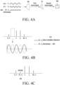
- the operation of combining the signals is described below in greater detail with reference to FIG. 4A .
- the driver 140 may convert the digital signal received from the DSP 130 into an analog signal and output the analog signal to the speaker 150.
- the speaker 150 may output (3) the first sound signal to the outside of the electronic device 100.
- the speaker 150 may be disposed on a part of the ear probe of the electronic device 100 to output the first sound signal.
- the microphone 160 may receive an external sound signal of the electronic device 100.
- the microphone 160 may receive the analog signal and convert it into a digital signal, and transfer the converted digital signal to the DSP 130.
- the microphone 160 may be disposed on a part of the ear probe of the electronic device 100 and, after the first sound signal is output through the speaker 150, receive (4) a second sound signal related to the output first sound signal.
- a distortion production otoacoustic emission signal generated in the cochlea of the user due to the output first sound signal may be included in the second sound signal related to the output first sound signal.
- the DSP 130 may extract (5) the distortion production otoacoustic emission signal from the second sound signal received through the microphone 160.
- the frequency of the distortion production otoacoustic emission signal may be 2f1-f2 based on the frequencies f1 and f2 of the two pure tone signals included in the first sound signal.
- the second sound signal received through the microphone 160 may be transferred to the processor 120.
- the operation of extracting the distortion production otoacoustic emission signal from the second sound signal may be performed by the processor 120.
- the processor 120 may measure external noise through the microphone 160 and determine whether to perform a hearing test based on the external noise measurement results.
- the processor 120 may obtain (6) the user's hearing profile based on the extracted distortion production otoacoustic emission signal. For example, the processor 120 may determine whether the user's hearing is normal in a specific frequency range based on the strength of the extracted distortion production otoacoustic emission signal relative to the strength of the first frequency signal and the strength of the second frequency signal included in the output first sound signal.
- the processor 120 may change protocols and repeat the operation of outputting the sound signal for a hearing test and the operation of extracting the distortion production otoacoustic emission signal.
- the processor 120 may obtain the user's hearing profile in a plurality of frequency ranges based on a plurality of distortion production otoacoustic emission signals.
- the processor 120 may perform (7) volume control change and/or equalization (EQ) change based on the obtained user hearing profile. For example, upon determining that the user's hearing is deteriorated based on the user hearing profile, the processor 120 may control the speaker 150 to reduce the volume of the output sound signal.
- EQ volume control change and/or equalization
- the processor 120 may change the equalization based on the user's hearing profile. Equalization refers to partially adjusting the sound signal from the low pitch to the high pitch according to the music genre or the user's taste. For example, the processor 120 may change the equalization so that the difference in strength (e.g., volume) between the plurality of frequencies included in the sound signal to be output falls within a set range based on the user's hearing profile.
- the difference in strength e.g., volume
- the processor 120 may change the equalization to reduce the volume of a specific frequency signal in the sound signal based on the user's hearing profile.
- the processor 120 may update the user's hearing profile with the pre-stored equalization. According to another embodiment, when the user's personal equalization is absent, the processor 120 may store the equalization changed based on the user's hearing profile.
- the processor 120 may provide feedback to notify the user that her hearing is deteriorated. For example, upon determining that the user's hearing is deteriorated, the processor 120 may display a message indicating the deterioration of hearing on the display of the electronic device 100 or transmit it to an external device to display it on the display of the external device. In another embodiment, upon determining that the user's hearing is deteriorated, the processor 120 may output a notification of the deterioration of hearing through the speaker 150.
- the electronic device 100 may further include at least one of a communication module, a sensor, or a power supply unit.
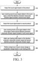
- FIG. 3 is a flowchart illustrating a method for controlling an electronic device using distortion production otoacoustic emissions according to an embodiment.
- the electronic device 100 may output a first sound signal based on a first protocol.
- the electronic device 100 may output, through the speaker 150, a first sound signal obtained by combining a plurality of signals using the first protocol among a plurality of protocols stored in the memory 110.
- the electronic device 100 may output the first sound signal through the speaker 150 corresponding to one ear using one channel.
- the electronic device 100 may output, through the speaker 150, the first sound signal which is a combination of a first signal 410 whose frequency is f1, a second signal 411 whose frequency is f2, and an anti-phase signal 420 of 2f1-f2 which is a frequency related to the distortion production otoacoustic emission of f1 and f2.
- combining two signals to output signals of two different frequencies through one channel may cause a plurality of inter-modulation distorted signals. For example, if the first signal 410 whose frequency is f1 and the second signal 411 whose frequency is f2 are combined, a plurality of inter-modulation distorted signals having frequencies of f2-f1, 2f1-f2, and 2f2-f1 are generated.
- the electronic device 100 may output, through the speaker 150, the first sound signal in which the inter-modulation distorted signal of the frequency 2f1-f ⁇ z among the plurality of inter-modulation distorted signals of f1 and f2 has been canceled out by further combining the anti-phase signal 420 of the inter-modulation distorted signal 412 having the frequency of 2f1-f ⁇ z which is the frequency related to the distortion production otoacoustic emission of f1 and f2 among the plurality of inter-modulation distorted signals.
- the electronic device 100 may extract the first distortion production otoacoustic emission signal included in the second sound signal.
- the electronic device 100 may output the first sound signal through the speaker 150 and then receive the second sound signal through the microphone 160.
- the second sound signal received through the microphone 160 after the first sound signal is output may include a distortion production otoacoustic emission (DPOAE) signal 430 generated from the ear of the user 10, and the electronic device 100 may extract the distortion production otoacoustic emission (DPOAE) signal 430 from the second sound signal.
- DPOAE distortion production otoacoustic emission
- the first sound signal in which the inter-modulation distorted signal 412 whose frequency is 2f1-f ⁇ z among the plurality of inter-modulation distorted signals of f1 and f2 has been canceled out is output.
- the distortion production otoacoustic emission signal 430 generated from the cochlea of the user 10, stimulated by the pure tone signals whose frequencies are f1 and f2, may be precisely extracted.
- the electronic device 100 may output a third sound signal based on a second protocol.
- the electronic device 100 may output, through the speaker 150, a third sound signal obtained by combining a plurality of signals using the second protocol among a plurality of protocols stored in the memory 110.
- the electronic device 100 may output the third sound signal through the speaker 150 corresponding to one ear using one channel.
- the electronic device 100 may output, through the speaker 150, the third sound signal which is a combination of a pure tone signal whose frequency is f3, a pure tone signal whose frequency is f4, and an anti-phase signal of 2f3-f4 which is a frequency related to the distortion production otoacoustic emission of f3 and f4.
- the electronic device 100 may extract the second distortion production otoacoustic emission signal included in the fourth sound signal.
- the electronic device 100 may output the third sound signal through the speaker 150 and then receive the fourth sound signal through the microphone 160.
- the fourth sound signal received through the microphone 160 after the third sound signal is output may include the distortion production otoacoustic emission signal generated from the cochlea of the user 10 stimulated by the pure tone signal whose frequency is f3 and the pure tone signal whose frequency is f4, and the electronic device 100 may extract the distortion production otoacoustic emission signal from the fourth sound signal.
- the electronic device 100 may repeat the operation of outputting the sound signal whose frequency is changed and the operation of extracting the distortion production otoacoustic emission signal for the output sound based on the plurality of protocols.
- the electronic device 100 may obtain the user's hearing profile based on the first distortion production otoacoustic emission signal and the second distortion production otoacoustic emission signal. For example, the electronic device 100 may obtain the user's hearing profile in a plurality of frequency ranges based on a plurality of distortion production otoacoustic emission signals.
- the electronic device 100 may perform at least one of volume change or equalization change based on the user's hearing profile. For example, upon determining that the user's hearing is deteriorated based on the user hearing profile, the electronic device 100 may control the speaker 150 to reduce the volume of the output sound signal or change the equalization to reduce the volume of a specific frequency signal.
- the electronic device 100 may update the user's hearing profile with the pre-stored equalization.
- the user's personal equalization may be stored in the memory 110 of the electronic device 100 or received from an external device through the communication module.
- the electronic device 100 may store the equalization changed based on the user's hearing profile.
- the electronic device 100 may provide a message to notify the user that her hearing is deteriorated.
- FIGS. 5A and B are views illustrating a sound signal output from a speaker according to an embodiment of the disclosure.
- the electronic device of the disclosure may output a sound signal to a 2cc coupler 20.
- the 2cc coupler 20 is a component used for performance analysis of a hearing aid, and may have a 2cc space similar to the volume of the user's ear canal. Although only the 2cc coupler 20 is shown in FIG. 5A , a coupler having a volume other than 2cc may be used depending on the volume of the user's ear canal.
- the 2cc coupler 20 may have a linear characteristic. The linear characteristic may mean that when a sound signal having a plurality of frequencies is output to the 2cc coupler 20, no inter-modulation distorted sound for a plurality of frequencies is included in the reflection signal of the output sound signal. In other words, no inter-modulation distorted sound is generated for the sound signal having a plurality of frequencies through the 2cc coupler 20.
- the electronic device may output, to the 2cc coupler 20 through the speaker, each of the sound signal 510 obtained by combining a signal whose frequency is f1 and a signal whose frequency is f2 and a sound signal 520 obtained by combining a signal whose frequency is f1, a signal whose frequency is f2, and an anti-phase signal 521 of 2f1-f ⁇ z which is a frequency related to the distortion production otoacoustic emission of f1 and f2.
- the electronic device may measure the strength of the signal of the frequency (e.g., third-order low frequency inter-modulation distortion) related to the distortion production otoacoustic emission included in the reflection signal obtained from the 2cc coupler 20.
- the frequency e.g., third-order low frequency inter-modulation distortion
- the strength of the signal 530 having the frequency related to the distortion production otoacoustic emission included in the reflection signal of the sound signal 510 obtained by combining the signal of f1 and the signal of f2 may be about 7dBSPL.
- the strength of the signal 540 having the frequency related to the distortion production otoacoustic emission included in the reflection signal of the sound signal 520 obtained by combining the signal of f1, the signal of f2, and the anti-phase signal 521 of 2f1-f ⁇ z which is the frequency related to the distortion production otoacoustic emission of f1 and f2 may be about 1dBSPL.
- the signal having the frequency related to distortion production otoacoustic emission is canceled in the sound signal output through the speaker by destructive interference by combining the anti-phase signal of 2f1-f2 which is the frequency related to the distortion production otoacoustic emission of f1 and f2.
- FIGS. 6A and B are views illustrating a sound signal input from a user's ear according to an embodiment of the disclosure.
- the electronic device of the disclosure may output a sound signal to an ear of the user 10.
- the ear of the user 10 may have a non-linear characteristic.
- the non-linear characteristic may mean that when a sound signal having a plurality of frequencies is output to the ear of the user 10, an inter-modulation distorted sound for a plurality of frequencies is included in the reflection signal of the output sound signal.
- the inter-modulation distorted sound included in the reflection signal may be a third-order low-frequency inter-modulation distorted sound.
- the electronic device may output, to the ear of the user 10 through the speaker, each of the sound signal 610 obtained by combining a signal whose frequency is f1 and a signal whose frequency is f2 and a sound signal 620 obtained by combining a signal whose frequency is f1, a signal whose frequency is f2, and an anti-phase signal 621 of 2f1-f ⁇ z which is a frequency related to the distortion production otoacoustic emission of f1 and f2.
- the electronic device may measure the strength of the signal of the frequency (e.g., third-order low frequency inter-modulation distortion) related to the distortion production otoacoustic emission included in the reflection signal obtained from the ear of the user 10.
- a speaker may be disposed on each of both ears of the user 10, and the sound signal 610 or 620 may be output through each speaker.
- the strength of the signal 630 having the frequency related to the distortion production otoacoustic emission included in the reflection signal of the sound signal 610 obtained by combining the signal of f1 and the signal of f2 may be about 6dB for the left ear and about 5.5dB for the right ear.
- the strength of the signal 640 having the frequency related to the distortion production otoacoustic emission included in the reflection signal of the sound signal 620 obtained by combining the signal of f1, the signal of f2, and the anti-phase signal 621 of 2f1-f ⁇ z which is the frequency related to the distortion production otoacoustic emission of f1 and f2 may be about 19dB for the left ear and about 19dB for the right ear.
- 6B illustrates that when the anti-phase signal is not applied, the distortion production otoacoustic emission signal generated from the user's ear is canceled out with the inter-modulation distorted signals of f1 and f2 output through the speaker, but it may rather be reinforced, rendering it difficult to precisely measure the user's hearing.
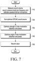
- FIG. 7 is a view illustrating an operation for determining an anti-phase signal of a distortion production otoacoustic emission frequency to be combined with a sound signal according to an embodiment of the disclosure.
- the electronic device of the disclosure may measure the sound volume (sound pressure level) per frequency and calibrate the speaker and the internal microphone. According to various embodiments, calibration may be performed before the electronic device is shipped out.
- the electronic device may output the sound signal while changing the sound volume per frequency through the speaker and compare the output sound signal with the result of measurement using a sound level meter.
- the comparison result is described with reference to FIG. 8A .
- the electronic device may compare the result of measurement using the sound level meter and the result of measurement through the microphone of the electronic device, for the sound signal output through the speaker.
- the comparison result is described with reference to FIG. 8B .
- FIG. 8A is a view illustrating the results of comparison between the sound volume of the sound signal (e.g., pure tone signal) output from the speaker of the electronic device and the sound volume measured by the sound level meter.
- the sound volume of the sound signal e.g., pure tone signal
- the electronic device may sequentially change (e.g., -30dBV to -120dBv) the sound volume of the sound signal (e.g., pure tone signal) having a specific frequency (e.g., f1(2kHz)) and a specific phase (e.g., 0°, 90°, 180°, 270°) while outputting through the speaker and measure the sound volume of the output sound signal using the sound level meter.
- the sound volume of the sound signal e.g., pure tone signal
- a specific frequency e.g., f1(2kHz)
- a specific phase e.g., 0°, 90°, 180°, 270°
- the electronic device may calibrate the characteristics of the speaker in the specific range.
- FIG. 8B is a view illustrating the results of comparison between the sound volume of the sound signal input through the microphone of the electronic device and the sound volume of the sound signal measured by the sound level meter.
- the sound signal input through the microphone and the sound signal measured by the sound level meter may be ones output through the speaker of the electronic device.
- the electronic device may sequentially change (e.g., -30dBV to -120dBv) the sound volume of the sound signal (e.g., pure tone signal) having a specific frequency (e.g., f1(2kHz)) and a specific phase (e.g., 0°, 90°, 180°, 270°) while outputting through the speaker and measure the sound volume of the output sound signal using the sound level meter.
- the sound volume of the sound signal e.g., pure tone signal
- a specific frequency e.g., f1(2kHz)
- a specific phase e.g., 0°, 90°, 180°, 270°
- the electronic device may calibrate the characteristics of the microphone in the specific range.
- the electronic device may sub-optimize the sound source of the distortion production otoacoustic emission (DPOAE). For example, the electronic device may identify whether it is input in the sound volume expected for the output sound volume of the sound signal in which a plurality of frequencies (e.g., f1 and f ⁇ z) to be used for a hearing test using distortion production otoacoustic emission are combined.
- a plurality of frequencies e.g., f1 and f ⁇ z
- the signal of the frequency e.g., 2f1-f2
- the electronic device may output the sound signal in which the signals of the plurality of frequencies (e.g., f1 and f2) each having a specific sound volume are combined to the 2cc coupler through the speaker, receive the signal reflected from the 2cc coupler through the microphone, and identify the input sound volume relative to the output sound volume.
- the signals of the plurality of frequencies e.g., f1 and f2
- the electronic device may optimize the strength of the inter-modulation distortion anti-phase signal.
- the frequency of the inter-modulation distortion anti-phase signal may be a frequency (e.g., 2f1-f ⁇ z) related to the distortion production otoacoustic emission for the two frequencies (e.g., f1 and f2).
- the frequency related to distortion production otoacoustic emission may be denoted as 2f1-f2 for convenience of description.
- the electronic device may output the signal to the 2cc coupler through the speaker while changing (e.g., -30dBV to -120dBV) the strength of the anti-phase signal of 2f1-f ⁇ z included in the sound signal and measure the strength of the anti-phase signal of 2f1-f ⁇ z included in the sound signal input through the microphone.
- changing e.g., -30dBV to -120dBV
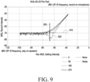
- the measurement result is described with reference to FIG. 9 .
- the magnitude of the inter-modulation distorted sound 910 of 2f1-f2 included in the sound signal input through the microphone is about -70dBV.
- the optimal strength 930 of the anti-phase signal of 2f1-f2 in the electronic device is -70dBV.
- the strength of the signal of 2f1-f2 input through the microphone when the anti-phase signal of 2f1-f ⁇ z is not combined is measured, and the strength of the anti-phase signal of 2f1-f2 in which the strength of the signal of 2f1-f2 input through the microphone is reduced is measured while changing the strength of the anti-phase signal of 2f1-fl.
- the electronic device may estimate the strength of the signal of 2f1-f ⁇ z to be input through the microphone.
- the electronic device may calculate the strength of the anti-phase signal of 2f1-f ⁇ z to be combined with the sound signal to be output through the speaker, based on the estimated strength of the signal of 2f1-fl.
- the electronic device may optimize the angle of the inter-modulation distortion anti-phase signal.
- the electronic device may output the sound signal obtained by combining the f1 signal and f2 signal having a specific sound volume and the anti-phase signal of 2f1-f ⁇ z with a determined strength through the speaker to the 2cc coupler and measure the strength of the signal of 2f1-f ⁇ z included in the sound signal input through the microphone.
- the electronic device may fix the phases of the f1 signal and the f2 signal included in the sound signal output through the speaker to 0° while changing the phase of the anti-phase signal of 2f1-f ⁇ z (e.g., 0° to 360°).
- the electronic device may change the phase of the anti-phase signal of 2f1-f2 in units of 1°.
- the strength of the signal 1010 of 2f1-f2 included in the sound signal input through the microphone when outputting a sound signal not including the anti-phase signal of 2f1-f ⁇ z through the speaker may be about -70dBV.
- the strength of the signal 1020 of 2f1-f2 input through the microphone may be as low as about - 81dBV. This is why the inter-modulation distorted sound of 2f1-f2 generated when f1 and f2 are combined in the filter of the speaker is most canceled out by the anti-phase signal of 2f1-f ⁇ z with a phase of 25° combined with f1 and f2.
- the electronic device may record the measured values.
- the strength of the anti-phase signal of the signal of the frequency related to distortion production otoacoustic emission generated due to the combination in the filter is less than a set value
- the strength of the anti-phase signal of the signal of the frequency related to distortion production otoacoustic emission may be 0. Accordingly, the strength of the anti-phase signal of the signal of the frequency related to distortion production otoacoustic emission included in the protocol may be 0.
- the electronic device may perform calibration on the speaker and the microphone using the space of the cradle device.
- the cradle device may be a device for charging and/or storing the electronic device.
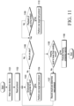
- FIG. 11 is a view illustrating a hearing test operation by an electronic device according to an embodiment of the disclosure.
- the electronic device may obtain a protocol.
- the electronic device may obtain a plurality of protocols stored in the memory or a plurality of protocols received from an external device.
- each of the plurality of protocols may include information about the frequencies of two pure tone signals, information about the frequency related to distortion production otoacoustic emission of the two pure tone signals, information about the strengths of the two pure tone signals, information about the strength of the anti-phase signal of the frequency related to the distortion production otoacoustic emission, and information about the angle of the anti-phase signal of the frequency related to the distortion production otoacoustic emission.
- the electronic device may identify whether the noise in the ambient environment is less than a set value. For example, if the strength of the sound signal (e.g., noise) received through the microphone before outputting the sound signal for the hearing test is less than a set value, the electronic device may determine that the environment is appropriate for the hearing test.
- the sound signal e.g., noise
- the electronic device may determine that the environment is not appropriate for the hearing test if a content sound signal is being output through the speaker. For example, if music is playing, the sound signal of video content is being output, or a call voice is being output through the speaker, the electronic device may determine that the environment is not appropriate for the hearing test.
- the electronic device may perform one target test protocol among the plurality of protocols in operation 1104.
- the electronic device may output, through the speaker, the sound signal obtained by combining the two frequency signals related to the hearing frequency range to be tested and the signal of the frequency related to the distortion production otoacoustic emission of the two frequencies based on one protocol and measure the strength of the signal of the frequency related to the distortion production otoacoustic emission included in the sound signal input through the microphone, thereby testing the user's hearing.
- the electronic device may execute a hearing protection service in operation 1106.
- the electronic device may provide a feedback for hearing protection.
- the electronic device may display a message through the display or transmit a message to an external device to display the message on the display of the external device or may output an audible notification through the speaker.
- the electronic device may provide feedback recommending ear rest, in-depth test or sound volume reduction, or feedback indicating ear fatigue or may automatically reduce the sound volume of the tested frequency range and output it.
- the electronic device may record the test result of the tested frequency range and determine a next protocol to perform test in operation 1107.
- the order of performing protocols may be set, or a protocol related to the frequency range in which a section with a large sound volume is frequent among the plurality of frequency ranges of the sound signal often listened to by the user may be determined to be the next protocol to perform test.
- the electronic device may return to operation 1103 to determine whether the environment is appropriate for the hearing test.
- the electronic device may determine whether music is playing in operation 1108. According to various embodiments, unless music is playing (no in operation 1108), the electronic device may return to operation 1103 to determine whether it is an environment appropriate for the hearing test. According to various embodiments, the electronic device may provide feedback to request to move a quiet environment or a request to rewear the electronic device to the user.
- the electronic device may determine whether playback of one song is ended in operation 1109. If playback of one song is not ended (no in 1109), the electronic device may determine again whether playback of one song is ended. When playback of one song is ended (yes in 1109), the electronic device may perform one target test protocol in operation 1110. For example, the electronic device may perform one test protocol before playing the next song after playback of one song is ended.
- the electronic device may output, through the speaker, the sound signal obtained by combining the two frequency signals related to the hearing frequency range to be tested and the signal of the frequency related to the distortion production otoacoustic emission of the two frequencies based on one protocol and measure the strength of the signal of the frequency related to the distortion production otoacoustic emission included in the sound signal input through the microphone, thereby testing the user's hearing.
- FIG. 9 illustrates that a hearing test is performed between song playbacks but, according to various embodiments, the electronic device may play music for a hearing test reflecting a hearing test protocol or play a sound signal (e.g., music) of sound signal-inserted content based on the hearing test protocol. For example, the electronic device may analyze the sound signal of the content and insert a hearing test protocol-based sound signal to a section where insertion of the hearing test protocol-based sound signal does not bother listening to the content sound signal.
- a sound signal e.g., music
- the electronic device may perform at least one of operation 1105, operation 1106, or operation 1107 based on the result of performing the protocol in operation 1110.
- FIG. 12 is a view illustrating an operation for outputting a sound signal based on a user's hearing profile obtained according to an embodiment of the disclosure.
- the following description assumes that the wearing of the electronic device on the user's ear is detected.
- a hearing test may be performed based on a set period (e.g., one moth or one week), whenever the electronic device is worn on the user's ear, or when the user inputs a manipulation command for a hearing test.
- the electronic device 100 may output a first sound signal based on a protocol.
- the electronic device 100 may output, through the speaker, a first sound signal obtained by combining two frequency signals related to a hearing frequency range to be tested based on the protocol and a signal of a frequency related to distortion production otoacoustic emission of the two frequencies.
- the protocol may be stored in the electronic device 100 or be received from an external device 200.
- the external device 200 is a component to communicate with the electronic device 100 and may be a terminal device connected with the electronic device 100 which is an earphone.
- the electronic device 100 may receive a second sound signal related to the first sound signal through the microphone.
- the electronic device 100 may transmit the received second sound signal to the external device 200.
- the external device 200 may extract a first distortion production otoacoustic emission signal included in the second sound signal received from the electronic device 100.
- FIG. 12 illustrates that the external device 200 extracts the first distortion production otoacoustic emission signal included in the second sound signal received from the electronic device 100 but, according to various embodiments, the electronic device 100 may extract the first distortion production otoacoustic emission signal included in the second sound signal and transmit the extracted first distortion production otoacoustic emission signal to the external device 200.
- the external device 200 may obtain the user's hearing profile based on the first distortion production otoacoustic emission signal.
- FIG. 12 illustrates that the user's hearing profile is obtained based on the first distortion production otoacoustic emission signal obtained based on one protocol but, according to various embodiments, the external device 200 may obtain the user's hearing profile for a plurality of frequency ranges based on a plurality of distortion production otoacoustic emission signals obtained based on a plurality of protocols.
- the external device 200 may store the obtained user hearing profile.
- the external device 200 may transmit the user hearing profile to the electronic device 100.
- the electronic device 100 may perform at least one of sound volume change or equalization change based on the user hearing profile received from the external device 200.
- the electronic device 100 may reduce the sound volume.
- the electronic device 100 may change the equalization to reduce the sound volume of a specific frequency signal in the sound signal based on the user hearing profile or change the equalization so that the difference between the strengths (e.g., sound volumes) of the plurality of frequencies included in the sound signal to be output falls within a set range.
- the strengths e.g., sound volumes
- the electronic device 100 may provide visual feedback (e.g., display of a message) and/or audible feedback (e.g., output of a notification) indicating that the user's hearing is deteriorated.
- the external device 200 may also provide visual feedback and/or audible feedback to indicate that the user's hearing is deteriorated based on the obtained user hearing profile.
- the external device 200 may transmit the content sound signal to the electronic device 100 and, in operation 1209, the electronic device 100 may output the content sound signal based on at least one of the changed sound volume or changed equalization.
- FIG. 13 is a view illustrating an operation for outputting a sound signal based on a user's hearing profile obtained according to an embodiment of the disclosure.
- the following description assumes that the wearing of the electronic device on the user's ear is detected.
- a hearing test may be performed based on a set period (e.g., one moth or one week), whenever the electronic device is worn on the user's ear, or when the user inputs a manipulation command for a hearing test.
- the electronic device 100 may output a first sound signal based on a protocol.
- the electronic device 100 may receive a second sound signal related to the first sound signal through the microphone.
- the electronic device 100 may transmit the received second sound signal to the external device 200.
- the external device 200 may extract a first distortion production otoacoustic emission signal included in the second sound signal received from the electronic device 100.
- FIG. 13 illustrates that the external device 200 extracts the first distortion production otoacoustic emission signal included in the second sound signal received from the electronic device 100 but, according to various embodiments, the electronic device 100 may extract the first distortion production otoacoustic emission signal included in the second sound signal and transmit the extracted first distortion production otoacoustic emission signal to the external device 200.
- the external device 200 may obtain the user's hearing profile based on the first distortion production otoacoustic emission signal.
- FIG. 13 illustrates that the user's hearing profile is obtained based on the first distortion production otoacoustic emission signal obtained based on one protocol but, according to various embodiments, the external device 200 may obtain the user's hearing profile for a plurality of frequency ranges based on a plurality of distortion production otoacoustic emission signals obtained based on a plurality of protocols.
- the external device 200 may store the obtained user hearing profile.
- Operations 1301 to 1305 in FIG. 13 are the same as operations 1201 to 1205 in FIG. 12 , and thus, no duplicate description thereof is given.
- the external device 200 may perform at least one of sound volume change or equalization change of the content sound signal based on the user's hearing profile.
- the external device 200 may reduce the sound volume.
- the external device 200 may change the equalization to reduce the sound volume of a specific frequency signal in the sound signal based on the user hearing profile or change the equalization so that the difference between the strengths (e.g., sound volumes) of the plurality of frequencies included in the sound signal to be output falls within a set range.
- the strengths e.g., sound volumes
- the external device 200 may transmit a content sound signal to which at least one of the changed sound volume or the changed equalization has been applied to the electronic device 100.
- the electronic device 100 may output the content sound signal received from the external device 200 through the speaker.
- the electronic device 100 may provide visual feedback (e.g., display of a message) and/or audible feedback (e.g., output of a notification) indicating that the user's hearing is deteriorated.
- the external device 200 may also provide visual feedback and/or audible feedback to indicate that the user's hearing is deteriorated based on the obtained user hearing profile.
- FIG. 14 is a view illustrating an operation for outputting a sound signal based on a user's hearing profile obtained according to an embodiment of the disclosure.
- the external device 200 of FIG. 14 may perform generation and analysis of the sound signal for a hearing test of the disclosure, and the electronic device 100 may only perform the operations of outputting the sound signal received from the external device 200 and transmitting the sound signal input through the microphone to the external device 200.
- the following description assumes that the wearing of the electronic device on the user's ear is detected.
- a hearing test may be performed based on a set period (e.g., one moth or one week), whenever the electronic device is worn on the user's ear, or when the user inputs a manipulation command for a hearing test.
- the external device 200 may obtain a first sound signal based on a protocol.
- the external device 200 may generate a first sound signal obtained by combining two frequency signals related to a hearing frequency range to be tested based on the protocol and a signal of a frequency related to distortion production otoacoustic emission of the two frequencies.
- the external device 200 may transmit the first sound signal to the electronic device 100 and, in operation 1403, the electronic device 100 may output the received first sound signal through the speaker.
- the electronic device 100 may receive a second sound signal related to the first sound signal through the microphone.
- the electronic device 100 may transmit the received second sound signal to the external device 200.
- the external device 200 may extract a first distortion production otoacoustic emission signal included in the second sound signal received from the electronic device 100.
- the external device 200 may obtain the user's hearing profile based on the first distortion production otoacoustic emission signal.
- FIG. 14 illustrates that the user's hearing profile is obtained based on the first distortion production otoacoustic emission signal obtained based on one protocol but, according to various embodiments, the external device 200 may obtain the user's hearing profile for a plurality of frequency ranges based on a plurality of distortion production otoacoustic emission signals obtained based on a plurality of protocols.
- the external device 200 may store the obtained user hearing profile.
- the external device 200 may perform at least one of sound volume change or equalization change of the content sound signal based on the user's hearing profile.
- the external device 200 may transmit a content sound signal to which at least one of the changed sound volume or the changed equalization has been applied to the electronic device 100.
- the electronic device 100 may output the content sound signal received from the external device 200 through the speaker.
- Operations 1404 to 1410 in FIG. 14 are the same as operations 1302 to 1308 in FIG. 13 , and thus, no duplicate description thereof is given.
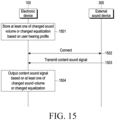
- FIG. 15 is a view illustrating an operation for outputting a sound signal based on a user's hearing profile obtained according to an embodiment of the disclosure.
- the electronic device 100 may store at least one of the changed sound volume or the changed equalization based on the user hearing profile.
- the user hearing profile may be obtained by the electronic device 100 or obtained by a terminal device (e.g., the external device 200) connected with the electronic device 100 and received by the electronic device 100.
- the changed sound volume and/or the changed equalization may be one changed by the electronic device 100 or one changed by a terminal device connected with the electronic device 100 and received by the electronic device 100.
- the electronic device 100 may be connected with an external sound device 300.
- the external sound device 300 may be a terminal device (e.g., the external device 200) previously connected with the electronic device 100 or another external device that is irrelevant to obtaining the user hearing profile.
- the electronic device 100 which is an earphone (or headset) may be connected to a different smartphone from a smartphone previously connected, or a sound device.
- the external sound device 300 may transmit a content sound signal to the electronic device 100.
- the electronic device 100 may output the content sound signal based on at least one of the changed sound volume or the changed equalization.
- the electronic device 100 may change at least one of the sound volume or equalization of the content sound signal received from the external sound device 300 based on the value stored in operation 1501 and output the changed content sound signal.
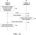
- FIG. 16 is a view illustrating an operation for outputting a sound signal based on a user's hearing profile obtained according to an embodiment of the disclosure.
- the electronic device 100 may store at least one of the changed sound volume or the changed equalization based on the user hearing profile.
- the user hearing profile may be obtained by the electronic device 100 or obtained by a terminal device (e.g., the external device 200) connected with the electronic device 100 and received by the electronic device 100.
- the changed sound volume and/or the changed equalization may be one changed by the electronic device 100 or one changed by a terminal device connected with the electronic device 100 and received by the electronic device 100.
- the electronic device 100 may be connected with an external sound device 300.
- the external sound device 300 may be a terminal device (e.g., the external device 200) previously connected with the electronic device 100 or another external device that is irrelevant to obtaining the user hearing profile.
- the electronic device 100 which is an earphone (or headset) may be connected to a different smartphone from a smartphone previously connected, or a sound device.
- the electronic device 100 may transmit the stored equalization to the external sound device 300.
- the external sound device 300 may generate a content sound signal based on the received equalization.
- FIG. 16 illustrates that the electronic device 100 transmits the equalization to the external sound device 300 but, according to various embodiments, the electronic device 100 may transmit a user hearing profile to the external sound device 300, and the external sound device 300 may generate a content sound signal in which the equalization has been changed, based on the received user hearing profile.
- the external sound device 300 may transmit a content sound signal to the electronic device 100.
- the electronic device 100 may output the content sound signal based on the stored sound volume.
- the disclosure it is possible to perform a hearing test based on distortion production otoacoustic emissions, only with one speaker for each ear. Further, according to various embodiments of the disclosure, it is possible to reduce the user's hearing loss by obtaining an equalization customized to fit the user's hearing condition based on the user hearing profile.
- outputting the first sound signal may output the first sound signal after completing the output of the content sound signal if a content sound signal is being output through the speaker before outputting the first sound signal.
- each of the plurality of protocols may include information about frequencies of two pure tone signals, information about a frequency related to a distortion production otoacoustic emission of the two pure tone signals, information about strengths of the two pure tone signals, information about a strength of an anti-phase signal of a frequency related to the distortion production otoacoustic emission, and information about an angle of the anti-phase signal of the frequency related to the distortion production otoacoustic emission.
- the strength of the anti-phase signal of the frequency related to the distortion production otoacoustic emission may be 0.
- the method may further comprise performing calibration on the speaker and the microphone upon detecting a contact of the electronic device to a cradle device corresponding to the electronic device.
- the method may further comprise storing at least one of the changed sound volume or the changed equalization, transmitting the stored equalization to an external device through a communication module of the electronic device, receiving a content sound signal to which the stored equalization is applied, from the external device, and outputting the received content sound signal through the speaker based on the stored sound volume.
- the electronic device may be one of various types of electronic devices.
- the electronic devices may include, for example, a portable communication device (e.g., a smartphone), a computer device, a portable multimedia device, a portable medical device, a camera, a wearable device, or a home appliance.
- a portable communication device e.g., a smartphone
- a computer device e.g., a laptop, a desktop, a tablet, or a portable multimedia device
- a portable medical device e.g., a portable medical device
- camera e.g., a camera
- a wearable device e.g., a portable medical device
- module may include a unit implemented in hardware, software, or firmware, and may interchangeably be used with other terms, for example, “logic,” “logic block,” “part,” or “circuitry”.
- a module may be a single integral component, or a minimum unit or part thereof, adapted to perform one or more functions.
- the module may be implemented in a form of an application-specific integrated circuit (ASIC).
- ASIC application-specific integrated circuit
- Various embodiments as set forth herein may be implemented as software (e.g., the program) including one or more instructions that are stored in a storage medium (e.g., internal memory or external memory) that is readable by a machine (e.g., the electronic device 100).
- a processor e.g., the processor 120 of the machine (e.g., the electronic device 100) invokes at least one of the one or more instructions stored in the storage medium, and execute it, with or without using one or more other components under the control of the processor. This allows the machine to be operated to perform at least one function according to the at least one instruction invoked.
- the one or more instructions may include a code generated by a compiler or a code executable by an interpreter.
- the machine-readable storage medium may be provided in the form of a non-transitory storage medium.
- non-transitory simply means that the storage medium is a tangible device, and does not include a signal (e.g., an electromagnetic wave), but this term does not differentiate between where data is semi-permanently stored in the storage medium and where the data is temporarily stored in the storage medium.
- a method may be included and provided in a computer program product.
- the computer program products may be traded as commodities between sellers and buyers.
- the computer program product may be distributed in the form of a machine-readable storage medium (e.g., compact disc read only memory (CD-ROM)), or be distributed (e.g., downloaded or uploaded) online via an application store (e.g., Play Store TM ), or between two user devices (e.g., smart phones) directly. If distributed online, at least part of the computer program product may be temporarily generated or at least temporarily stored in the machine-readable storage medium, such as memory of the manufacturer's server, a server of the application store, or a relay server.
- CD-ROM compact disc read only memory
- an application store e.g., Play Store TM
- two user devices e.g., smart phones
- each component e.g., a module or a program of the above-described components may include a single entity or multiple entities. Some of the plurality of entities may be separately disposed in different components. According to various embodiments, one or more of the above-described components may be omitted, or one or more other components may be added. Alternatively or additionally, a plurality of components (e.g., modules or programs) may be integrated into a single component. In such a case, according to various embodiments, the integrated component may still perform one or more functions of each of the plurality of components in the same or similar manner as they are performed by a corresponding one of the plurality of components before the integration.
- operations performed by the module, the program, or another component may be carried out sequentially, in parallel, repeatedly, or heuristically, or one or more of the operations may be executed in a different order or omitted, or one or more other operations may be added.
Landscapes
- Health & Medical Sciences (AREA)
- Life Sciences & Earth Sciences (AREA)
- Engineering & Computer Science (AREA)
- Physics & Mathematics (AREA)
- General Health & Medical Sciences (AREA)
- Acoustics & Sound (AREA)
- Otolaryngology (AREA)
- Animal Behavior & Ethology (AREA)
- Biophysics (AREA)
- Medical Informatics (AREA)
- Molecular Biology (AREA)
- Surgery (AREA)
- Biomedical Technology (AREA)
- Pathology (AREA)
- Public Health (AREA)
- Veterinary Medicine (AREA)
- Heart & Thoracic Surgery (AREA)
- Signal Processing (AREA)
- Audiology, Speech & Language Pathology (AREA)
- Multimedia (AREA)
- Physiology (AREA)
- Neurosurgery (AREA)
- Computer Networks & Wireless Communication (AREA)
- Artificial Intelligence (AREA)
- Computer Vision & Pattern Recognition (AREA)
- Psychiatry (AREA)
- Circuit For Audible Band Transducer (AREA)
Claims (14)
- Elektronische Vorrichtung (100), umfassend:einen Lautsprecher (150);ein Mikrofon (160);einen digitalen Signalprozessor, DSP, (130);einen Treiber (140), der konfiguriert ist, um ein vom DSP (130) ausgegebenes digitales Signal in ein analoges Signal zu wandeln und das analoge Signal an den Lautsprecher (150) auszugeben;einen Prozessor (120); undeinen Speicher (110), der Befehle speichert, die bei Ausführung durch den Prozessor (120) die elektronische Vorrichtung (100) veranlassen zum:Steuern des DSP (130) und des Treibers (140), um über den Lautsprecher (150) ein erstes Tonsignal auszugeben, das durch Kombinieren eines Signals einer ersten Frequenz, eines Signals einer zweiten Frequenz und eines gegenphasigen Signals einer dritten Frequenz erhalten wird, das sich auf eine verzerrungserzeugende otoakustische Emission, DPOAE, der ersten Frequenz und der zweiten Frequenz bezieht, basierend auf einem ersten Protokoll aus einer Vielzahl von Protokollen, die in dem Speicher gespeichert sind;beim Empfang eines zweiten Tonsignals, das mit dem ersten Tonsignal in Beziehung steht, über das Mikrofon (160), Extrahieren eines ersten DPOAE-Signals der dritten Frequenz, die in dem zweiten Tonsignal enthalten ist;Steuern des DSP (130) und des Treibers (140), um über den Lautsprecher (150) ein drittes Tonsignal auszugeben, das durch Kombinieren eines Signals einer vierten Frequenz, eines Signals einer fünften Frequenz und eines gegenphasigen Signals einer sechsten Frequenz erhalten wird, das sich auf eine DPOAE der vierten Frequenz und der fünften Frequenz bezieht, basierend auf einem zweiten Protokoll aus der Vielzahl von Protokollen;beim Empfang eines vierten Tonsignals, das mit dem dritten Tonsignal in Beziehung steht, über das Mikrofon (160), Extrahieren eines zweiten DPOAE-Signals der sechsten Frequenz, die in dem vierten Tonsignal enthalten ist;Erhalten eines Hörprofils des Benutzers basierend auf dem ersten DPOAE-Signal und dem zweiten DPOAE-Signal; undDurchführen mindestens eines von einer Lautstärkesteuerung, einer Laustärkeänderung oder einer Entzerrungs-, EQ-,Änderung eines Tons basierend auf dem Hörprofil des Benutzers.
- Elektronische Vorrichtung (100) nach Anspruch 1, wobei die Anweisungen, wenn sie von dem Prozessor (120) ausgeführt werden, die elektronische Vorrichtung veranlassen, die Entzerrung so zu ändern, dass ein Unterschied in der Stärke zwischen einer Vielzahl von Frequenzen, die in einem auszugebenden Ton enthalten sind, basierend auf dem Hörprofil des Benutzers in einen festgelegten Bereich fällt.
- Elektronische Vorrichtung (100) nach Anspruch 1 oder 2, wobei die Anweisungen, wenn sie von dem Prozessor (120) ausgeführt werden, die elektronische Vorrichtung veranlassen, eine Rückmeldung zu geben, um anzuzeigen, dass das Hörvermögen des Benutzers schlechter geworden ist, basierend auf dem Hörprofil des Benutzers.
- Elektronische Vorrichtung (100) nach einem der vorhergehenden Ansprüche, wobei die Anweisungen, wenn sie von dem Prozessor (120) ausgeführt werden, die elektronische Vorrichtung veranlassen, das erste Tonsignal auszugeben, falls eine Stärke eines über das Mikrofon empfangenen Tonsignals vor der Ausgabe des ersten Tonsignals geringer als ein festgelegter Wert ist.
- Elektronische Vorrichtung (100) nach einem der vorhergehenden Ansprüche, wobei die Anweisungen, wenn sie von dem Prozessor (120) ausgeführt werden, die elektronische Vorrichtung dazu veranlassen, wenn ein Inhaltstonsignal über den Lautsprecher ausgegeben wird, bevor das erste Tonsignal ausgegeben wird, das erste Tonsignal auszugeben, nachdem die Ausgabe des Inhaltstonsignals abgeschlossen ist.
- Elektronische Vorrichtung (100) nach einem der vorhergehenden Ansprüche, wobei die Anweisungen, wenn sie von dem Prozessor (120) ausgeführt werden, die elektronische Vorrichtung veranlassen, das erste Tonsignal basierend auf einer festgelegten Periode auszugeben.
- Elektronische Vorrichtung (100) nach einem der vorhergehenden Ansprüche, wobei jedes der Vielzahl von Protokollen Informationen über Frequenzen von zwei Reintonsignalen, Informationen über eine Frequenz in Bezug auf eine DPOAE der zwei Reintonsignale, Informationen über Stärken der zwei Reintonsignale, Informationen über eine Stärke eines gegenphasigen Signals einer Frequenz in Bezug auf die DPOAE und Informationen über einen Winkel des gegenphasigen Signals der Frequenz in Bezug auf die DPOAE beinhaltet.
- Elektronische Vorrichtung (100) nach Anspruch 7, wobei in mindestens einigen der Vielzahl von Protokollen die Stärke des gegenphasigen Signals der auf die DPOAE bezogenen Frequenz 0 ist.
- Elektronische Vorrichtung (100) nach einem der vorhergehenden Ansprüche, ferner umfassend eine Ohrsonde, die in das Außenohr des Benutzers eingeführt wird,
wobei der Lautsprecher (150) und das Mikrofon (160) an einem Abschnitt der Ohrsonde angeordnet sind. - Elektronische Vorrichtung (100) nach einem der vorhergehenden Ansprüche, wobei die Anweisungen, wenn sie von dem Prozessor (120) ausgeführt werden, die elektronische Vorrichtung veranlassen, eine Kalibrierung des Lautsprechers (150) und des Mikrofons (160) durchzuführen, wenn ein Kontakt der elektronischen Vorrichtung (100) mit einer der elektronischen Vorrichtung (100) entsprechenden Wiegevorrichtung erkannt wird.
- Elektronische Vorrichtung (100) nach einem der vorhergehenden Ansprüche, ferner umfassend ein Kommunikationsmodul,
wobei die Anweisungen, wenn sie von dem Prozessor (120) ausgeführt werden, die elektronische Vorrichtung veranlassen zum:Speichern von mindestens einem der geänderten Lautstärke oder der geänderten Entzerrung;Übertragen der gespeicherten Entzerrung über das Kommunikationsmodul an eine externe Vorrichtung;Empfangen eines Inhaltstonsignals, auf das die gespeicherte Entzerrung angewendet wird, von der externen Vorrichtung; undAusgeben des empfangenen Inhaltstonsignals über den Lautsprecher basierend auf der gespeicherten Lautstärke. - Verfahren zum Steuern einer elektronischen Vorrichtung (100), wobei das Verfahren Folgendes umfasst:Ausgeben, durch einen Lautsprecher (150) der elektronischen Vorrichtung (100), eines ersten Tonsignals, das durch Kombinieren eines Signals einer ersten Frequenz, eines Signals einer zweiten Frequenz und eines gegenphasigen Signals einer dritten Frequenz, das sich auf eine verzerrungserzeugende otoakustische Emission, DPOAE, der ersten Frequenz und der zweiten Frequenz bezieht, basierend auf einem ersten Protokoll aus einer Vielzahl von Protokollen, die in einem Speicher der elektronischen Vorrichtung (100) gespeichert sind;beim Empfang eines zweiten Tonsignals, das mit dem ersten Tonsignal in Beziehung steht, über ein Mikrofon (160) der elektronischen Vorrichtung (100), Extrahieren eines ersten DPOAE-Signals der dritten Frequenz, die in dem zweiten Tonsignal enthalten ist;Ausgeben eines dritten Tonsignals über den Lautsprecher (150), das durch Kombinieren eines Signals einer vierten Frequenz, eines Signals einer fünften Frequenz und eines gegenphasigen Signals einer sechsten Frequenz erhalten wird, das sich auf eine DPOAE der vierten Frequenz und der fünften Frequenz bezieht, basierend auf einem zweiten Protokoll aus der Vielzahl von Protokollen;beim Empfang eines vierten Tonsignals, das mit dem dritten Tonsignal in Beziehung steht, über das Mikrofon, Extrahieren eines zweiten DPOAE-Signals der sechsten Frequenz, die in dem vierten Tonsignal enthalten ist;Erhalten eines Hörprofils des Benutzers basierend auf dem ersten DPOAE-Signal und dem zweiten DPOAE-Signal; undDurchführen von mindestens einem einer Lautstärkeänderung oder einer Entzerrungs-, EQ-,Änderung eines Tons basierend auf dem Hörprofil des Benutzers.
- Verfahren nach Anspruch 12, wobei die Durchführung mindestens einer der Lautstärkeänderung oder der EQ-Änderung eine Änderung der Entzerrung beinhaltet, so dass ein Unterschied in der Stärke zwischen einer Vielzahl von Frequenzen, die in einem auszugebenden Ton enthalten sind, basierend auf dem Hörprofil des Benutzers in einen festgelegten Bereich fällt.
- Verfahren nach einem der Ansprüche 12 bis 13, wobei die Ausgabe des ersten Tonsignals die Ausgabe des ersten Tonsignals beinhaltet, falls eine Stärke eines über das Mikrofon (160) empfangenen Tonsignals vor der Ausgabe des ersten Tonsignals geringer ist als ein festgelegter Wert.
Applications Claiming Priority (2)
| Application Number | Priority Date | Filing Date | Title |
|---|---|---|---|
| KR1020200136737A KR102952478B1 (ko) | 2020-10-21 | 2020-10-21 | 전자 장치 및 이의 제어 방법 |
| PCT/KR2021/012599 WO2022085953A1 (ko) | 2020-10-21 | 2021-09-15 | 전자 장치 및 이의 제어 방법 |
Publications (4)
| Publication Number | Publication Date |
|---|---|
| EP4201324A1 EP4201324A1 (de) | 2023-06-28 |
| EP4201324A4 EP4201324A4 (de) | 2024-01-17 |
| EP4201324B1 true EP4201324B1 (de) | 2025-01-29 |
| EP4201324C0 EP4201324C0 (de) | 2025-01-29 |
Family
ID=81289973
Family Applications (1)
| Application Number | Title | Priority Date | Filing Date |
|---|---|---|---|
| EP21883025.5A Active EP4201324B1 (de) | 2020-10-21 | 2021-09-15 | Elektronische vorrichtung und verfahren zur steuerung davon |
Country Status (5)
| Country | Link |
|---|---|
| US (1) | US20230225637A1 (de) |
| EP (1) | EP4201324B1 (de) |
| KR (1) | KR102952478B1 (de) |
| CN (1) | CN116348030A (de) |
| WO (1) | WO2022085953A1 (de) |
Families Citing this family (7)
| Publication number | Priority date | Publication date | Assignee | Title |
|---|---|---|---|---|
| WO2022051097A1 (en) | 2020-09-03 | 2022-03-10 | Spark23 Corp. | Eyeglass augmented reality speech to text device and method |
| GB2623340A (en) * | 2022-10-13 | 2024-04-17 | Nokia Technologies Oy | Apparatus, methods and computer programs for providing signals for otoacoustic emission measurements |
| US20240242704A1 (en) * | 2023-01-17 | 2024-07-18 | Sonova Ag | Systems and Methods for Optimizing Voice Notifications Provided by Way of a Hearing Device |
| US20250149042A1 (en) * | 2023-11-03 | 2025-05-08 | Xanderglasses, Inc. | Speech-to-text captioning system |
| KR20250104447A (ko) * | 2023-12-29 | 2025-07-08 | 삼성전자주식회사 | 액티브 노이즈 캔슬링을 수행하기 위한 전자 장치 및 그 제어 방법 |
| WO2026019626A1 (en) * | 2024-07-18 | 2026-01-22 | Sema4 Networks Llc | Passive hearing test |
| CN120284255B (zh) * | 2025-06-12 | 2025-10-14 | 杭州兆华电子股份有限公司 | 一种用于骨传导的模拟人工乳突路径函数的方法及装置 |
Citations (1)
| Publication number | Priority date | Publication date | Assignee | Title |
|---|---|---|---|---|
| US20170150909A1 (en) * | 2014-06-20 | 2017-06-01 | Eberhald Karls Universitat Tubingen | Method and device for examining the faculty of hearing |
Family Cites Families (10)
| Publication number | Priority date | Publication date | Assignee | Title |
|---|---|---|---|---|
| US5601091A (en) | 1995-08-01 | 1997-02-11 | Sonamed Corporation | Audiometric apparatus and association screening method |
| US7922671B2 (en) * | 2002-01-30 | 2011-04-12 | Natus Medical Incorporated | Method and apparatus for automatic non-cooperative frequency specific assessment of hearing impairment and fitting of hearing aids |
| US20040234089A1 (en) | 2003-05-20 | 2004-11-25 | Neat Ideas N.V. | Hearing aid |
| KR101712099B1 (ko) * | 2010-01-06 | 2017-03-03 | 삼성전자 주식회사 | 이음향방사 측정 방법 및 장치 |
| CN103892842B (zh) * | 2012-12-25 | 2017-11-10 | 深圳先进技术研究院 | 信号检测方法和系统 |
| DK2904972T3 (da) * | 2014-02-05 | 2021-08-16 | Oticon As | Indretning til bestemmelse af dødt cochlear-område |
| US10548516B2 (en) * | 2014-06-19 | 2020-02-04 | Eers Global Technologies Inc. | Method and device for continuous in-ear hearing health monitoring on a human being |
| KR101535112B1 (ko) | 2014-06-20 | 2015-07-24 | 경북대학교 산학협력단 | 청력 보호를 위한 이어폰, 이동 단말기 및 이를 포함하는 이어폰 시스템, 이를 수행하기 위한 기록매체 |
| DE102017005675A1 (de) * | 2017-06-16 | 2018-12-20 | Eberhard-Karls-Universität Tübingen | Verfahren und Vorrichtung zur Untersuchung des Hörvermögens |
| CN107582068A (zh) * | 2017-10-12 | 2018-01-16 | 南阳师范学院 | 一种基于周期自相干原理的畸变产物耳声发射探测方案 |
-
2020
- 2020-10-21 KR KR1020200136737A patent/KR102952478B1/ko active Active
-
2021
- 2021-09-15 CN CN202180072310.2A patent/CN116348030A/zh active Pending
- 2021-09-15 EP EP21883025.5A patent/EP4201324B1/de active Active
- 2021-09-15 WO PCT/KR2021/012599 patent/WO2022085953A1/ko not_active Ceased
-
2023
- 2023-03-20 US US18/123,535 patent/US20230225637A1/en active Pending
Patent Citations (1)
| Publication number | Priority date | Publication date | Assignee | Title |
|---|---|---|---|---|
| US20170150909A1 (en) * | 2014-06-20 | 2017-06-01 | Eberhald Karls Universitat Tubingen | Method and device for examining the faculty of hearing |
Also Published As
| Publication number | Publication date |
|---|---|
| WO2022085953A1 (ko) | 2022-04-28 |
| EP4201324A4 (de) | 2024-01-17 |
| CN116348030A (zh) | 2023-06-27 |
| KR102952478B1 (ko) | 2026-04-15 |
| KR20220052601A (ko) | 2022-04-28 |
| EP4201324A1 (de) | 2023-06-28 |
| EP4201324C0 (de) | 2025-01-29 |
| US20230225637A1 (en) | 2023-07-20 |
Similar Documents
| Publication | Publication Date | Title |
|---|---|---|
| EP4201324A1 (de) | Elektronische vorrichtung und verfahren zur steuerung davon | |
| CN111447539B (zh) | 一种用于听力耳机的验配方法和装置 | |
| US20210266684A1 (en) | Auditory device assembly | |
| CA2344871C (en) | Method for in-situ measuring and in-situ correcting or adjusting a signal process in a hearing aid with a reference signal processor | |
| CN104412618B (zh) | 用于助听器的方法 | |
| EP2495996B1 (de) | Verfahren zur Bestimmung der maximalen stabilen Verstärkung am Hörgerät | |
| US8213627B2 (en) | Method and apparatus for monitoring a hearing aid | |
| WO2022048334A1 (zh) | 检测方法、装置、耳机和可读存储介质 | |
| JP2016525315A (ja) | 適切なサウンドスケープを表す音声セグメントを用いた補聴器フィッティングシステムおよび方法 | |
| EP1216444A2 (de) | Internet-basierten gehörbewertungsverfahren | |
| CN112741622B (zh) | 一种测听系统、测听方法、装置、耳机及终端设备 | |
| WO1997014267A1 (en) | Hearing aid with in situ testing capability | |
| US20100098262A1 (en) | Method and hearing device for parameter adaptation by determining a speech intelligibility threshold | |
| CN104581526B (zh) | 传感器 | |
| CN111820909B (zh) | 听力测试方法及系统 | |
| US20230283940A1 (en) | Smart headphone system and method | |
| US9525954B2 (en) | Audio device and audio producing method | |
| US20120224733A1 (en) | Fitting of sound processors using improved sounds | |
| Salehi et al. | Electroacoustic assessment of wireless remote microphone systems | |
| EP4690185A1 (de) | Systeme und verfahren zur anwendung einer korrektur von gleicher hörbarkeit | |
| CN115460526A (zh) | 一种听力模型的确定方法、电子设备及系统 | |
| US7907737B2 (en) | Acoustic apparatus | |
| Schafer et al. | Electroacoustic evaluation of frequency-modulated receivers interfaced with personal hearing aids | |
| KR101442797B1 (ko) | 보청기 교정장치 | |
| KR101391855B1 (ko) | 보청기 선택을 위한 시뮬레이터 |
Legal Events
| Date | Code | Title | Description |
|---|---|---|---|
| STAA | Information on the status of an ep patent application or granted ep patent |
Free format text: STATUS: THE INTERNATIONAL PUBLICATION HAS BEEN MADE |
|
| PUAI | Public reference made under article 153(3) epc to a published international application that has entered the european phase |
Free format text: ORIGINAL CODE: 0009012 |
|
| STAA | Information on the status of an ep patent application or granted ep patent |
Free format text: STATUS: REQUEST FOR EXAMINATION WAS MADE |
|
| 17P | Request for examination filed |
Effective date: 20230322 |
|
| AK | Designated contracting states |
Kind code of ref document: A1 Designated state(s): AL AT BE BG CH CY CZ DE DK EE ES FI FR GB GR HR HU IE IS IT LI LT LU LV MC MK MT NL NO PL PT RO RS SE SI SK SM TR |
|
| A4 | Supplementary search report drawn up and despatched |
Effective date: 20231214 |
|
| RIC1 | Information provided on ipc code assigned before grant |
Ipc: H04R 25/00 20060101ALI20231208BHEP Ipc: H04R 29/00 20060101ALI20231208BHEP Ipc: A61B 5/00 20060101ALI20231208BHEP Ipc: A61B 5/12 20060101AFI20231208BHEP |
|
| DAV | Request for validation of the european patent (deleted) | ||
| DAX | Request for extension of the european patent (deleted) | ||
| GRAP | Despatch of communication of intention to grant a patent |
Free format text: ORIGINAL CODE: EPIDOSNIGR1 |
|
| STAA | Information on the status of an ep patent application or granted ep patent |
Free format text: STATUS: GRANT OF PATENT IS INTENDED |
|
| INTG | Intention to grant announced |
Effective date: 20240902 |
|
| GRAS | Grant fee paid |
Free format text: ORIGINAL CODE: EPIDOSNIGR3 |
|
| GRAA | (expected) grant |
Free format text: ORIGINAL CODE: 0009210 |
|
| STAA | Information on the status of an ep patent application or granted ep patent |
Free format text: STATUS: THE PATENT HAS BEEN GRANTED |
|
| AK | Designated contracting states |
Kind code of ref document: B1 Designated state(s): AL AT BE BG CH CY CZ DE DK EE ES FI FR GB GR HR HU IE IS IT LI LT LU LV MC MK MT NL NO PL PT RO RS SE SI SK SM TR |
|
| REG | Reference to a national code |
Ref country code: GB Ref legal event code: FG4D |
|
| REG | Reference to a national code |
Ref country code: CH Ref legal event code: EP |
|
| REG | Reference to a national code |
Ref country code: DE Ref legal event code: R096 Ref document number: 602021025683 Country of ref document: DE |
|
| REG | Reference to a national code |
Ref country code: IE Ref legal event code: FG4D |
|
| U01 | Request for unitary effect filed |
Effective date: 20250214 |
|
| U07 | Unitary effect registered |
Designated state(s): AT BE BG DE DK EE FI FR IT LT LU LV MT NL PT RO SE SI Effective date: 20250220 |
|
| PG25 | Lapsed in a contracting state [announced via postgrant information from national office to epo] |
Ref country code: RS Free format text: LAPSE BECAUSE OF FAILURE TO SUBMIT A TRANSLATION OF THE DESCRIPTION OR TO PAY THE FEE WITHIN THE PRESCRIBED TIME-LIMIT Effective date: 20250429 |
|
| PG25 | Lapsed in a contracting state [announced via postgrant information from national office to epo] |
Ref country code: PL Free format text: LAPSE BECAUSE OF FAILURE TO SUBMIT A TRANSLATION OF THE DESCRIPTION OR TO PAY THE FEE WITHIN THE PRESCRIBED TIME-LIMIT Effective date: 20250129 |
|
| PG25 | Lapsed in a contracting state [announced via postgrant information from national office to epo] |
Ref country code: ES Free format text: LAPSE BECAUSE OF FAILURE TO SUBMIT A TRANSLATION OF THE DESCRIPTION OR TO PAY THE FEE WITHIN THE PRESCRIBED TIME-LIMIT Effective date: 20250129 |
|
| PG25 | Lapsed in a contracting state [announced via postgrant information from national office to epo] |
Ref country code: IS Free format text: LAPSE BECAUSE OF FAILURE TO SUBMIT A TRANSLATION OF THE DESCRIPTION OR TO PAY THE FEE WITHIN THE PRESCRIBED TIME-LIMIT Effective date: 20250529 Ref country code: NO Free format text: LAPSE BECAUSE OF FAILURE TO SUBMIT A TRANSLATION OF THE DESCRIPTION OR TO PAY THE FEE WITHIN THE PRESCRIBED TIME-LIMIT Effective date: 20250429 |
|
| PG25 | Lapsed in a contracting state [announced via postgrant information from national office to epo] |
Ref country code: HR Free format text: LAPSE BECAUSE OF FAILURE TO SUBMIT A TRANSLATION OF THE DESCRIPTION OR TO PAY THE FEE WITHIN THE PRESCRIBED TIME-LIMIT Effective date: 20250129 |
|
| PG25 | Lapsed in a contracting state [announced via postgrant information from national office to epo] |
Ref country code: GR Free format text: LAPSE BECAUSE OF FAILURE TO SUBMIT A TRANSLATION OF THE DESCRIPTION OR TO PAY THE FEE WITHIN THE PRESCRIBED TIME-LIMIT Effective date: 20250430 |
|
| PG25 | Lapsed in a contracting state [announced via postgrant information from national office to epo] |
Ref country code: SM Free format text: LAPSE BECAUSE OF FAILURE TO SUBMIT A TRANSLATION OF THE DESCRIPTION OR TO PAY THE FEE WITHIN THE PRESCRIBED TIME-LIMIT Effective date: 20250129 |
|
| PGFP | Annual fee paid to national office [announced via postgrant information from national office to epo] |
Ref country code: GB Payment date: 20250820 Year of fee payment: 5 |
|
| PG25 | Lapsed in a contracting state [announced via postgrant information from national office to epo] |
Ref country code: CZ Free format text: LAPSE BECAUSE OF FAILURE TO SUBMIT A TRANSLATION OF THE DESCRIPTION OR TO PAY THE FEE WITHIN THE PRESCRIBED TIME-LIMIT Effective date: 20250129 |
|
| PG25 | Lapsed in a contracting state [announced via postgrant information from national office to epo] |
Ref country code: SK Free format text: LAPSE BECAUSE OF FAILURE TO SUBMIT A TRANSLATION OF THE DESCRIPTION OR TO PAY THE FEE WITHIN THE PRESCRIBED TIME-LIMIT Effective date: 20250129 |
|
| U20 | Renewal fee for the european patent with unitary effect paid |
Year of fee payment: 5 Effective date: 20250924 |
|
| PLBE | No opposition filed within time limit |
Free format text: ORIGINAL CODE: 0009261 |
|
| STAA | Information on the status of an ep patent application or granted ep patent |
Free format text: STATUS: NO OPPOSITION FILED WITHIN TIME LIMIT |
|
| REG | Reference to a national code |
Ref country code: CH Ref legal event code: L10 Free format text: ST27 STATUS EVENT CODE: U-0-0-L10-L00 (AS PROVIDED BY THE NATIONAL OFFICE) Effective date: 20251210 |
|
| 26N | No opposition filed |
Effective date: 20251030 |
|
| REG | Reference to a national code |
Ref country code: CH Ref legal event code: H13 Free format text: ST27 STATUS EVENT CODE: U-0-0-H10-H13 (AS PROVIDED BY THE NATIONAL OFFICE) Effective date: 20260504 |