EP4201352A1 - Irreversible elektroporation mit kurzgeschlossenen elektroden - Google Patents
Irreversible elektroporation mit kurzgeschlossenen elektroden Download PDFInfo
- Publication number
- EP4201352A1 EP4201352A1 EP22215386.8A EP22215386A EP4201352A1 EP 4201352 A1 EP4201352 A1 EP 4201352A1 EP 22215386 A EP22215386 A EP 22215386A EP 4201352 A1 EP4201352 A1 EP 4201352A1
- Authority
- EP
- European Patent Office
- Prior art keywords
- subset
- spines
- electrodes
- coupled
- settings
- Prior art date
- Legal status (The legal status is an assumption and is not a legal conclusion. Google has not performed a legal analysis and makes no representation as to the accuracy of the status listed.)
- Pending
Links
Images


Classifications
-
- A—HUMAN NECESSITIES
- A61—MEDICAL OR VETERINARY SCIENCE; HYGIENE
- A61B—DIAGNOSIS; SURGERY; IDENTIFICATION
- A61B18/00—Surgical instruments, devices or methods for transferring non-mechanical forms of energy to or from the body
- A61B18/04—Surgical instruments, devices or methods for transferring non-mechanical forms of energy to or from the body by heating
- A61B18/12—Surgical instruments, devices or methods for transferring non-mechanical forms of energy to or from the body by heating by passing a current through the tissue to be heated, e.g. high-frequency current
- A61B18/1206—Generators therefor
-
- A—HUMAN NECESSITIES
- A61—MEDICAL OR VETERINARY SCIENCE; HYGIENE
- A61B—DIAGNOSIS; SURGERY; IDENTIFICATION
- A61B18/00—Surgical instruments, devices or methods for transferring non-mechanical forms of energy to or from the body
- A61B18/04—Surgical instruments, devices or methods for transferring non-mechanical forms of energy to or from the body by heating
- A61B18/12—Surgical instruments, devices or methods for transferring non-mechanical forms of energy to or from the body by heating by passing a current through the tissue to be heated, e.g. high-frequency current
- A61B18/14—Probes or electrodes therefor
- A61B18/1482—Probes or electrodes therefor having a long rigid shaft for accessing the inner body transcutaneously in minimal invasive surgery, e.g. laparoscopy
-
- A—HUMAN NECESSITIES
- A61—MEDICAL OR VETERINARY SCIENCE; HYGIENE
- A61B—DIAGNOSIS; SURGERY; IDENTIFICATION
- A61B18/00—Surgical instruments, devices or methods for transferring non-mechanical forms of energy to or from the body
- A61B18/04—Surgical instruments, devices or methods for transferring non-mechanical forms of energy to or from the body by heating
- A61B18/12—Surgical instruments, devices or methods for transferring non-mechanical forms of energy to or from the body by heating by passing a current through the tissue to be heated, e.g. high-frequency current
- A61B18/14—Probes or electrodes therefor
- A61B18/1492—Probes or electrodes therefor having a flexible, catheter-like structure, e.g. for heart ablation
-
- A—HUMAN NECESSITIES
- A61—MEDICAL OR VETERINARY SCIENCE; HYGIENE
- A61B—DIAGNOSIS; SURGERY; IDENTIFICATION
- A61B18/00—Surgical instruments, devices or methods for transferring non-mechanical forms of energy to or from the body
- A61B2018/00053—Mechanical features of the instrument of device
- A61B2018/0016—Energy applicators arranged in a two- or three dimensional array
-
- A—HUMAN NECESSITIES
- A61—MEDICAL OR VETERINARY SCIENCE; HYGIENE
- A61B—DIAGNOSIS; SURGERY; IDENTIFICATION
- A61B18/00—Surgical instruments, devices or methods for transferring non-mechanical forms of energy to or from the body
- A61B2018/00053—Mechanical features of the instrument of device
- A61B2018/00214—Expandable means emitting energy, e.g. by elements carried thereon
- A61B2018/00267—Expandable means emitting energy, e.g. by elements carried thereon having a basket shaped structure
-
- A—HUMAN NECESSITIES
- A61—MEDICAL OR VETERINARY SCIENCE; HYGIENE
- A61B—DIAGNOSIS; SURGERY; IDENTIFICATION
- A61B18/00—Surgical instruments, devices or methods for transferring non-mechanical forms of energy to or from the body
- A61B2018/00315—Surgical instruments, devices or methods for transferring non-mechanical forms of energy to or from the body for treatment of particular body parts
- A61B2018/00345—Vascular system
- A61B2018/00351—Heart
- A61B2018/00357—Endocardium
-
- A—HUMAN NECESSITIES
- A61—MEDICAL OR VETERINARY SCIENCE; HYGIENE
- A61B—DIAGNOSIS; SURGERY; IDENTIFICATION
- A61B18/00—Surgical instruments, devices or methods for transferring non-mechanical forms of energy to or from the body
- A61B2018/00571—Surgical instruments, devices or methods for transferring non-mechanical forms of energy to or from the body for achieving a particular surgical effect
- A61B2018/00613—Irreversible electroporation
-
- A—HUMAN NECESSITIES
- A61—MEDICAL OR VETERINARY SCIENCE; HYGIENE
- A61B—DIAGNOSIS; SURGERY; IDENTIFICATION
- A61B18/00—Surgical instruments, devices or methods for transferring non-mechanical forms of energy to or from the body
- A61B2018/00636—Sensing and controlling the application of energy
- A61B2018/00696—Controlled or regulated parameters
- A61B2018/00767—Voltage
-
- A—HUMAN NECESSITIES
- A61—MEDICAL OR VETERINARY SCIENCE; HYGIENE
- A61B—DIAGNOSIS; SURGERY; IDENTIFICATION
- A61B18/00—Surgical instruments, devices or methods for transferring non-mechanical forms of energy to or from the body
- A61B2018/0091—Handpieces of the surgical instrument or device
- A61B2018/00916—Handpieces of the surgical instrument or device with means for switching or controlling the main function of the instrument or device
-
- A—HUMAN NECESSITIES
- A61—MEDICAL OR VETERINARY SCIENCE; HYGIENE
- A61B—DIAGNOSIS; SURGERY; IDENTIFICATION
- A61B18/00—Surgical instruments, devices or methods for transferring non-mechanical forms of energy to or from the body
- A61B18/04—Surgical instruments, devices or methods for transferring non-mechanical forms of energy to or from the body by heating
- A61B18/12—Surgical instruments, devices or methods for transferring non-mechanical forms of energy to or from the body by heating by passing a current through the tissue to be heated, e.g. high-frequency current
- A61B18/1206—Generators therefor
- A61B2018/124—Generators therefor switching the output to different electrodes, e.g. sequentially
-
- A—HUMAN NECESSITIES
- A61—MEDICAL OR VETERINARY SCIENCE; HYGIENE
- A61B—DIAGNOSIS; SURGERY; IDENTIFICATION
- A61B18/00—Surgical instruments, devices or methods for transferring non-mechanical forms of energy to or from the body
- A61B18/04—Surgical instruments, devices or methods for transferring non-mechanical forms of energy to or from the body by heating
- A61B18/12—Surgical instruments, devices or methods for transferring non-mechanical forms of energy to or from the body by heating by passing a current through the tissue to be heated, e.g. high-frequency current
- A61B18/14—Probes or electrodes therefor
- A61B2018/1467—Probes or electrodes therefor using more than two electrodes on a single probe
-
- A—HUMAN NECESSITIES
- A61—MEDICAL OR VETERINARY SCIENCE; HYGIENE
- A61B—DIAGNOSIS; SURGERY; IDENTIFICATION
- A61B18/00—Surgical instruments, devices or methods for transferring non-mechanical forms of energy to or from the body
- A61B18/04—Surgical instruments, devices or methods for transferring non-mechanical forms of energy to or from the body by heating
- A61B18/12—Surgical instruments, devices or methods for transferring non-mechanical forms of energy to or from the body by heating by passing a current through the tissue to be heated, e.g. high-frequency current
- A61B18/14—Probes or electrodes therefor
- A61B2018/1475—Electrodes retractable in or deployable from a housing
Definitions
- the present disclosure is related to the diagnosis and treatment of physiological disorders, such as electrophysiological disorders of a heart.
- US Patent Application Publication 2017/0071544 describes a catheter having a basket-shaped electrode assembly formed from a plurality of spines, each with a plurality of electrodes.
- the spines are connected at their distal ends and extend through the catheter body to its proximal end.
- Each spine may be independently controlled, such as by adjusting its longitudinal position relative to the catheter body to causes it to bow outwards to a greater or lesser degree.
- US Patent Application Publication 2019/0239811 describes an electrode support structure assembly comprising an electrode support structure including a plurality of spines.
- Each of the plurality of spines can have a proximal end portion and a distal end portion.
- the assembly further comprises a first element defining an axis and comprising an outer surface.
- the outer surface comprises a plurality of slots configured to receive the distal end portion of each of the plurality of spines.
- the first element is configured such that the distal end portion of each of the plurality of spines may move with respect to each slot.
- the distal end portion of each of the plurality of spines comprises a section configured for engagement with the first element, wherein the section comprises a shoulder.
- US Patent Application Publication 2006/0100669 describes a method and system for atrial defibrillation in a patient.
- the method comprises introducing into the patient a catheter comprising an elongated catheter body having proximal and distal ends and at least one lumen therethrough, and a basket-shaped electrode assembly at the distal end of the catheter body.
- the electrode assembly has proximal and distal ends and comprises a plurality of spines connected at their proximal and distal ends, each spine comprising an elongated spine electrode along its length.
- the electrode assembly has an expanded arrangement wherein the spines bow radially outwardly and a collapsed arrangement wherein the spines are arranged generally along the axis of the catheter body.
- the method further comprises introducing the electrode assembly into the heart of the patient and applying defibrillation energy to the tissue through one or more of the elongated electrodes.
- the system comprises a catheter as described above in combination with an external defibrillator electrically connected to the catheter.
- US Patent 7,507,234 describes methods of accessing and ablating abnormal epithelium tissue in an alimentary canal.
- the methods can include steps of (i) inserting an operative element into an alimentary canal such that the proximate to a portion of the alimentary canal having tissue to be ablated; and (ii) using the operative element to apply cryogenic ablation to a site of abnormal tissue.
- a basket probe for electrophysiological procedures typically comprises multiple electrodes coupled to a plurality of collapsible spines.
- examples of the present disclosure provide a basket probe with smaller electrodes, but decrease the current density delivered from each electrode by shorting multiple electrodes together.
- the IRE current is passed between a shorted first group (or “subset") of the electrodes, which typically includes around half the electrodes, and a shorted second group, which typically includes the remaining electrodes.
- the current density may be decreased even further by shorting each group of electrodes to the metallic spine(s) of the basket to which the group is coupled.
- the electrodes are rotated between the two groups.
- a pulse is applied between a first group of electrodes and a second group of electrodes
- one or more of the electrodes from the first group are moved to the second, and one or more from the second are moved to the first.
- another pulse is applied. Any number of further rotations and pulse applications may then be performed.
- the distribution of current across the tissue is varied, such that the effectiveness of the procedure is increased.
- examples of the present disclosure reduce the collapsed profile of the basket even further.
- each spine comprises a superelastic element covered by a polymeric sleeve; for example, the sleeve may be shrink-wrapped around the superelastic element.
- the sleeves extend from the distal ends of the superelastic elements and are coupled to a surface of a support element by virtue of being bent proximally, into alignment with the surface, at the distal end of the support element.
- the angle of each of the bends becomes relatively small, such that the basket assumes a relatively small profile.
- the spines form loops that cross over each other at the distal end of the basket.
- at least one of the superelastic elements is uncovered at the distal crossover, such that the total thickness of the distal crossover is relatively small.
- FIG. 1 is a schematic illustration of a system 20 for performing irreversible electroporation (IRE) of tissue of a heart 26 of a subject 28, in accordance with some examples of the present disclosure.
- IRE irreversible electroporation
- System 20 comprises an intrabody probe 22, comprising a tube 34 and multiple (e.g., 2-12, such as six) spines 36 proximally coupled to tube 34 at the distal end of probe 22.
- Spines 36 comprise respective expandable superelastic elements 46 ( Fig. 2 ), typically made of nitinol (e.g., nitinol SE508), configured to expand upon exiting a sheath 23.
- Probe 22 further comprises multiple electrodes 40 coupled to the spines.
- a coupling element 38 is coupled to the distal end of tube 34, and spines 36 are coupled to the tube by virtue of being coupled to coupling element 38, e.g., to the inner surface of the coupling element.
- coupling element 38 is cylindrical.
- spines 36 are coupled directly to the tube.
- a physician 30 inserts sheath 23 into the body of subject 28, e.g., via the superior or inferior vena cava of the subject. Subsequently, physician 30 navigates the sheath to a chamber of heart 26. Next, the physician deploys probe 22 from the sheath by advancing probe 22 through the sheath, and/or withdrawing the sheath, at least until the spines expand upon exiting the sheath.
- System 20 further comprises a power generator (GEN) 43, wiring 45, and a processor 47.
- GEN power generator
- wiring 45 wiring 45
- processor 47 a processor
- Wiring 45 is connected to electrodes 40 and is configured to short at least one first subset of electrodes 40 to each other and at least one second subset of the electrodes to each other.
- Generator 43 is configured to apply a voltage (alternatively referred to herein as a "pulse") between the shorted first subset and the shorted second subset.
- the voltage has a constant positive amplitude for at least 100 ns and a constant negative amplitude for at least 100 ns.
- the positive amplitude and negative amplitude have the same magnitude; in other words, if the positive amplitude is V, the negative amplitude is -V.
- the shorting of the first subset and second subset is hardwired by wiring 45.
- wiring 45 comprises multiple switches 45a having multiple settings per which switches 45a short different respective first subsets of the electrodes to each other and different respective second subsets of the electrodes to each other.
- Processor 47 is configured to control the switches so as to alternate through the settings and, for each of the settings, cause generator 43 to apply the voltage between the shorted first subset and the shorted second subset.
- the physician may instruct processor 47 to execute an IRE procedure in which electric currents are passed between the shorted subsets of electrodes 40.
- the physician may manipulate a control mechanism (e.g., a button or switch) on a control handle 32 of the probe, or use any other suitable user interface (e.g., a keyboard, mouse, or touchscreen).
- a control mechanism e.g., a button or switch
- the processor executes the procedure by controlling generator 43 and (typically) switches 45a.
- system 20 further comprises a plurality of magnetic-field-generating coils 42 and another generator 41.
- generator 41 passes electric currents through coils 42, the coils generate a magnetic field.
- This magnetic field induces signals in electromagnetic sensors coupled to probe 22.
- the induced signals are carried through the probe to appropriate circuitry (including, for example, analog-to-digital conversion circuitry) in console 44.
- Processor 47 receives the signals from the circuitry and, based on the signals, computes the respective locations of the electromagnetic sensors (and hence, of the electrodes), e.g., as described in US Patents 5,391,199 , 5,443,489 , and 6,788,967 to Ben-Haim , in US Patent 6,690,963 to Ben-Haim et al. , in US Patent 5,558,091 to Acker et al. , and in US Patent 6,177,792 to Govari , whose respective disclosures are incorporated herein by reference.
- system 20 may comprise multiple reference electrodes 49, which may be coupled to the subject's chest and/or back and connected to console 44 via wires running through a cable 39.
- the processor may pass a current through each electrode 40 and measure the resulting voltages between the electrode and reference electrodes 49.
- the processor may apply a voltage between each electrode 40 and reference electrodes 49, and measure the resulting currents.
- the processor may compute the locations of electrodes 40 based on the measured voltages or currents.
- Such examples may utilize a location map calibrated using electromagnetic sensors, as described, for example, in US Patent 7,536,218 to Govari et al. and US Patent 8,456,182 to Bar-Tal et al. , whose respective disclosures are incorporated herein by reference.
- the processor may pass currents between reference electrodes 49 and measure the resulting voltages or currents at electrodes 40. Subsequently, the processor may compute the locations of electrodes 40 based on the measured voltages or currents, as described, for example, in US Patent 5,983,126 to Wittkampf and US Patent 5,944,022 to Nardella , whose respective disclosures are incorporated herein by reference.
- the probe further comprises a fluid-delivery tube configured to deliver an irrigating fluid from a pump, which is typically disposed in console 44, to the distal end of the probe, such that the irrigating fluid irrigates the blood of the subject.
- a fluid-delivery tube configured to deliver an irrigating fluid from a pump, which is typically disposed in console 44, to the distal end of the probe, such that the irrigating fluid irrigates the blood of the subject.
- system 20 further comprises a display 24, configured to display any relevant output.
- display 24 may display an image or a model of heart 26 with an icon of the distal end of the probe, including spines 36, superimposed at the current location of the distal end.
- switches 45a are further configured to connect each electrode to an analog-to-digital (A/D) converter, the output of which is received by the processor.
- the processor may thus measure the voltage between each electrode and a common reference, such as another electrode at the center of spines 36 or a Wilson's Central Terminal (WCT). Based on these voltages, the processor may calculate an electrogram voltage between any pair of electrodes 40. (Typically, immediately prior to a voltage being applied to an electrode by generator 43, the switches disconnect the electrode from the A/D converter.)
- the physician withdraws the probe and/or advances the sheath until the spines collapse upon entering the sheath.
- probe 22 may be used not only for IRE but also for other types of procedures, such as diagnostic procedures or other types of ablation procedures.
- generator 43 may be configured to apply any suitable voltage waveform, such as a radiofrequency voltage. It is further noted that probe 22 may be used even without the shorting functionality of wiring 45 as described herein.
- processor 47 may be embodied as a single processor, or as a cooperatively networked or clustered set of processors.
- the functionality of processor 47 may be implemented solely in hardware, e.g., using one or more fixed-function or general-purpose integrated circuits, Application-Specific Integrated Circuits (ASICs), and/or Field-Programmable Gate Arrays (FPGAs).
- this functionality may be implemented at least partly in software.
- processor 47 may be embodied as a programmed processor comprising, for example, a central processing unit (CPU) and/or a Graphics Processing Unit (GPU).
- Program code including software programs, and/or data may be loaded for execution and processing by the CPU and/or GPU.
- the program code and/or data may be downloaded to the processor in electronic form, over a network, for example.
- the program code and/or data may be provided and/or stored on non-transitory tangible media, such as magnetic, optical, or electronic memory.
- Such program code and/or data when provided to the processor, produce a machine or special-purpose computer, configured to perform the tasks described herein.
- Fig. 2 is a schematic illustration of probe 22, in accordance with some examples of the present disclosure.
- spines 36 define a basket 51 at the distal end of probe 22.
- a longitudinal axis 37 of the probe extends distally from coupling element 38 (or directly from tube 34 ( Fig. 1 )) and passes through basket 51, such that electrodes 40 are spaced radially from longitudinal axis 37.
- probe 22 further comprises a support element 50.
- Spines 36 further comprise respective polymeric elements 48 extending from the distal ends of superelastic elements 46 and coupled to a surface 60 of support element 50 by virtue of being bent proximally, into alignment with surface 60, at the distal end of the support element.
- Polymeric elements 48 may be made of polyethylene terephthalate (PET) and/or any other suitable polymer.
- polymeric elements 48 facilitate the collapsing of the spines.
- the angle ⁇ of each bend may decrease to less than 20 degrees, e.g., less than 10 degrees, which is generally smaller than the minimum bend angle achievable by superelastic elements 46.
- polymeric elements 48 comprise respective sleeves 54, which cover superelastic elements 46 (e.g., by virtue of being shrink-wrapped around the superelastic elements) at least at respective distal ends of the superelastic elements, as shown in an inset portion 56 of Fig. 2 .
- the sleeve 54 in inset portion 56 is rendered transparent so as to expose the superelastic element 46 underneath.
- electrodes 40 are coupled to the sleeves, such that the sleeves insulate the superelastic elements from the electrodes.
- superelastic elements 46 are entirely, or almost entirely, covered by sleeves 54.
- the proximal ends of sleeves 54 may be coupled to coupling element 38 (e.g., to the inner surface of coupling element 38) or directly to tube 34 ( Fig. 1 ).
- the wires connecting the electrodes to generator 43 pass through sleeves 54.
- probe 22 further comprises another polymer 61, such as ultra-high-molecular-weight polyethylene (UHMWPE) or a liquid crystal polymer (LCP), disposed between sleeves 54 and superelastic elements 46.
- polymer 61 comprises multiple filaments.
- polymer 61 is coupled to sleeves 54 and to superelastic elements 46 by an epoxy 62.
- epoxy 62 may help inhibit elongation of sleeves 54.
- support element 50 comprises a supporting tube 64.
- Surface 60 to which polymeric elements 48 are coupled, is an inner surface of supporting tube 64. (Thus, polymeric elements 48 bend over the distal end of the supporting tube.)
- the longitudinal axis of supporting tube 64 is parallel to that of the distal end of tube 34 and/or coupling element 38.
- supporting tube 64 has a circular cross-section, i.e., the supporting tube is cylindrical.
- the supporting tube has a polygonal cross-section.
- the number of sides of the polygon is typically the same as the number of spines, such that each polymeric element 48 may be coupled to a different respective side.
- the supporting tube may have a hexagonal cross-section.
- probe 22 further comprises a plug 52 that plugs supporting tube 64 so as to inhibit decoupling of the polymeric elements from the inner surface of the supporting tube.
- plug 52 may comprise a distal cap 52c that covers the distal surfaces of the polymeric elements near support element 50.
- tube 64 may be filled with any suitable adhesive.
- Electrodes may be coupled to each spine.
- Fig. 2 shows an example in which two electrodes are coupled to each of six spines: a more distal, or “north,” electrode 40d, and a more proximal, or “south,” electrode 40p.
- distal electrodes 40d that are opposite one another are slightly staggered with respect to one another, as are proximal electrodes 40p that are opposite one another.
- the probe comprises three distal electrodes 40dd, three opposing distal electrodes 40dp that are slightly proximal to distal electrodes 40dd, three proximal electrodes 40pd, and three opposing proximal electrodes 40pp that are slightly proximal to proximal electrodes 40pd.
- Fig. 3 is a schematic illustration of probe 22 in accordance with other examples of the present disclosure.
- each spine 36 are coupled to coupling element 38 (or directly to tube 34) opposite one another, such that each spine is shaped to define a loop.
- Each superelastic element 46 is partially covered by a set of one or more polymeric sleeves 54, electrodes 40 being coupled to respective ones of the polymeric sleeves.
- the spines cross over each other at a distal crossover 66.
- Probe 22 may comprise any suitable number of spines, such as between two and six (e.g., three) spines. Any suitable number of electrodes, such as between two and eight electrodes, may be coupled to each spine, typically such that half the electrodes are at each side of crossover 66.
- Fig. 3 shows an example in which four electrodes are coupled to each spine: a proximal electrode 40pd and a distal electrode 40dd at one side of crossover 66, and, at the other side, a proximal electrode 40pp and a distal electrode 40dp, which are slightly offset proximally with respect to proximal electrode 40pd and distal electrode 40dd, respectively.
- each of the superelastic elements is covered by at least two polymeric sleeves and is uncovered between the two polymeric sleeves.
- each superelastic element may deliver additional current to the tissue, as further described below with reference to Fig. 5 .
- At least one of the superelastic elements is uncovered at crossover 66.
- the spines may assume a smaller collapsed profile, relative to if all the superelastic elements were covered at the crossover.
- similarly-positioned electrodes on different spines may be better aligned with each other.
- each of distal electrodes 40dd may lie at approximately the same distance from tube 34, as may each of distal electrodes 40dp, each of proximal electrodes 40pd, and each of proximal electrodes 40pp.
- the number of superelastic elements uncovered at crossover 66 is the maximum that is possible without risking a shorting of two spines to one another.
- all the superelastic elements may be uncovered, as shown in Fig. 3 .
- every other superelastic element may be uncovered, such that no two superelastic elements touch one another.
- numbering the superelastic elements 1...M for M even where the first superelastic element is most proximal at crossover 66 and the M th superelastic element is most distal, all the odd-numbered superelastic elements, or all the even-numbered superelastic elements, may be uncovered.
- M odd all the odd-numbered superelastic elements may be uncovered.
- the wires connecting the electrodes to generator 43 run along the inner surface of the spines.
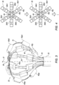
- FIG. 4 is a schematic illustration of a schema for wiring electrodes 40 during an IRE procedure, in accordance with some examples of the present disclosure.
- spines 36 typically comprise multiple half-spines 36h extending between tube 34 (e.g., via a coupling element) and the distal end of the probe.
- each spine is a half-spine, in that the spine does not define a loop, but rather, terminates at support element 50 ( Fig. 2 ).
- each spine comprises two half-spines continuous with one another at crossover 66.
- Fig. 4 shows a view of spines 36 from the distal end of the probe, and identifies six half-spines 36h1, 36h2, 36h3, 36h4, 36h5, and 36h6.
- each spine is shown in Fig. 4 as if the spine were decoupled from tube 34 ( Fig. 1 ) and laid flat on a surface.
- the offset between distal electrodes 40dd and 40dp, and the offset between proximal electrodes 40pd and 40pp, are ignored.
- the first subset of electrodes shorted to each other by wiring 45 are coupled to one or more adjacent first ones of the half-spines, and the second subset of electrodes shorted to each other are coupled to one or more adjacent second ones of the half-spines.
- the first subset is coupled to N/2 of the half-spines and the second subset is coupled to the other N/2 of the half-spines, N being the number of half-spines.
- the first subset which may be referred to as the "eastern” subset
- the second subset which may be referred to as the "western" subset.
- the first subset, each electrode of which is labeled by a "1,” may be coupled to half-spines 36h1, 36h2, and 36h3
- the second subset, each electrode of which is labeled by a "2” may be coupled to half-spines 36h4, 36h5, and 36h6.
- the shorting of the electrodes may be hardwired.
- processor 47 by controlling switches 45a ( Fig. 1 ), rotates the electrodes during the IRE procedure.
- the processor may cause the switches to connect the electrodes on half-spine 36h4 to the first subset, and the electrodes on half-spine 36h1 to the second subset, as shown at the lower portion of Fig. 4 . Subsequently, the voltage may be applied again. The processor may then continue iterating through the settings of the switches, causing the generator to apply a voltage in each of the settings.
- Table 1 shows a sequence of settings through which the processor may iterate (e.g., repeatedly).
- the entry in Table 1 corresponding to each half-spine and setting indicates the subset to which the electrodes on the half-spine belong per the setting.
- Setting 1 of Table 1 is shown at the upper portion of Fig. 4
- Setting 2 is shown at the lower portion of Fig. 4 .
- Table 1 Setting 1 Setting 2 Setting 3 Setting 4
- Setting 5 Setting 6 36h1 1 2 2 2 1 1 1 36h2 1 1 2 2 2 1 36h3 1 1 1 2 2 2 36h4 2 1 1 1 2 2 36h5 2 2 1 1 1 2 36h6 2 2 1 1 1 1
- FIG. 5 is a schematic illustration of another schema for wiring electrodes 40, in accordance with some examples of the present disclosure.
- the first subset of electrodes are shorted to those of the spines to which the first subset are coupled, and the second subset are shorted to those of the spines to which the second subset are coupled.
- the electrodes on each spine may be shorted to the superelastic element 46 ( Figs. 2-3 ) to which the electrodes are coupled. (The shorting of the electrodes to the spines is indicated in Fig. 5 by shorting symbols 68.)
- the first subset includes those of the electrodes coupled to M/2 (or (M+1)/2, for M odd) of the spines
- the second subset includes those of the electrodes coupled to the other M/2 (or (M-1)/2, for M odd) of the spines.
- processor 47 controls switches 45a ( Fig. 1 ) so as to vary the first and second subsets. For example, for an example with three spines, the processor may iterate (e.g., repeatedly) through the three settings shown in Fig. 5 .
- FIG. 6 is a schematic illustration of another schema for wiring electrodes 40, in accordance with some examples of the present disclosure.
- the first subset are distal to the second subset.
- the first subset may include distal electrodes 40d
- the second subset may include proximal electrodes 40p.
- the processor may iterate (e.g., repeatedly) through a sequence of settings from multiple different schemas. For example, following the six settings of Table 1, the processor may iterate through the three settings of Fig. 5 , and then the setting of Fig. 6 .
- FIG. 4-6 show the example of Fig. 3 by way of example, the shorting of electrodes as described herein may be implemented with any suitable probe, such as the example of Fig. 2 .
- An apparatus (22) including a tube (34), a support element (50), multiple spines (36) proximally coupled to the tube (34) and including respective expandable superelastic elements (46) and respective polymeric elements (48) extending from respective distal ends of the superelastic elements (46) and coupled to a surface (60) of the support element (50) by virtue of being bent proximally, into alignment with the surface (60), at a distal end of the support element (50), and multiple electrodes (40) coupled to the spines (36).
- the apparatus (22) according to any one of Examples 2-3, wherein the electrodes (40) are coupled to the sleeves (54), such that the sleeves (54) insulate the superelastic elements (46) from the electrodes (40).
- a method including deploying a probe from a sheath within a body of a subject, the probe including a tube, a support element, and multiple spines proximally coupled to the tube.
- the spines include respective expandable superelastic elements, and respective polymeric elements extending from respective distal ends of the superelastic elements and coupled to a surface of the support element by virtue of being bent proximally, into alignment with the surface, at a distal end of the support element.
- the method further includes, using multiple electrodes coupled to the spines, performing a procedure on the subject.
- An apparatus (22) including a tube (34) and multiple spines (36), each of the spines (36) having two ends coupled to the tube (34) opposite one another such that the spines (36) arc distally from the tube (34) and cross over each other at a crossover (66).
- the spines (36) include respective expandable superelastic elements (46) and respective sets of one or more polymeric sleeves (54) partially covering the superelastic elements (46) such that at least one of the superelastic elements (46) is uncovered at the crossover (66).
- the apparatus (22) further includes multiple electrodes (44) coupled to respective ones of the polymeric sleeves (54) .
- each of the superelastic elements (46) is covered by at least two of the polymeric sleeves (54) and is uncovered between the two of the polymeric sleeves (54).
- a method including deploying a probe from a sheath within a body of a subject, the probe including a tube and multiple spines.
- Each of the spines has two ends coupled to the tube opposite one another such that the spines arc distally from the tube and cross over each other at a crossover.
- the spines include respective expandable superelastic elements, and respective sets of one or more polymeric sleeves partially covering the superelastic elements such that at least one of the superelastic elements is uncovered at the crossover.
- the method further includes, using multiple electrodes coupled to respective ones of the polymeric sleeves, performing a procedure on the subject.
- the system (20) further includes a processor (47) configured to control the switches (45a) so as to alternate through the settings and, for each of the settings, cause a power generator (43) to apply a voltage between the shorted first subset and the shorted second subset while the probe (22) is deployed within a body of a subject (28).
- the spines (36) include multiple half-spines extending between a tube (34) and a distal end of the probe (22), and wherein, per at least one of the settings, the first subset of the electrodes (40) are coupled to one or more adjacent first ones of the half-spines, and the second subset of the electrodes (40) are coupled to one or more adjacent second ones of the half-spines.
- the system (20) according to any one of Examples 14-18, wherein, per at least one of the settings, the switches (45a) short the first subset to those of the spines (36) to which the first subset are coupled, and short the second subset to those of the spines (36) to which the second subset are coupled.
- a method for use with multiple electrodes coupled to respective spines of a probe including, by controlling multiple switches connected to the electrodes, causing the switches to short different respective first subsets of the electrodes to each other and different respective second subsets of the electrodes to each other per different respective settings of the switches.
- the method further includes, for each of the settings, causing a power generator to apply a voltage between the shorted first subset and the shorted second subset while the probe is deployed within a body of a subject.
- the instructions further cause the processor (47) to cause a power generator (43), for each of the settings, to apply a voltage between the shorted first subset and the shorted second subset while the probe (22) is deployed within a body of a subject (28) .
- the spines (36) include multiple half-spines extending between a tube (34) and a distal end of the probe (22), and wherein, per at least one of the settings, the first subset of the electrodes (40) are coupled to one or more adjacent first ones of the half-spines, and the second subset of the electrodes (40) are coupled to one or more adjacent second ones of the half-spines.
- a system for use with multiple electrodes coupled to respective spines of a probe including wiring connected to the electrodes and configured to short at least one first subset of the electrodes to each other and at least one second subset of the electrodes to each other while the probe is deployed within a body of a subject.
- the system further includes a power generator, configured to apply a voltage between the shorted first subset and the shorted second subset, the voltage having a constant positive amplitude for at least 100 ns and a constant negative amplitude for at least 100 ns.
Landscapes
- Health & Medical Sciences (AREA)
- Surgery (AREA)
- Engineering & Computer Science (AREA)
- Life Sciences & Earth Sciences (AREA)
- Medical Informatics (AREA)
- General Health & Medical Sciences (AREA)
- Nuclear Medicine, Radiotherapy & Molecular Imaging (AREA)
- Plasma & Fusion (AREA)
- Biomedical Technology (AREA)
- Heart & Thoracic Surgery (AREA)
- Physics & Mathematics (AREA)
- Molecular Biology (AREA)
- Animal Behavior & Ethology (AREA)
- Otolaryngology (AREA)
- Public Health (AREA)
- Veterinary Medicine (AREA)
- Cardiology (AREA)
- Measurement And Recording Of Electrical Phenomena And Electrical Characteristics Of The Living Body (AREA)
- Surgical Instruments (AREA)
- Electrodes For Compound Or Non-Metal Manufacture (AREA)
- Electrolytic Production Of Metals (AREA)
Applications Claiming Priority (1)
| Application Number | Priority Date | Filing Date | Title |
|---|---|---|---|
| US17/559,558 US12419683B2 (en) | 2021-12-22 | 2021-12-22 | Irreversible electroporation with shorted electrodes |
Publications (1)
| Publication Number | Publication Date |
|---|---|
| EP4201352A1 true EP4201352A1 (de) | 2023-06-28 |
Family
ID=84569315
Family Applications (1)
| Application Number | Title | Priority Date | Filing Date |
|---|---|---|---|
| EP22215386.8A Pending EP4201352A1 (de) | 2021-12-22 | 2022-12-21 | Irreversible elektroporation mit kurzgeschlossenen elektroden |
Country Status (5)
| Country | Link |
|---|---|
| US (2) | US12419683B2 (de) |
| EP (1) | EP4201352A1 (de) |
| JP (1) | JP2023093396A (de) |
| CN (1) | CN116370058A (de) |
| IL (1) | IL299226A (de) |
Cited By (1)
| Publication number | Priority date | Publication date | Assignee | Title |
|---|---|---|---|---|
| US12076071B2 (en) | 2020-08-14 | 2024-09-03 | Kardium Inc. | Systems and methods for treating tissue with pulsed field ablation |
Families Citing this family (3)
| Publication number | Priority date | Publication date | Assignee | Title |
|---|---|---|---|---|
| US20230301712A1 (en) * | 2022-03-25 | 2023-09-28 | Biosense Webster (Israel) Ltd. | Elongated trapezoidal electrodes of a basket catheter and methods of making the same |
| US12471988B2 (en) | 2022-12-07 | 2025-11-18 | Biosense Webster (Israel) Ltd. | Pulsed field ablation synchronization |
| US20240216046A1 (en) * | 2022-12-29 | 2024-07-04 | Biosense Webster (Israel) Ltd. | Systems and methods for linear spines forming a spherical basket for improved tissue contact and current delivery |
Citations (17)
| Publication number | Priority date | Publication date | Assignee | Title |
|---|---|---|---|---|
| US5391199A (en) | 1993-07-20 | 1995-02-21 | Biosense, Inc. | Apparatus and method for treating cardiac arrhythmias |
| US5558091A (en) | 1993-10-06 | 1996-09-24 | Biosense, Inc. | Magnetic determination of position and orientation |
| US5944022A (en) | 1997-04-28 | 1999-08-31 | American Cardiac Ablation Co. Inc. | Catheter positioning system |
| US5983126A (en) | 1995-11-22 | 1999-11-09 | Medtronic, Inc. | Catheter location system and method |
| WO2000066018A1 (en) * | 1999-05-04 | 2000-11-09 | Curon Medical, Inc. | Expandable electrode assemblies |
| US6177792B1 (en) | 1996-03-26 | 2001-01-23 | Bisense, Inc. | Mutual induction correction for radiator coils of an objects tracking system |
| US6690963B2 (en) | 1995-01-24 | 2004-02-10 | Biosense, Inc. | System for determining the location and orientation of an invasive medical instrument |
| US20060100669A1 (en) | 2001-12-31 | 2006-05-11 | Biosense Webster, Inc. | Method and system for atrial defibrillation |
| US7507234B2 (en) | 1996-10-11 | 2009-03-24 | BÂRRX Medical, Inc. | Method for cryogenic tissue ablation |
| US7536218B2 (en) | 2005-07-15 | 2009-05-19 | Biosense Webster, Inc. | Hybrid magnetic-based and impedance-based position sensing |
| US8456182B2 (en) | 2008-09-30 | 2013-06-04 | Biosense Webster, Inc. | Current localization tracker |
| US20170071544A1 (en) | 2015-09-14 | 2017-03-16 | Biosense Webster (Israel) Ltd. | Basket catheter with individual spine control |
| US20190069950A1 (en) * | 2017-07-06 | 2019-03-07 | Farapulse, Inc. | Systems, devices, and methods for focal ablation |
| US20190239811A1 (en) | 2011-12-30 | 2019-08-08 | St Jude Medical, Atrial Fibrillation Division, Inc | Electrode support structure assemblies |
| US20210137587A1 (en) * | 2017-04-10 | 2021-05-13 | St. Jude Medical, Cardiology Division, Inc. | Electroporation system and method of energizing a catheter |
| CN113100916A (zh) * | 2020-10-19 | 2021-07-13 | 伯恩森斯韦伯斯特(以色列)有限责任公司 | 使用单极配置用于不可逆电穿孔(ire) |
| EP3960105A1 (de) * | 2020-08-13 | 2022-03-02 | Biosense Webster (Israel) Ltd | Anwendung von bipolarer ablationsenergie zwischen kurzgeschlossenen elektrodengruppen |
Family Cites Families (274)
| Publication number | Priority date | Publication date | Assignee | Title |
|---|---|---|---|---|
| US5904680A (en) | 1992-09-25 | 1999-05-18 | Ep Technologies, Inc. | Multiple electrode support structures having optimal bio-mechanical characteristics |
| US6014590A (en) | 1974-03-04 | 2000-01-11 | Ep Technologies, Inc. | Systems and methods employing structures having asymmetric mechanical properties to support diagnostic or therapeutic elements in contact with tissue in interior body regions |
| US4699147A (en) | 1985-09-25 | 1987-10-13 | Cordis Corporation | Intraventricular multielectrode cardial mapping probe and method for using same |
| US5215103A (en) | 1986-11-14 | 1993-06-01 | Desai Jawahar M | Catheter for mapping and ablation and method therefor |
| US5365926A (en) | 1986-11-14 | 1994-11-22 | Desai Jawahar M | Catheter for mapping and ablation and method therefor |
| US4940064A (en) | 1986-11-14 | 1990-07-10 | Desai Jawahar M | Catheter for mapping and ablation and method therefor |
| US5465717A (en) | 1991-02-15 | 1995-11-14 | Cardiac Pathways Corporation | Apparatus and Method for ventricular mapping and ablation |
| US5345936A (en) | 1991-02-15 | 1994-09-13 | Cardiac Pathways Corporation | Apparatus with basket assembly for endocardial mapping |
| US5456254A (en) | 1991-02-15 | 1995-10-10 | Cardiac Pathways Corp | Flexible strip assembly having insulating layer with conductive pads exposed through insulating layer and device utilizing the same |
| US5415166A (en) | 1991-02-15 | 1995-05-16 | Cardiac Pathways Corporation | Endocardial mapping apparatus and cylindrical semiconductor device mounting structure for use therewith and method |
| US5383917A (en) | 1991-07-05 | 1995-01-24 | Jawahar M. Desai | Device and method for multi-phase radio-frequency ablation |
| US5255679A (en) | 1992-06-02 | 1993-10-26 | Cardiac Pathways Corporation | Endocardial catheter for mapping and/or ablation with an expandable basket structure having means for providing selective reinforcement and pressure sensing mechanism for use therewith, and method |
| US5324284A (en) | 1992-06-05 | 1994-06-28 | Cardiac Pathways, Inc. | Endocardial mapping and ablation system utilizing a separately controlled ablation catheter and method |
| US5772590A (en) | 1992-06-30 | 1998-06-30 | Cordis Webster, Inc. | Cardiovascular catheter with laterally stable basket-shaped electrode array with puller wire |
| US5411025A (en) | 1992-06-30 | 1995-05-02 | Cordis Webster, Inc. | Cardiovascular catheter with laterally stable basket-shaped electrode array |
| US5782239A (en) | 1992-06-30 | 1998-07-21 | Cordis Webster, Inc. | Unique electrode configurations for cardiovascular electrode catheter with built-in deflection method and central puller wire |
| US7189208B1 (en) | 1992-09-23 | 2007-03-13 | Endocardial Solutions, Inc. | Method for measuring heart electrophysiology |
| US6240307B1 (en) | 1993-09-23 | 2001-05-29 | Endocardial Solutions, Inc. | Endocardial mapping system |
| US5549108A (en) | 1992-09-25 | 1996-08-27 | Ep Technologies, Inc. | Cardiac mapping and ablation systems |
| US5313943A (en) | 1992-09-25 | 1994-05-24 | Ep Technologies, Inc. | Catheters and methods for performing cardiac diagnosis and treatment |
| US5293869A (en) | 1992-09-25 | 1994-03-15 | Ep Technologies, Inc. | Cardiac probe with dynamic support for maintaining constant surface contact during heart systole and diastole |
| EP0668740A4 (de) | 1992-09-25 | 1998-10-07 | Ep Technologies | Streifenförmiger träger für elektroden zur diagnostik und therapie von herzbeschwerden. |
| US5309910A (en) | 1992-09-25 | 1994-05-10 | Ep Technologies, Inc. | Cardiac mapping and ablation systems |
| WO1994021169A1 (en) | 1993-03-16 | 1994-09-29 | Ep Technologies, Inc. | Flexible interlaced multiple electrode assemblies |
| US5893847A (en) | 1993-03-16 | 1999-04-13 | Ep Technologies, Inc. | Multiple electrode support structures with slotted hub and hoop spline elements |
| US5823189A (en) | 1993-03-16 | 1998-10-20 | Ep Technologies, Inc. | Multiple electrode support structures with spline elements and over-molded hub |
| US5725525A (en) | 1993-03-16 | 1998-03-10 | Ep Technologies, Inc. | Multiple electrode support structures with integral hub and spline elements |
| WO1994021170A1 (en) | 1993-03-16 | 1994-09-29 | Ep Technologies, Inc. | Flexible circuit assemblies employing ribbon cable |
| US5476495A (en) | 1993-03-16 | 1995-12-19 | Ep Technologies, Inc. | Cardiac mapping and ablation systems |
| AU676559B2 (en) | 1993-04-07 | 1997-03-13 | Cardiac Pathways Corporation | Apparatus and method for ventricular mapping |
| IL116699A (en) | 1996-01-08 | 2001-09-13 | Biosense Ltd | Method of building a heart map |
| US5396887A (en) | 1993-09-23 | 1995-03-14 | Cardiac Pathways Corporation | Apparatus and method for detecting contact pressure |
| US5526810A (en) | 1993-10-07 | 1996-06-18 | Wang; Dai-Yuen | Intraventricular mapping catheter |
| US5400783A (en) | 1993-10-12 | 1995-03-28 | Cardiac Pathways Corporation | Endocardial mapping apparatus with rotatable arm and method |
| US5881727A (en) | 1993-10-14 | 1999-03-16 | Ep Technologies, Inc. | Integrated cardiac mapping and ablation probe |
| WO1995010320A1 (en) | 1993-10-15 | 1995-04-20 | Ep Technologies, Inc. | Device for lengthening cardiac conduction pathways |
| WO1995020348A1 (en) | 1994-01-28 | 1995-08-03 | Ep Technologies, Inc. | Matching electrical characteristics and propagation velocities to locate ablation sites |
| US5577509A (en) | 1994-01-28 | 1996-11-26 | Ep Technologies, Inc. | Systems and methods for examining the electrical characteristics and timing of electrical events in cardiac tissue |
| US5911739A (en) | 1994-03-04 | 1999-06-15 | Ep Technologies, Inc. | Structures for supporting diagnostic or therapeutic elements in internal body regions |
| US5968040A (en) | 1994-03-04 | 1999-10-19 | Ep Technologies, Inc. | Systems and methods using asymmetric multiple electrode arrays |
| US6216043B1 (en) | 1994-03-04 | 2001-04-10 | Ep Technologies, Inc. | Asymmetric multiple electrode support structures |
| US5598848A (en) | 1994-03-31 | 1997-02-04 | Ep Technologies, Inc. | Systems and methods for positioning multiple electrode structures in electrical contact with the myocardium |
| US5876336A (en) | 1994-10-11 | 1999-03-02 | Ep Technologies, Inc. | Systems and methods for guiding movable electrode elements within multiple-electrode structure |
| US5722401A (en) | 1994-10-19 | 1998-03-03 | Cardiac Pathways Corporation | Endocardial mapping and/or ablation catheter probe |
| IT1278369B1 (it) | 1995-02-14 | 1997-11-20 | Sorin Biomedica Cardio Spa | Catetere, particolarmente per il trattamento di aritmie cardiache. |
| IT1278372B1 (it) | 1995-02-15 | 1997-11-20 | Sorin Biomedica Cardio Spa | Catetere, particolarmente per il trattamento di aritmie cardiache. |
| US5595183A (en) | 1995-02-17 | 1997-01-21 | Ep Technologies, Inc. | Systems and methods for examining heart tissue employing multiple electrode structures and roving electrodes |
| US5609157A (en) | 1995-02-17 | 1997-03-11 | Ep Technologies, Inc. | Systems and methods for analyzing biopotential morphologies in body tissue using iterative techniques |
| JP3681126B2 (ja) | 1995-02-17 | 2005-08-10 | ボストン サイエンティフィック リミテッド | 生物学的事象の時系列計測を行うためのシステム |
| WO1996034560A1 (en) | 1995-05-02 | 1996-11-07 | Heart Rhythm Technologies, Inc. | Catheter with expandable probe |
| US5681280A (en) | 1995-05-02 | 1997-10-28 | Heart Rhythm Technologies, Inc. | Catheter control system |
| US5722403A (en) | 1996-10-28 | 1998-03-03 | Ep Technologies, Inc. | Systems and methods using a porous electrode for ablating and visualizing interior tissue regions |
| US6014579A (en) | 1997-07-21 | 2000-01-11 | Cardiac Pathways Corp. | Endocardial mapping catheter with movable electrode |
| US6428537B1 (en) | 1998-05-22 | 2002-08-06 | Scimed Life Systems, Inc. | Electrophysiological treatment methods and apparatus employing high voltage pulse to render tissue temporarily unresponsive |
| US6119030A (en) | 1998-06-22 | 2000-09-12 | Ep Technologies, Inc. | Silicone tip for multiple electrode basket assemblies |
| DE60032751T2 (de) | 1999-04-05 | 2007-11-08 | The Regents Of The University Of California, Oakland | Endomyokardiale einphasige aktionspotentiale zum frühnachweis der myokardium pathologie |
| US6892091B1 (en) | 2000-02-18 | 2005-05-10 | Biosense, Inc. | Catheter, method and apparatus for generating an electrical map of a chamber of the heart |
| DE60138319D1 (de) | 2000-05-03 | 2009-05-20 | Bard Inc C R | Gerät zur Darstellung und Ablation bei elektrophysiologischen Verfahren |
| US6584345B2 (en) | 2001-03-13 | 2003-06-24 | Biosense, Inc. | Apparatus and method for measuring a plurality of electrical signals from the body of a patient |
| DE60230499D1 (de) | 2001-04-27 | 2009-02-05 | Bard Inc C R | Katheter zur drei-dimensionallen abbildung der elektrischen aktivität in blutgefässen |
| US6748255B2 (en) | 2001-12-14 | 2004-06-08 | Biosense Webster, Inc. | Basket catheter with multiple location sensors |
| US6741878B2 (en) | 2001-12-14 | 2004-05-25 | Biosense Webster, Inc. | Basket catheter with improved expansion mechanism |
| EP1487366B1 (de) | 2002-03-15 | 2007-08-08 | C.R. Bard, Inc. | Apparat zur steuerung von ablationsenergie und elektrogrammaufnahme mittels einer vielzahl gemeinsamer elektroden in einem elektrophysiologie-katheter |
| US6866662B2 (en) | 2002-07-23 | 2005-03-15 | Biosense Webster, Inc. | Ablation catheter having stabilizing array |
| US6780183B2 (en) | 2002-09-16 | 2004-08-24 | Biosense Webster, Inc. | Ablation catheter having shape-changing balloon |
| US7722604B2 (en) | 2003-03-28 | 2010-05-25 | C.R. Bard, Inc. | Braided mesh catheter |
| ES2400508T3 (es) | 2003-07-11 | 2013-04-10 | S.D.M.H. Pty. Ltd. | Ablación térmica de tejido biológico |
| US8007495B2 (en) | 2004-03-31 | 2011-08-30 | Biosense Webster, Inc. | Catheter for circumferential ablation at or near a pulmonary vein |
| US8048063B2 (en) | 2006-06-09 | 2011-11-01 | Endosense Sa | Catheter having tri-axial force sensor |
| US8567265B2 (en) | 2006-06-09 | 2013-10-29 | Endosense, SA | Triaxial fiber optic force sensing catheter |
| US7729752B2 (en) | 2006-06-13 | 2010-06-01 | Rhythmia Medical, Inc. | Non-contact cardiac mapping, including resolution map |
| US7515954B2 (en) | 2006-06-13 | 2009-04-07 | Rhythmia Medical, Inc. | Non-contact cardiac mapping, including moving catheter and multi-beat integration |
| US8517999B2 (en) | 2007-04-04 | 2013-08-27 | St. Jude Medical, Atrial Fibrillation Division, Inc. | Irrigated catheter with improved fluid flow |
| WO2008141150A2 (en) | 2007-05-09 | 2008-11-20 | Irvine Biomedical, Inc. | Basket catheter having multiple electrodes |
| US8906011B2 (en) | 2007-11-16 | 2014-12-09 | Kardium Inc. | Medical device for use in bodily lumens, for example an atrium |
| CN101888813B (zh) | 2007-12-06 | 2012-12-12 | 皇家飞利浦电子股份有限公司 | 用于将能量施加到对象的设备、方法和计算机程序 |
| US8103327B2 (en) | 2007-12-28 | 2012-01-24 | Rhythmia Medical, Inc. | Cardiac mapping catheter |
| WO2009094588A2 (en) | 2008-01-24 | 2009-07-30 | Coherex Medical, Inc. | Systems and methods for reduction of atrial fibrillation |
| JP5646492B2 (ja) | 2008-10-07 | 2014-12-24 | エムシー10 インコーポレイテッドMc10,Inc. | 伸縮可能な集積回路およびセンサアレイを有する装置 |
| US9339331B2 (en) | 2008-12-29 | 2016-05-17 | St. Jude Medical, Atrial Fibrillation Division, Inc. | Non-contact electrode basket catheters with irrigation |
| US8712550B2 (en) | 2008-12-30 | 2014-04-29 | Biosense Webster, Inc. | Catheter with multiple electrode assemblies for use at or near tubular regions of the heart |
| US8167845B2 (en) | 2009-06-02 | 2012-05-01 | St. Jude Medical, Atrial Fibrillation Division, Inc. | Catheter having distal sealing member |
| CA2781951A1 (en) | 2009-11-13 | 2011-05-19 | St. Jude Medical, Inc. | Assembly of staggered ablation elements |
| US20110245756A1 (en) | 2009-12-03 | 2011-10-06 | Rishi Arora | Devices for material delivery, electroporation, sonoporation, and/or monitoring electrophysiological activity |
| US8560086B2 (en) | 2010-12-02 | 2013-10-15 | St. Jude Medical, Atrial Fibrillation Division, Inc. | Catheter electrode assemblies and methods of construction therefor |
| CA2764494A1 (en) | 2011-01-21 | 2012-07-21 | Kardium Inc. | Enhanced medical device for use in bodily cavities, for example an atrium |
| US9486273B2 (en) | 2011-01-21 | 2016-11-08 | Kardium Inc. | High-density electrode-based medical device system |
| WO2012145073A1 (en) | 2011-04-22 | 2012-10-26 | Topera, Inc. | Basket style cardiac mapping catheter having spline bends for detection of cardiac rhythm disorders |
| US20130030430A1 (en) | 2011-07-29 | 2013-01-31 | Stewart Mark T | Intracardiac tools and methods for delivery of electroporation therapies |
| US9277960B2 (en) | 2011-09-08 | 2016-03-08 | Kardium Inc. | Intra-cardiac mapping and ablating |
| US8498686B2 (en) | 2011-10-04 | 2013-07-30 | Biosense Webster (Israel), Ltd. | Mapping catheter with spiral electrode assembly |
| US9265459B2 (en) | 2011-10-07 | 2016-02-23 | Boston Scientific Scimed, Inc. | Methods and systems for detection and thermal treatment of lower urinary tract conditions |
| JP5729660B2 (ja) | 2011-11-21 | 2015-06-03 | 株式会社ディナーヴ | 腎動脈アブレーション用のカテーテルおよびシステム |
| US9131980B2 (en) | 2011-12-19 | 2015-09-15 | Medtronic Advanced Energy Llc | Electrosurgical devices |
| WO2013101452A1 (en) | 2011-12-28 | 2013-07-04 | Boston Scientific Scimed, Inc. | Device and methods for nerve modulation using a novel ablation catheter with polymeric ablative elements |
| US20130231659A1 (en) | 2012-03-01 | 2013-09-05 | Boston Scientific Scimed, Inc. | Off-wall and contact electrode devices and methods for nerve modulation |
| EP2840996B1 (de) | 2012-04-26 | 2019-03-20 | Medtronic Ablation Frontiers LLC | System zum nachweis von gewebekontakten während einer ablation |
| US9883908B2 (en) | 2012-05-02 | 2018-02-06 | The Charlotte-Mecklenburg Hospital Authority | Devices, systems, and methods for treating cardiac arrhythmias |
| US9017321B2 (en) | 2012-05-21 | 2015-04-28 | Kardium, Inc. | Systems and methods for activating transducers |
| WO2014015065A1 (en) | 2012-07-17 | 2014-01-23 | Boston Scientific Scimed, Inc. | Renal nerve modulation catheter design |
| US10314649B2 (en) | 2012-08-02 | 2019-06-11 | Ethicon Endo-Surgery, Inc. | Flexible expandable electrode and method of intraluminal delivery of pulsed power |
| US9801681B2 (en) | 2012-08-17 | 2017-10-31 | Medtronic Ablation Frontiers Llc | Catheters and methods for intracardiac electrical mapping |
| EP2890292B1 (de) | 2012-08-31 | 2021-01-13 | Acutus Medical, Inc. | Kathetersystem für das herz |
| US20140180147A1 (en) | 2012-12-20 | 2014-06-26 | Boston Scientific Scimed, Inc. | Estimating interspline distances on mapping catheters |
| CN104869889B (zh) | 2012-12-20 | 2017-10-10 | 波士顿科学医学有限公司 | 用于映射期间的电极接触的实时反馈 |
| US9681817B2 (en) | 2012-12-20 | 2017-06-20 | Boston Scientific Scimed, Inc. | Suppression of global activation signals during anatomical mapping |
| EP3777703B1 (de) | 2013-02-08 | 2023-04-05 | Acutus Medical Inc. | Expandierbare katheteranordnung mit einer flexiblen leiterplatte |
| US9474486B2 (en) | 2013-03-08 | 2016-10-25 | St. Jude Medical, Atrial Fibrillation Division, Inc. | Basket for a multi-electrode array catheter |
| US10792089B2 (en) | 2013-03-13 | 2020-10-06 | Kardium, Inc. | Detecting improper energy transmission configuration in medical device system |
| US9345540B2 (en) | 2013-03-15 | 2016-05-24 | Medtronic Ablation Frontiers Llc | Contact specific RF therapy balloon |
| US10575743B2 (en) | 2013-04-11 | 2020-03-03 | Biosense Webster (Israel) Ltd. | High electrode density basket catheter |
| US10602947B2 (en) | 2013-04-11 | 2020-03-31 | Biosense Webster (Israel), Ltd. | High density electrode structure |
| EP2988691B1 (de) | 2013-04-25 | 2018-03-28 | St. Jude Medical, Cardiology Division, Inc. | Elektrodenanordnung für kathetersystem |
| WO2014195933A1 (en) | 2013-06-05 | 2014-12-11 | Tel Hashomer Medical Research Infrastructure And Services Ltd. | Myocardial ablation by irreversible electroporation |
| US9814618B2 (en) | 2013-06-06 | 2017-11-14 | Boston Scientific Scimed, Inc. | Devices for delivering energy and related methods of use |
| US20150011991A1 (en) | 2013-07-03 | 2015-01-08 | St. Jude Medical, Cardiology Division, Inc. | Electrode Assembly For Catheter System |
| US20150045863A1 (en) | 2013-08-07 | 2015-02-12 | Boston Scientific Scimed, Inc. | Expandable electrodes and methods for treating tissues |
| US9204929B2 (en) | 2013-09-16 | 2015-12-08 | Biosense Webster (Israel) Ltd. | Basket catheter with deflectable spine |
| US10687889B2 (en) | 2013-10-11 | 2020-06-23 | Biosense Webster (Israel) Ltd. | Patient-specific pre-shaped cardiac catheter |
| US20150119878A1 (en) | 2013-10-24 | 2015-04-30 | St. Jude Medical, Cardiology Division, Inc. | Electrode assembly having asymmetric electrode placement |
| EP3043735A1 (de) | 2013-11-07 | 2016-07-20 | St. Jude Medical, Cardiology Division, Inc. | Medizinische vorrichtung mit kontaktstärkemessspitze |
| WO2015077816A1 (en) | 2013-11-29 | 2015-06-04 | Cathrx Ltd | A basket catheter and method of manufacturing |
| US10314648B2 (en) | 2013-12-13 | 2019-06-11 | The Trustees of the Universoty of Pennsylvania | Coaxial ablation probe and method and system for real-time monitoring of ablation therapy |
| US9993160B2 (en) | 2014-01-07 | 2018-06-12 | Kardium Inc. | Medical device including manipulable portion with connected elongate members |
| US9554718B2 (en) | 2014-01-29 | 2017-01-31 | Biosense Webster (Israel) Ltd. | Double bipolar configuration for atrial fibrillation annotation |
| EP3424453B1 (de) | 2014-02-04 | 2026-04-01 | Boston Scientific Scimed, Inc. | Alternative platzierung von thermischen sensoren auf bipolarer elektrode |
| EP3073907B1 (de) | 2014-02-25 | 2020-06-17 | St. Jude Medical, Cardiology Division, Inc. | System zur lokalen elektrophysiologischen charakterisierung eines kardialen substrats mit mehrfachelektrodenkathetern |
| US9986949B2 (en) | 2014-03-05 | 2018-06-05 | Biosense Webster (Israel) Ltd. | Multi-arm catheter with signal transmission over braid wires |
| WO2015134248A1 (en) | 2014-03-06 | 2015-09-11 | Boston Scientific Scimed, Inc. | Medical devices for mapping cardiac tissue and methods for displaying mapping data |
| US20150270634A1 (en) | 2014-03-21 | 2015-09-24 | St. Jude Medical, Cardiology Division, Inc. | Electrode assembly for catheter system including struts having a non-uniform thickness |
| CN106255451B (zh) | 2014-05-06 | 2020-03-17 | 圣犹达医疗用品心脏病学部门有限公司 | 电极支撑结构组件 |
| WO2015187386A1 (en) | 2014-06-03 | 2015-12-10 | Boston Scientific Scimed, Inc. | Electrode assembly having an atraumatic distal tip |
| CN104257427A (zh) | 2014-08-05 | 2015-01-07 | 上海魅丽纬叶医疗科技有限公司 | 具有瓣状支架结构的射频消融导管及其设备 |
| EP3191164A4 (de) | 2014-09-12 | 2018-08-15 | X-Rhythm, LLC | Mehrelektrodenabbildungssystem |
| US20170296084A1 (en) | 2014-09-18 | 2017-10-19 | University Of Utah Research Foundation | Cardiac mapping catheter |
| US9314208B1 (en) | 2014-10-28 | 2016-04-19 | Biosense Webster (Israel) Ltd. | Basket catheter with microelectrode array distal tip |
| WO2016065464A1 (en) | 2014-10-30 | 2016-05-06 | Kardium Inc. | Catheter system |
| US9782099B2 (en) | 2014-12-31 | 2017-10-10 | Biosense Webster (Israel) Ltd. | Basket catheter with improved spine flexibility |
| US9833161B2 (en) | 2015-02-09 | 2017-12-05 | Biosense Webster (Israel) Ltd. | Basket catheter with far-field electrode |
| EP3282991A1 (de) | 2015-04-17 | 2018-02-21 | Boston Scientific Scimed Inc. | Gewebediagnose und -behandlung mithilfe von elektroden und mini-elektroden |
| US20160338770A1 (en) | 2015-05-19 | 2016-11-24 | Biosense Webster (Israel) Ltd. | Woven foldable catheter |
| US9895073B2 (en) | 2015-07-29 | 2018-02-20 | Biosense Webster (Israel) Ltd. | Dual basket catheter |
| US10492857B2 (en) | 2015-08-06 | 2019-12-03 | Boston Scientific Scimed Inc | Deployment control apparatus for a catheter with a deployable array |
| EP3331467A4 (de) | 2015-08-06 | 2019-01-23 | Apama Medical, Inc. | Multifunktionselektrode |
| US10376170B2 (en) | 2015-08-10 | 2019-08-13 | Boston Scientific Scimed, Inc. | Catheter with annular lumen to provide distal flushing |
| US20170071543A1 (en) | 2015-09-14 | 2017-03-16 | Biosense Webster (Israel) Ltd. | Convertible basket catheter |
| US10130420B2 (en) | 2015-10-08 | 2018-11-20 | Biosense Webster (Israel) Ltd. | Catheter with membraned spines for pulmonary vein isolation |
| CN108882884B (zh) | 2015-10-21 | 2022-05-31 | 奥托诺米克斯医药有限公司 | 心脏组织的受控和精确治疗 |
| US10758304B2 (en) | 2015-12-07 | 2020-09-01 | Biosense Webster (Israel) Ltd. | Basket catheter with an improved seal |
| US9894756B2 (en) | 2015-12-08 | 2018-02-13 | Kardium Inc. | Circuits for flexible structures |
| US10078713B2 (en) | 2015-12-24 | 2018-09-18 | Biosense Webster (Israel) Ltd. | Global mapping catheter contact optimization |
| US10660702B2 (en) | 2016-01-05 | 2020-05-26 | Farapulse, Inc. | Systems, devices, and methods for focal ablation |
| WO2019143960A1 (en) | 2018-01-18 | 2019-07-25 | Farapulse, Inc. | Systems, devices, and methods for focal ablation |
| US10172673B2 (en) | 2016-01-05 | 2019-01-08 | Farapulse, Inc. | Systems devices, and methods for delivery of pulsed electric field ablative energy to endocardial tissue |
| US10582894B2 (en) | 2016-01-14 | 2020-03-10 | Biosense Webster (Israel) Ltd. | Region of interest rotational activity pattern detection |
| US10314505B2 (en) | 2016-03-15 | 2019-06-11 | Biosense Webster (Israel) Ltd. | Asymmetric basket catheter |
| US10136828B2 (en) | 2016-03-31 | 2018-11-27 | Biosense Webster (Israel) Ltd. | Mapping of atrial fibrillation |
| US10362991B2 (en) | 2016-04-04 | 2019-07-30 | Biosense Webster (Israel) Ltd. | Convertible basket catheter |
| US20170296251A1 (en) | 2016-04-13 | 2017-10-19 | Biosense Webster (Israel) Ltd. | Basket catheter with prestrained framework |
| US20170296260A1 (en) | 2016-04-15 | 2017-10-19 | Cook Medical Technologies Llc | Ablation medical device with basket |
| US10105179B2 (en) | 2016-05-02 | 2018-10-23 | Affera, Inc. | Catheter sensing and irrigating |
| US9974460B2 (en) | 2016-05-06 | 2018-05-22 | Biosense Webster (Israel) Ltd. | Basket-shaped catheter with improved distal hub |
| US10537260B2 (en) | 2016-05-06 | 2020-01-21 | Biosense Webster (Israel) Ltd. | Varying diameter catheter distal end design for decreased distal hub size |
| US10772566B2 (en) | 2016-05-17 | 2020-09-15 | Biosense Weber (Israel) Ltd. | Multi-electrode catheter spine and method of making the same |
| US10898139B2 (en) | 2016-06-03 | 2021-01-26 | Biosense Webster (Israel) Ltd. | Spine construction for basket catheter |
| US20170354338A1 (en) | 2016-06-09 | 2017-12-14 | Biosense Webster (Israel) Ltd. | Dual-function sensors for a basket catheter |
| US10905329B2 (en) | 2016-06-09 | 2021-02-02 | Biosense Webster (Israel) Ltd. | Multi-function conducting elements for a catheter |
| US10349855B2 (en) | 2016-06-10 | 2019-07-16 | Biosense Webster (Israel) Ltd. | Identification and visualization of cardiac activation sequence in multi-channel recordings |
| WO2017223264A1 (en) * | 2016-06-23 | 2017-12-28 | St. Jude Medical, Cardiology Division, Inc. | Catheter system and electrode assembly for intraprocedural evaluation of renal denervation |
| US10376221B2 (en) | 2016-07-06 | 2019-08-13 | Biosense Webster (Israel) Ltd. | Automatic creation of multiple electroanatomic maps |
| JP7075922B2 (ja) | 2016-07-11 | 2022-05-26 | レトロバスキュラー インコーポレイテッド | 双極型組織切除装置及びその使用方法 |
| US20180085064A1 (en) | 2016-09-29 | 2018-03-29 | Biosense Webster (Israel) Ltd. | Basket catheter conforming to organ using strain-relief elements |
| US10314507B2 (en) | 2016-11-14 | 2019-06-11 | Biosense Webster (Israel) Ltd. | ASIC with switching noise reduction |
| US10403053B2 (en) | 2016-11-15 | 2019-09-03 | Biosense Webster (Israel) Ltd. | Marking sparse areas on maps |
| US11129574B2 (en) | 2016-12-12 | 2021-09-28 | Biosense Webster (Israel) Ltd. | Real time electroanatomical coloring of the heart |
| US10918306B2 (en) | 2016-12-13 | 2021-02-16 | Biosense Webster (Israel) Ltd. | Catheter splines with embedded circuit elements |
| US12414814B2 (en) | 2016-12-15 | 2025-09-16 | St. Jude Medical, Cardiology Division, Inc. | Pulmonary vein isolation balloon catheter |
| CN110087572A (zh) | 2016-12-19 | 2019-08-02 | 波士顿科学医学有限公司 | 带有纵向安装的花键的面向远端的电极阵列 |
| US20180184982A1 (en) | 2017-01-05 | 2018-07-05 | Biosense Webster (Israel) Ltd. | Hybrid balloon basket catheter |
| JP7033142B2 (ja) | 2017-01-06 | 2022-03-09 | セント・ジュード・メディカル,カーディオロジー・ディヴィジョン,インコーポレイテッド | 肺静脈隔離バルーンカテーテル |
| US20180192958A1 (en) | 2017-01-06 | 2018-07-12 | Biosense Webster (Israel) Ltd. | Multi-electrode assembly with controlled folding mechanism |
| US11246534B2 (en) | 2017-01-23 | 2022-02-15 | Biosense Webster (Israel) Ltd. | Basket catheter made from flexible circuit board with mechanical strengthening |
| EP3576612A4 (de) | 2017-02-01 | 2020-12-23 | The George Washington University | Hochauflösende multifunktions- und konforme elektronikvorrichtung zur diagnose und behandlung von herzarrhythmien |
| DE102017001971A1 (de) | 2017-03-01 | 2018-09-06 | Peter Osypka Stiftung Stiftung des bürgerlichen Rechts | Multi-Elektrodenanordnung |
| US11116450B2 (en) | 2017-03-09 | 2021-09-14 | Biosense Webster (Israel) Ltd. | Electrode assembly having spines with controlled flexibility |
| US10014607B1 (en) | 2017-03-13 | 2018-07-03 | Bionsense Webster (Israel) Ltd. | PCB sub-connectors |
| US10765371B2 (en) | 2017-03-31 | 2020-09-08 | Biosense Webster (Israel) Ltd. | Method to project a two dimensional image/photo onto a 3D reconstruction, such as an epicardial view of heart |
| WO2018187856A1 (en) | 2017-04-12 | 2018-10-18 | Kardium Inc. | Medical device systems and methods including helically configured or twisted, non-helically configured elongate members |
| US20180310987A1 (en) | 2017-04-27 | 2018-11-01 | Biosense Webster (Israel) Ltd. | Systems and processes for map-guided automatic cardiac ablation |
| US10617867B2 (en) | 2017-04-28 | 2020-04-14 | Farapulse, Inc. | Systems, devices, and methods for delivery of pulsed electric field ablative energy to esophageal tissue |
| US12029545B2 (en) | 2017-05-30 | 2024-07-09 | Biosense Webster (Israel) Ltd. | Catheter splines as location sensors |
| WO2018226761A1 (en) | 2017-06-06 | 2018-12-13 | Cardiac Pacemakers, Inc. | Ablation delivery using a catheter having a semi-permeable inflatable balloon structure |
| US20180360534A1 (en) | 2017-06-19 | 2018-12-20 | St. Jude Medical, Cardiology Division, Inc. | Apparatuses and methods for high-density sensing and ablation during a medical procedure |
| US10952795B2 (en) | 2017-06-30 | 2021-03-23 | Biosense Webster (Israel) Ltd. | System and method for glass state view in real-time three-dimensional (3D) cardiac imaging |
| US11666379B2 (en) | 2017-07-06 | 2023-06-06 | Biosense Webster (Israel) Ltd. | Temperature controlled short duration ablation with multiple electrodes |
| US11109788B2 (en) | 2017-07-17 | 2021-09-07 | Biosense Webster (Israel) Ltd. | Catheter with Fibonacci distributed electrodes |
| US11052246B2 (en) | 2017-07-28 | 2021-07-06 | Medtronic, Inc. | Expandable elements for delivery of electric fields |
| US11304603B2 (en) | 2017-08-21 | 2022-04-19 | Biosense Webster (Israel) Ltd. | Advanced current location (ACL) automatic map rotation to detect holes in current position map (CPM) mapping |
| US10682181B2 (en) | 2017-09-06 | 2020-06-16 | Biosense Webster (Israel) Ltd. | Methods and systems for modeling and registration of 3-dimensional images of the heart |
| CN115844523A (zh) | 2017-09-12 | 2023-03-28 | 波士顿科学医学有限公司 | 用于心室局灶性消融的系统、设备和方法 |
| US10441188B2 (en) | 2017-09-12 | 2019-10-15 | Biosense Webster (Israel) Ltd. | Automatic display of earliest LAT point |
| US10702178B2 (en) | 2017-10-13 | 2020-07-07 | St. Jude Medical, Cardiology Division, Inc. | Catheter with high-density mapping electrodes |
| EP3694432B1 (de) | 2017-10-13 | 2024-05-01 | Mayo Foundation for Medical Education and Research | Vorrichtungen zur elektroporation zur behandlung von kammerflimmern |
| US10398348B2 (en) | 2017-10-19 | 2019-09-03 | Biosense Webster (Israel) Ltd. | Baseline impedance maps for tissue proximity indications |
| US10959784B2 (en) | 2017-10-24 | 2021-03-30 | Biosense Webster (Israel) Ltd. | Determining balloon catheter contact with anatomy using ultrasound |
| EP4279004B1 (de) | 2017-10-26 | 2025-08-13 | Boston Scientific Scimed, Inc. | Verwendung von elektromagnetischen feldern bei der abgabe einer ire-vorrichtung und therapieüberwachung |
| WO2019084442A1 (en) | 2017-10-27 | 2019-05-02 | St. Jude Medical, Cardiology Division, Inc. | PULMONARY VEIN ISOLATION BALLOON CATHETER |
| US10881376B2 (en) | 2017-11-08 | 2021-01-05 | Biosense Webster (Israel) Ltd. | System and method for providing auditory guidance in medical systems |
| US11295835B2 (en) | 2017-11-27 | 2022-04-05 | Biosense Webster (Israel) Ltd. | System and method for interactive event timeline |
| US11164371B2 (en) | 2017-12-20 | 2021-11-02 | Biosense Webster (Israel) Ltd. | Marking a computerized model of a cardiac surface |
| DK3731771T3 (da) | 2017-12-26 | 2023-08-28 | Galvanize Therapeutics Inc | V462033dk00 |
| US11517715B2 (en) | 2018-01-02 | 2022-12-06 | Biosense Webster (Israel) Ltd. | Deflectable medical probe |
| US10973461B2 (en) | 2018-01-10 | 2021-04-13 | Biosense Webster (Israel) Ltd. | Mapping of intra-body cavity using a distributed ultrasound array on basket catheter |
| US11147496B2 (en) | 2018-01-16 | 2021-10-19 | Boston Scientific Scimed Inc. | Systems and methods for mapping electrical activity in the heart |
| US20190216347A1 (en) | 2018-01-16 | 2019-07-18 | Boston Scientific Scimed Inc. | Systems and methods for activation mapping of the heart without the use of a reference catheter |
| US20190314083A1 (en) | 2018-04-11 | 2019-10-17 | Biosense Webster (Israel) Ltd. | Flexible Multi-Arm Catheter with Diametrically Opposed Sensing Electrodes |
| US11642165B2 (en) | 2018-06-29 | 2023-05-09 | Biosense Webster (Israel) Ltd. | Catheter with mechanically expandable element having flex circuit |
| US10912484B2 (en) | 2018-07-09 | 2021-02-09 | Biosense Webster (Israel) Ltd. | Multiplexing of high count electrode catheter(s) |
| US12440166B2 (en) | 2018-07-20 | 2025-10-14 | Kardium Inc. | Systems and methods for facilitating improved transducer-to-tissue contact |
| US11690551B2 (en) | 2018-07-30 | 2023-07-04 | Biosense Webster (Israel) Ltd. | Left atrium shape reconstruction from sparse location measurements using neural networks |
| JP2020018606A (ja) | 2018-08-01 | 2020-02-06 | テルモ株式会社 | 医療デバイス |
| EP3836859B1 (de) | 2018-08-13 | 2025-03-05 | Cardionomic, Inc. | Systeme zur beeinflussung der herzkontraktilität und/oder -relaxation |
| US11241281B2 (en) | 2018-08-13 | 2022-02-08 | Biosense Webster (Israel) Ltd. | Estimation of electrode-tissue contact using oscillator at common ground of electrocardiogram (ECG) system |
| WO2020039392A2 (en) | 2018-08-23 | 2020-02-27 | St. Jude Medical, Cardiology Division, Inc. | Curved high density electrode mapping catheter |
| CN112955088B (zh) | 2018-09-20 | 2024-11-26 | 波士顿科学医学有限公司 | 用于将脉冲电场消融能量输送到心内膜组织的系统、装置和方法 |
| US11452484B2 (en) | 2018-10-25 | 2022-09-27 | Biosense Webster (Israel) Ltd. | Electrodes on double-sided printed circuit board (PCB) to cancel far-held signal |
| US11596324B2 (en) | 2018-10-25 | 2023-03-07 | Biosense Webster (Israel) Ltd. | Combined active current location (ACL) and tissue proximity indication (TPI) system |
| US11660050B2 (en) | 2018-10-25 | 2023-05-30 | Biosense Webster (Israel) Ltd | Balloon catheter with diagnostic electrodes, far field electrodes, and guidewire |
| US11045628B2 (en) | 2018-12-11 | 2021-06-29 | Biosense Webster (Israel) Ltd. | Balloon catheter with high articulation |
| US11207016B2 (en) | 2018-12-28 | 2021-12-28 | Biosense Webster (Israel) Ltd. | Mapping ECG signals using a multipole electrode assembly |
| US11672952B2 (en) | 2018-12-28 | 2023-06-13 | Biosense Webster (Israel) Ltd. | Finding elongation of expandable distal end of catheter |
| US20200205737A1 (en) | 2018-12-28 | 2020-07-02 | Biosense Webster (Israel) Ltd. | Flexible Nested Sensing Electrodes |
| US11826088B2 (en) | 2018-12-28 | 2023-11-28 | Biosense Webster (Israel) Ltd. | Adjusting phases of multiphase ablation generator to detect contact |
| CN120501438A (zh) | 2019-03-18 | 2025-08-19 | 伯恩森斯韦伯斯特(以色列)有限责任公司 | 用于心律失常诊断的电极构型 |
| EP3946123B1 (de) | 2019-04-04 | 2024-05-29 | Boston Scientific Scimed, Inc. | Gerät zur fokalen ablation |
| US11850051B2 (en) | 2019-04-30 | 2023-12-26 | Biosense Webster (Israel) Ltd. | Mapping grid with high density electrode array |
| US20210015549A1 (en) | 2019-05-29 | 2021-01-21 | Sirona Medical Technologies, Inc. | Ablation lesion quality |
| US11504042B2 (en) | 2019-06-19 | 2022-11-22 | Biosense Webster (Israel) Ltd. | Extension of electrocardiography (ECG) acquisition capabilities of catheter-based cardiac system |
| US11712172B2 (en) | 2019-07-18 | 2023-08-01 | Biosense Webster (Israel) Ltd. | Visual guidance for positioning a distal end of a medical probe |
| US11259751B2 (en) | 2019-07-22 | 2022-03-01 | Biosense Webster (Isreal) Ltd. | Recording apparatus and method for noise reduction |
| US12114918B2 (en) | 2019-08-15 | 2024-10-15 | Biosense Webster (Israel) Ltd. | Dynamic ablation and sensing according to contact of segmented electrodes |
| US20210059549A1 (en) | 2019-08-26 | 2021-03-04 | Biosense Webster (Israel) Ltd. | Error estimation of local activation times (lat) measured by multiple electrode catheter |
| US11116435B2 (en) | 2019-08-26 | 2021-09-14 | Biosense Webster (Israel) Ltd. | Automatic identification of a location of focal source in atrial fibrillation (AF) |
| US11759150B2 (en) | 2019-08-27 | 2023-09-19 | Biosense Webster (Israel) Ltd. | Accurate basket catheter tracking |
| CN114040722B (zh) | 2019-08-29 | 2025-01-28 | 圣犹达医疗用品心脏病学部门有限公司 | 包括密封电极尖端组件的力传感导管及其组装方法 |
| US20210082157A1 (en) | 2019-09-12 | 2021-03-18 | Biosense Webster (Israel) Ltd. | Graphical user interface for an ablation system |
| US20210077184A1 (en) | 2019-09-16 | 2021-03-18 | Biosense Webster (Israel) Ltd. | Catheter with thin-film electrodes on expandable membrane |
| US20210085215A1 (en) | 2019-09-22 | 2021-03-25 | Biosense Webster (Israel) Ltd. | Ecg-based cardiac wall thickness estimation |
| US20210085387A1 (en) | 2019-09-22 | 2021-03-25 | Biosense Webster (Israel) Ltd. | Guiding cardiac ablation using machine learning (ml) |
| US12285258B2 (en) | 2019-09-24 | 2025-04-29 | Biosense Webster (Israel) Ltd. | 3D intracardiac activity presentation |
| US11432754B2 (en) | 2019-09-24 | 2022-09-06 | Biosense Webster (Israel) Ltd. | Intracardiac electrocardiogram presentation |
| US12186010B2 (en) | 2019-09-26 | 2025-01-07 | Biosense Webster (Israel) Ltd. | Wiring for multi-electrode catheter |
| US11937975B2 (en) | 2019-09-30 | 2024-03-26 | Biosense Webster (Israel) Ltd. | Multi-frequency mapping catheter and method of mapping |
| US11633229B2 (en) | 2019-10-07 | 2023-04-25 | Biosense Webster (Israel) Ltd. | 3D electrical activity representation |
| US11541212B2 (en) | 2019-10-18 | 2023-01-03 | Biosense Wester (Israel) Ltd. | Verifying proper withdrawal of catheter into sheath |
| US11366991B2 (en) | 2019-11-05 | 2022-06-21 | Biosense Webster (Israel) Ltd | Optimizing mapping of ECG signals retrospectively by detecting inconsistency |
| US12262999B2 (en) | 2019-11-05 | 2025-04-01 | Biosense Webster (Israel) Ltd. | Using statistical characteristics of multiple grouped ECG signals to detect inconsistent signals |
| US12042216B2 (en) | 2019-12-09 | 2024-07-23 | Biosense Webster (Israel) Ltd. | Irreversible-electroporation (IRE) balloon catheter with membrane-insulated high-voltage balloon wires |
| US20210169568A1 (en) | 2019-12-09 | 2021-06-10 | Biosense Webster (Israel) Ltd. | Oriented irreversible-electroporation (ire) pulses to compensate for cell size and orientation |
| US11931182B2 (en) | 2019-12-09 | 2024-03-19 | Biosense Webster (Israel) Ltd. | Catheter with plurality of sensing electrodes used as ablation electrode |
| US11950930B2 (en) | 2019-12-12 | 2024-04-09 | Biosense Webster (Israel) Ltd. | Multi-dimensional acquisition of bipolar signals from a catheter |
| US11684302B2 (en) | 2019-12-13 | 2023-06-27 | Biosense Webster (Israel) Ltd. | Automated graphical presentation of electrophysiological parameters |
| US11040208B1 (en) | 2019-12-17 | 2021-06-22 | Biosense Webster (Israel) Ltd. | Distributed cardiac pacing system |
| US12029862B2 (en) | 2019-12-20 | 2024-07-09 | Biosense Webster (Israel) Ltd. | Expandable assembly catheter |
| US11517218B2 (en) | 2019-12-20 | 2022-12-06 | Biosense Webster (Israel) Ltd. | Selective graphical presentation of electrophysiological parameters |
| US11006902B1 (en) | 2019-12-23 | 2021-05-18 | Biosense Webster (Israel) Ltd. | GUI for selective operation of multi-electrode catheters |
| US11484367B2 (en) | 2019-12-27 | 2022-11-01 | Biosense Webster (Israel) Ltd. | Device and method of determining location of sheath using electromagnetic sensors on sheath |
| US20210196372A1 (en) | 2019-12-31 | 2021-07-01 | Biosense Webster (Israel) Ltd. | Using irrigation on irreversible-electroporation (ire) electrodes to prevent arcing |
| US11730414B2 (en) | 2020-01-21 | 2023-08-22 | Biosense Webster (Israel) Ltd. | Automatic pattern acquisition |
| US20210278936A1 (en) | 2020-03-09 | 2021-09-09 | Biosense Webster (Israel) Ltd. | Electrophysiological user interface |
| US11497427B2 (en) | 2020-03-12 | 2022-11-15 | Biosense Webster (Israel) Ltd. | Adjusting annotation points in real time |
| US20210307815A1 (en) | 2020-04-07 | 2021-10-07 | Biosense Webster (Israel) Ltd. | Basket Catheter with Solid Conducting Spines as Electrodes for IRE |
| US11553961B2 (en) | 2020-04-30 | 2023-01-17 | Biosense Webster (Israel) Ltd. | Catheter with stretchable irrigation tube |
| US12048479B2 (en) | 2020-09-10 | 2024-07-30 | Biosense Webster (Israel) Ltd. | Surface mounted electrode catheter |
-
2021
- 2021-12-22 US US17/559,558 patent/US12419683B2/en active Active
-
2022
- 2022-12-18 IL IL299226A patent/IL299226A/en unknown
- 2022-12-21 EP EP22215386.8A patent/EP4201352A1/de active Pending
- 2022-12-21 JP JP2022204255A patent/JP2023093396A/ja active Pending
- 2022-12-22 CN CN202211653898.3A patent/CN116370058A/zh active Pending
-
2025
- 2025-09-22 US US19/335,371 patent/US20260013935A1/en active Pending
Patent Citations (19)
| Publication number | Priority date | Publication date | Assignee | Title |
|---|---|---|---|---|
| US5391199A (en) | 1993-07-20 | 1995-02-21 | Biosense, Inc. | Apparatus and method for treating cardiac arrhythmias |
| US5443489A (en) | 1993-07-20 | 1995-08-22 | Biosense, Inc. | Apparatus and method for ablation |
| US5558091A (en) | 1993-10-06 | 1996-09-24 | Biosense, Inc. | Magnetic determination of position and orientation |
| US6690963B2 (en) | 1995-01-24 | 2004-02-10 | Biosense, Inc. | System for determining the location and orientation of an invasive medical instrument |
| US5983126A (en) | 1995-11-22 | 1999-11-09 | Medtronic, Inc. | Catheter location system and method |
| US6177792B1 (en) | 1996-03-26 | 2001-01-23 | Bisense, Inc. | Mutual induction correction for radiator coils of an objects tracking system |
| US7507234B2 (en) | 1996-10-11 | 2009-03-24 | BÂRRX Medical, Inc. | Method for cryogenic tissue ablation |
| US5944022A (en) | 1997-04-28 | 1999-08-31 | American Cardiac Ablation Co. Inc. | Catheter positioning system |
| US6788967B2 (en) | 1997-05-14 | 2004-09-07 | Biosense, Inc. | Medical diagnosis, treatment and imaging systems |
| WO2000066018A1 (en) * | 1999-05-04 | 2000-11-09 | Curon Medical, Inc. | Expandable electrode assemblies |
| US20060100669A1 (en) | 2001-12-31 | 2006-05-11 | Biosense Webster, Inc. | Method and system for atrial defibrillation |
| US7536218B2 (en) | 2005-07-15 | 2009-05-19 | Biosense Webster, Inc. | Hybrid magnetic-based and impedance-based position sensing |
| US8456182B2 (en) | 2008-09-30 | 2013-06-04 | Biosense Webster, Inc. | Current localization tracker |
| US20190239811A1 (en) | 2011-12-30 | 2019-08-08 | St Jude Medical, Atrial Fibrillation Division, Inc | Electrode support structure assemblies |
| US20170071544A1 (en) | 2015-09-14 | 2017-03-16 | Biosense Webster (Israel) Ltd. | Basket catheter with individual spine control |
| US20210137587A1 (en) * | 2017-04-10 | 2021-05-13 | St. Jude Medical, Cardiology Division, Inc. | Electroporation system and method of energizing a catheter |
| US20190069950A1 (en) * | 2017-07-06 | 2019-03-07 | Farapulse, Inc. | Systems, devices, and methods for focal ablation |
| EP3960105A1 (de) * | 2020-08-13 | 2022-03-02 | Biosense Webster (Israel) Ltd | Anwendung von bipolarer ablationsenergie zwischen kurzgeschlossenen elektrodengruppen |
| CN113100916A (zh) * | 2020-10-19 | 2021-07-13 | 伯恩森斯韦伯斯特(以色列)有限责任公司 | 使用单极配置用于不可逆电穿孔(ire) |
Cited By (1)
| Publication number | Priority date | Publication date | Assignee | Title |
|---|---|---|---|---|
| US12076071B2 (en) | 2020-08-14 | 2024-09-03 | Kardium Inc. | Systems and methods for treating tissue with pulsed field ablation |
Also Published As
| Publication number | Publication date |
|---|---|
| US12419683B2 (en) | 2025-09-23 |
| US20260013935A1 (en) | 2026-01-15 |
| US20230190363A1 (en) | 2023-06-22 |
| JP2023093396A (ja) | 2023-07-04 |
| IL299226A (en) | 2023-07-01 |
| CN116370058A (zh) | 2023-07-04 |
Similar Documents
| Publication | Publication Date | Title |
|---|---|---|
| EP4201352A1 (de) | Irreversible elektroporation mit kurzgeschlossenen elektroden | |
| US11786301B2 (en) | Electroporation system and method of energizing a catheter | |
| EP3123972B1 (de) | Dualer korbkatheter | |
| US10772566B2 (en) | Multi-electrode catheter spine and method of making the same | |
| EP3178385B1 (de) | Elektrodenkatheteranordnung mit verbundenem rahmen | |
| US9986950B2 (en) | Basket for a multi-electrode array catheter | |
| EP3231358A1 (de) | Korbkatheter mit vorgespanntem rahmen | |
| US11998264B2 (en) | Medical catheters, systems including medical catheters, and methods of positioning medical catheters | |
| CN113729918B (zh) | 使用不对称波形的电穿孔的系统和方法 | |
| JP2025504015A (ja) | 電気刺激を低減させる波形を用いたエレクトロポレーションのためのシステム及び方法 | |
| CN114288011A (zh) | 具有电极的折叠扇导管 | |
| EP3900659A1 (de) | Ablation eines schwer zugänglichen bereichs | |
| EP4201354A2 (de) | Kompaktkorbsonde | |
| EP3402396A2 (de) | Vorrichtung und verfahren für elektrophysiologische koronarsinusmessungen | |
| US20230329769A1 (en) | Systems and methods for electroporation using arbitrary electrode addressing | |
| CN117479899A (zh) | 用于隔离电穿孔装置中的导线的系统和方法 | |
| US20250221753A1 (en) | Systems and methods for pulsed field ablation | |
| JP2026047643A (ja) | カテーテルおよびアブレーションシステム | |
| JP2025533743A (ja) | マルチストラットアブレーションおよび感知カテーテル装置および方法 |
Legal Events
| Date | Code | Title | Description |
|---|---|---|---|
| PUAI | Public reference made under article 153(3) epc to a published international application that has entered the european phase |
Free format text: ORIGINAL CODE: 0009012 |
|
| STAA | Information on the status of an ep patent application or granted ep patent |
Free format text: STATUS: THE APPLICATION HAS BEEN PUBLISHED |
|
| AK | Designated contracting states |
Kind code of ref document: A1 Designated state(s): AL AT BE BG CH CY CZ DE DK EE ES FI FR GB GR HR HU IE IS IT LI LT LU LV MC ME MK MT NL NO PL PT RO RS SE SI SK SM TR |
|
| STAA | Information on the status of an ep patent application or granted ep patent |
Free format text: STATUS: REQUEST FOR EXAMINATION WAS MADE |
|
| 17P | Request for examination filed |
Effective date: 20231221 |
|
| RBV | Designated contracting states (corrected) |
Designated state(s): AL AT BE BG CH CY CZ DE DK EE ES FI FR GB GR HR HU IE IS IT LI LT LU LV MC ME MK MT NL NO PL PT RO RS SE SI SK SM TR |
|
| STAA | Information on the status of an ep patent application or granted ep patent |
Free format text: STATUS: EXAMINATION IS IN PROGRESS |
|
| 17Q | First examination report despatched |
Effective date: 20251104 |