EP4201377A2 - Dispositif de protection embolique, procédé de pliage associé et dispositif de moulage - Google Patents
Dispositif de protection embolique, procédé de pliage associé et dispositif de moulage Download PDFInfo
- Publication number
- EP4201377A2 EP4201377A2 EP23153052.8A EP23153052A EP4201377A2 EP 4201377 A2 EP4201377 A2 EP 4201377A2 EP 23153052 A EP23153052 A EP 23153052A EP 4201377 A2 EP4201377 A2 EP 4201377A2
- Authority
- EP
- European Patent Office
- Prior art keywords
- frame
- protection device
- proximal
- distal
- embolic protection
- Prior art date
- Legal status (The legal status is an assumption and is not a legal conclusion. Google has not performed a legal analysis and makes no representation as to the accuracy of the status listed.)
- Pending
Links
Images


Classifications
-
- A—HUMAN NECESSITIES
- A61—MEDICAL OR VETERINARY SCIENCE; HYGIENE
- A61F—FILTERS IMPLANTABLE INTO BLOOD VESSELS; PROSTHESES; DEVICES PROVIDING PATENCY TO, OR PREVENTING COLLAPSING OF, TUBULAR STRUCTURES OF THE BODY, e.g. STENTS; ORTHOPAEDIC, NURSING OR CONTRACEPTIVE DEVICES; FOMENTATION; TREATMENT OR PROTECTION OF EYES OR EARS; BANDAGES, DRESSINGS OR ABSORBENT PADS; FIRST-AID KITS
- A61F2/00—Filters implantable into blood vessels; Prostheses, i.e. artificial substitutes or replacements for parts of the body; Appliances for connecting them with the body; Devices providing patency to, or preventing collapsing of, tubular structures of the body, e.g. stents
- A61F2/01—Filters implantable into blood vessels
- A61F2/013—Distal protection devices, i.e. devices placed distally in combination with another endovascular procedure, e.g. angioplasty or stenting
-
- A—HUMAN NECESSITIES
- A61—MEDICAL OR VETERINARY SCIENCE; HYGIENE
- A61F—FILTERS IMPLANTABLE INTO BLOOD VESSELS; PROSTHESES; DEVICES PROVIDING PATENCY TO, OR PREVENTING COLLAPSING OF, TUBULAR STRUCTURES OF THE BODY, e.g. STENTS; ORTHOPAEDIC, NURSING OR CONTRACEPTIVE DEVICES; FOMENTATION; TREATMENT OR PROTECTION OF EYES OR EARS; BANDAGES, DRESSINGS OR ABSORBENT PADS; FIRST-AID KITS
- A61F2/00—Filters implantable into blood vessels; Prostheses, i.e. artificial substitutes or replacements for parts of the body; Appliances for connecting them with the body; Devices providing patency to, or preventing collapsing of, tubular structures of the body, e.g. stents
- A61F2/01—Filters implantable into blood vessels
-
- A—HUMAN NECESSITIES
- A61—MEDICAL OR VETERINARY SCIENCE; HYGIENE
- A61B—DIAGNOSIS; SURGERY; IDENTIFICATION
- A61B17/00—Surgical instruments, devices or methods
- A61B17/22—Implements for squeezing-off ulcers or the like on inner organs of the body; Implements for scraping-out cavities of body organs, e.g. bones; for invasive removal or destruction of calculus using mechanical vibrations; for removing obstructions in blood vessels, not otherwise provided for
- A61B17/221—Gripping devices in the form of loops or baskets for gripping calculi or similar types of obstructions
-
- A—HUMAN NECESSITIES
- A61—MEDICAL OR VETERINARY SCIENCE; HYGIENE
- A61F—FILTERS IMPLANTABLE INTO BLOOD VESSELS; PROSTHESES; DEVICES PROVIDING PATENCY TO, OR PREVENTING COLLAPSING OF, TUBULAR STRUCTURES OF THE BODY, e.g. STENTS; ORTHOPAEDIC, NURSING OR CONTRACEPTIVE DEVICES; FOMENTATION; TREATMENT OR PROTECTION OF EYES OR EARS; BANDAGES, DRESSINGS OR ABSORBENT PADS; FIRST-AID KITS
- A61F2/00—Filters implantable into blood vessels; Prostheses, i.e. artificial substitutes or replacements for parts of the body; Appliances for connecting them with the body; Devices providing patency to, or preventing collapsing of, tubular structures of the body, e.g. stents
- A61F2/01—Filters implantable into blood vessels
- A61F2/011—Instruments for their placement or removal
-
- A—HUMAN NECESSITIES
- A61—MEDICAL OR VETERINARY SCIENCE; HYGIENE
- A61L—METHODS OR APPARATUS FOR STERILISING MATERIALS OR OBJECTS IN GENERAL; DISINFECTION, STERILISATION OR DEODORISATION OF AIR; CHEMICAL ASPECTS OF BANDAGES, DRESSINGS, ABSORBENT PADS OR SURGICAL ARTICLES; MATERIALS FOR BANDAGES, DRESSINGS, ABSORBENT PADS OR SURGICAL ARTICLES
- A61L31/00—Materials for other surgical articles, e.g. stents, stent-grafts, shunts, surgical drapes, guide wires, materials for adhesion prevention, occluding devices, surgical gloves, tissue fixation devices
- A61L31/02—Inorganic materials
- A61L31/022—Metals or alloys
-
- A—HUMAN NECESSITIES
- A61—MEDICAL OR VETERINARY SCIENCE; HYGIENE
- A61F—FILTERS IMPLANTABLE INTO BLOOD VESSELS; PROSTHESES; DEVICES PROVIDING PATENCY TO, OR PREVENTING COLLAPSING OF, TUBULAR STRUCTURES OF THE BODY, e.g. STENTS; ORTHOPAEDIC, NURSING OR CONTRACEPTIVE DEVICES; FOMENTATION; TREATMENT OR PROTECTION OF EYES OR EARS; BANDAGES, DRESSINGS OR ABSORBENT PADS; FIRST-AID KITS
- A61F2/00—Filters implantable into blood vessels; Prostheses, i.e. artificial substitutes or replacements for parts of the body; Appliances for connecting them with the body; Devices providing patency to, or preventing collapsing of, tubular structures of the body, e.g. stents
- A61F2/01—Filters implantable into blood vessels
- A61F2002/016—Filters implantable into blood vessels made from wire-like elements
-
- A—HUMAN NECESSITIES
- A61—MEDICAL OR VETERINARY SCIENCE; HYGIENE
- A61F—FILTERS IMPLANTABLE INTO BLOOD VESSELS; PROSTHESES; DEVICES PROVIDING PATENCY TO, OR PREVENTING COLLAPSING OF, TUBULAR STRUCTURES OF THE BODY, e.g. STENTS; ORTHOPAEDIC, NURSING OR CONTRACEPTIVE DEVICES; FOMENTATION; TREATMENT OR PROTECTION OF EYES OR EARS; BANDAGES, DRESSINGS OR ABSORBENT PADS; FIRST-AID KITS
- A61F2210/00—Particular material properties of prostheses classified in groups A61F2/00 - A61F2/26 or A61F2/82 or A61F9/00 or A61F11/00 or subgroups thereof
- A61F2210/0014—Particular material properties of prostheses classified in groups A61F2/00 - A61F2/26 or A61F2/82 or A61F9/00 or A61F11/00 or subgroups thereof using shape memory or superelastic materials, e.g. nitinol
-
- A—HUMAN NECESSITIES
- A61—MEDICAL OR VETERINARY SCIENCE; HYGIENE
- A61F—FILTERS IMPLANTABLE INTO BLOOD VESSELS; PROSTHESES; DEVICES PROVIDING PATENCY TO, OR PREVENTING COLLAPSING OF, TUBULAR STRUCTURES OF THE BODY, e.g. STENTS; ORTHOPAEDIC, NURSING OR CONTRACEPTIVE DEVICES; FOMENTATION; TREATMENT OR PROTECTION OF EYES OR EARS; BANDAGES, DRESSINGS OR ABSORBENT PADS; FIRST-AID KITS
- A61F2230/00—Geometry of prostheses classified in groups A61F2/00 - A61F2/26 or A61F2/82 or A61F9/00 or A61F11/00 or subgroups thereof
- A61F2230/0002—Two-dimensional shapes, e.g. cross-sections
- A61F2230/0004—Rounded shapes, e.g. with rounded corners
- A61F2230/0008—Rounded shapes, e.g. with rounded corners elliptical or oval
-
- A—HUMAN NECESSITIES
- A61—MEDICAL OR VETERINARY SCIENCE; HYGIENE
- A61F—FILTERS IMPLANTABLE INTO BLOOD VESSELS; PROSTHESES; DEVICES PROVIDING PATENCY TO, OR PREVENTING COLLAPSING OF, TUBULAR STRUCTURES OF THE BODY, e.g. STENTS; ORTHOPAEDIC, NURSING OR CONTRACEPTIVE DEVICES; FOMENTATION; TREATMENT OR PROTECTION OF EYES OR EARS; BANDAGES, DRESSINGS OR ABSORBENT PADS; FIRST-AID KITS
- A61F2230/00—Geometry of prostheses classified in groups A61F2/00 - A61F2/26 or A61F2/82 or A61F9/00 or A61F11/00 or subgroups thereof
- A61F2230/0063—Three-dimensional shapes
- A61F2230/0073—Quadric-shaped
- A61F2230/0076—Quadric-shaped ellipsoidal or ovoid
Definitions
- the invention relates to an embolism protection device according to the preamble of claim 1, which prevents unwanted macroscopic particles from entering a bloodstream into one or more vascular branches of a main vessel, such as the aortic arch.
- the invention also relates to a shaping device for shaping the embolic protection device according to the invention, as well as a method for folding and unfolding the embolic protection device according to the invention by means of the shaping device.
- Cerebral embolism is a well-known complication in cardiac surgery and interventional cardiology. Particles can be dislodged by surgical or interventional procedures. They can get into the bloodstream and cause an embolism, especially in the brain. In the case of a cerebral embolism, this can lead to a stroke or even be fatal.
- embolic protection devices are off EP2859864 known to the applicant.
- a first aspect of the invention relates to an embolism protection device for delivery into an aortic arch, comprising a filter unit, a frame and a delivery unit, the filter unit being arranged on the frame.
- the frame has a proximal portion including a proximal form disposed in an interior portion of the frame and connected to the delivery assembly, the proximal form including a first portion and a second portion, the second portion being at an end of the first portion is trained.
- the interior of the frame includes both the plane spanned by the frame and the area above or below this plane.
- the embolism protection device advantageously specifies a device which is characterized in that the connection of the proximal shape and the delivery unit creates a spring mechanism which ensures that that the embolic protection device in the aorta is pressed against the vessel wall essentially in the distal area in the direction of the head vessels. With the embolic protection device, unwanted macroscopic particles are essentially deflected.
- the proximal portion is positioned in front of the ostium of the left subclavian artery by retracting the delivery unit. This ensures a stable position in the aortic arch.
- the embolic protection device can also be delivered via the right subclavian artery.
- the proximal area is positioned in front of the ostium of the truncus brachiocephalicus by pulling back the delivery unit.
- the spring mechanism is formed in particular by the geometry of the proximal shape.
- the first part of the proximal form is preferably arranged below the plane of the frame, in particular in the inner region of the frame.
- the first part is advantageously arcuate.
- the second part of the proximal form is preferably arranged above the frame, in particular in the inner region of the frame.
- the second part is advantageously straight.
- the first and the second part are preferably at an angle to each other and/or to the plane of the frame. In other words, at least the first and/or the second part can be arranged above or below the plane of the frame, the angle between the first part and the plane of the frame being different from the angle between the second part and the plane of the frame, so that the first and the second part enclose an angle.
- the proximal shape can be brought under tension by the supply unit, so that the spring effect is transmitted via the proximal shape to the entire frame of the embolic protection device. This transfer of stress causes the distal area of the frame in particular to be folded up.
- the frame of the embolism protection device spans a two-dimensional plane and transitions into a proximal shape in the proximal area, which can advantageously protrude downwards or upwards from this plane.
- the proximal form located inside the frame and connected to the delivery unit, creates the spring mechanism that ensures that the frame with the filter unit can be fixed over one or more blood vessels in such a way that they are protected or covered. Radial forces act when the filter unit is clamped.
- the positioning of the embolic protection device is performed by the spring mechanism as well as by the delivery unit. Furthermore, a haptic feedback when positioning the embolic protection device or a resistance when withdrawing the delivery device is achieved, so that the correct position of the embolic protection device can be checked.
- the head vessel, through which the embolism protection device is introduced is also covered and protected in this way.
- the embolic protection device adapts flexibly and independently to the anatomical conditions in the aortic arch and offers complete coverage of all head vessels.
- the first part and the second part of the proximal shape are arranged in the interior of the frame.
- the connection point between the proximal shape and the delivery unit is arranged in the interior of the frame, so that the access vessel is covered.
- the proximal portion of the frame or filter assembly covers and extends well beyond the ostium of the access vessel.
- the proximal area of the frame or the filter unit rests against the aortic wall. This ensures, in particular, that the access vessel is covered when the embolism protection device is placed in the aortic arch.
- the embolism protection device according to the invention in particular the frame and the filter unit arranged on it, can be completely folded and unfolded.
- the embolic protection device In the folded state, the embolic protection device is preferably dimensioned such that it has a diameter of essentially 1.4-2.2 mm, in particular 1.7-1.8 mm.
- the embolic protection device has three states: a deployed state, in which the embolic protection device is in its basic form (basic state), a folded state, e.g. in a catheter (folded state), and a deployed state (deployment state) when the embolic protection device is intended for use is used, for example in the aortic arch in the end position.
- the final position in the aortic arch is also referred to below as the placement position.
- the embolic protection device is in its basic form, for example as shown in the figures.
- the basic form is transformed into the folded state by mechanical reshaping.
- the reversibly deformable material of the frame such as a superelastic nitinol wire, can be deformed so that the embolic protection device can be pushed into a catheter.
- the embolic protection device stretches along its direction, transitioning into a straight or stretched shape by folding the distal shape and the proximal shape into an outer area of the frame.
- the associated change in length is due to the reduction in width.
- the folded one Frames ie the two sides of the frame outside of the distal shape and/or proximal shape, lie parallel to one another in the catheter from the tip to the end of the frame, ie from the distal shape to the proximal shape.
- the specially attached filter unit can follow this mechanical deformation and lies in the space between the catheter and the wire.
- the frame made of nitinol has a so-called shape memory effect.
- the geometry of the frame of the embolism protection device adapts flexibly to the aortic wall and lies in a slight curve, following the curvature of the aorta, in front of the head vessels.
- both the distal and proximal shapes fold back to their original shape, allowing for atraumatic positioning of the frame against the aortic wall.
- the special shape of the folded distal shape and proximal shape avoids sharp-edged transitions or corners. Radial forces generated by the shape memory effect of the frame stretch the filter surface.
- An additional stabilization of the frame is achieved by the physiological conditions in the aorta, since the blood flow through the surface resistance of the filter additionally presses the frame of the embolic protection device into its placement position.
- the material of the frame is preferably nitinol.
- the frame can be a wire or a hollow wire in whose cavity a platinum/platinum-iridium/tantalum wire is inserted, the cavity being almost completely filled.
- the frame can be made of DFT Wire, for example from Fort Wayne Metals, or a wire with a firmly connected platinum/tantalum core. These examples of frame material have the advantage that the frame is radiopaque visible.
- the filter unit comprises a filter material that is selectively permeable so that, for example, unwanted macroscopic particles from the bloodstream do not get into one or more vascular branches of a main vessel, such as the aortic arch.
- the filter material includes various materials such as plastics or metal-like materials such as nitinol. Depending on the material used, it is possible to weave, cast, laser or punch the filter material.
- the filter material is a woven membrane made of polyamide.
- the filter material preferably has a pore size of 40-150 ⁇ m and an open porosity of 35-60%, which ensures good protection against unwanted particles on the one hand and good blood permeability on the other.
- the filter material can have rectangular or square perforated areas.
- the thickness of the filter material is preferably 20-120 ⁇ m.
- the feed unit is a tube of wound stainless steel wire, but other materials can be chosen.
- the delivery unit is kink-resistant and serves to transmit torque and force when positioning the embolic protection device.
- the length of the feed unit is 120-250 cm with a diameter of 1.5 mm and has a plastic casing (Pebax coating, polyethylene (PE), polytetrafluoroethylene (PTFE), polyamide (PA)) on the outside.
- the length of the embolic protection device is advantageously 50 to 100 mm.
- the width of the embolic protection device is advantageously 15 to 45 mm.
- the embolism protection device provides that the first part of the proximal shape has a first angle to the plane of the frame and the second part has a second angle to the first part of the proximal shape.
- the first and second parts of the proximal form are coaxially aligned at the connection point between the first and second parts and form the spring mechanism by changing the angular sizes through the delivery unit, so that the embolic protection device can be fixed in the placement position in the aortic arch.
- the first part of the proximal shape points at an angle of about 25 to 50 degrees, preferably 30 degrees, down to the two-dimensional plane of the frame, measured from the first part to the plane.
- the first part is straight or arcuate and preferably has a length of 0.5 to 2.5 cm.
- the second part which is preferably straight, is arranged at the end of the first part.
- the second part encloses a second angle of preferably 80 to 115 degrees with the first part, measured from the second part to the first part. When the second angle is measured toward the two-dimensional plane of the frame, it is substantially 110 to 145 degrees measured from the second part toward the plane.
- the length of the second part is preferably essentially 1-5 cm. This geometric shape of the proximal shape ensures that the proximal shape has a geometry in the placed state that is adapted to the anatomy.
- the proximal shape comprises two ends of the frame, which extend parallel to one another in the inner area of the frame. This leads to increased stability of the frame in a longitudinal direction as well as in a transverse direction of the frame.
- the two ends are connected to the delivery unit by means of an adhesive connection. The wire ends are therefore not freely accessible.
- the proximal shape comprises only one end of the frame, the second end of the frame being connected to the delivery device, for example.
- the frame has a distal area that includes a distal shape that is arranged in an inner area of the frame.
- the tip of the distal form is advantageously encased in an atraumatic material (for example membrane material, polymer, rubber or hard adhesive), so that there is atraumatic protection.
- This material can advantageously be in the form of a nose in the form of droplets.
- the distal shape is characterized in that it has a constriction directed towards the inside of the frame.
- the constriction serves as a connection point for the filter unit. It also serves as a positioning aid in the aorta, since it is provided with radiopaque markers and can be advantageously used as a means of indicating the orientation of the frame in the catheter.
- the distal form arranged in the inner region of the frame also advantageously serves as a positioning aid when inserting the embolism protection device into a catheter through a forming device.
- the distal form can be hooked onto or in the forming device and folded over in the direction opposite to the original direction. In other words, the distal shape can be folded outwards, ie into an area outside the interior area of the frame.
- the frame when pushing through a catheter, for example, the frame can be arranged in the catheter in a space-saving manner.
- torsional forces are transmitted to the frame, which result in the distal shape folding back into the interior of the frame when the embolic protection device is deployed in the aortic arch.
- connection between the frame and the filter unit is advantageously an adhesive tunnel connection.
- the bonded tunnel joint is designed as an enveloping polymer mold around the frame.
- the adhesive wraps around the frame in a tubular or cylindrical manner.
- the polymer mold forms a so-called glue tunnel in which the frame is arranged and can move relative to it.
- the connection of the adhesive tunnel and the filter unit can advantageously also be mechanically stable.
- the separation of the filter unit from the frame creates flexibility in the distal and proximal areas, which allows or at least facilitates the folding of these areas when folding or unfolding the embolic protection device.
- the filter unit is connected to the frame outside of the proximal and/or distal area.
- This connection is mechanically stable, i.e. there is no relative movement between the bond and the frame.
- the connection is advantageously designed as a flexible connection.
- the connection can be an adhesive bond, a form fit, a weld or a stitch.
- the adhesive tunnel enables a stable and flexible connection also or in particular during the folding or unfolding of the embolic protection device.
- the filter unit is connected to the frame in the distal region essentially up to the constriction. This prevents the filter unit from accidentally folding over underneath the frame.
- the connection can be formed up to the beginning of the constriction.
- the filter unit is connected to the frame in the proximal area essentially up to the first part of the proximal shape.
- the connection can be formed up to the beginning of the first part.
- the filter unit is flexibly connected to the frame in the distal and proximal areas. This enables a relative movement between the frame and the filter unit. This ensures that the frame is movably connected to the filter unit in the proximal and distal areas. On the other hand, the frame is immovably connected to the filter unit in the remaining area.
- this bond is an adhesive tunnel bond formed as an encapsulating polymer mold around the frame.
- the frame is placed in an adhesive.
- the glue shifts and forms a polymer shape on the filter unit (like a tube).
- Changes in the geometry of the embolic protection device, in particular the frame, for example when folding or unfolding the frame or the filter unit, can thus be made in a simple manner, so that distortion or, in extreme cases, damage to the embolic protection device is prevented.
- the frame is preferably connected to the filter unit in a prestressed manner.
- the frame can be connected to the filter unit with a slight compression so as to maintain a preload.
- the connection of the filter material to the frame is preferably designed in such a way that the frame exerts a prestress on the filter unit in the basic state and in the placed state.
- the filter unit is glued to the frame from below. This means that a smooth surface can be produced towards the blood flow.
- the edge of the filter unit is before attachment to Frame sealed to prevent deformation during use, as well as to allow the most atraumatic interaction with the aortic wall.
- the filter unit preferably has the overhang outside of the proximal and/or distal area.
- the projection of the filter unit over the frame outside of the distal or proximal area is advantageously between 0.5 and 2.0 mm wide, so that a sealing lip is formed to the vessel wall when the frame is positioned in the aortic arch in the placement state.
- the sealing lip favors an atraumatic placement of the frame and its dimensional stability.
- this sealing lip closes with the aortic wall in the placement state and thus, like a valve, prevents a leakage flow in the side area of the embolic protection device.
- the supernatant is advantageously sealed, giving a smooth finish to the filter material. This also favors the atraumatic placement of the frame.
- the filter unit to be folded over the frame from the bottom to the top in the proximal and/or distal area of the frame.
- the filter unit thus protrudes into the outer area of the frame. Folding or turning over/folding over the filter unit over the proximal and/or distal area of the frame improves the fixation of the filter unit on the frame, with complete coverage of all head vessels being ensured when the embolic protection device is positioned in the aortic arch.
- the filter unit is in the proximal and/or distal area as a double layer and thus increases the filter effect.
- the filter unit is attached to the distal form or proximal form in the distal and/or proximal area by means of a thread, yarn or wire.
- this connection can be sealed to achieve dimensional stability. Furthermore, due to the sealing of the connection, this area appears atraumatic.
- the filter unit is attached to the distal form by means of an adhesive bond.
- Bonding can be done using a hard adhesive. Due to the bonding, the frame has an atraumatic tip in the distal area, so that if the distal area comes into contact with the aortic wall, for example, this is protected from injury.
- the filter unit is advantageously fastened in the proximal area by means of a helix.
- the helix is designed as a stainless steel wire, which preferably wraps the ends of the frame in a spiral shape.
- the coil serves to stabilize the connection between the filter unit and the feed unit.
- the design as a coil favors the change in shape during the folding and unfolding of the embolic protection device.
- the filter unit in order to further improve the embolism protection device, an advantageous further development provides for the filter unit to have a fiber material, with the fibers being aligned in such a way that they have an angle of essentially 45 degrees to a longitudinal axis of the frame.
- the fiber material consists of a woven membrane, which ensures increased flexibility in the longitudinal and transverse directions of the frame.
- the longitudinal direction of the frame extends from the proximal to the distal region and is preferably the center line of the frame.
- the slant of the fibers forms an angle of 45 ⁇ 10 degrees to the longitudinal axis of the frame.
- the proximal form is connected to the delivery unit, with the two ends of the frame being wrapped by a wire whose ends are arranged parallel to the ends of the frame.
- the connection of the proximal form of the frame to the delivery unit is preferably effected via an adhesive connection.
- the ends of the frame are pushed into an open lumen of the delivery unit and glued there.
- the wire that wraps around the ends of the frame and thereby fixes it is preferably a stainless steel wire and serves to provide additional stabilization of the ends of the frame.
- the ends of the wrapped stainless steel wire lie parallel to the ends of the frame wire and are preferably glued together in the feed unit.
- the transition from the frame wire to the feed unit and the wrapped stainless steel wire are preferably flexibly sealed, for example with a polymer mixture, to enable a smooth surface and an even transition.
- the frame of the embolism protection device preferably has a basic shape that is designed as an oval shape.
- the oval shape is adapted to the native shape of the aortic arch roof and thus enables all three head vessels to be reliably covered.
- the top of the aortic arch at this point is shaped like the inside of an inverted oval bowl. By inserting an oval shape, a form fit is achieved.
- the oval shape preferably tapers towards the proximal shape.
- the cross-section through the aorta at the point where the embolic protection device is placed is oval, so that the oval shape of the frame advantageously adapts to the physiological shape at that point.
- a second aspect of the invention relates to a forming device for forming the embolic protection device according to the invention.
- the embolism protection device has all or at least some of the features mentioned - these are not repeated individually at this point.
- the reshaping takes place in order to feed the embolism protection device into a catheter, the frame with the filter unit of the embolism protection device arranged thereon being reshaped from an expanded state into a stretched state.
- the molding device has two sections that meet in a narrowest cross-section. The sections are each preferably funnel-shaped. The distal portion is preferably designed as a flat or round funnel and is used to pull in the embolic protection device according to the invention.
- the proximal portion is preferably designed as a circular funnel and is used to hold a substantially circular tube, eg a commercially available introducer sheath or a commercially available catheter.
- the shaping device is a tool with a geometry that allows the embolic protection device, in particular its frame, to be shaped in such a way that its diameter in the folded state is preferably essentially 1.4-2.0 mm, in particular 1.7-1.8 mm .
- the shaping device ensures that the embolism protection device can easily be drawn into an essentially circular tube, eg a commercially available insertion sheath or a commercially available catheter.
- the preferred flat or round opening of the shaping device is designed in such a way that the proximal shape and/or a distal shape of the frame of the embolic protection device are folded outwards. This ensures, among other things, correct and damage-free introduction of the embolism protection device, for example into a catheter.
- the proximal and/or distal shape which in the basic shape of the embolic protection device extends towards the inside of the frame, is folded over through the flat or round opening in the opposite direction, ie outwards.
- a third aspect of the invention relates to a method for folding the embolic protection device according to the invention by means of the shaping device.
- the embolic protection device has all or at least some of the features mentioned - these are not repeated individually at this point.
- the procedure includes the steps: sliding the frame of the embolic protection device in front of the flat or round opening of the mold while passing the delivery unit through the mold; retracting the proximal form into the forming apparatus, folding the proximal form outward; Hooking the distal form over the outer edge of the distal portion of the forming device, wherein further pulling flips the distal form outwards and retracts it into the forming device.
- the frame is pushed together and elongated by drawing the frame into the shaping device. Due to the tapered shape of the distal section of the shaping device, the frame is pushed together from both sides, so that it has an elongated shape when it exits into the narrowest cross-section of the shaping device.
- the embolism protection device is pushed from the aforementioned hose, which contains the folded embolism protection device and which can be, for example, a commercially available introducer sheath, into a catheter placed in front of the aortic arch.
- a hemostasis valve at the proximal end of the catheter serves to accommodate and fix the tube while minimizing blood loss during placement.
- the embolism protection device is now pushed out of the hose into the catheter by means of a feed on the delivery unit. Once the frame is fully seated in the catheter, the tubing can be removed and pulled over the delivery unit. The embolic protection device can then be advanced into the aortic arch past the distal end of the catheter by advancing on the delivery unit.
- the embolism protection device is pushed out of the aforementioned tube, which can be a commercially available catheter, for example, into a lock placed in front of the aortic arch.
- the embolism protection device can be pushed in the tube to the distal end of the sheath in the aortic arch.
- the folded-over proximal shape transmits a prestress to the frame that is essentially the same as the stress that results from the curved proximal shape being straightened.
- a method of deploying the embolic protection device from a catheter containing it is also provided. It is also contemplated by the invention that the embolic protection device may be incorporated into an elongate or cylindrical or catheter-like device by, for example, the method of folding the embolic protection device.
- the embolic protection device When unfolding the embolism protection device from the catheter, it is first pushed out until the distal area of the frame has left the catheter.
- the embolic protection device from the Catheter is pushed out the distal form, which folds back into the interior of the frame.
- folding over the distal shape the frame in the distal area is brought back into the prestressed state before the folding of the embolic protection device. Folding over the distal shape serves as an orientation aid and allows the frame of the embolic protection device to be changed in shape so that it can be inserted into almost any catheter.
- folding the distal form is atraumatic.
- the delivery unit can have two markings on its proximal area, with the first indicating when the embolic protection device is later positioned through the guide catheter that the distal shape is directly in front of the exit opening of the catheter, and the second marking indicating that the frame has completely left the catheter.
- the direction of the frame is displayed using one or more markers.
- the markers can be radiopaque markers.
- the markers can be arranged in the distal region of the frame. The distal portion indicates the direction of the frame as it is advanced out of the catheter. This has the advantage that on the one hand the exact position of the frame, its feed direction and the placement position can be precisely determined.
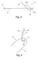
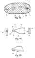
- the embolism protection device 1 comprises a frame 5 on which a filter unit 3 is arranged.
- the frame 5 is connected to a feed unit 7 .
- the length of the frame 5 is advantageously 50 to 100 mm.
- the width of the frame 5 is advantageously 15 to 45 mm.
- the frame 5 consists of a single continuously bent wire.
- the described properties and advantages of the embolic protection device also apply to other exemplary embodiments.
- the frame 5 has a two-dimensional and a three-dimensional area.
- the two-dimensional area ie the plane spanned by the frame, has an oval shape that merges into a proximal shape 11 and a distal shape 4 at the distal and proximal areas 2 , 9 .
- the proximal shape 11 and the distal shape 4 are the three-dimensional area of the frame 5, with the remaining area of the frame 5 forming the two-dimensional area, ie the oval shape.
- the embolic protection device 1 is shown in its basic form.
- FIG. 12 shows a plan view of the frame 5 of the embolic protection device 1 from FIG figure 1 .
- the proximal portion 9 of the frame 5 is that which opens into the open ends 17, 19 of the frame 5, in this embodiment the ends of the wire.
- the proximal area 9, and thus also the proximal shape 11, is defined by the two loose ends 17, 19 of the frame 5 or wire used.
- the proximal form 11 has a first part 13 and a second part 15 formed by the parallel ends 17, 19 in this embodiment.
- the frame 5 transitions into a distal shape 4 .
- the distal form 4 has a constriction 12 of the wire in the interior of the frame 5, or in other words in the interior of the oval two-dimensional area, of about 1-3 cm.
- the constriction 12 is a loop with a head diameter of about 1-1.8 mm and the wire otherwise lying parallel to one another.
- the loop and the wire lying parallel to each other are in the same two-dimensional plane of the frame 5.
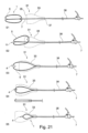
- figure 3 12 shows a side view of the frame 5 from FIG figure 2
- the proximal form 11 extends parallel to the ends of the frame 17, 19 as well as the frame in the distal form 4 into the interior of the frame 5.
- the first part 13 of the proximal form to the two-dimensional plane of the frame 5 has a first angle W1 of preferably 25 to 50 degrees downwards, the angle being measured from the first part 13 to the plane of the frame.
- a second part 15 is arranged at the end of the first part 13 at a second angle W2 of preferably 110 to 145 degrees upwards from the two-dimensional plane of the frame 5, the angle is measured from the second part 15 towards the plane of the frame.
- the length of the second part 15 is 1 to 5 cm.
- the lengths of the first and second parts 13, 15 as well as their angle to the plane of the frame 5 can also be larger or smaller according to the requirements of the embolic protection device.
- the first and second parts 13, 15 form the proximal form 11 which is arranged in an inner region of the frame 5, the proximal form 11 extending above and below the plane of the frame 5.
- This geometric shape of the proximal shape 11 prestresses the frame 5 and at the same time stabilizes it in the longitudinal and transverse directions.
- the first part 13 extends into the plane of the frame 5, ie the angle W1 is equal to 0 degrees and only the second part 15 is inclined to the plane of the frame 5 by a second angle W2.
- Figure 12 shows a perspective view of the proximal portion 9 of the frame of Figure 12 figure 2 .
- the proximal form 11 comprises the first part 13, which is bent at a first angle W1 to the plane of the frame 5, the second part 15, which is bent at a second angle W2 to the plane of the frame 5, and the two ends 17, 19 of the frame 5
- Both the first part 13 and the second part 15 of the proximal form 11 each have two frame wires.
- Figure 5A and 5B 12 show a frame 5 with a configuration of radiopaque markers 20.
- the radiopaque markers 20 are attached to the frame 5 at prominent locations for radiopaque visibility.
- the radiopaque markers 20 are attached in the area of the constriction 12 and on the frame in the distal area 2, so that the exact position of the tip of the frame 5 can be determined.
- radiopaque markers 20 are attached to the frame 5 outside of the distal or proximal area 2 , 9 .
- the distance between the marks 20 can be used to determine the stage in which the embolic protection device 1 is being folded or unfolded.
- the exact position of the embolism protection device 1 in the aortic arch can also be determined using the radiopaque markers 20 .
- the radiopaque markers can be platinum/iridium sleeves that are slid or clipped onto the frame.
- the sleeves have a slightly larger inside diameter than the frame 5, have a wall thickness of about 50-100 ⁇ m and are fixed with an adhesive.
- figure 6 shows a connection of a proximal form 11 according to the invention with a delivery device 7 according to the invention, the ends 17, 19 of the frame 5 of the proximal form 11 being shown in the drawing.
- the ends 17, 19 are also the end of the second part 15 of the proximal form 11.
- the feed unit 7 comprises a stainless steel coil and the casing is sealed.
- the outer diameter of the delivery unit 7 is 1.5 mm and its open lumen has a diameter of 0.8 mm.
- the total length of the feeding unit 7 is 150 cm. Other dimensions for the feed unit 7 are possible.
- the proximal form 11 of the frame 5 is connected to the feed unit 7 via an adhesive unit 8, for example polyurethane adhesive.
- the wire ends 17, 19 of the proximal form 11 are pushed into the open inner lumen of the delivery unit 7 and glued.
- the gluing unit 8 is hatched in the figure.
- the wire ends 17, 19, ie the second part 15 of the proximal form 11, are fixed by means of a wrapped stainless steel wire 6.
- the wire ends 10 of the wrapped stainless steel wire 6 are glued parallel to the ends 17, 19 of the frame 5 in the feed unit 7.
- the transition from the proximal form 11 to the feed unit 7 and the wrapped stainless steel wire 6 are also coated with polyurethane to ensure a smooth surface and to ensure a smooth transition.
- figure 7 shows an enlarged view of the connection of frame 5 and filter unit 3, shown in section.
- the connection is made as an enveloping polymer mold around the frame 5 .
- the polymer mold forms an adhesive tunnel 41 in which the frame 5 on the filter unit 3 is arranged.
- the seal 42 is shown on the outer edge of the filter unit 3 in this figure.
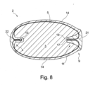
- figure 8 shows a plan view of a frame 5 with a filter unit 3 arranged thereon.
- the length of the frame 5 is advantageously 50 to 100 mm.
- the width of the frame 5 is advantageously 15 to 45 mm.
- the filter unit 3 is fixed to the frame 5 by means of an adhesive or an adhesive based on polyurethane.
- the bond runs continuously on the outer part of the frame 5.
- the parts of the frame 5 in the proximal and distal area, which are folded inwards in the basic form, are not bonded to the filter unit 3.
- the filter unit 3 is glued to the frame 5 from the underside so that the surface of the filter unit 3 faces the central blood flow entirely when the frame 5 is positioned in its placement position in the aortic arch.
- the frame 5, made of nitinol in this exemplary embodiment, is bonded to the filter unit 3 in a prestressed state in order to achieve an improved clamping force of the frame 5.
- the width of the frame 5 is compressed from 35-45mm to 25-35mm.
- the filter unit 3 protrudes with a projection 14 of about 1 mm over the frame 5 on its upper side and is folded or folded over in the distal and proximal area 2, 9 of the frame 5 from the underside over the frame 5 to the upper side.
- the projection 14 of the attached filter unit 3 beyond the outer edge of the frame 5 has the additional function of a flexible sealing lip towards the aortic wall when the embolic protection device 1 is in the placement position in the aortic arch.
- the folded area of the filter unit 3 comprises a proximal filter unit 21 and a distal filter unit 22.
- the proximal and distal filter units 21, 22 are not fixed to the frame with adhesive, so that a desired deformation is promoted when the catheter is pushed through.
- the proximal filter unit 21 is fixed together with the second part 15 of the proximal form 11 under the wrapped stainless steel wire 6 and sealed in this area, see also the illustration in figure 7 .
- the distal filter unit 22 is attached to the constriction 12 of the distal form 4 .
- the distal filter unit 22 extends further into the interior of the frame 5 via the constriction 12 by about 2-5 mm and is additionally flexibly sealed.
- the fibers of the filter unit 3 are aligned so that they are oriented at a 45° angle to the center line of the frame 5 from end to end. This allows the filter unit 3 to stretch better in the longitudinal direction, while the transverse direction offers stability.
- the outer edge of the projections 14 and 21 and 22 are additionally sealed.
- FIG 9 shows an end area of the distal filter unit 22 of the filter unit 3 figure 8 .
- the distal filter unit 22 is cut in such a way that it not only extends about 2 mm beyond the constriction 12 but also becomes wider again behind the constriction 12 and assumes the shape of a small flag 23 .
- This flag 23 is rolled up. The ends of the thread used are enclosed inside the flag 23 for fixing. Adhesive fixes the distal filter unit 23 against unrolling. The diameter of the rolled distal filter unit 22 is less than 1.6 mm. In addition to fixing the distal filter unit 23, an additional protective cushion is also formed between the frame 5 and the aortic wall in order to prevent injuries.
- figure 10 shows a plan view of a proximal form 11 with the filter unit 3 arranged.
- the proximal filter unit 21 is wrapped around the frame 5 towards the top.
- both the first part 13 of the proximal form 11 and the second part 15 of the proximal form 11 are wrapped with a stainless steel wire 6 (to better illustrate the stainless steel wire, the first and second parts 13, 15 of the proximal form are not shown).
- the first part 13 has a first angle W1 to the plane of the frame 5 and the second part 15 is bent at a second angle W2 to the plane of the frame 5 .
- figure 11 14 shows a perspective view of the proximal mold 11 from FIG figure 10 .
- figure 12 shows a plan view of a distal form 4 with an arranged filter unit 3, in particular a distal filter unit 22.
- the distal filter unit 22 is attached to the constriction 12 of the distal form 4 by means of a thread 43, which in other embodiments can also be a yarn or wire and protrudes inside the frame 5.
- figure 13 shows a plan view of a proximal form 11 with an arranged filter unit 3.
- the flag 23 is rolled up, with a thread being used to fix it, as in FIG figure 9 described and not repeated here.
- FIG 14 shows a folded embolic protection device 1 in a catheter 25.
- the embolic protection device 1 is in a folded state.
- the basic form of the embolic protection device such as in the Figures 1 to 13 shown, converted to the folded state.
- the reversibly deformable material of the frame 5, for example a superelastic nitinol wire, can be deformed in such a way that the embolism protection device 1 can be pushed into a catheter 25.
- the embolic protection device 1 stretches along its direction.
- the distal shape 4 and the proximal shape 11 are folded over into an outer area of the frame 5 .
- the frame 5 transitions into a straight or stretched shape.
- the associated change in length is due to the reduction in the width of the frame 5.
- the filter unit 3 can use this mechanical Deformation follow and settles in the space between catheter 25 and frame 5.
- the embolism protection device can be pushed into a catheter with an internal diameter of 1.7 mm, for example.
- Figure 15A-F 1 shows a reshaping of a frame 5 of an embolic protection device 1 according to the invention from a folded state into an unfolded state.
- the embolic protection device When the embolic protection device is positioned out of a catheter 25, for example in the aortic arch, the embolic protection device 1, in particular the frame 5 with the filter unit 3 arranged on it, is pushed out of the catheter 25. This is in the Figures 15A-F shown.
- the frame 5 which is made of reversibly deformable material, attempts to retain its original basic shape, such as in figure 1 shown to take back.
- the filter unit 3 arranged on the frame 5 follows the reshaping. Due to the advancement of the distal form 4 lying in the catheter 25, which is folded forward, this folds back halfway in the direction of the originally intended position when leaving the catheter 25, after about 1-2 cm advancement, cf. Figure 15A .
- the direction of the distal shape 4 indicates the position in which the embolism protection device 1 is located inside the catheter 25 .
- X-ray opaque markers that can be attached to the distal form 4 allow the position of the distal form 4 to be identified. The placement position, for example in the aortic arch, can be adjusted by rotating the catheter 25 .
- the frame 5 is wrapped on the distal form 4 with atraumatic material which has a projection of about 1-2 mm and thereby also counteracting possible injuries.
- Figure 15D shows the same state of development as Figure 15C from a side view, where Figure 15C shows the unfolding state viewed from above.
- Figure 15E shows the fully deployed frame or embolic protection device 1 viewed from above and in FIG Figure 15F from a side view.
- the effect of the spring mechanism through the proximal form 11 is from the transition from Figure 15C to Figure 15E or Figure 15D to Figure 15F evident.
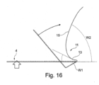
- figure 16 shows schematically an unfolded state of the embolism protection device 1 after leaving a catheter 25. Due to the special geometry of the proximal shape 11 up to the transition to the delivery unit 3, there is a pretension on the frame 5 to the same extent as the pre-bent proximal shape 11 is straightened.
- the figure shows two different states of the unfolded state.
- the position of the filter unit is identical in both illustrations.
- the position of the first and second parts 13, 15, which are connected to the feed unit (not shown), is shown both in the relaxed state and in the tensioned state. This results in a spring function, which is explained in more detail below.
- the transmitted tension of the proximal form 11 presses the distal form 4 against the aortic wall and thus allows stable fixation against the blood flow - in figure 16 this is shown sketchily by the thick, short arrow on the distal form 4.
- the proximal form 11 follows a movement represented by the thin curved arrow. Without the resistance of the aortic wall, the frame 5 would follow the folding direction shown - in figure 16 the curved thin arrow - such as in Figure 15E-F shown.
- the proximal shape 11 transitions to a shape in which the first part 13 has a first angle W1 of 25 to 50 degrees above the plane of the frame measured from the plane towards the first part 13 and the second part 15 has an angle W2 from 30 to 110 degrees above the plane of the frame measured from the second part 15 towards the plane.
- Specified degrees of the angles depend on the aortic geometry and are only examples.
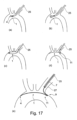
- figure 17 shows a schematic sequence of an unfolding of an embolism protection device 1 after leaving a catheter 25 in an aortic arch.
- Part (a) of the figure shows the introduction of the catheter 25 through the left subclavian artery, with the distal form 4 of the embolism protection device 1 being at least partially folded back.
- Figure parts (b) to (d) show the further advance and the unfolding of the embolism protection device 1, wherein in figure part (d) the proximal form 11 has also left the catheter.
- Part (e) of the figure shows the fully unfolded embolic protection device 1 in the placement state.
- the proximal area 9 of the frame 5 protrudes beyond the surface of the ostium of the left subclavian artery, as a result of which the embolism protection device 1 also covers the access route.
- this overhang offers haptic feedback when positioning the embolic protection device: by pulling on the delivery unit 7, a slight resistance can be felt as soon as the overhang of the embolic protection device 1, more precisely the frame 5, is correctly in front of the ostium 27.
- the intended position is via the left subclavian artery in the aortic arch with the distal area 2 of the frame 5 in the direction of the heart valve.
- the right subclavian artery can also serve as an alternative access route.
- the process is similar to that in figure 16 shown but mirrored.
- the distal area 2 of the frame 5 points in the direction of the descending aorta (descendens).
- FIG figure 18 shows a covering of the head vessel outlets 29 in the aorta by the embolism protection device 1 after leaving the catheter 25 as in FIG figure 17 . Due to the special geometry of the frame 5, the embolism protection device 1 adapts flexibly and independently to the anatomical conditions in the aortic arch and offers complete coverage of all head vessels 29.
- the geometry of the frame 5 of the embolism protection device 1 adapts flexibly to the aortic wall and lies in a slight curve, following the curvature of the aorta, in front of the head vessel outlets—cf. also Figure 17(e) .
- both the distal shape 4 and the proximal shape 11 fold back towards their original shape, ie towards the interior of the frame 5, thus enabling the frame 5 to be positioned atraumatically on the aortic wall. Folding over avoids sharp-edged transitions or corners.
- An additional stabilization of the frame 5 is achieved by the physiological conditions in the aorta, since the blood flow additionally presses the frame 5 of the embolic protection device 1 into its placement position.
- FIG 19 shows a shaping device 31 for shaping an embolism protection device 1 according to the invention in different views.
- the embolic protection device is drawn into the distal section 33 of the shaping device 31 .
- the distal section 33 of the shaping device 31 has a flat funnel with a flat opening 35 with an opening width of approx. 25-40 mm and an opening height of approx. 3-10 mm.
- the opening area of the front side tapers to a narrowest circular cross-section 39 with a diameter of about 1.7 mm.
- the proximal portion 40 of the shaping device 31 expands from the narrowest cross-section 39 towards the round opening 37 to a diameter of approximately 1.8 to 5 mm over a length of 20 to 40 mm. This results in an overall length of the molding device 31 of 80 to 120 mm.
- FIG. 14 is a perspective view of the molding device 31.
- FIG figure 19 is a perspective view of the molding device 31.
- figure 21 shows individual steps of the method for folding the embolic protection device according to the invention using a shaping device 31, the folded embolic protection device 1 being inserted into a substantially circular tube 38, e.g. a commercially available introducer sheath or a commercially available catheter (with an inner diameter of 1.8 to 2.5 mm) 38 is pushed.
- a step S1 the frame 5 of the embolic protection device 1 is pushed in front of the flat opening 35 of the molding device 31, with the delivery unit 7 in front.
- the proximal end of the feed unit 7 is guided through the distal end of the shaping device 31 .
- the substantially circular hose 38 is pushed with its distal end onto the feed unit 7 from the proximal end up to the round opening 37 of the shaping device 31 , with the feed unit 7 protruding from this hose 38 .
- a step S2 the tube 38 and the mold 31 are connected to each other in the enlarged or cone-shaped round opening 37 of the mold 31, for example, by a push-fit connection.
- the embolic protection device 1 is aligned by pulling on the delivery unit 7 .
- a step S3 the proximal form 11 is folded over at the outer edge of the distal partial area 33 of the forming device 31 , so that it is stretched and pulled through the forming device 31 .
- step S4 in the distal shape 4 is pushed over the outer edge of the distal section 33 of the shaping device 31, the distal shape 4 hooking onto the edge and being folded over outwards. This is also illustrated in the side view in the figure.
- a step S5 the embolism protection device 1 is drawn through the molding device 31 in a fully stretched manner.
- the sides of the frame 5 are pushed inwards until the whole frame is drawn elongated into the tube 38.
- the embolic protection device 1 remains in this tube 38.
- the shaping device 31 can now be removed from the tube 38.
- an embolism protection device (1) according to the invention is designed for delivery into an aortic arch, comprising a filter unit (3), a frame (5) and a delivery unit (7), the filter unit (3) on the frame (5) is arranged and the frame (5) has a proximal portion (9) comprising a proximal form (11) which is arranged in an inner portion of the frame (5) and is connected to the delivery unit (7), wherein the A proximal mold (11) comprises a first part (13) and a second part (15), the second part (15) being formed at an end of the first part (13).
- the first part (13) of the proximal shape (11) has a first angle (W1) to the frame (5) level and the second part (15) to the first part (13) of the proximal shape ( 11) a second angle (W2).
- an embolism protection device (1) for delivery into an aortic arch comprising a filter unit (3), a frame (5) and a delivery unit (7), the filter unit (3) being arranged on the frame (5) and the frame ( 5) has a proximal portion (9) comprising a proximal form (11) which is arranged in an inner portion of the frame (5) and is connected to the delivery unit (7), the proximal form (11) having a first part (13 ) and a second part (15), wherein the first and second parts (13, 15) are arranged relative to one another in such a way that they form a spring mechanism.
- the proximal form (11) can be tensioned via the supply unit (7).
- the proximal shape (11) comprises two ends (17, 19) of the frame (5), which extend parallel to one another in the interior area of the frame (5). extend.
- the proximal form (11) is connected to the delivery unit (7), the two ends (17, 19) of the frame (5) being wrapped in a wire (6), the ends (10) of which are arranged parallel to the ends (17, 19) of the frame (5).
- the frame (5) has a distal area (2) which includes a distal shape (4) which is arranged in an inner area of the frame (5).
- the distal shape (4) has a constriction (12) directed towards the inside of the frame (5).
- the frame (5) and filter unit (3) are connected by means of an adhesive tunnel or an adhesive tunnel connection.
- the filter unit (3) is connected to the frame (5) outside the proximal and/or distal area (9, 2).
- the filter unit (3) is connected to the frame (5) in the distal area (2) essentially up to the beginning of the distal shape (4).
- the filter unit (3) is connected to the frame (5) in the proximal area (2) essentially up to the first part (13) of the proximal shape (11).
- the filter unit (3) is flexibly connected to the frame (5) in the distal and proximal areas (2, 9).
- the frame (5) is connected to the filter unit (3) in a pretensioned manner in the transverse direction.
- the filter unit (3) has a projection (14) over the frame (5).
- the overhang (14) is sealed.
- the overhang (14) is designed as a sealing lip.
- the filter unit (3) is folded over the frame (5) from the bottom to the top in the proximal and/or distal area (9, 2) of the frame (5).
- the filter unit (3) is attached to the distal form (4) by means of a thread, wire or yarn.
- the fastening of the filter unit (3) is sealed to the distal form (4) by means of a thread, wire or yarn.
- the filter unit (3) is attached to the distal form (4) by means of an adhesive bond.
- the filter unit (3) is fixed in the proximal area (9) by means of a coil.
- the filter unit (3) has a fiber material, the fibers being aligned in such a way that they have an angle of essentially 45 degrees to a longitudinal axis of the frame (5).
- the frame (5) has a basic shape which is designed as an oval shape.
- a shaping device (31) for shaping the embolic protection device (1) is specified for drawing into a tube, a frame (5) with a filter unit (3) arranged thereon of the embolic protection device (1) being shaped from an expanded state into a stretched state is, comprising a one-sided flat or round opening (35), a narrowest cross-section (39) and an opposite round opening (37).
- the flat or round opening (35) of the shaping device (31) is designed in such a way that the proximal shape (11) and/or the distal shape (4) of the frame (5) of the embolic protection device is folded outwards.
- a method for folding the embolic protection device by means of the shaping device comprising pushing (S1) the frame (5) of the embolic protection device in front of the flat or round opening (35) of the shaping device (31), the feed unit (7) passing through the shaping device ( 31) is passed through, pulling (S3) the proximal form (11) into the forming device (31), whereby the proximal form (11) is folded over outwards, hooking (S4) the distal form (4) over the outer edge of the forming device (31) , wherein the distal form (4) is folded outwards and drawn into the forming device (31) by further pulling.
- the frame (5) is elongated by drawing the frame (5) into the shaping device (31).
- the folded proximal shape (11) transmits a prestress to the frame (5) which is essentially equal to the stress resulting therefrom, the curved proximal shape (11) is straightened.
- a method for deploying the embolic protection device is specified when the embolic protection device leaves a catheter containing it, comprising pushing the embolic protection device out of the catheter, Folding the distal form (4) back into an interior portion of the frame (5) when a distal portion (2) of the frame of the embolic protection device exits the catheter.
- a further development of the method includes indicating the direction of the frame (5) via one or more markers when the distal area (2) leaves the catheter, the distal area (2) indicating the direction of the frame (5).
Landscapes
- Health & Medical Sciences (AREA)
- Life Sciences & Earth Sciences (AREA)
- Veterinary Medicine (AREA)
- Heart & Thoracic Surgery (AREA)
- Vascular Medicine (AREA)
- Animal Behavior & Ethology (AREA)
- General Health & Medical Sciences (AREA)
- Public Health (AREA)
- Engineering & Computer Science (AREA)
- Biomedical Technology (AREA)
- Cardiology (AREA)
- Transplantation (AREA)
- Oral & Maxillofacial Surgery (AREA)
- Surgery (AREA)
- Orthopedic Medicine & Surgery (AREA)
- Chemical & Material Sciences (AREA)
- Medical Informatics (AREA)
- Molecular Biology (AREA)
- Nuclear Medicine, Radiotherapy & Molecular Imaging (AREA)
- Inorganic Chemistry (AREA)
- Epidemiology (AREA)
- Surgical Instruments (AREA)
- Shaping Of Tube Ends By Bending Or Straightening (AREA)
- Details Of Indoor Wiring (AREA)
- Protection Of Pipes Against Damage, Friction, And Corrosion (AREA)
- Prostheses (AREA)
Applications Claiming Priority (3)
| Application Number | Priority Date | Filing Date | Title |
|---|---|---|---|
| DE102016012869.0A DE102016012869A1 (de) | 2016-10-28 | 2016-10-28 | Embolieschutzvorrichtung, Verfahren zu deren Faltung und Formvorrichtung |
| EP17781388.8A EP3531967B1 (fr) | 2016-10-28 | 2017-09-18 | Dispositif de protection embolique, procédé pour son repliement et procédé de moulage |
| PCT/EP2017/001097 WO2018077458A1 (fr) | 2016-10-28 | 2017-09-18 | Dispositif de protection embolique, procédé pour son repliement et procédé de moulage |
Related Parent Applications (1)
| Application Number | Title | Priority Date | Filing Date |
|---|---|---|---|
| EP17781388.8A Division EP3531967B1 (fr) | 2016-10-28 | 2017-09-18 | Dispositif de protection embolique, procédé pour son repliement et procédé de moulage |
Publications (2)
| Publication Number | Publication Date |
|---|---|
| EP4201377A2 true EP4201377A2 (fr) | 2023-06-28 |
| EP4201377A3 EP4201377A3 (fr) | 2023-09-20 |
Family
ID=60051464
Family Applications (2)
| Application Number | Title | Priority Date | Filing Date |
|---|---|---|---|
| EP17781388.8A Active EP3531967B1 (fr) | 2016-10-28 | 2017-09-18 | Dispositif de protection embolique, procédé pour son repliement et procédé de moulage |
| EP23153052.8A Pending EP4201377A3 (fr) | 2016-10-28 | 2017-09-18 | Dispositif de protection embolique, procédé de pliage associé et dispositif de moulage |
Family Applications Before (1)
| Application Number | Title | Priority Date | Filing Date |
|---|---|---|---|
| EP17781388.8A Active EP3531967B1 (fr) | 2016-10-28 | 2017-09-18 | Dispositif de protection embolique, procédé pour son repliement et procédé de moulage |
Country Status (21)
| Country | Link |
|---|---|
| US (2) | US11534284B2 (fr) |
| EP (2) | EP3531967B1 (fr) |
| JP (2) | JP2019532780A (fr) |
| KR (1) | KR102534442B1 (fr) |
| CN (2) | CN109890324B (fr) |
| AU (1) | AU2017348921B2 (fr) |
| BR (1) | BR112019008638B1 (fr) |
| CA (1) | CA3041606A1 (fr) |
| CR (1) | CR20190213A (fr) |
| DE (1) | DE102016012869A1 (fr) |
| DK (1) | DK3531967T3 (fr) |
| ES (1) | ES2941812T3 (fr) |
| FI (1) | FI3531967T3 (fr) |
| HU (1) | HUE061808T2 (fr) |
| IL (1) | IL266244B2 (fr) |
| MX (1) | MX2019004964A (fr) |
| PL (1) | PL3531967T3 (fr) |
| PT (1) | PT3531967T (fr) |
| RU (1) | RU2742690C2 (fr) |
| SG (2) | SG11201903733UA (fr) |
| WO (1) | WO2018077458A1 (fr) |
Families Citing this family (8)
| Publication number | Priority date | Publication date | Assignee | Title |
|---|---|---|---|---|
| EP3426188B1 (fr) | 2016-03-10 | 2022-09-21 | Keystone Heart Ltd. | Dispositif intra-aortique |
| DE102016012869A1 (de) * | 2016-10-28 | 2018-05-03 | Protembis Gmbh | Embolieschutzvorrichtung, Verfahren zu deren Faltung und Formvorrichtung |
| EP3400901A1 (fr) * | 2017-05-12 | 2018-11-14 | Keystone Heart Ltd. | Dispositif de filtrage de matériau embolique dans un système vasculaire |
| AU2019273861B2 (en) * | 2018-05-22 | 2024-10-31 | Filterlex Medical Ltd. | Intra-aortic embolic protection filter device |
| DE102020110715A1 (de) * | 2019-06-28 | 2020-12-31 | Protembis Gmbh | Embolieschutzvorrichtung zur Zuführung in einen Aortenbogen |
| CN112914789A (zh) * | 2020-11-05 | 2021-06-08 | 上海微创医疗器械(集团)有限公司 | 抗栓塞保护装置及医疗器械 |
| KR102900410B1 (ko) | 2022-06-21 | 2025-12-16 | 주식회사 바스노바 | 경동맥 필터 와이어 및 경동맥 필터 시스템 |
| CN115887057A (zh) * | 2023-01-06 | 2023-04-04 | 成都纽脉生物科技有限公司 | 血管栓塞滤网组件和栓塞过滤设备 |
Citations (1)
| Publication number | Priority date | Publication date | Assignee | Title |
|---|---|---|---|---|
| EP2859864A1 (fr) | 2013-10-14 | 2015-04-15 | Protembis GmbH | Dispositif médical destiné à une protection embolique |
Family Cites Families (21)
| Publication number | Priority date | Publication date | Assignee | Title |
|---|---|---|---|---|
| US7014647B2 (en) | 1999-05-07 | 2006-03-21 | Salviac Limited | Support frame for an embolic protection device |
| US20100324589A1 (en) | 2006-09-11 | 2010-12-23 | Carpenter Judith T | Embolic deflection device |
| US20100179583A1 (en) * | 2006-09-11 | 2010-07-15 | Carpenter Judith T | Methods of deploying and retrieving an embolic diversion device |
| US8460335B2 (en) | 2006-09-11 | 2013-06-11 | Embrella Cardiovascular, Inc. | Method of deflecting emboli from the cerebral circulation |
| US8764816B2 (en) * | 2007-05-07 | 2014-07-01 | W. L. Gore & Associates, Inc. | Stent delivery and deployment system |
| DE202009018998U1 (de) * | 2008-09-04 | 2015-04-29 | Swat Medical Ab | Faltbare temporäre Embolieschutzvorrichtung mit länglicher blutdurchlässiger Einheit |
| EP2654617B1 (fr) * | 2010-12-23 | 2020-06-03 | Keystone Heart Ltd. | Dispositif de déviation d'emboles dans une aorte |
| AU2012211992C1 (en) * | 2011-02-04 | 2016-07-21 | Concentric Medical, Inc. | Vascular and bodily duct treatment devices and methods |
| EP2770951A1 (fr) * | 2011-10-25 | 2014-09-03 | Boston Scientific Scimed, Inc. | Déflecteur de débris emboliques |
| WO2013074521A1 (fr) * | 2011-11-14 | 2013-05-23 | Boston Scientific Scimed, Inc. | Dispositif et méthode de protection d'une embolie |
| WO2013126618A1 (fr) * | 2012-02-21 | 2013-08-29 | Synecor Llc | Système de protection embolique et procédé d'utilisation dans une crosse aortique |
| US20140074148A1 (en) | 2012-02-21 | 2014-03-13 | Synecor Llc | Embolic protection system and method for use in an aortic arch |
| EP2732794A1 (fr) * | 2012-11-14 | 2014-05-21 | Contego AB | Dispositif de protection embolique amélioré et procédé |
| US10307240B2 (en) * | 2012-12-11 | 2019-06-04 | Alan Zajarias | Methods and apparatus for capturing embolic debris during endovascular procedures |
| US9211178B2 (en) * | 2013-02-26 | 2015-12-15 | Medtronic, Inc. | Embolic protection device |
| EP2967602B1 (fr) * | 2013-03-15 | 2019-08-28 | Volcano Corporation | Systèmes de protection distale faisant intervenir des accessoires de pression et à ultrasons |
| CN110215312A (zh) * | 2014-01-10 | 2019-09-10 | 企斯动哈特有限公司 | 用于偏转栓塞的装置和相关系统 |
| CN107072770B (zh) | 2014-05-21 | 2020-06-16 | Swat医疗有限公司 | 改进的防栓塞保护装置及方法 |
| US20160175084A1 (en) * | 2014-12-19 | 2016-06-23 | Volcano Corporation | Biodegradable filter and support frame |
| JP6716580B2 (ja) * | 2015-04-16 | 2020-07-01 | サンフォード ヘルス | 血管フィルタ及び使用方法 |
| DE102016012869A1 (de) * | 2016-10-28 | 2018-05-03 | Protembis Gmbh | Embolieschutzvorrichtung, Verfahren zu deren Faltung und Formvorrichtung |
-
2016
- 2016-10-28 DE DE102016012869.0A patent/DE102016012869A1/de active Pending
-
2017
- 2017-09-18 US US16/345,369 patent/US11534284B2/en active Active
- 2017-09-18 SG SG11201903733UA patent/SG11201903733UA/en unknown
- 2017-09-18 PT PT177813888T patent/PT3531967T/pt unknown
- 2017-09-18 CR CR20190213A patent/CR20190213A/es unknown
- 2017-09-18 EP EP17781388.8A patent/EP3531967B1/fr active Active
- 2017-09-18 CA CA3041606A patent/CA3041606A1/fr active Pending
- 2017-09-18 AU AU2017348921A patent/AU2017348921B2/en active Active
- 2017-09-18 RU RU2019116460A patent/RU2742690C2/ru active
- 2017-09-18 BR BR112019008638-2A patent/BR112019008638B1/pt active IP Right Grant
- 2017-09-18 ES ES17781388T patent/ES2941812T3/es active Active
- 2017-09-18 CN CN201780067140.2A patent/CN109890324B/zh active Active
- 2017-09-18 CN CN202211602859.0A patent/CN115778625A/zh active Pending
- 2017-09-18 IL IL266244A patent/IL266244B2/en unknown
- 2017-09-18 EP EP23153052.8A patent/EP4201377A3/fr active Pending
- 2017-09-18 HU HUE17781388A patent/HUE061808T2/hu unknown
- 2017-09-18 PL PL17781388.8T patent/PL3531967T3/pl unknown
- 2017-09-18 SG SG10202104323RA patent/SG10202104323RA/en unknown
- 2017-09-18 WO PCT/EP2017/001097 patent/WO2018077458A1/fr not_active Ceased
- 2017-09-18 KR KR1020197015339A patent/KR102534442B1/ko active Active
- 2017-09-18 DK DK17781388.8T patent/DK3531967T3/da active
- 2017-09-18 JP JP2019523862A patent/JP2019532780A/ja active Pending
- 2017-09-18 FI FIEP17781388.8T patent/FI3531967T3/fi active
- 2017-09-18 MX MX2019004964A patent/MX2019004964A/es unknown
-
2022
- 2022-08-15 JP JP2022129177A patent/JP7386941B2/ja active Active
- 2022-12-19 US US18/068,417 patent/US20230121543A1/en active Pending
Patent Citations (1)
| Publication number | Priority date | Publication date | Assignee | Title |
|---|---|---|---|---|
| EP2859864A1 (fr) | 2013-10-14 | 2015-04-15 | Protembis GmbH | Dispositif médical destiné à une protection embolique |
Also Published As
Similar Documents
| Publication | Publication Date | Title |
|---|---|---|
| EP3531967B1 (fr) | Dispositif de protection embolique, procédé pour son repliement et procédé de moulage | |
| DE10334868B4 (de) | Implantierbare Einrichtung als Organklappenersatz, dessen Herstellungsverfahren sowie Grundkörper und Membranelement dafür | |
| EP2303198B1 (fr) | Implant à membrane destiné au traitement d'anévrismes cérébraux | |
| DE69607602T2 (de) | Ösophagischer, dilatationballonkatheter mit flexiblem nitinoldraht | |
| EP2884946B1 (fr) | Dispositif implantable destiné à être utilisé dans un corps humain et/ou animal pour remplacer un clapet organique | |
| DE69116351T2 (de) | Vorrichtung zum zeitlichen Einsetzen eines Blutfilters in eine Vene des menschlichen Körpers | |
| DE10362223B4 (de) | Grundwickelform | |
| DE69637303T2 (de) | Führungsdraht mit lösbarem Anker | |
| DE60105302T2 (de) | Vaskuläre okklusionsvorrichtung, sowie gerät zu ihrer verwendung | |
| DE69532267T2 (de) | Katheter für Stentimplantation | |
| DE102008028308A1 (de) | Vaskuläres Implantat und Verfahren zum Herstellen eines derartigen Implantats | |
| DE112009001316T5 (de) | Vorrichtung zur Behandlung eines Blutkreislaufkanals | |
| DE102010037529A1 (de) | Einrichtung, vorgesehen, um an einem Katheter befestigt oder mit diesem verbunden zu werden, Katheter und Verfahren | |
| DE102013017750A1 (de) | Implantierbare Vorrichtung zur Verbesserung oder Behebung einer Herzklappeninsuffizienz | |
| DE10104806A1 (de) | Gefäßprothese | |
| DE102005015406B4 (de) | Abdeck- und Abhalteelement für die störungsfreie Vornahme dentaler Bearbeitungen an Zähnen sowie Verfahren zu dessen Herstellung | |
| DE2057181C3 (de) | Vorrichtung zum Verstopfen eines Blutgefäßes mit einem ausdehnbaren Verstopfungskörper | |
| DE10247023B4 (de) | Mikrodialysesonde und Verfahren zu deren Herstellung | |
| DE10162821A1 (de) | Gefässprothese, insbesondere zum Ersatz von herznahen Bereichen der Aorta | |
| DE19739103A1 (de) | Tracheotomiekanüle mit Schild | |
| EP1248578A1 (fr) | Instrument de penetration pour raccordement tubulaire prothetique | |
| DE3140192A1 (de) | Katheter | |
| DE102011015738A1 (de) | Stent zur transluminalen Implantation in Hohlorgane und Einführkatheter | |
| DE602004009540T2 (de) | Ausziehbare Vorrichtung mit Füllstoff zum Einbringen von Arzneimitteln in tierisches Gewebe | |
| EP3263153A1 (fr) | Dispositif pliable de rangement fonctionnel pour des éléments flexibles d'écoulement sanguin |
Legal Events
| Date | Code | Title | Description |
|---|---|---|---|
| PUAI | Public reference made under article 153(3) epc to a published international application that has entered the european phase |
Free format text: ORIGINAL CODE: 0009012 |
|
| STAA | Information on the status of an ep patent application or granted ep patent |
Free format text: STATUS: THE APPLICATION HAS BEEN PUBLISHED |
|
| AC | Divisional application: reference to earlier application |
Ref document number: 3531967 Country of ref document: EP Kind code of ref document: P |
|
| AK | Designated contracting states |
Kind code of ref document: A2 Designated state(s): AL AT BE BG CH CY CZ DE DK EE ES FI FR GB GR HR HU IE IS IT LI LT LU LV MC MK MT NL NO PL PT RO RS SE SI SK SM TR |
|
| PUAL | Search report despatched |
Free format text: ORIGINAL CODE: 0009013 |
|
| AK | Designated contracting states |
Kind code of ref document: A3 Designated state(s): AL AT BE BG CH CY CZ DE DK EE ES FI FR GB GR HR HU IE IS IT LI LT LU LV MC MK MT NL NO PL PT RO RS SE SI SK SM TR |
|
| RIC1 | Information provided on ipc code assigned before grant |
Ipc: A61F 2/01 20060101AFI20230817BHEP |
|
| P01 | Opt-out of the competence of the unified patent court (upc) registered |
Effective date: 20231221 |
|
| STAA | Information on the status of an ep patent application or granted ep patent |
Free format text: STATUS: REQUEST FOR EXAMINATION WAS MADE |
|
| 17P | Request for examination filed |
Effective date: 20240315 |
|
| RBV | Designated contracting states (corrected) |
Designated state(s): AL AT BE BG CH CY CZ DE DK EE ES FI FR GB GR HR HU IE IS IT LI LT LU LV MC MK MT NL NO PL PT RO RS SE SI SK SM TR |
|
| GRAP | Despatch of communication of intention to grant a patent |
Free format text: ORIGINAL CODE: EPIDOSNIGR1 |
|
| STAA | Information on the status of an ep patent application or granted ep patent |
Free format text: STATUS: GRANT OF PATENT IS INTENDED |
|
| INTG | Intention to grant announced |
Effective date: 20250715 |
|
| GRAJ | Information related to disapproval of communication of intention to grant by the applicant or resumption of examination proceedings by the epo deleted |
Free format text: ORIGINAL CODE: EPIDOSDIGR1 |
|
| STAA | Information on the status of an ep patent application or granted ep patent |
Free format text: STATUS: REQUEST FOR EXAMINATION WAS MADE |
|
| GRAS | Grant fee paid |
Free format text: ORIGINAL CODE: EPIDOSNIGR3 |
|
| STAA | Information on the status of an ep patent application or granted ep patent |
Free format text: STATUS: GRANT OF PATENT IS INTENDED |
|
| GRAP | Despatch of communication of intention to grant a patent |
Free format text: ORIGINAL CODE: EPIDOSNIGR1 |
|
| INTC | Intention to grant announced (deleted) | ||
| INTG | Intention to grant announced |
Effective date: 20251202 |
|
| GRAA | (expected) grant |
Free format text: ORIGINAL CODE: 0009210 |
|
| STAA | Information on the status of an ep patent application or granted ep patent |
Free format text: STATUS: THE PATENT HAS BEEN GRANTED |