EP4201505A1 - Wassersammelvorrichtung und wassersammelverfahren - Google Patents
Wassersammelvorrichtung und wassersammelverfahren Download PDFInfo
- Publication number
- EP4201505A1 EP4201505A1 EP21858293.0A EP21858293A EP4201505A1 EP 4201505 A1 EP4201505 A1 EP 4201505A1 EP 21858293 A EP21858293 A EP 21858293A EP 4201505 A1 EP4201505 A1 EP 4201505A1
- Authority
- EP
- European Patent Office
- Prior art keywords
- moisture
- absorbing material
- heat
- water collecting
- layer
- Prior art date
- Legal status (The legal status is an assumption and is not a legal conclusion. Google has not performed a legal analysis and makes no representation as to the accuracy of the status listed.)
- Pending
Links
Images






Classifications
-
- B—PERFORMING OPERATIONS; TRANSPORTING
- B01—PHYSICAL OR CHEMICAL PROCESSES OR APPARATUS IN GENERAL
- B01D—SEPARATION
- B01D53/00—Separation of gases or vapours; Recovering vapours of volatile solvents from gases; Chemical or biological purification of waste gases, e.g. engine exhaust gases, smoke, fumes, flue gases, aerosols
- B01D53/26—Drying gases or vapours
- B01D53/261—Drying gases or vapours by adsorption
-
- B—PERFORMING OPERATIONS; TRANSPORTING
- B01—PHYSICAL OR CHEMICAL PROCESSES OR APPARATUS IN GENERAL
- B01J—CHEMICAL OR PHYSICAL PROCESSES, e.g. CATALYSIS OR COLLOID CHEMISTRY; THEIR RELEVANT APPARATUS
- B01J20/00—Solid sorbent compositions or filter aid compositions; Sorbents for chromatography; Processes for preparing, regenerating or reactivating thereof
- B01J20/28—Solid sorbent compositions or filter aid compositions; Sorbents for chromatography; Processes for preparing, regenerating or reactivating thereof characterised by their form or physical properties
- B01J20/28014—Solid sorbent compositions or filter aid compositions; Sorbents for chromatography; Processes for preparing, regenerating or reactivating thereof characterised by their form or physical properties characterised by their form
- B01J20/28042—Shaped bodies; Monolithic structures
-
- B—PERFORMING OPERATIONS; TRANSPORTING
- B01—PHYSICAL OR CHEMICAL PROCESSES OR APPARATUS IN GENERAL
- B01D—SEPARATION
- B01D53/00—Separation of gases or vapours; Recovering vapours of volatile solvents from gases; Chemical or biological purification of waste gases, e.g. engine exhaust gases, smoke, fumes, flue gases, aerosols
- B01D53/02—Separation of gases or vapours; Recovering vapours of volatile solvents from gases; Chemical or biological purification of waste gases, e.g. engine exhaust gases, smoke, fumes, flue gases, aerosols by adsorption, e.g. preparative gas chromatography
-
- B—PERFORMING OPERATIONS; TRANSPORTING
- B01—PHYSICAL OR CHEMICAL PROCESSES OR APPARATUS IN GENERAL
- B01D—SEPARATION
- B01D53/00—Separation of gases or vapours; Recovering vapours of volatile solvents from gases; Chemical or biological purification of waste gases, e.g. engine exhaust gases, smoke, fumes, flue gases, aerosols
- B01D53/02—Separation of gases or vapours; Recovering vapours of volatile solvents from gases; Chemical or biological purification of waste gases, e.g. engine exhaust gases, smoke, fumes, flue gases, aerosols by adsorption, e.g. preparative gas chromatography
- B01D53/04—Separation of gases or vapours; Recovering vapours of volatile solvents from gases; Chemical or biological purification of waste gases, e.g. engine exhaust gases, smoke, fumes, flue gases, aerosols by adsorption, e.g. preparative gas chromatography with stationary adsorbents
- B01D53/0407—Constructional details of adsorbing systems
- B01D53/0438—Cooling or heating systems
-
- B—PERFORMING OPERATIONS; TRANSPORTING
- B01—PHYSICAL OR CHEMICAL PROCESSES OR APPARATUS IN GENERAL
- B01D—SEPARATION
- B01D53/00—Separation of gases or vapours; Recovering vapours of volatile solvents from gases; Chemical or biological purification of waste gases, e.g. engine exhaust gases, smoke, fumes, flue gases, aerosols
- B01D53/26—Drying gases or vapours
- B01D53/28—Selection of materials for use as drying agents
-
- B—PERFORMING OPERATIONS; TRANSPORTING
- B01—PHYSICAL OR CHEMICAL PROCESSES OR APPARATUS IN GENERAL
- B01J—CHEMICAL OR PHYSICAL PROCESSES, e.g. CATALYSIS OR COLLOID CHEMISTRY; THEIR RELEVANT APPARATUS
- B01J20/00—Solid sorbent compositions or filter aid compositions; Sorbents for chromatography; Processes for preparing, regenerating or reactivating thereof
- B01J20/22—Solid sorbent compositions or filter aid compositions; Sorbents for chromatography; Processes for preparing, regenerating or reactivating thereof comprising organic material
-
- B—PERFORMING OPERATIONS; TRANSPORTING
- B01—PHYSICAL OR CHEMICAL PROCESSES OR APPARATUS IN GENERAL
- B01J—CHEMICAL OR PHYSICAL PROCESSES, e.g. CATALYSIS OR COLLOID CHEMISTRY; THEIR RELEVANT APPARATUS
- B01J20/00—Solid sorbent compositions or filter aid compositions; Sorbents for chromatography; Processes for preparing, regenerating or reactivating thereof
- B01J20/22—Solid sorbent compositions or filter aid compositions; Sorbents for chromatography; Processes for preparing, regenerating or reactivating thereof comprising organic material
- B01J20/24—Naturally occurring macromolecular compounds, e.g. humic acids or their derivatives
-
- B—PERFORMING OPERATIONS; TRANSPORTING
- B01—PHYSICAL OR CHEMICAL PROCESSES OR APPARATUS IN GENERAL
- B01J—CHEMICAL OR PHYSICAL PROCESSES, e.g. CATALYSIS OR COLLOID CHEMISTRY; THEIR RELEVANT APPARATUS
- B01J20/00—Solid sorbent compositions or filter aid compositions; Sorbents for chromatography; Processes for preparing, regenerating or reactivating thereof
- B01J20/22—Solid sorbent compositions or filter aid compositions; Sorbents for chromatography; Processes for preparing, regenerating or reactivating thereof comprising organic material
- B01J20/26—Synthetic macromolecular compounds
- B01J20/265—Synthetic macromolecular compounds modified or post-treated polymers
- B01J20/267—Cross-linked polymers
-
- B—PERFORMING OPERATIONS; TRANSPORTING
- B01—PHYSICAL OR CHEMICAL PROCESSES OR APPARATUS IN GENERAL
- B01J—CHEMICAL OR PHYSICAL PROCESSES, e.g. CATALYSIS OR COLLOID CHEMISTRY; THEIR RELEVANT APPARATUS
- B01J20/00—Solid sorbent compositions or filter aid compositions; Sorbents for chromatography; Processes for preparing, regenerating or reactivating thereof
- B01J20/28—Solid sorbent compositions or filter aid compositions; Sorbents for chromatography; Processes for preparing, regenerating or reactivating thereof characterised by their form or physical properties
- B01J20/28014—Solid sorbent compositions or filter aid compositions; Sorbents for chromatography; Processes for preparing, regenerating or reactivating thereof characterised by their form or physical properties characterised by their form
- B01J20/28033—Membrane, sheet, cloth, pad, lamellar or mat
- B01J20/28035—Membrane, sheet, cloth, pad, lamellar or mat with more than one layer, e.g. laminates, separated sheets
-
- B—PERFORMING OPERATIONS; TRANSPORTING
- B01—PHYSICAL OR CHEMICAL PROCESSES OR APPARATUS IN GENERAL
- B01J—CHEMICAL OR PHYSICAL PROCESSES, e.g. CATALYSIS OR COLLOID CHEMISTRY; THEIR RELEVANT APPARATUS
- B01J20/00—Solid sorbent compositions or filter aid compositions; Sorbents for chromatography; Processes for preparing, regenerating or reactivating thereof
- B01J20/30—Processes for preparing, regenerating, or reactivating
- B01J20/34—Regenerating or reactivating
- B01J20/3425—Regenerating or reactivating of sorbents or filter aids comprising organic materials
-
- B—PERFORMING OPERATIONS; TRANSPORTING
- B01—PHYSICAL OR CHEMICAL PROCESSES OR APPARATUS IN GENERAL
- B01J—CHEMICAL OR PHYSICAL PROCESSES, e.g. CATALYSIS OR COLLOID CHEMISTRY; THEIR RELEVANT APPARATUS
- B01J20/00—Solid sorbent compositions or filter aid compositions; Sorbents for chromatography; Processes for preparing, regenerating or reactivating thereof
- B01J20/30—Processes for preparing, regenerating, or reactivating
- B01J20/34—Regenerating or reactivating
- B01J20/3483—Regenerating or reactivating by thermal treatment not covered by groups B01J20/3441 - B01J20/3475, e.g. by heating or cooling
-
- E—FIXED CONSTRUCTIONS
- E03—WATER SUPPLY; SEWERAGE
- E03B—INSTALLATIONS OR METHODS FOR OBTAINING, COLLECTING, OR DISTRIBUTING WATER
- E03B3/00—Methods or installations for obtaining or collecting drinking water or tap water
- E03B3/28—Methods or installations for obtaining or collecting drinking water or tap water from humid air
-
- B—PERFORMING OPERATIONS; TRANSPORTING
- B01—PHYSICAL OR CHEMICAL PROCESSES OR APPARATUS IN GENERAL
- B01D—SEPARATION
- B01D2253/00—Adsorbents used in seperation treatment of gases and vapours
- B01D2253/20—Organic adsorbents
- B01D2253/202—Polymeric adsorbents
-
- B—PERFORMING OPERATIONS; TRANSPORTING
- B01—PHYSICAL OR CHEMICAL PROCESSES OR APPARATUS IN GENERAL
- B01D—SEPARATION
- B01D2257/00—Components to be removed
- B01D2257/80—Water
-
- B—PERFORMING OPERATIONS; TRANSPORTING
- B01—PHYSICAL OR CHEMICAL PROCESSES OR APPARATUS IN GENERAL
- B01D—SEPARATION
- B01D2259/00—Type of treatment
- B01D2259/40—Further details for adsorption processes and devices
- B01D2259/40083—Regeneration of adsorbents in processes other than pressure or temperature swing adsorption
- B01D2259/40088—Regeneration of adsorbents in processes other than pressure or temperature swing adsorption by heating
- B01D2259/40098—Regeneration of adsorbents in processes other than pressure or temperature swing adsorption by heating with other heating means
Definitions
- the present invention relates to a water collecting apparatus and a water collecting method.
- PTL 1 discloses a water collecting apparatus.
- the water collecting apparatus described in PTL 1 includes a moisture-absorbing unit and an air-blowing fan.
- the moisture-absorbing unit includes an element constituted by a base material and a heater.
- the base material is provided with a layered body formed by layering a polymeric moisture-absorbing material.
- the heater is provided in contact with the base material.
- the moisture-absorbing unit is rotatably supported. A region in which the moisture-absorbing unit rotates is divided into a moisture absorption area positioned in an upper portion of the water collecting apparatus and a release area positioned in a lower portion of the water collecting apparatus.
- the heater is energized.
- the polymeric moisture-absorbing material is heated by the heater, and moisture is released from the polymeric moisture-absorbing material.
- An object of the present invention is to provide a water collecting apparatus that can collect moisture with a simple configuration, and a water collecting method.
- a water collecting apparatus includes a moisture-absorbing material and a heat-conducting member.
- the moisture-absorbing material includes a polymer compound having a property in which a degree of hydrophilicity changes with temperature.
- the heat-conducting member is disposed facing a portion of an outer surface of the moisture-absorbing material and has thermal conductivity.
- a water collecting apparatus includes a moisture-absorbing material and a light source.
- the moisture-absorbing material includes a polymer compound having a property in which a degree of hydrophilicity changes with temperature.
- the light source is configured to irradiate the moisture-absorbing material with light.
- the moisture-absorbing material includes a photothermal conversion body configured to convert light into heat.
- a water collecting apparatus includes a moisture-absorbing material and a light source.
- the moisture-absorbing material includes a photoresponsive polymer compound having a property in which a degree of hydrophilicity changes with light.
- the light source is configured to irradiate the moisture-absorbing material with light.
- a moisture-absorbing material in a water collecting method, includes a polymer compound having a property in which a degree of hydrophilicity changes with temperature.
- the water collecting method includes facing a heat-conducting member toward a portion of an outer surface of the moisture-absorbing material.
- the water collecting method includes causing the moisture-absorbing material to absorb moisture.
- the water collecting method includes decreasing the degree of hydrophilicity of the polymer compound by heating the heat-conducting member.
- the water collecting method includes releasing the moisture from the moisture-absorbing material.
- moisture can be collected with a simple configuration.
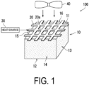
- FIG. 1 is schematic view of the water collecting apparatus 100 according to the first embodiment of the present invention.
- the water collecting apparatus 100 is an apparatus that collects water.
- the water collecting apparatus 100 includes a moisture-absorbing material 10, a heat-conducting member 20, a heat source 30, and an air-blowing unit 40.
- the moisture-absorbing material 10 reversibly absorbs moisture (water vapor) in air and releases the absorbed moisture.
- the moisture-absorbing material 10 includes a predetermined polymer compound having a property in which a degree of hydrophilicity changes with temperature (heat).
- the predetermined polymer compound includes a temperature-responsive polymer having an affinity with water that reversibly changes in response to heat.
- the temperature-responsive polymer is a polymer having a lower critical solution temperature (LCST).
- the temperature-responsive polymer becomes hydrophobic when equal to or greater than the lower critical solution temperature.
- the temperature-responsive polymer becomes hydrophilic at low temperatures less than the lower critical solution temperature.
- the temperature-responsive polymer is a polymer that becomes soluble in water when at low temperatures less than the lower critical solution temperature, but becomes hydrophobic and insoluble when equal to or greater than the lower critical solution temperature.
- the temperature-responsive polymer is more preferably porous, but need not necessarily be porous.
- Examples of the temperature-responsive polymer include: poly(N-alkyl (meth)acrylamide) such as poly(N-isopropyl (meth)acrylamide), poly(N-normalpropyl (meth)acrylamide), poly(N-methyl (meth)acrylamide), poly(N-ethyl (meth)acrylamide), poly(N-normalbutyl (meth)acrylamide), poly(N-isobutyl (meth)acrylamide), or poly(N-t-butyl (meth)acrylamide); poly(N-vinyl alkylamide) such as poly(N-vinyl isopropylamide), poly(N-vinyl normalpropylamide), poly(N-vinyl normalbutylamide), poly(N-vinyl isobutylamide), or poly(N-vinyl-t-butylamide); poly(N-vinylpyrrolidone); poly(2-alkyl-2-oxazoline) such as poly(2-ethyl-2-o
- the temperature-responsive polymer may be a cross-linked body of these polymers.
- examples of such a cross-linked body include a polymer obtained by polymerizing, in the presence of a cross-linking agent, a monomer of: N-alkyl (meth)acrylamide such as N-isopropyl (meth)acrylamide, N-normalpropyl (meth)acrylamide, N-methyl (meth)acrylamide, N-ethyl (meth)acrylamide, N-normalbutyl (meth)acrylamide, N-isobutyl (meth)acrylamide, or N-t-butyl (meth)acrylamide; N-vinyl alkylamide such as N-vinyl isopropylamide, N-vinyl normalpropylamide, N-vinyl normal butylamide, N-vinyl isobutylamide, or N-vinyl-t-butylamide;
- cross-linking agent a conventionally known cross-linking agent may be appropriately selected and used, and for example, a cross-linkable monomer having a polymerizable functional group such as ethylene glycol di(meth)acrylate, propylene glycol di(meth)acrylate, N,N'-methylene bis(meth)acrylamide, tolylene diisocyanate, divinylbenzene, or polyethylene glycol di(meth)acrylate; glutaraldehyde; polyhydric alcohol; polyvalent amine; polyvalent carboxylic acid; metal ions such as calcium ions and zinc ions; and the like can be suitably used.
- cross-linking agents may be used alone, or two or more of them may be used in combination.
- the moisture-absorbing material 10 has a first state and a second state.
- the first state is a state in which the affinity of the predetermined polymer compound contained in the moisture-absorbing material 10 and water improves (degree of hydrophilicity improves), making moisture absorbable by the moisture-absorbing material 10.
- the moisture-absorbing material 10 in the first state swells when absorbing moisture, and thus more readily contains moisture.
- the second state is a state in which the affinity of the predetermined polymer compound contained in the moisture-absorbing material 10 and water deteriorates (degree of hydrophilicity deteriorates), resulting in the release of moisture from the moisture-absorbing material 10.
- the moisture-absorbing material 10 in the second state contracts, and thus less likely retains moisture.
- the moisture-absorbing material 10 is in the first state in a case in which the temperature of the moisture-absorbing material 10 is less than the lower critical solution temperature (about 40°C, for example), and is in the second state in a case in which the temperature of the moisture-absorbing material 10 is equal to or greater than the lower critical solution temperature.
- the moisture-absorbing material 10 is configured to be in the first state at ambient temperature (a state in which atmospheric temperature is a standard temperature), and to be in the second state when heated from this state.
- the moisture-absorbing material 10 when the moisture-absorbing material 10 changes from the first state to the second state (transitions between phases), the moisture-absorbing material 10 is heated to a predetermined heating temperature.
- the predetermined heating temperature is a temperature (from 40°C to less than 80°C, for example) at which the state of the moisture-absorbing material 10 is maintained in the second state and a large portion of the moisture contained in the moisture-absorbing material 10 does not become water vapor in a short time and is maintained in a liquid state. As a result, the moisture contained in the moisture-absorbing material 10 is released from the moisture-absorbing material 10 in a liquid state.
- the moisture-absorbing material 10 is formed in a substantially prismatic shape.
- An outer surface of the moisture-absorbing material 10 includes a first surface 11, a second surface 12, a third surface 13, a fourth surface 14, a fifth surface 15, and a sixth surface 16.
- the first surface 11 constitutes a ceiling surface of the moisture-absorbing material 10.
- the second surface 12 constitutes a bottom surface of the moisture-absorbing material 10 and faces the first surface 11.
- the third surface 13 to the sixth surface 16 are positioned between the first surface 11 and the second surface 12.
- the third surface 13 and the fifth surface 15 constitute side surfaces of the moisture-absorbing material 10, and face each other.
- the fourth surface 14 constitutes a front surface of the moisture-absorbing material 10, and the sixth surface 16 constitutes a back surface of the moisture-absorbing material 10.
- the fourth surface 14 and the sixth surface 16 face each other.
- a shape of the moisture-absorbing material 10 is not particularly limited.
- the heat-conducting member 20 has thermal conductivity.
- the heat-conducting member 20 is formed of, for example, a metal.
- the heat-conducting member 20 is formed in a mesh shape.
- the heat-conducting member 20 includes a through-hole 20a passing through the heat-conducting member 20.
- the heat-conducting member 20 is disposed facing a portion of the outer surface of the moisture-absorbing material 10.
- “Disposed facing” includes not only the heat-conducting member 20 being in contact with a portion of the outer surface of the moisture-absorbing material 10, but also the heat-conducting member 20 being disposed at a predetermined interval from a portion of the outer surface of the moisture-absorbing material 10. The predetermined interval is a distance at which the heat emitted from the heat-conducting member 20 is transmitted to the moisture-absorbing material 10. Further, the heat-conducting member 20 is not disposed facing another portion of the outer surface of the moisture-absorbing material 10, and is disposed so that the other portion of the outer surface of the moisture-absorbing material 10 is left exposed.
- the heat-conducting member 20 is disposed facing the first surface 11 of the moisture-absorbing material 10. Further, in the first embodiment, on the outer surface of the moisture-absorbing material 10, the first surface 11, which is the surface (portion of the outer surface) facing the heat-conducting member 20, and the second surface 12, which is the surface (other portion of the outer surface) not facing the heat-conducting member 20 and thus left exposed, are disposed back to back and positioned collinearly.
- the heat source 30 heats the heat-conducting member 20.
- the heat source 30 includes, for example, a heater. Note that the configuration of the heat source 30 is not particularly limited.
- the heat source 30 may heat the heat-conducting member 20 by flowing current through the heat-conducting member 20 without using a heater.
- the air-blowing unit 40 applies an air current to the moisture-absorbing material 10.
- the air-blowing unit 40 includes, for example, an air-blowing fan and a power source (motor, for example) that rotates the air-blowing fan.
- the air-blowing fan of the air-blowing unit 40 is disposed facing the heat-conducting member 20, and is configured to apply the air current to the moisture-absorbing material 10 through the through-hole 20a of the heat-conducting member 20.
- the heater that is the heat source 30 may be disposed between the air-blowing unit 40 (air-blowing fan) and the heat-conducting member 20, and may be configured so that the air current from the air-blowing unit 40 flows in the order of the heater, the heat-conducting member 20, and the moisture-absorbing material 10.
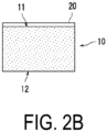
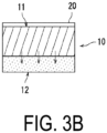
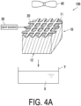
- FIG. 2A to FIG. 4A are schematic views illustrating the operation of the water collecting apparatus 100.
- FIG. 2B to FIG. 4B are schematic views illustrating operation of the moisture-absorbing material 10. Note that, in FIG. 1 to FIG. 7B , the moisture-absorbing material 10 in the first state is denoted by dot hatching, and the moisture-absorbing material 10 in the second state is denoted by diagonal lines.
- the moisture-absorbing material 10 in a stage before the heat source 30 heats the heat-conducting member 20, the moisture-absorbing material 10 is in the first state. That is, the moisture-absorbing material 10 is in a state of high hydrophilicity, and in a state in which moisture is readily absorbed.
- the air current is applied to the moisture-absorbing material 10 by the air-blowing unit 40. As a result, moisture in the air can be effectively absorbed by the moisture-absorbing material 10.
- the heat-conducting member 20 is heated by the heat source 30.
- the heat-conducting member 20 is heated, thereby transmitting the heat of the heat-conducting member 20 to the moisture-absorbing material 10.
- the heat-conducting member 20 heats the moisture-absorbing material 10 to a predetermined heating temperature (from 40°C to less than 80°C, for example).
- a predetermined heating temperature from 40°C to less than 80°C, for example.
- the heat from the heat-conducting member 20 is gradually transmitted from the first surface 11 of the moisture-absorbing material 10 (surface of the moisture-absorbing material 10 on the side facing the heat-conducting member 20) toward the second surface 12 (surface of the moisture-absorbing material 10 on the side not facing the heat-conducting member 20).
- the temperature of the first surface 11 side of the moisture-absorbing material 10 rises to the predetermined heating temperature.
- a region of the moisture-absorbing material 10 in which the temperature rises to the predetermined heating temperature gradually increases from the first surface 11 side toward the second surface 12 side. In this way, the moisture-absorbing material 10 gradually changes from the first state to the second state from the first surface 11 side toward the second surface 12 side.
- the moisture-absorbing material 10 gradually changes from a state of high hydrophilicity to a state of low hydrophilicity from the first surface 11 side toward the second surface 12 side. Furthermore, the moisture-absorbing material 10 contracts when changing from the first state to the second state. As a result, in the moisture-absorbing material 10, the first surface 11 side becomes a skin layer (wall) that prevents a migration of water, and a region of the skin layer gradually expands toward the second surface 12 side, causing the moisture present on the first surface 11 side to migrate toward the second surface 12 side.
- the heat-conducting member 20 is further heated by the heat source 30, causing the region of the moisture-absorbing material 10 that is in the second state (region of the skin layer) to expand to the second surface 12 side. That is, the region having low hydrophilicity expands to the second surface 12 side.
- the moisture contained in the moisture-absorbing material 10 is driven to the second surface 12 side of the moisture-absorbing material 10, advancing the collection of moisture.
- the moisture exudes from the second surface 12 as water droplets and is squeezed out and released from the second surface 12 to outside the moisture-absorbing material 10.
- Moisture X released from the second surface 12 of the moisture-absorbing material 10 is, for example, accommodated in a container Y disposed below the second surface 12.
- the heat-conducting member 20 is disposed facing a portion (first surface 11) of the outer surface of the moisture-absorbing material 10.
- the heat-conducting member 20 is heated, thereby heating the moisture-absorbing material 10 from the first surface 11 side and releasing the moisture from the second surface 12 (refer to FIG. 4A and FIG. 4B ).
- the moisture can be released from the moisture-absorbing material 10 in a state in which the positions of each of the moisture-absorbing material 10 and the heat-conducting member 20 are fixed without moving the moisture-absorbing material 10 and the heat-conducting member 20.
- the apparatus configuration of the water collecting apparatus 100 can be simplified, making it possible to collect moisture using a simple configuration.
- the air current from the air-blowing unit 40 can be applied across the heat-conducting member 20 to the moisture-absorbing material 10 through the through-hole 20a.
- the heat-conducting member 20 and the air-blowing unit 40 air-blowing fan
- the heat-conducting member 20 and the air-blowing unit 40 can be installed on the same side with respect to the moisture-absorbing material 10, making it possible to compactly configure the water collecting apparatus 100.
- the moisture-absorbing material 10 can be phase-transferred by the heating temperature of from 40°C to less than 80°C. Accordingly, the water absorbed by the moisture-absorbing material 10 can be released from the moisture-absorbing material 10 at a low temperature compared to that of zeolite, silica gel, or the like. For example, a temperature of 200°C or higher is required to release the water absorbed by zeolite from zeolite.
- a material of the heat-conducting member 20 is not particularly limited as long as a material has high thermal conductivity.
- the heat-conducting member 20 may be formed of a resin having high thermal conductivity.
- an orientation of the surface that releases the water (second surface 12) is downward, but the orientation of the surface that releases the water (second surface 12) is not limited to downward because the change from the first state to the second state of the moisture-absorbing material 10 is a driving force for water release. That is, the orientation of the surface that releases water (second surface 12) is not limited to the direction of gravity.
- the orientation of the surface that releases the water (second surface 12) may be upward or may be transverse.
- the orientation of the surface that releases the water (second surface 12) is downward or transverse.
- FIG. 5 is a schematic view of the water collecting apparatus 200 according to the second embodiment of the present invention.
- the water collecting apparatus 200 includes the moisture-absorbing material 10, a heat-conducting member 21, the heat source 30 (not illustrated), and the air-blowing unit 40 (not illustrated).
- the heat-conducting member 21 is a first modified example of the heat-conducting member 20 (refer to FIG. 1 ) of the first embodiment.
- the heat-conducting member 21 includes a plurality of through-holes 21a passing through the heat-conducting member 21.
- the heat-conducting member 21 has thermal conductivity and is formed of, for example, a metal.
- the heat-conducting member 21 is manufactured by, for example, forming the plurality of through-holes 21a on a plate-shaped base material.
- the heat-conducting member 21 is, for example, a punched metal.
- the heat-conducting member 21 is disposed facing a portion (first surface 11) of the outer surface of the moisture-absorbing material 10.
- a shape of the through-hole 21a is not particularly limited.
- the shape of the through-hole 21a can be, for example, a circular shape, an elliptical shape, an oblong hole shape, or a linear shape.
- the shape of the through-hole 21a may be a polygonal shape or may be a complex shape such as a star shape, for example.
- the air current from the air-blowing unit 40 is applied to the moisture-absorbing material 10 through the through-holes 21a.
- the moisture-absorbing material 10 in the first state can effectively absorb the moisture in the air.
- the heat-conducting member 21 is heated by the heat source 30 in a state in which the moisture-absorbing material 10 in the first state contains moisture. At this time, the temperature of the moisture-absorbing material 10 gradually rises to the predetermined heating temperature from the first surface 11 side toward the second surface 12 side. Thus, in the moisture-absorbing material 10, moisture present on the first surface 11 side of the moisture-absorbing material 10 migrates to the second surface 12 side, and is released from the second surface 12 to outside the moisture-absorbing material 10 (refer to FIG. 4A and FIG. 4B ).
- the material of the heat-conducting member 21 is not particularly limited as long as a material has high thermal conductivity.
- the heat-conducting member 21 may be formed of a resin having high thermal conductivity.
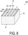
- FIG. 6 is a schematic view of the water collecting apparatus 300 according to the third embodiment of the present invention.
- the water collecting apparatus 300 includes the moisture-absorbing material 10, a heat-conducting member 22, the heat source 30 (not illustrated), and the air-blowing unit 40 (not illustrated).
- the heat-conducting member 22 is a second modified example of the heat-conducting member 20 (refer to FIG. 1 ) of the first embodiment.
- the heat-conducting member 22 has thermal conductivity and is formed of, for example, a metal.
- the heat-conducting member 22 includes a plurality of metal plates 221.
- the plurality of metal plates 221 are disposed in parallel with each other at an interval 22a, and are disposed facing a portion (first surface 11) of the outer surface of the moisture-absorbing material 10.
- the air current from the air-blowing unit 40 is applied to the moisture-absorbing material 10 through the interval 22a portions of the plurality of metal plates 221.
- the moisture-absorbing material 10 in the first state can effectively absorb the moisture in the air.
- the heat-conducting member 22 (plurality of metal plates 221) is heated by the heat source 30 in a state in which the moisture-absorbing material 10 in the first state contains moisture. As a result, the moisture contained in the moisture-absorbing material 10 is released from the second surface 12 to outside the moisture-absorbing material 10 (refer to FIG. 4A and FIG. 4B ).
- the material of the heat-conducting member 22 is not particularly limited as long as a material has high thermal conductivity.
- the heat-conducting member 22 may be formed of a resin having high thermal conductivity.
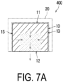
- FIG. 7A is a schematic view of the water collecting apparatus 400 according to the fourth embodiment of the present invention.
- the water collecting apparatus 400 includes the moisture-absorbing material 10, the heat-conducting member 20 (refer to FIG. 1 ), the heat source 30 (not illustrated), and the air-blowing unit 40 (not illustrated).
- the heat-conducting member 20 is disposed facing, of the first surface 11 to the sixth surface 16 (refer to FIG. 1 ) of the outer surface of the moisture-absorbing material 10, the first surface 11 and the third surface 13 to the sixth surface 16. That is, the heat-conducting member 20 faces, of the outer surface of the moisture-absorbing material 10, the surfaces other than the second surface 12.
- the heat-conducting member 20 is heated by the heat source 30, gradually changing the state of the moisture-absorbing material 10 from the first state to the second state, from the first surface 11 side and the surface sides of each of the third surface 13 to the sixth surface 16 of the moisture-absorbing material 10 toward an inner side of the moisture-absorbing material 10.
- moisture contained in the moisture-absorbing material 10 migrates to the inner side of the moisture-absorbing material 10, and is collected from a center portion to a lower portion of the moisture-absorbing material 10, promoting an uneven distribution of moisture inside the moisture-absorbing material 10.
- the collection of moisture toward a center portion of the second surface 12 proceeds and, as a result, water is released from the second surface 12 to outside the moisture-absorbing material 10.
- the heat-conducting member 21 (refer to FIG. 5 ) or the heat-conducting member 22 (refer to FIG. 6 ) may be used instead of the heat-conducting member 20.
- the orientation of the second surface 12 is downward (direction of gravity), but as described in the first embodiment, the orientation of the second surface 12 is not limited to downward (direction of gravity).
- FIG. 7B is a schematic view illustrating a modified example of the water collecting apparatus 400 according to the fourth embodiment of the present invention.
- the moisture-absorbing material 10 may be formed in a frustum shape such as a truncated conical shape or a truncated pyramid shape, for example. With the moisture-absorbing material 10 having a frustum shape, a recovery capacity of the water absorbed can be increased.
- the transfer of heat to the center portion of the moisture-absorbing material 10 is increasingly slower in regions closer to the second surface 12 of the moisture-absorbing material 10 in comparison to a case in which the moisture-absorbing material 10 has a prismatic shape. Accordingly, the closer the region is to the second surface 12, the slower the change to the second state in the center portion of the moisture-absorbing material 10. As a result, the change to the second state (hydrophobization) in the center portion of the second surface 12 is slower than in other portions, and the hydrophilicity is maintained to the end. Accordingly, the moisture migrates from other portions to the center portion of the second surface 12, and collects in the center portion of the second surface 12. Further, the center portion of the second surface 12 functions as a water guide path, facilitating the release of water to outside the moisture-absorbing material 10.
- the moisture-absorbing material 10 has a frustum shape, it is possible to adjust the amount of released water when the water is released from the second surface 12 to outside the moisture-absorbing material 10 by adjusting an expanse of the frustum. In other words, the moisture-absorbing material 10 can be caused to function as a tap.
- FIG. 8 is a schematic view of the water collecting apparatus 500 according to the fifth embodiment of the present invention.
- the water collecting apparatus 500 includes the moisture-absorbing material 10, the heat-conducting member 20 (refer to FIG. 1 ), the heat source 30 (not illustrated), and the air-blowing unit 40 (not illustrated).
- the heat-conducting member 20 is disposed facing the first surface 11 and the third surface 13 to the sixth surface 16 of the moisture-absorbing material 10.
- the first surface 11 and the third surface 13 to the sixth surface 16 are examples of a facing surface of the present invention.
- the second surface 12 is an example of a non-facing surface of the present invention.
- the moisture-absorbing material 10 includes a plurality of layers.
- the plurality of layers are layered from the first surface 11 side toward the second surface 12 side.
- the moisture-absorbing material 10 includes a first layer 10A, a second layer 10B, and a third layer 10C.
- the first layer 10A to the third layer 10C are layered in the order of the first layer 10A, the second layer 10B, and the third layer 10C from the first surface 11 side to the second surface 12 side of the moisture-absorbing material 10.
- the first surface 11 is formed in the first layer 10A.
- the second surface 12 is formed in the third layer 10C.
- the third layer 10C is disposed closer to the second surface 12 (non-facing surface) than the first layer 10A is.
- the first layer 10A is an example of a first layer of the present invention.
- the third layer 10C is an example of a second layer of the present invention.
- the temperatures (lower critical solution temperatures) at which the first layer 10A to the third layer 10C change from the first state to the second state increase in the order of the first layer 10A, the second layer 10B, and the third layer 10C. That is, the moisture-absorbing material 10 has a lower critical solution temperature that increases toward the lower side. Accordingly, the first layer 10A, the second layer 10B, and the third layer 10C become increasingly hydrophilic and more readily absorb moisture in this order.
- the lower critical solution temperature of the first layer 10A is 40°C
- the lower critical solution temperature of the second layer 10B is 45°C
- the lower critical solution temperature of the third layer 10C is 50°C.
- a lower limit of the temperature at which the state changes from the first state to the second state is an example of the temperature at which the degree of hydrophilicity of the polymer compound of the present invention becomes lower than a predetermined standard.
- a total value of the surface areas of all pores desirably decreases in the order of the first layer 10A, the second layer 10B, and the third layer 10C.
- a size of the pores of the first layer 10A to the third layer 10C may decrease in the order of the first layer 10A, the second layer 10B, and the third layer 10C.
- the number of the pores and the size of the pores of the first layer 10A to the third layer 10C decrease in the order of the first layer 10A, the second layer 10B, and the third layer 10C.
- the moisture-absorbing material 10 is increasingly hydrophilic and more readily absorbs moisture as the temperature at which the state changes from the first state to the second state (lower critical solution temperature) increases. Accordingly, when heat is transmitted, moisture is first released from a layer having a low lower critical solution temperature, and the water migrates from the layer having the low lower critical solution temperature to an adjacent layer (layer having a higher lower critical solution temperature and a higher hydrophilicity). For example, water migrates from the first layer 10A to the second layer 10B. Thus, a difference in the lower critical solution temperature or a gradient of the lower critical solution temperature makes it possible to strongly promote water migration associated with heat transfer and prevent a backflow of water.
- the smaller the surface area the smaller the evaporation loss.
- the smaller the surface area the more readily the moisture-absorbing material 10 releases moisture as liquid water when the state transitions to the second state.
- the moisture contained in the moisture-absorbing material 10 can be caused to migrate effectively from the first layer 10A through the second layer 10B, and to the third layer 10C as liquid water when the moisture-absorbing material 10 is heated to the predetermined heating temperature to release the moisture from the moisture-absorbing material 10.
- the moisture collected in the third layer 10C can be effectively released as liquid water from the second surface 12 of the third layer 10C to outside the moisture-absorbing material 10 (refer to FIG. 4A and FIG. 4B ).
- the moisture-absorbing material 10 the larger the surface area of the moisture-absorbing material 10, the higher the evaporation loss during heating and dehydration, but the more readily the moisture-absorbing material 10 absorbs gas and liquid moisture during moisture absorption and water absorption.
- the moisture-absorbing material 10 more readily absorbs moisture in the first layer 10A during the absorption of moisture (water vapor) in the air.
- the temperature at which the heat-conducting member 20 is heated may be gradually increased from a temperature near the lower critical solution temperature of the first layer 10A to a temperature greater than or equal to the lower critical solution temperature of the third layer 10C. This makes it possible to reduce the moisture that is lost by evaporation and cannot be collected from the moisture-absorbing material 10 (evaporation loss). In other words, a collection efficiency of liquid water can be further improved.
- the speed of increasing the temperature at which the heat-conducting member 20 is heated is determined by a thickness of the moisture-absorbing material 10, a composition of the moisture-absorbing material 10, the number of pores, a ratio of a volume occupied by the pores to a volume occupied by a bulk portion, and the like.
- the heat-conducting member 20 may be disposed facing only the first surface 11 as illustrated in FIG. 1 without facing the third surface 13 to the sixth surface 16.
- the heat-conducting member 21 (refer to FIG. 5 ) or the heat-conducting member 22 (refer to FIG. 6 ) may be used instead of the heat-conducting member 20.
- the moisture-absorbing material 10 may have a frustum shape. With the moisture-absorbing material 10 having a frustum shape, the recovery capacity of the water absorbed can be increased.
- the moisture-absorbing material 10 includes three layers (first layer 10A to third layer 10C), but the moisture-absorbing material 10 may include two layers, or may include four or more layers.
- the moisture-absorbing material 10 includes a plurality of layers, but the moisture-absorbing material 10 may be configured so that the lower critical solution temperature is gradually changed from the first surface 11 to the second surface 12. The hydrophilicity changes when the lower critical solution temperature changes.
- the moisture-absorbing material 10 may be configured so that the lower critical solution temperature increases as the distance to the second surface 12 decreases. According to this configuration, by controlling the degree of change in the lower critical solution temperature from the first surface 11 to the second surface 12, water migration and water collection can be promoted and an amount of moisture released from the second surface 12 per unit time and a rate at which moisture is released from the second surface 12 can be controlled. Furthermore, with this configuration as well, by gradually increasing the temperature at which the heat-conducting member 20 is heated, the evaporation loss can be reduced to further improve the collection efficiency of the liquid water.
- the moisture-absorbing material 10 may be configured so that the surface area decreases as the distance to the second surface 12 decreases. According to this configuration, by controlling a degree of change in the surface area from the first surface 11 to the second surface 12, the absorption of moisture from the first surface 11 can be facilitated and the release of liquid water from the second surface 12 can be facilitated. Additionally, this makes it possible to control the amount of moisture released from the second surface 12 per unit time and the rate at which moisture is released from the second surface 12.
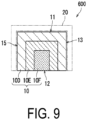
- FIG. 9 is a schematic view of the water collecting apparatus 600 according to the sixth embodiment of the present invention.
- the water collecting apparatus 600 includes the moisture-absorbing material 10, the heat-conducting member 20 (refer to FIG. 1 ), the heat source 30 (not illustrated), and the air-blowing unit 40 (not illustrated).
- the heat-conducting member 20 is disposed facing the first surface 11 and the third surface 13 to the sixth surface 16 of the moisture-absorbing material 10.
- first surface 11 and the third surface 13 to the sixth surface 16 may collectively be referred to as facing surfaces.
- the moisture-absorbing material 10 includes a plurality of layers.
- the moisture-absorbing material 10 includes a fourth layer 10D, a fifth layer 10E, and a sixth layer 10F.
- the fourth layer 10D is positioned on an outermost side
- the fifth layer 10E is positioned inward of the fourth layer 10D
- the sixth layer 10F is positioned inward of the fifth layer 10E.
- the facing surfaces first surface 11 and third surface 13 to sixth surface 16 facing the heat-conducting member 20 are formed.
- the sixth layer 10F the second surface 12 is formed.
- the sixth layer 10F is disposed in a location more spaced apart from the facing surfaces (first surface 11 and third surface 13 to sixth surface 16) than the fourth layer 10D.
- the fourth layer 10D is an example of the first layer of the present invention.
- the sixth layer 10F is an example of the second layer of the present invention.
- the fourth layer 10D to the sixth layer 10F increase in lower critical solution temperature in the order of the fourth layer 10D, the fifth layer 10E, and the sixth layer 10F. Accordingly, the moisture-absorbing material 10 has a lower critical solution temperature that increases inwardly.
- the moisture-absorbing material 10 is heated to the predetermined heating temperature to release moisture from the moisture-absorbing material 10
- the moisture contained in the moisture-absorbing material 10 can be caused to migrate effectively from the fourth layer 10D, through the fifth layer 10E, and to the sixth layer 10F as liquid water.
- the moisture collected in the sixth layer 10F (layer having the highest hydrophilicity) can be effectively released as liquid water from the second surface 12 of the sixth layer 10F to outside the moisture-absorbing material 10 (refer to FIG. 4A and FIG.
- the moisture-absorbing material 10 is porous, increasing the surface area (total value of the surface areas of all pores) from the sixth layer 10F of an innermost shell toward the fourth layer 10D of an outermost shell improves a moisture absorption rate, making it possible to optimize a moisture absorbability and a dehydrability of the moisture-absorbing material 10.
- the temperature at which the heat-conducting member 20 is heated may be gradually increased from a temperature near the lower critical solution temperature of the fourth layer 10D to a temperature greater than or equal to the lower critical solution temperature of the sixth layer 10F. As a result, the evaporation loss can be reduced, and the collection efficiency of the liquid water can be further improved.
- the heat-conducting member 21 (refer to FIG. 5 ) or the heat-conducting member 22 (refer to FIG. 6 ) may be used instead of the heat-conducting member 20.
- the moisture-absorbing material 10 may have a frustum shape. With the moisture-absorbing material 10 having a frustum shape, the recovery capacity of the water absorbed can be increased.
- the moisture-absorbing material 10 includes three layers (fourth layer 10D to sixth layer 10F), but the moisture-absorbing material 10 may include two layers, or may include four or more layers.
- the moisture-absorbing material 10 includes a plurality of layers, but the moisture-absorbing material 10 may be configured so that the lower critical solution temperature increases as a distance to a center portion of the second surface 12 decreases. According to this configuration, by controlling the degree of change in the lower critical solution temperature from the facing surfaces (first surface 11 and third surface 13 to sixth surface 16) to the center portion of the second surface 12, it is possible to control the amount of moisture released from the center portion of the second surface 12 per unit time and the rate at which moisture is released from the center portion of the second surface 12.
- the moisture-absorbing material 10 may be configured so that the surface area (total value of the surface areas of the pores) gradually changes from the facing surfaces (first surface 11 and third surface 13 to sixth surface 16) to the center portion of the second surface 12.
- the moisture-absorbing material 10 may be configured so that the surface area decreases as the distance to the center portion of the second surface 12 decreases. According to this configuration, the degree of change in surface area from the facing surfaces (first surface 11 and third surface 13 to sixth surface 16) to the center portion of the second surface 12 is controlled, making it possible to reduce the evaporation loss while improving the moisture-absorption efficiency.
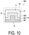
- FIG. 10 is a schematic view of the water collecting apparatus 600 according to another embodiment of the present invention. According to the water collecting apparatus 600 illustrated in FIG. 10 , the evaporation loss from the second surface 12 can be reduced.
- Embodiments of the present invention have been described above with reference to the drawings ( FIG. 1 to FIG. 10 ).
- the present invention is not limited to the embodiments described above, and the present invention can be implemented in various modes ((1) to (7), for example) without departing from the gist thereof.
- the present invention can be made in various forms by appropriately combining a plurality of components disclosed in the embodiments described above. For example, some components may be removed from all of the components described in the embodiments.
- the drawings schematically illustrate the respective main components, and the number of illustrated components, or the like may differ from the actual number of components for the sake of convenience in creating the drawings.
- each of the components described in the above embodiments is exemplary and is not particularly limited, and various modifications can be made within a range that does not substantially depart from the effects of the present invention.
- the moisture-absorbing material 10 having thermal responsiveness includes the photothermal conversion body
- the moisture-absorbing material 10 can be changed from the first state to the second state by irradiating the moisture-absorbing material 10 with light.
- carbon black microparticles can be employed as the photothermal conversion body.
- common metal oxides such as silica, alumina, aluminosilicate, titania, zirconia, and iron oxide, or gold nanoparticles, or the like can be used as the photothermal conversion body.
- the water collecting apparatuses 100, 200, 300, 400, 500, 600 each include a light source such as a lamp, a light-emitting diode (LED), or a laser, for example, instead of the heat source 30 and the heat-conducting members 20, 21, 22.
- a light source such as a lamp, a light-emitting diode (LED), or a laser, for example, instead of the heat source 30 and the heat-conducting members 20, 21, 22.
- the moisture-absorbing material 10 may include the photothermal conversion body only in a portion where light strikes.
- the moisture-absorbing material 10 may be formed so that the photothermal conversion body becomes less in amount as the distance from the portion where light strikes increases. That is, the moisture-absorbing material 10 may be formed so that the photothermal conversion body decreases in density as the distance from the portion where light strikes increases.
- the portion that does not include the photothermal conversion body may include a plurality of layers having thermal responsiveness, as described with reference to FIG. 8 to FIG. 10 , for example.
- the moisture-absorbing material 10 is changed from the first state to the second state by heating the moisture-absorbing material 10, but the moisture-absorbing material 10 may be changed from the first state to the second state by irradiating the moisture-absorbing material 10 with light.
- a moisture-absorbing material having photoresponsiveness may be used as the moisture-absorbing material 10.
- the moisture-absorbing material having photoresponsiveness includes a photoresponsive polymer that reversibly changes an affinity with water in response to light. In a case in which a moisture-absorbing material having photoresponsiveness is used as the moisture-absorbing material 10, the moisture-absorbing material 10 can be changed from the first state to the second state by irradiating the moisture-absorbing material 10 with light.
- the moisture-absorbing material 10 may include a photoresponsive polymer and a temperature-responsive polymer.
- the moisture-absorbing material 10 includes the photoresponsive polymer in the portion where light strikes. The photoresponsive polymer generates heat in response to light. This heat causes the temperature-responsive polymer to change from the first state to the second state.
- the photoresponsive polymer examples include a polymer compound that changes in hydrophilicity or polarity by light, such as azobenzene derivatives, spiropyran derivatives, or the like.
- the photoresponsive moisture-absorbing material may include a cross-linked body of the photoresponsive polymer.
- the photoresponsive moisture-absorbing material may include a copolymer of at least one of a temperature-responsive polymer and a pH-responsive polymer, and a photoresponsive polymer, or a cross-linked body of a copolymer thereof.
- the water collecting apparatuses 100, 200, 300, 400, 500, 600 each include a light source such as a lamp, an LED, or a laser, for example, instead of the heat source 30 and the heat-conducting members 20, 21, 22.
- the moisture-absorbing material 10 may be formed so that the photoresponsiveness decreases as a distance from the portion where light strikes increases. Further, in a case in which the moisture-absorbing material 10 includes a photoresponsive polymer only in the portion where light strikes, the portion that does not include the photoresponsive polymer may include a plurality of layers having thermal responsiveness, as described with reference to FIG. 8 to FIG. 10 , for example.
- the water collecting apparatuses 100, 200, 300, 400, 500, 600 are each configured to include the air-blowing unit 40.
- the air current from the air-blowing unit 40 is applied to the moisture-absorbing material 10 in the first state, making it possible to cause the moisture-absorbing material 10 to effectively absorb the moisture in the air.
- the water collecting apparatuses 100, 200, 300, 400, 500, 600 need not include the air-blowing unit 40. That is, the water collecting apparatus 100, 200, 300, 400, 500, 600 may each be configured so that the moisture-absorbing material 10 in the first state absorbs moisture from the air that naturally comes into contact with the outer surface of the moisture-absorbing material 10. This makes it possible to simplify the apparatus configuration of the water collecting apparatuses 100, 200, 300, 400, 500, 600.
- the application of the water collecting apparatuses 100, 200, 300, 400, 500, 600 is not particularly limited.
- the water collecting apparatuses 100, 200, 300, 400, 500, 600 may each be, for example, used in a dehumidifier, used as a beverage water collecting apparatus that collects beverage water, or as an apparatus for collecting water for applications other than drinking.
- the water collecting apparatuses 100, 200, 300, 400, 500, 600 may each be used as a gardening water collecting apparatus that collects water for gardening.
- the beverage water collecting apparatus may be configured so that a filtration device is separately added and the water collected by the water collecting apparatuses 100, 200, 300, 400, 500, 600 is purified by the filtration device before being provided as beverage water.
- the moisture-absorbing material 10 has a substantially prismatic shape or a frustum shape, but the shape of the moisture-absorbing material 10 is not particularly limited.
- the moisture-absorbing material 10 may have a cylindrical shape, a sheet shape, a particle shape, or a spherical shape.
- a portion of the moisture-absorbing material 10 that releases moisture may have an inclined shape that protrudes while tapered.
- the present invention has applicability in the field of a water collecting apparatus and a water collecting method.
Landscapes
- Chemical & Material Sciences (AREA)
- Analytical Chemistry (AREA)
- Chemical Kinetics & Catalysis (AREA)
- Engineering & Computer Science (AREA)
- Organic Chemistry (AREA)
- General Chemical & Material Sciences (AREA)
- Oil, Petroleum & Natural Gas (AREA)
- Thermal Sciences (AREA)
- Physics & Mathematics (AREA)
- Environmental & Geological Engineering (AREA)
- Health & Medical Sciences (AREA)
- Life Sciences & Earth Sciences (AREA)
- Hydrology & Water Resources (AREA)
- Public Health (AREA)
- Water Supply & Treatment (AREA)
- Solid-Sorbent Or Filter-Aiding Compositions (AREA)
- Drying Of Gases (AREA)
Applications Claiming Priority (2)
| Application Number | Priority Date | Filing Date | Title |
|---|---|---|---|
| JP2020138118 | 2020-08-18 | ||
| PCT/JP2021/030010 WO2022039149A1 (ja) | 2020-08-18 | 2021-08-17 | 水集積装置、及び水集積方法 |
Publications (2)
| Publication Number | Publication Date |
|---|---|
| EP4201505A1 true EP4201505A1 (de) | 2023-06-28 |
| EP4201505A4 EP4201505A4 (de) | 2024-05-22 |
Family
ID=80737823
Family Applications (1)
| Application Number | Title | Priority Date | Filing Date |
|---|---|---|---|
| EP21858293.0A Pending EP4201505A4 (de) | 2020-08-18 | 2021-08-17 | Wassersammelvorrichtung und wassersammelverfahren |
Country Status (4)
| Country | Link |
|---|---|
| US (1) | US12521672B2 (de) |
| EP (1) | EP4201505A4 (de) |
| JP (1) | JP7851063B2 (de) |
| WO (1) | WO2022039149A1 (de) |
Families Citing this family (2)
| Publication number | Priority date | Publication date | Assignee | Title |
|---|---|---|---|---|
| FI130456B (en) | 2022-09-05 | 2023-09-07 | Virte Metalli Oy | System and method for harvesting water from air |
| JP2025067132A (ja) * | 2023-10-12 | 2025-04-24 | 株式会社大気社 | 水分吸脱着器、及び水分吸着材の担持方法 |
Family Cites Families (17)
| Publication number | Priority date | Publication date | Assignee | Title |
|---|---|---|---|---|
| US5534186A (en) * | 1993-12-15 | 1996-07-09 | Gel Sciences, Inc. | Gel-based vapor extractor and methods |
| US20070012186A1 (en) * | 2005-03-11 | 2007-01-18 | Wilson Todd S | System and method of dehumidifying and filtering air |
| NL1030149C1 (nl) * | 2005-10-10 | 2007-04-11 | Eurocore Trading & Consultancy | Werkwijze en inrichting voor het regenereren van een sorptiedroger of -reiniger. |
| US7981199B2 (en) * | 2005-12-19 | 2011-07-19 | Behr Gmbh & Co. Kg | Sorber heat exchanger wall and sorber heat exchanger |
| NL2011443C (en) * | 2013-09-13 | 2015-03-16 | Oxycom Beheer Bv | Water extracting device. |
| MY180007A (en) * | 2013-12-06 | 2020-11-19 | A School Corporation Kansai Univ | Dehumidifier |
| JP6266100B2 (ja) * | 2014-05-09 | 2018-01-24 | シャープ株式会社 | 調湿装置 |
| WO2016035403A1 (ja) * | 2014-09-03 | 2016-03-10 | シャープ株式会社 | 調湿装置 |
| WO2016035409A1 (ja) * | 2014-09-05 | 2016-03-10 | シャープ株式会社 | 調湿装置 |
| JP6439157B2 (ja) * | 2014-10-16 | 2018-12-19 | シャープ株式会社 | 吸湿材、除湿装置及び除湿方法 |
| WO2016068129A1 (ja) | 2014-10-29 | 2016-05-06 | シャープ株式会社 | 吸湿材およびこれを用いた除湿機 |
| JP6528094B2 (ja) | 2015-04-08 | 2019-06-12 | シャープ株式会社 | 水集積装置および水集積方法 |
| NL2016458B1 (en) * | 2016-03-18 | 2017-10-04 | Oxycom Beheer Bv | Smart dehumidifier. |
| WO2019220225A1 (en) * | 2018-05-17 | 2019-11-21 | King Abdullah University Of Science And Technology | Water vapor harvesting materials and devices |
| KR102780674B1 (ko) * | 2018-08-16 | 2025-03-12 | 커먼웰쓰 사이언티픽 앤 인더스트리알 리서치 오거니제이션 | 금속 유기 구조체 기반 물 포획 장치 |
| JP2022552101A (ja) * | 2019-10-17 | 2022-12-15 | ナショナル ユニヴァーシティー オブ シンガポール | 水を捕捉および放出するコンポジット材料 |
| WO2021163290A1 (en) * | 2020-02-14 | 2021-08-19 | The University Of Akron | Freshwater harvesting assembly utilizing water-sorption material within hierarchical component |
-
2021
- 2021-08-17 JP JP2022543948A patent/JP7851063B2/ja active Active
- 2021-08-17 WO PCT/JP2021/030010 patent/WO2022039149A1/ja not_active Ceased
- 2021-08-17 EP EP21858293.0A patent/EP4201505A4/de active Pending
- 2021-08-17 US US18/021,224 patent/US12521672B2/en active Active
Also Published As
| Publication number | Publication date |
|---|---|
| WO2022039149A1 (ja) | 2022-02-24 |
| JP7851063B2 (ja) | 2026-04-24 |
| JPWO2022039149A1 (de) | 2022-02-24 |
| EP4201505A4 (de) | 2024-05-22 |
| US20230294040A1 (en) | 2023-09-21 |
| US12521672B2 (en) | 2026-01-13 |
Similar Documents
| Publication | Publication Date | Title |
|---|---|---|
| US12521672B2 (en) | Water collecting apparatus and water collecting method | |
| CN111278530B (zh) | 气体吸附体和其制造方法及二氧化碳气体浓缩装置 | |
| ES2993713T3 (en) | Apparatus, method and system for direct air capture utilizing electromagnetic excitation radiation desorption of solid amine sorbents to release carbon dioxide | |
| JP4975970B2 (ja) | 収着式熱交換モジュールおよびその製法 | |
| CN107735158B (zh) | 除湿装置以及除湿方法 | |
| JP6889554B2 (ja) | ガス吸収材料、そのガス吸収への使用、ガス吸収体およびガス吸収方法、並びに、酸性ガス吸収装置、酸性ガス回収装置、水蒸気吸収装置、水蒸気回収装置、熱交換器および熱回収装置 | |
| KR101026573B1 (ko) | 흡방습성 초미립자 및 이 초미립자를 이용한 제품 | |
| JP6439157B2 (ja) | 吸湿材、除湿装置及び除湿方法 | |
| JP5962917B2 (ja) | 光熱変換再生デシカントシート、並びに該シートを用いたデシカント素子およびデシカントローター、並びに該素子または該ローターを用いた空調システム | |
| CN106061582B (zh) | 调湿装置 | |
| JP4840685B2 (ja) | 収着式熱交換モジュールおよびその製法 | |
| US20180050298A1 (en) | Water collection device and water collection method | |
| US11383201B2 (en) | Humidity controller | |
| EP3429728B1 (de) | Entfeuchter mit verwendung eines polymers, welches auf einen stimulus reagiert | |
| JP6364618B2 (ja) | 全熱交換素子用仕切部材およびその素材を用いた全熱交換素子および全熱交換形換気装置 | |
| CN107614089A (zh) | 调湿装置 | |
| CN105324625B (zh) | 全热交换元件用分隔部件、使用该部件的全热交换元件和全热交换式换气装置 | |
| WO2021112025A1 (ja) | 除湿装置及び除湿方法 | |
| US20250033334A1 (en) | Liquid-absorbing body and liquid-absorbing device | |
| JP2011202950A (ja) | 収着式熱交換モジュールおよびその製法 | |
| WO2022181741A1 (ja) | 加湿装置 | |
| WO2022176149A1 (ja) | 除湿装置の製造方法、除湿素子及び該除湿素子を備えた除湿装置 |
Legal Events
| Date | Code | Title | Description |
|---|---|---|---|
| STAA | Information on the status of an ep patent application or granted ep patent |
Free format text: STATUS: THE INTERNATIONAL PUBLICATION HAS BEEN MADE |
|
| PUAI | Public reference made under article 153(3) epc to a published international application that has entered the european phase |
Free format text: ORIGINAL CODE: 0009012 |
|
| STAA | Information on the status of an ep patent application or granted ep patent |
Free format text: STATUS: REQUEST FOR EXAMINATION WAS MADE |
|
| 17P | Request for examination filed |
Effective date: 20230307 |
|
| AK | Designated contracting states |
Kind code of ref document: A1 Designated state(s): AL AT BE BG CH CY CZ DE DK EE ES FI FR GB GR HR HU IE IS IT LI LT LU LV MC MK MT NL NO PL PT RO RS SE SI SK SM TR |
|
| DAV | Request for validation of the european patent (deleted) | ||
| DAX | Request for extension of the european patent (deleted) | ||
| RIC1 | Information provided on ipc code assigned before grant |
Ipc: B01J 20/34 20060101ALI20240126BHEP Ipc: B01J 20/28 20060101ALI20240126BHEP Ipc: B01J 20/26 20060101ALI20240126BHEP Ipc: B01D 53/26 20060101AFI20240126BHEP |
|
| A4 | Supplementary search report drawn up and despatched |
Effective date: 20240423 |
|
| RIC1 | Information provided on ipc code assigned before grant |
Ipc: B01J 20/34 20060101ALI20240417BHEP Ipc: B01J 20/28 20060101ALI20240417BHEP Ipc: B01J 20/26 20060101ALI20240417BHEP Ipc: B01D 53/26 20060101AFI20240417BHEP |