EP4201538A1 - Dispositif de nettoyage pour chaîne d'entraînement - Google Patents
Dispositif de nettoyage pour chaîne d'entraînement Download PDFInfo
- Publication number
- EP4201538A1 EP4201538A1 EP22207106.0A EP22207106A EP4201538A1 EP 4201538 A1 EP4201538 A1 EP 4201538A1 EP 22207106 A EP22207106 A EP 22207106A EP 4201538 A1 EP4201538 A1 EP 4201538A1
- Authority
- EP
- European Patent Office
- Prior art keywords
- housing
- cleaning
- cleaning device
- chain
- bicycle chain
- Prior art date
- Legal status (The legal status is an assumption and is not a legal conclusion. Google has not performed a legal analysis and makes no representation as to the accuracy of the status listed.)
- Granted
Links
Images



Classifications
-
- B—PERFORMING OPERATIONS; TRANSPORTING
- B62—LAND VEHICLES FOR TRAVELLING OTHERWISE THAN ON RAILS
- B62J—CYCLE SADDLES OR SEATS; AUXILIARY DEVICES OR ACCESSORIES SPECIALLY ADAPTED TO CYCLES AND NOT OTHERWISE PROVIDED FOR, e.g. ARTICLE CARRIERS OR CYCLE PROTECTORS
- B62J50/00—Arrangements specially adapted for use on cycles not provided for in main groups B62J1/00 - B62J45/00
- B62J50/15—Cleaning devices
- B62J50/16—Cleaning devices for cleaning parts of the cycle, e.g. windscreen wipers
-
- B—PERFORMING OPERATIONS; TRANSPORTING
- B08—CLEANING
- B08B—CLEANING IN GENERAL; PREVENTION OF FOULING IN GENERAL
- B08B1/00—Cleaning by methods involving the use of tools
- B08B1/20—Cleaning of moving articles, e.g. of moving webs or of objects on a conveyor
-
- B—PERFORMING OPERATIONS; TRANSPORTING
- B08—CLEANING
- B08B—CLEANING IN GENERAL; PREVENTION OF FOULING IN GENERAL
- B08B1/00—Cleaning by methods involving the use of tools
- B08B1/30—Cleaning by methods involving the use of tools by movement of cleaning members over a surface
- B08B1/32—Cleaning by methods involving the use of tools by movement of cleaning members over a surface using rotary cleaning members
- B08B1/34—Cleaning by methods involving the use of tools by movement of cleaning members over a surface using rotary cleaning members rotating about an axis parallel to the surface
-
- B—PERFORMING OPERATIONS; TRANSPORTING
- B25—HAND TOOLS; PORTABLE POWER-DRIVEN TOOLS; MANIPULATORS
- B25B—TOOLS OR BENCH DEVICES NOT OTHERWISE PROVIDED FOR, FOR FASTENING, CONNECTING, DISENGAGING, OR HOLDING
- B25B27/00—Hand tools, specially adapted for fitting together or separating parts or objects whether or not involving some deformation, not otherwise provided for
- B25B27/0071—Hand tools, specially adapted for fitting together or separating parts or objects whether or not involving some deformation, not otherwise provided for for bicycles
Definitions
- the invention relates to a cleaning device for a drive chain, in particular a bicycle chain, comprising at least one housing with at least one cleaning brush.
- the adhering dirt including any grease residue
- the repair of a bicycle is not only difficult, but also involves a large number of contaminants, including the hands, for example.
- metal parts or metal abrasion can also stick to a bicycle chain because the bicycle chains are usually covered with a film of grease.
- bicycle chain care In order to avoid premature wear, regular maintenance of the chain is of the utmost importance for every cyclist.
- bicycle chain care also includes greasing the chain and that regular application of a suitable lubricant. Degreasing has the effect of removing the old lubricant and the accumulation of dirt, grit and any metal shavings. If such cleaning is not carried out and a dirty chain is treated with additional lubricants, dirt and grit will only be pressed further into the chain components and wear will be accelerated.
- the bicycle chain grease used can be extremely stubborn and manual cleaning is particularly dirty work, which may also be associated with contamination of the environment, in particular the soil.
- the manual cleaning of the chain is associated with a considerable amount of time, because in most cases the chain is removed and cleaned separately.
- the removal of the bicycle chain and later installation is associated with a considerable amount of time, and not every cyclist is able to do this, for example Reinstall the rear wheel in such a way that the existing components function reliably and have a long service life.
- the present invention is therefore based on the object of demonstrating a cleaning device which enables reliable cleaning of a bicycle chain and also avoids contamination of the environment, in particular of the floor area.
- the at least one cleaning brush is coupled to a sprocket wheel, which can be driven by a moving drive chain.
- the particular advantage of the present cleaning device is that a sprocket wheel is used, which can be driven via the moving drive chain. This can be done, for example, by placing the cleaning device on the bicycle chain and moving the bicycle chain.
- the rear wheel can be raised or the bicycle hung up so that the bicycle chain can run freely without the tires touching the ground.
- degreasing agents or cleaning agents can also be used to remove existing residues from a previous greasing before the chain is greased again.
- the sprocket with a cleaning brush coupled so that when the sprocket wheel moves, the cleaning brush is also rotated.
- the at least one cleaning brush thus rotates and slides along the bicycle chain in order to carry out optimal cleaning.
- the bristles that such a cleaning brush has can not only cover the side area of the bicycle chain, but also the central area, ie the bristles penetrate between the individual segments of a link chain and can remove all adhering dirt.
- the bicycle chain In the case of particularly stubbornly soiled bicycle chains, the bicycle chain must be run through the cleaning device several times so that all adhering dirt particles are removed with certainty.
- the coupling between the sprocket wheel and the cleaning brush has the special advantage that no external drive has to be used to move the bicycle chain. After lifting the rear wheel or hanging up the bicycle, it is sufficient if a pedal is moved manually, which allows the bicycle chain to be pulled through the cleaning device several times.
- the sprocket is set in rotation and transfers this rotation to the cleaning brush, so that the bristles of the cleaning brush can reach every surface of the bicycle chain.
- the sprocket wheel is coupled to at least one further gear wheel which is provided for driving at least one cleaning brush.
- the sprocket wheel is coupled to at least one other gear wheel, preferably also to a plurality of other gear wheels Drive the cleaning brush can be used.
- the at least one gear wheel is coupled to other gear wheels, which are also provided for driving at least one other cleaning brush, so that a multi-stage cleaning process can be carried out using the cleaning brushes.
- the sprocket wheel and the at least one cleaning brush are arranged on a shaft, as a result of which the cleaning brushes are driven directly.
- the driven gear wheels and cleaning brushes are also arranged on a common shaft, so that not only the gear wheels but also the cleaning brushes are driven at the same time via the sprocket wheel.
- the cleaning brushes are optionally designed as gear wheels with spur gear teeth, the spur gear teeth meshing with teeth of the chain gear.
- the sprocket has double toothing, once for the drive chain and once for at least one coupled gear, or that the sprocket and at least one gear are arranged on a common shaft.
- a spur gear toothing is preferably also used in order to transmit the force generated by the bicycle chain via the sprocket to other sprockets.
- the sprocket wheel and at least one other gear wheel are arranged on a common shaft.
- all gears are preferably provided with spur gear teeth in order to form a flat unit of the cleaning device to allow.
- the cleaning device is accommodated in a housing in which the individual gears and the sprocket are rotatably mounted and have a fixed assignment to one another, with the sprocket being directly coupled to another gear, but also an additional indirect coupling from one gear to a next gear is possible.
- the housing is equipped with an entry and exit opening through which the bicycle chain enters the housing.
- the housing In order to place the housing on the bicycle chain, it preferably has a horizontal dividing line so that there are two halves of the housing. The dividing line also runs through the entry and exit opening so that a lower half of the housing can be placed against the bicycle chain and the second upper half of the housing is placed on the first housing part and the bicycle chain thus comes to rest between the two halves of the housing.
- the cleaning process is only started when the two halves of the housing are connected to each other.
- the housing has a clamping bracket for connecting the two halves of the housing.
- Such a clamping bracket can be pivoted laterally to the housing and is rotatably mounted on one housing half, while the clamping bracket clamps the second housing half with a bent free end and thus ensures sufficient tension so that the two housing halves are held together.
- a handle is used and the housing has a recess for an insertable handle.
- the handle can have a one-piece, for example rectangular, end face which fits into a size-matched recess in the two housing halves engages so that the housing can be manually held in a fixed position relative to the bicycle chain using the handle.
- the housing has an opening for supplying a cleaning agent and/or a lubricant.
- an opening is advantageously arranged in the upper edge area of the housing, so that after a first rough cleaning, for example, the cleaning agent can be added, specifically a limited amount, which is collected by the housing. After further cleaning, the cleaning agent including the dirt particles collects in the lower area of the housing and can be disposed of at a later point in time.
- a lubricant for example grease
- the housing halves After the bicycle chain has been cleaned, it is possible to add a lubricant, for example grease, through the same opening to lubricate the chain evenly before the housing is divided into two halves by opening the clamping bracket, in order to clean the housing halves on the one hand, but also the To allow removal of the housing from the bicycle chain.
- a lubricant for example grease
- the housing can be equipped with an arrangement of cleaning brushes in up to three stages, in order to enable intensive cleaning of the bicycle chain.
- the particular advantage of the present invention is that the cleaning device can be used to optimally clean a bicycle chain of large and fine dirt and, for example, degrease the chain and after all dirt particles and grease residues have been removed, the bicycle chain can then be re-greased. Existing dirt particles and fats can be caught inside the housing, so that there is no environmental pollution, and the cleaning device also enables an operator to clean the bicycle chain without getting his hands dirty himself.
- the cleaning device enables the use of a cleaning brush in a single-stage arrangement, but also a multi-stage arrangement with two or three cleaning stages, all of which are coupled together with a chain wheel, so that the movement of the chain through the housing leads to a rotary movement of all cleaning brushes . It is only through the rotary movement that the bicycle chain is optimally cleaned in the side area and also between the individual links.
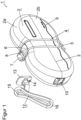
- figure 1 shows a perspective rear view of a cleaning device 1 for a drive chain, for example a bicycle chain.
- the cleaning device has a housing 2, which has the external shape of an eight and consists of two housing halves 2a and 2b.
- the dividing line 3 of the two housing halves 2a, 2b runs along the largest housing dimension.
- the two housing halves 2a and 2b can be joined together via guide elements so that they lie flush on one another.
- the guide elements are, for example, from figure 4 evident.
- the two housing halves 2a, 2b are held together with the aid of a clamping bracket 4, with the clamping bracket 4 being pivotably held in a receptacle 5 in the lower housing half 2b and having corresponding dimensions to the two housing halves 2a, 2b, so that the upper part of the clamping bracket 4 is provided with a Bulge 6 surrounds the upper housing half 2a.
- the clamp 4 consists of two parallel and spaced wire elements which are so stable that the two halves of the housing 2a, 2b are securely pressed together.
- a roller 7 which facilitates the movement of the clamping bracket 4 over the upper housing half 2a by rolling on the housing surface in order to ensure the tension required to hold the two housing halves 2a, 2b together.
- a trough-shaped opening 8 is arranged in the upper area between the two wires of the clamping bracket 4, which opening allows, for example, the addition of a cleaning agent or a means for greasing the chain. If a cleaning agent is added, this happens up to a liquid level of 9, so that the cleaning brushes can be wetted by the cleaning liquid that is present.
- the two housing halves 2a, 2b also have an inlet opening 10 and an outlet opening 11, which cannot be seen in this view, and which allows a bicycle chain to pass through.
- the clamping bracket 4 is removed from the housing 2 so that the two housing halves 2a, 2b can be pulled apart.
- the upper housing part 2a can be placed on the lower housing part 2b and then the clamping bracket 4 can be moved over the upper housing part 2a with the support of the roller 7 and the force applied, so that the two housing halves 2a and 2b are pressed together.
- the cleaning device 1 is held by a handle 12 which is inserted with a plate-shaped projection 13 into a corresponding recess in the housing 2 .
- the insertion takes place before the bicycle chain is inserted, so that after the two housing halves 2a, 2b have been assembled, the handle 12 is firmly connected to the housing 2.
- the handle 12 snaps into an existing groove of the lower housing part 2b via a locking lug 14, so that a secure hold is ensured and the handle 12 is firmly anchored at the latest after the upper housing part 2a has been put on.
- the shape of the handle 12 also resembles an elongated eight with an upper curve 15 and a lower curve 16.
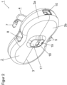
- FIG 2 shows the cleaning device 1 in a further perspective view, this time from the front.
- the cleaning device 1 has the housing 2 with the two housing parts 2a and 2b, a clamping bracket 4 and an inlet opening 10 as well as an outlet opening 11 for the bicycle chain, which cannot be seen from this view.
- the two housing halves 2a, 2b are divided along the dividing line 3 and allow the two housing halves 2a, 2b to be pulled apart after the clamp bracket 4 has been removed, so that the bicycle chain can be inserted.
- the clamping bracket 4 can be guided over the upper housing part 2 using the roller 7 and clamped so that there is a secure hold.
- the handle 12 Before such bracing takes place, the handle 12 is inserted into a bead-shaped elevation 17 with an opening 18 .
- the handle 12 engages with a locking lug 14 in an existing recess 19, so that it is held in the lower housing half 2b and after the upper housing half 2a has been put on, it enables a firm connection to the housing part 2a.
- the mode of operation is such that when the bicycle chain is inserted or the cleaning device 1 is applied to the bicycle chain, the bicycle chain is then manually guided through the housing 2 without an external drive by moving the pedals and can be cleaned with the brushes that cannot be seen from this view.
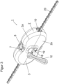
- figure 3 shows the cleaning device 1 again in a perspective view, in this case with an inserted bicycle chain 20 and an inserted handle 12 in the existing recess 18.
- figure 4 shows the opened cleaning device 1 in a perspective view, to the extent that the upper housing half 2a has been lifted off the lower housing half 2b. After the clamp 4 from the top Housing half was removed and thus there is only a pivotable connection with the lower housing half 2b.
- the lower housing half 2b is equipped in the rear area with upward-pointing webs 21 for better merging of the two housing parts 2a and 2b, which engage in corresponding depressions in the upper housing half 2a.
- the sprocket wheel 30 is located on a shaft which carries another gear wheel 31 .
- the sprocket wheel 30 and the gear wheel 31 are manufactured in one piece and are rotatably mounted in the lower housing half 2b via a shaft.
- the gear 31 meshes with two other gears 32, 33.
- the gear wheels 32, 33 are mounted on a shaft (not visible) and are coupled to cleaning brushes 34, 35. The coupling takes place in that the cleaning brushes 34, 35 run synchronously with the gear wheels 32, 33.
- the rotational movement is thus transmitted to the two larger gear wheels 32, 33 via the sprocket wheel 30 and the gear wheel 31, and the cleaning brushes 34, 35 are thus set in motion.
- the cleaning brushes 34, 35 are arranged in pairs on the common shaft so that the side area of both sides of the bicycle chain can be cleaned and also the intermediate area.
- the gears 32, 33 are equipped directly with cleaning bristles.
- the exemplary embodiment thus has two cleaning stages, which can optionally be supplemented by further cleaning stages. This This could be supplemented, for example, by the gears 32, 33 meshing with other gears, which in turn are synchronously coupled to cleaning brushes.
- the particular advantage of the cleaning device 1 is that it has a flat housing shape, which offers the possibility of guiding a bicycle chain through the housing 2 and using the bicycle chain to drive a sprocket 30 at the same time, which in turn is coupled to other gears 32, 33 in order to Drive for the cleaning brushes 34, 35 to realize. While the bicycle chain thus slides through the housing 2, the side area and the intermediate area of the bicycle chain 20 is cleaned using the cleaning brushes 34, 35.
- cleaning fluid can be supplied via the recess 8 in the upper housing half 2a. After the cleaning has taken place, a greasing agent can also be supplied via the recess 8 in order to grease the bicycle chain.
- the particular advantage of the cleaning device 1 is that contamination on the outside, ie on the floor area, is avoided, and the hands of the operator of the cleaning device 1 are also not soiled, so that the entire cleaning process can be regarded as very clean.
- the upper housing part 2a can be removed after loosening the clamping bracket 4 and the lower housing part 2b can then also be removed from the chain.
- the cleaning liquid present in the lower housing part 2b can be poured out in order to be able to put the cleaning device 1 aside for further use.
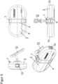
- figure 5 shows the cleaning device 1 in three side views and a perspective view in assembled form with the housing 2 or the two housing parts 2a and 2b, the handle 12 and the clamping bracket 4 and the input opening 10 and output opening 11 for the bicycle chain.
- FIG 6 shows a perspective view of another embodiment of a cleaning device 40 with a housing 41, which also consists of two housing halves 41a and 41b.
- the two housing halves 41a and 41b have a dividing line 42 .
- the housing 41 has an almost square shape with two housing halves 41a, 41b, the upper housing half 41a having a filling opening 43 for a cleaning agent or a lubricant.
- In the lateral face 44 there is an opening 45, which is also present on the opposite side, in order to pass a chain, in particular a bicycle chain.
- a clamping bracket 46 is U-shaped and encloses the two housing halves 41a, 41b, as shown in FIG figure 9 evident.
- clamping bracket 46 With the help of the clamping bracket 46, a compressive stress is built up, which holds the two housing halves 41a, 41b together during the cleaning process.
- clamping bracket 46 In order to ensure that the clamping bracket 46 is held securely, it is equipped with latching recesses 47 which receive the outer edges 48, 49 of the housing 41 in a latching manner.
- figure 7 shows a perspective open view of the cleaning device 40 with an upper housing half 41a and a lower housing half 41b.
- the opening 45 is divided by the parting line 42 so that the upper half case 41a and the lower half cases 41b each have a part of the opening 45 in the form of a U-shaped recess.
- a sprocket wheel 50 which is designed as a double gear wheel and is connected on the one hand to the in figure 9 shown chain meshes and on the other hand has a spur gear teeth, which meshes with at least one gear 51, 52.
- the two gear wheels 51, 52 are each connected to a rotational axis 53, 56 or shaft in a rotationally fixed manner, with a cleaning brush 54, 55 also being located on the rotational axis 53, 56.
- the two gears 51, 52 are driven by the sprocket 50, so that with a Rotation of the gears 51, 52 at the same time the cleaning brushes 54, 55 are rotated and when passing through the bicycle chain this is cleaned both from above and from below.
- the gear wheel 51 is arranged in a raised position above the bicycle chain and the gear wheel 52 is arranged in a lower position below the bicycle chain.
- figure 8 shows a perspective view of the cleaning device 40 with removed gears 51, 52, both of which are arranged on a rotary axis 53, 56.
- a cleaning brush 54, 55 is also located on the axis of rotation 53, 56, so that the bicycle chain can be cleaned from above and below and in the side area.
- the axes of rotation 53, 56 are locked in the housing 40 in receptacles 57 in order to allow a rotational movement when the bicycle chain runs over the chain sprocket 50. In this case, it is a smaller compact cleaning device 40 with a two-stage cleaning.
- FIG 9 shows a perspective view of the cleaning device 40 with a bicycle chain 58.
- the bicycle chain 58 is inserted into the opened housing 41 after the clamping bracket 46 has been removed and the two housing halves 41a and 41b have been separated from one another. After the bicycle chain 58 has been inserted, the two housing parts 41a and 41b are brought together again and the two housing halves 41a and 41b are locked with the aid of the clamping bracket 46 .
- the clamping bracket 46 is also designed as a handle in such a way that the base 59 of the U-shaped clamping bracket 46 is arranged in a raised position relative to the housing 41 so that a palm of the hand can be guided behind the clamping bracket 46 .
- the bicycle chain 58 can be moved through the cleaning device 40 in the usual way using the pedals, for example if the bicycle is hung up or the rear tire is not in contact with the ground.
- figure 10 shows the cleaning device 40 in an assembled form in a total of 6 views, specifically two perspective views and four side views.
Landscapes
- Engineering & Computer Science (AREA)
- Mechanical Engineering (AREA)
- Cleaning In General (AREA)
- Devices For Conveying Motion By Means Of Endless Flexible Members (AREA)
- Vehicle Body Suspensions (AREA)
- Portable Nailing Machines And Staplers (AREA)
- Power-Operated Mechanisms For Wings (AREA)
Applications Claiming Priority (1)
| Application Number | Priority Date | Filing Date | Title |
|---|---|---|---|
| DE202021003846.9U DE202021003846U1 (de) | 2021-12-22 | 2021-12-22 | Reinigungsvorrichtung für eine Antriebskette |
Publications (3)
| Publication Number | Publication Date |
|---|---|
| EP4201538A1 true EP4201538A1 (fr) | 2023-06-28 |
| EP4201538B1 EP4201538B1 (fr) | 2025-04-09 |
| EP4201538C0 EP4201538C0 (fr) | 2025-04-09 |
Family
ID=80267121
Family Applications (1)
| Application Number | Title | Priority Date | Filing Date |
|---|---|---|---|
| EP22207106.0A Active EP4201538B1 (fr) | 2021-12-22 | 2022-11-14 | Dispositif de nettoyage pour chaîne d'entraînement |
Country Status (3)
| Country | Link |
|---|---|
| EP (1) | EP4201538B1 (fr) |
| AU (1) | AU2022283643B2 (fr) |
| DE (2) | DE202021003846U1 (fr) |
Cited By (1)
| Publication number | Priority date | Publication date | Assignee | Title |
|---|---|---|---|---|
| CN119936356A (zh) * | 2025-03-25 | 2025-05-06 | 浙江省林业勘测规划设计有限公司 | 一种湿地资源监测辅助设备 |
Citations (4)
| Publication number | Priority date | Publication date | Assignee | Title |
|---|---|---|---|---|
| NL9000343A (nl) * | 1990-02-13 | 1991-09-02 | Interchain Holland B V | Kettingreiniger. |
| GB2308419A (en) * | 1996-03-02 | 1997-06-25 | Weldtite Prod Ltd | Bicycle chain cleaning apparatus |
| DE202009013659U1 (de) * | 2008-10-31 | 2010-04-08 | Chiu, Fu-Sheng, Hemei | Kettenreinigungsgerät |
| FR3084875A1 (fr) * | 2018-08-08 | 2020-02-14 | Universite D'angers | Dispositif d'entretien d'une chaine a rouleaux de bicyclette |
-
2021
- 2021-12-22 DE DE202021003846.9U patent/DE202021003846U1/de active Active
-
2022
- 2022-11-14 DE DE202022003187.4U patent/DE202022003187U1/de active Active
- 2022-11-14 EP EP22207106.0A patent/EP4201538B1/fr active Active
- 2022-12-06 AU AU2022283643A patent/AU2022283643B2/en active Active
Patent Citations (4)
| Publication number | Priority date | Publication date | Assignee | Title |
|---|---|---|---|---|
| NL9000343A (nl) * | 1990-02-13 | 1991-09-02 | Interchain Holland B V | Kettingreiniger. |
| GB2308419A (en) * | 1996-03-02 | 1997-06-25 | Weldtite Prod Ltd | Bicycle chain cleaning apparatus |
| DE202009013659U1 (de) * | 2008-10-31 | 2010-04-08 | Chiu, Fu-Sheng, Hemei | Kettenreinigungsgerät |
| FR3084875A1 (fr) * | 2018-08-08 | 2020-02-14 | Universite D'angers | Dispositif d'entretien d'une chaine a rouleaux de bicyclette |
Cited By (1)
| Publication number | Priority date | Publication date | Assignee | Title |
|---|---|---|---|---|
| CN119936356A (zh) * | 2025-03-25 | 2025-05-06 | 浙江省林业勘测规划设计有限公司 | 一种湿地资源监测辅助设备 |
Also Published As
| Publication number | Publication date |
|---|---|
| DE202022003187U1 (de) | 2025-07-15 |
| AU2022283643B2 (en) | 2024-07-04 |
| EP4201538B1 (fr) | 2025-04-09 |
| DE202021003846U1 (de) | 2022-01-28 |
| AU2022283643A1 (en) | 2023-07-06 |
| EP4201538C0 (fr) | 2025-04-09 |
Similar Documents
| Publication | Publication Date | Title |
|---|---|---|
| DE2904633C2 (de) | Kehrmaschine | |
| AT406633B (de) | Bodenreinigungsmaschine | |
| DE102011052215A1 (de) | Vorrichtung zum Reinigen von Zweirädern | |
| EP4201538A1 (fr) | Dispositif de nettoyage pour chaîne d'entraînement | |
| DE4426079A1 (de) | Gerät zur Reinigung von Walzen | |
| DE2613149C3 (de) | Vorrichtung zum Reinigen von Förderbändern | |
| DE4437763C2 (de) | Verfahren zur Reinigung von Rolltreppenstufen und Vorrichtung zur Durchführung des Verfahrens | |
| DE1684272B1 (de) | Selbsttaetig arbeitende Reinigungsvorrichtung fuer Gebaeudefassaden und Aussenflaechen von feststehenden Fenstern | |
| EP0160810A1 (fr) | Cabine pour revêtement par poudre | |
| DE102007021255A1 (de) | Spanneinrichtung für Transporteinrichtung | |
| DE102004042708A1 (de) | Handgeführte Kehrwalze | |
| DE3542631C2 (fr) | ||
| EP0105949A2 (fr) | Bicyclette avec arbre d'entraînement | |
| DE102016112624B4 (de) | Eine schwingungsarme Reinigungsvorrichtung für Zwischenräume zwischen Brückenbauteilen | |
| DE3512730A1 (de) | Strassenkehrmaschine | |
| DE10146180B4 (de) | Vorrichtung zur mechanischen Reinigung eines Förderbandes | |
| DE102016112623B4 (de) | Eine mit Kühlungsblättern versehene Reinigungsvorrichtung für Zwischenräume zwischen Brückenbauteilen | |
| EP4159099B1 (fr) | Robot supporté par le sol | |
| DE9215720U1 (de) | Sanitärbürste | |
| DE69311475T2 (de) | Vorrichtung zum Bodenabschaben | |
| DE4416127C1 (de) | Reinigungsvorrichtung für Zylinder einer Druckmaschine | |
| DE4337652C1 (de) | Vorrichtung und Verfahren zum Reinigen mehrwandiger Überlaufrinnen | |
| DE2138194A1 (de) | Reinigungsgeraet fuer die seitenwaende von badebecken | |
| DE131086C (fr) | ||
| AT67529B (de) | Tabak-Entrippmaschine. |
Legal Events
| Date | Code | Title | Description |
|---|---|---|---|
| PUAI | Public reference made under article 153(3) epc to a published international application that has entered the european phase |
Free format text: ORIGINAL CODE: 0009012 |
|
| STAA | Information on the status of an ep patent application or granted ep patent |
Free format text: STATUS: THE APPLICATION HAS BEEN PUBLISHED |
|
| AK | Designated contracting states |
Kind code of ref document: A1 Designated state(s): AL AT BE BG CH CY CZ DE DK EE ES FI FR GB GR HR HU IE IS IT LI LT LU LV MC ME MK MT NL NO PL PT RO RS SE SI SK SM TR |
|
| STAA | Information on the status of an ep patent application or granted ep patent |
Free format text: STATUS: REQUEST FOR EXAMINATION WAS MADE |
|
| 17P | Request for examination filed |
Effective date: 20230925 |
|
| RBV | Designated contracting states (corrected) |
Designated state(s): AL AT BE BG CH CY CZ DE DK EE ES FI FR GB GR HR HU IE IS IT LI LT LU LV MC ME MK MT NL NO PL PT RO RS SE SI SK SM TR |
|
| REG | Reference to a national code |
Ipc: B62J0050160000 Ref country code: DE Ref legal event code: R079 Ref document number: 502022003499 Country of ref document: DE Free format text: PREVIOUS MAIN CLASS: B08B0001020000 Ipc: B62J0050160000 |
|
| RIC1 | Information provided on ipc code assigned before grant |
Ipc: B08B 1/20 20240101ALI20241205BHEP Ipc: B08B 1/34 20240101ALI20241205BHEP Ipc: B25B 27/00 20060101ALI20241205BHEP Ipc: B62J 50/16 20200101AFI20241205BHEP |
|
| GRAP | Despatch of communication of intention to grant a patent |
Free format text: ORIGINAL CODE: EPIDOSNIGR1 |
|
| STAA | Information on the status of an ep patent application or granted ep patent |
Free format text: STATUS: GRANT OF PATENT IS INTENDED |
|
| INTG | Intention to grant announced |
Effective date: 20250120 |
|
| GRAS | Grant fee paid |
Free format text: ORIGINAL CODE: EPIDOSNIGR3 |
|
| GRAA | (expected) grant |
Free format text: ORIGINAL CODE: 0009210 |
|
| STAA | Information on the status of an ep patent application or granted ep patent |
Free format text: STATUS: THE PATENT HAS BEEN GRANTED |
|
| AK | Designated contracting states |
Kind code of ref document: B1 Designated state(s): AL AT BE BG CH CY CZ DE DK EE ES FI FR GB GR HR HU IE IS IT LI LT LU LV MC ME MK MT NL NO PL PT RO RS SE SI SK SM TR |
|
| REG | Reference to a national code |
Ref country code: GB Ref legal event code: FG4D Free format text: NOT ENGLISH |
|
| REG | Reference to a national code |
Ref country code: CH Ref legal event code: EP |
|
| REG | Reference to a national code |
Ref country code: DE Ref legal event code: R096 Ref document number: 502022003499 Country of ref document: DE |
|
| REG | Reference to a national code |
Ref country code: IE Ref legal event code: FG4D Free format text: LANGUAGE OF EP DOCUMENT: GERMAN |
|
| U01 | Request for unitary effect filed |
Effective date: 20250416 |
|
| U07 | Unitary effect registered |
Designated state(s): AT BE BG DE DK EE FI FR IT LT LU LV MT NL PT RO SE SI Effective date: 20250424 |
|
| PG25 | Lapsed in a contracting state [announced via postgrant information from national office to epo] |
Ref country code: ES Free format text: LAPSE BECAUSE OF FAILURE TO SUBMIT A TRANSLATION OF THE DESCRIPTION OR TO PAY THE FEE WITHIN THE PRESCRIBED TIME-LIMIT Effective date: 20250409 |
|
| PG25 | Lapsed in a contracting state [announced via postgrant information from national office to epo] |
Ref country code: NO Free format text: LAPSE BECAUSE OF FAILURE TO SUBMIT A TRANSLATION OF THE DESCRIPTION OR TO PAY THE FEE WITHIN THE PRESCRIBED TIME-LIMIT Effective date: 20250709 Ref country code: GR Free format text: LAPSE BECAUSE OF FAILURE TO SUBMIT A TRANSLATION OF THE DESCRIPTION OR TO PAY THE FEE WITHIN THE PRESCRIBED TIME-LIMIT Effective date: 20250710 |
|
| PG25 | Lapsed in a contracting state [announced via postgrant information from national office to epo] |
Ref country code: PL Free format text: LAPSE BECAUSE OF FAILURE TO SUBMIT A TRANSLATION OF THE DESCRIPTION OR TO PAY THE FEE WITHIN THE PRESCRIBED TIME-LIMIT Effective date: 20250409 |
|
| PG25 | Lapsed in a contracting state [announced via postgrant information from national office to epo] |
Ref country code: HR Free format text: LAPSE BECAUSE OF FAILURE TO SUBMIT A TRANSLATION OF THE DESCRIPTION OR TO PAY THE FEE WITHIN THE PRESCRIBED TIME-LIMIT Effective date: 20250409 |
|
| PG25 | Lapsed in a contracting state [announced via postgrant information from national office to epo] |
Ref country code: RS Free format text: LAPSE BECAUSE OF FAILURE TO SUBMIT A TRANSLATION OF THE DESCRIPTION OR TO PAY THE FEE WITHIN THE PRESCRIBED TIME-LIMIT Effective date: 20250709 |
|
| PG25 | Lapsed in a contracting state [announced via postgrant information from national office to epo] |
Ref country code: IS Free format text: LAPSE BECAUSE OF FAILURE TO SUBMIT A TRANSLATION OF THE DESCRIPTION OR TO PAY THE FEE WITHIN THE PRESCRIBED TIME-LIMIT Effective date: 20250809 |
|
| U20 | Renewal fee for the european patent with unitary effect paid |
Year of fee payment: 4 Effective date: 20250922 |
|
| PG25 | Lapsed in a contracting state [announced via postgrant information from national office to epo] |
Ref country code: SM Free format text: LAPSE BECAUSE OF FAILURE TO SUBMIT A TRANSLATION OF THE DESCRIPTION OR TO PAY THE FEE WITHIN THE PRESCRIBED TIME-LIMIT Effective date: 20250409 |
|
| PG25 | Lapsed in a contracting state [announced via postgrant information from national office to epo] |
Ref country code: CZ Free format text: LAPSE BECAUSE OF FAILURE TO SUBMIT A TRANSLATION OF THE DESCRIPTION OR TO PAY THE FEE WITHIN THE PRESCRIBED TIME-LIMIT Effective date: 20250409 |
|
| PG25 | Lapsed in a contracting state [announced via postgrant information from national office to epo] |
Ref country code: SK Free format text: LAPSE BECAUSE OF FAILURE TO SUBMIT A TRANSLATION OF THE DESCRIPTION OR TO PAY THE FEE WITHIN THE PRESCRIBED TIME-LIMIT Effective date: 20250409 |
|
| PLBE | No opposition filed within time limit |
Free format text: ORIGINAL CODE: 0009261 |
|
| STAA | Information on the status of an ep patent application or granted ep patent |
Free format text: STATUS: NO OPPOSITION FILED WITHIN TIME LIMIT |
|
| REG | Reference to a national code |
Ref country code: CH Ref legal event code: L10 Free format text: ST27 STATUS EVENT CODE: U-0-0-L10-L00 (AS PROVIDED BY THE NATIONAL OFFICE) Effective date: 20260218 |
|
| 26N | No opposition filed |
Effective date: 20260112 |