EP4201552A1 - Appareils, systèmes et procédés de bobinage et de débobinage - Google Patents
Appareils, systèmes et procédés de bobinage et de débobinage Download PDFInfo
- Publication number
- EP4201552A1 EP4201552A1 EP21217624.2A EP21217624A EP4201552A1 EP 4201552 A1 EP4201552 A1 EP 4201552A1 EP 21217624 A EP21217624 A EP 21217624A EP 4201552 A1 EP4201552 A1 EP 4201552A1
- Authority
- EP
- European Patent Office
- Prior art keywords
- filament
- glass
- rod
- laser
- heat source
- Prior art date
- Legal status (The legal status is an assumption and is not a legal conclusion. Google has not performed a legal analysis and makes no representation as to the accuracy of the status listed.)
- Withdrawn
Links
Images

Classifications
-
- B—PERFORMING OPERATIONS; TRANSPORTING
- B22—CASTING; POWDER METALLURGY
- B22F—WORKING METALLIC POWDER; MANUFACTURE OF ARTICLES FROM METALLIC POWDER; MAKING METALLIC POWDER; APPARATUS OR DEVICES SPECIALLY ADAPTED FOR METALLIC POWDER
- B22F10/00—Additive manufacturing of workpieces or articles from metallic powder
- B22F10/10—Formation of a green body
- B22F10/18—Formation of a green body by mixing binder with metal in filament form, e.g. fused filament fabrication [FFF]
-
- B—PERFORMING OPERATIONS; TRANSPORTING
- B21—MECHANICAL METAL-WORKING WITHOUT ESSENTIALLY REMOVING MATERIAL; PUNCHING METAL
- B21C—MANUFACTURE OF METAL SHEETS, WIRE, RODS, TUBES, PROFILES OR LIKE SEMI-MANUFACTURED PRODUCTS OTHERWISE THAN BY ROLLING; AUXILIARY OPERATIONS USED IN CONNECTION WITH METAL-WORKING WITHOUT ESSENTIALLY REMOVING MATERIAL
- B21C47/00—Winding-up, coiling or winding-off metal wire, metal band or other flexible metal material characterised by features relevant to metal processing only
- B21C47/02—Winding-up or coiling
- B21C47/04—Winding-up or coiling on or in reels or drums, without using a moving guide
-
- B—PERFORMING OPERATIONS; TRANSPORTING
- B21—MECHANICAL METAL-WORKING WITHOUT ESSENTIALLY REMOVING MATERIAL; PUNCHING METAL
- B21C—MANUFACTURE OF METAL SHEETS, WIRE, RODS, TUBES, PROFILES OR LIKE SEMI-MANUFACTURED PRODUCTS OTHERWISE THAN BY ROLLING; AUXILIARY OPERATIONS USED IN CONNECTION WITH METAL-WORKING WITHOUT ESSENTIALLY REMOVING MATERIAL
- B21C47/00—Winding-up, coiling or winding-off metal wire, metal band or other flexible metal material characterised by features relevant to metal processing only
- B21C47/16—Unwinding or uncoiling
- B21C47/18—Unwinding or uncoiling from reels or drums
-
- B—PERFORMING OPERATIONS; TRANSPORTING
- B21—MECHANICAL METAL-WORKING WITHOUT ESSENTIALLY REMOVING MATERIAL; PUNCHING METAL
- B21C—MANUFACTURE OF METAL SHEETS, WIRE, RODS, TUBES, PROFILES OR LIKE SEMI-MANUFACTURED PRODUCTS OTHERWISE THAN BY ROLLING; AUXILIARY OPERATIONS USED IN CONNECTION WITH METAL-WORKING WITHOUT ESSENTIALLY REMOVING MATERIAL
- B21C47/00—Winding-up, coiling or winding-off metal wire, metal band or other flexible metal material characterised by features relevant to metal processing only
- B21C47/26—Special arrangements with regard to simultaneous or subsequent treatment of the material
-
- B—PERFORMING OPERATIONS; TRANSPORTING
- B21—MECHANICAL METAL-WORKING WITHOUT ESSENTIALLY REMOVING MATERIAL; PUNCHING METAL
- B21F—WORKING OR PROCESSING OF METAL WIRE
- B21F23/00—Feeding wire in wire-working machines or apparatus
- B21F23/002—Feeding means specially adapted for handling various diameters of wire or rod
-
- B—PERFORMING OPERATIONS; TRANSPORTING
- B22—CASTING; POWDER METALLURGY
- B22F—WORKING METALLIC POWDER; MANUFACTURE OF ARTICLES FROM METALLIC POWDER; MAKING METALLIC POWDER; APPARATUS OR DEVICES SPECIALLY ADAPTED FOR METALLIC POWDER
- B22F10/00—Additive manufacturing of workpieces or articles from metallic powder
- B22F10/80—Data acquisition or data processing
- B22F10/85—Data acquisition or data processing for controlling or regulating additive manufacturing processes
-
- B—PERFORMING OPERATIONS; TRANSPORTING
- B22—CASTING; POWDER METALLURGY
- B22F—WORKING METALLIC POWDER; MANUFACTURE OF ARTICLES FROM METALLIC POWDER; MAKING METALLIC POWDER; APPARATUS OR DEVICES SPECIALLY ADAPTED FOR METALLIC POWDER
- B22F12/00—Apparatus or devices specially adapted for additive manufacturing; Auxiliary means for additive manufacturing; Combinations of additive manufacturing apparatus or devices with other processing apparatus or devices
- B22F12/10—Auxiliary heating means
- B22F12/13—Auxiliary heating means to preheat the material
-
- B—PERFORMING OPERATIONS; TRANSPORTING
- B22—CASTING; POWDER METALLURGY
- B22F—WORKING METALLIC POWDER; MANUFACTURE OF ARTICLES FROM METALLIC POWDER; MAKING METALLIC POWDER; APPARATUS OR DEVICES SPECIALLY ADAPTED FOR METALLIC POWDER
- B22F12/00—Apparatus or devices specially adapted for additive manufacturing; Auxiliary means for additive manufacturing; Combinations of additive manufacturing apparatus or devices with other processing apparatus or devices
- B22F12/50—Means for feeding of material, e.g. heads
- B22F12/53—Nozzles
-
- B—PERFORMING OPERATIONS; TRANSPORTING
- B22—CASTING; POWDER METALLURGY
- B22F—WORKING METALLIC POWDER; MANUFACTURE OF ARTICLES FROM METALLIC POWDER; MAKING METALLIC POWDER; APPARATUS OR DEVICES SPECIALLY ADAPTED FOR METALLIC POWDER
- B22F12/00—Apparatus or devices specially adapted for additive manufacturing; Auxiliary means for additive manufacturing; Combinations of additive manufacturing apparatus or devices with other processing apparatus or devices
- B22F12/90—Means for process control, e.g. cameras or sensors
-
- B—PERFORMING OPERATIONS; TRANSPORTING
- B33—ADDITIVE MANUFACTURING TECHNOLOGY
- B33Y—ADDITIVE MANUFACTURING, i.e. MANUFACTURING OF THREE-DIMENSIONAL [3D] OBJECTS BY ADDITIVE DEPOSITION, ADDITIVE AGGLOMERATION OR ADDITIVE LAYERING, e.g. BY 3D PRINTING, STEREOLITHOGRAPHY OR SELECTIVE LASER SINTERING
- B33Y40/00—Auxiliary operations or equipment, e.g. for material handling
- B33Y40/10—Pre-treatment
-
- B—PERFORMING OPERATIONS; TRANSPORTING
- B33—ADDITIVE MANUFACTURING TECHNOLOGY
- B33Y—ADDITIVE MANUFACTURING, i.e. MANUFACTURING OF THREE-DIMENSIONAL [3D] OBJECTS BY ADDITIVE DEPOSITION, ADDITIVE AGGLOMERATION OR ADDITIVE LAYERING, e.g. BY 3D PRINTING, STEREOLITHOGRAPHY OR SELECTIVE LASER SINTERING
- B33Y70/00—Materials specially adapted for additive manufacturing
-
- C—CHEMISTRY; METALLURGY
- C03—GLASS; MINERAL OR SLAG WOOL
- C03C—CHEMICAL COMPOSITION OF GLASSES, GLAZES OR VITREOUS ENAMELS; SURFACE TREATMENT OF GLASS; SURFACE TREATMENT OF FIBRES OR FILAMENTS MADE FROM GLASS, MINERALS OR SLAGS; JOINING GLASS TO GLASS OR OTHER MATERIALS
- C03C25/00—Surface treatment of fibres or filaments made from glass, minerals or slags
- C03C25/62—Surface treatment of fibres or filaments made from glass, minerals or slags by application of electric or wave energy; by particle radiation or ion implantation
- C03C25/6206—Electromagnetic waves
- C03C25/6208—Laser
-
- C—CHEMISTRY; METALLURGY
- C21—METALLURGY OF IRON
- C21D—MODIFYING THE PHYSICAL STRUCTURE OF FERROUS METALS; GENERAL DEVICES FOR HEAT TREATMENT OF FERROUS OR NON-FERROUS METALS OR ALLOYS; MAKING METAL MALLEABLE, e.g. BY DECARBURISATION OR TEMPERING
- C21D1/00—General methods or devices for heat treatment, e.g. annealing, hardening, quenching or tempering
- C21D1/34—Methods of heating
-
- C—CHEMISTRY; METALLURGY
- C21—METALLURGY OF IRON
- C21D—MODIFYING THE PHYSICAL STRUCTURE OF FERROUS METALS; GENERAL DEVICES FOR HEAT TREATMENT OF FERROUS OR NON-FERROUS METALS OR ALLOYS; MAKING METAL MALLEABLE, e.g. BY DECARBURISATION OR TEMPERING
- C21D11/00—Process control or regulation for heat treatments
-
- C—CHEMISTRY; METALLURGY
- C21—METALLURGY OF IRON
- C21D—MODIFYING THE PHYSICAL STRUCTURE OF FERROUS METALS; GENERAL DEVICES FOR HEAT TREATMENT OF FERROUS OR NON-FERROUS METALS OR ALLOYS; MAKING METAL MALLEABLE, e.g. BY DECARBURISATION OR TEMPERING
- C21D9/00—Heat treatment, e.g. annealing, hardening, quenching or tempering, adapted for particular articles; Furnaces therefor
- C21D9/52—Heat treatment, e.g. annealing, hardening, quenching or tempering, adapted for particular articles; Furnaces therefor for wires; for strips ; for rods of unlimited length
- C21D9/54—Furnaces for treating strips or wire
- C21D9/68—Furnace coilers; Hot coilers
-
- C—CHEMISTRY; METALLURGY
- C21—METALLURGY OF IRON
- C21D—MODIFYING THE PHYSICAL STRUCTURE OF FERROUS METALS; GENERAL DEVICES FOR HEAT TREATMENT OF FERROUS OR NON-FERROUS METALS OR ALLOYS; MAKING METAL MALLEABLE, e.g. BY DECARBURISATION OR TEMPERING
- C21D2221/00—Treating localised areas of an article
Definitions
- the present disclosure relates generally to glass spooling and unspooling systems for use in 3D printing apparatus and to the glass objects produced therefrom. Methods for laser assisted spooling or unspooling of printing materials, such as glass or metal, are also described.
- 3D printing or 'additive manufacturing' refers to processes in which an object is manufactured by adding material sequentially to itself or to another material, typically by laying down successive layers or the material under a computer-controlled process, in order to create often complex 3D structures, according to a 3D model.
- Techniques for 3D printing that have been used in connection with glass and other materials include Fused Deposition Modeling (FDM) and Fused Filament Fabrication (FFF), which rely on melting of a rod or filament of the feedstock material (generally within a 'nozzle') in order to lay down layers of the molten material so as to form a desired three-dimensional shape.
- FDM Fused Deposition Modeling
- FFF Fused Filament Fabrication
- FDM and FFF printing processes generally require a continuous feed of printing material for the duration of a print. If the printing material flow is not continuous, cracks and airgaps may appear in the printed part while printed. Such airgaps prevent the printed part from being sealed against liquid and reduce its strength (e.g. in post-print processing).
- WO2018/163006 A1 describes a 3D extrusion printing system for printing high melting temperature materials such as glass.
- the system comprises a heated chamber, a printing base plate mounted inside the heated chamber, a cooling unit mounted outside the heated chamber and surrounding the printing nozzle, and a nozzle heating unit mounted around the printing nozzle inside the heated chamber.
- the printing material in the form of a rod is intended to be pulled by a feeding mechanism from the upper side of the nozzle and heated while passing through the nozzle.
- WO2018/163007 A1 describes a system for continuous filament feeding in which the end of one rod feedstock of a printing material is bonded to an opposing end of a following rod feedstock in a 'bonding station' so as to provide a continuous feedstock to and from the printing nozzle.
- the printing material - rather than being provided in the form of a rod - may be provided in the form of a spool, which can allow for much larger amounts of printing material and, hence, longer prints, to be used before recharging or changing the feedstock. In this way, any need to join opposing ends of adjacent feedstocks can be obviated or at least minimised.
- a spool of material for printing must be continuously unspooled / unwound during printing.
- this approach may be convenient for certain materials of feedstock, e.g. metals or polymers, which may have good inherent flexibility, especially when in relatively thin filament form, significant challenges can arise when the printing material is relatively inflexible, such as glass. Particularly difficulties exist in how to unwind / unspool the glass printing material for feeding into the printing head at an appropriate rate for printing.
- a system and an apparatus for spooling or unspooling of a filament or rod material such as glass or metal rods / filaments
- the system or apparatus comprising a heat source; and a spooling or rotatable member configured to rotate around its central axis of symmetry.
- the heat source is arranged to deliver heat energy for melting or softening of the filament material adjacent the spooling member (or at least adjacent the growing or decreasing spool of material) so that the filament material is softened sufficiently to allow coiling or uncoiling of the material onto or from the spooling member before solidifying once again.
- the spooling member may be coupled with a motor for causing powered rotation of the spooling / rotating member.
- the filament or rod material is fixed to the rotatable member my any conventional means in the art such as a clamp or glue.
- the filament or rod material may be fixed to the rotatable member by a metal plate preloaded with a spring to secure the first end of the filament or rod material to the rotatable member.
- the heat source is directional or targeted, such that it may not be necessary to heat the environment in which the filament material is present.
- a directional heating source may advantageously be targeted directly towards the filament material / feedstock.
- the heat source is beneficially a laser.
- the heat source may be selected from a plasma torch, a gas torch, an electron beam, an ion beam, an inductively heated metal part and combinations thereof.
- the system or apparatus may further comprise a heat source controller so as to control the activity and power of the heat source.
- the heat source in use, is configured / controlled to provide a continuous source of heat throughout the period during which the filament material is being spooled or unspooled.
- the heat source may be operable to deliver a constant amount of heat energy per unit time, so that the filament is heated uniformly along its length during spooling or unspooling.
- the heat source is controlled according to the desired temperature of the filament material or at least the surface temperature of the material at the target region, to enable optimal and/or the desired rate or spooling or unspooling.
- the heat source controller may comprise a feedback mechanism for adjusting the power or temperature of the heat source according to one or more factors, such as the temperature of the feed stock, the desired temperature of the feed stock, the speed / rate of spooling or unspooling (e.g. the linear speed of movement of the feed stock prior to spooling or after unspooling, or the rotational speed of the spooling or rotating member) or the desired speed / rate of spooling or unspooling, the mass of feedstock to be spooled or unspooled in a particular unit time, the thickness of the filament / rod of feed stock, or the material or composition of the feed stock.
- the speed / rate of spooling or unspooling e.g. the linear speed of movement of the feed stock prior to spooling or after unspooling, or the rotational speed of the spooling or rotating member
- the desired speed / rate of spooling or unspooling e.g. the linear speed of movement of the feed stock prior to spooling
- the system or apparatus may comprise a temperature sensor for monitoring and optionally signaling the temperature of the filament material at the point of softening to the heat source controller in order to control the amount of heat energy delivered to the filament material.
- the heat source e.g. the laser, and the spooling member may be orientated perpendicular to each other or at any other convenient angle, according to preference or requirements.
- the system or apparatus may also comprise a pushing or a pulling mechanism in order to cause the filament feed material to be drawn towards or away from the spooling member at a desired linear rate.
- the pushing or pulling mechanism is directional so as to direct the material to be spooled towards the correct point / region of the spooling member, or to direct the unspooling material towards a desired destination, such as a 3D printing nozzle.
- the pulling mechanism may conveniently be part of a 3D printing apparatus, e.g. associated with a printing nozzle to deliver a desired amount of filament feedstock to the nozzle per unit time for printing.
- the spooling / rotating member is configured to accommodate a spooled material, such as a coiled glass or metal rod.
- the spooling / rotating member may be formed from any suitable material, such as a material from the group consisting of: metals, metal alloys, or polymers. For example, including stainless-steel or metal carbides such as silicon carbide.
- the spooling member is a metal substrate such as a stainless-steel substrate, but a polymer substrate is also envisaged.
- the spooling member comprises a cylindrical body for each of spooling and unspooling, in use.
- the cylindrical body may have any desired diameter and length: for example, according to the size of the apparatus, the thickness of the filament material to be spooled, or depending on the intended diameter of the spooled material.
- a cylindrical substrate allows for the melting position to remain in substantially the same location throughout the spooling or unspooling process.
- the heat source may comprise at least one laser, typically at least one CO 2 laser, although any other convenient or desirable lasers may alternatively be used.
- the laser beam may be split (e.g. with a beam splitter) into two, three or more separate laser beams so as to provide heat energy to more than one location on the target filament.
- the intensity of the laser may be at least about 1 and at most about 10 W/mm 2 , such as between about 2 W/mm 2 and 8 W/mm 2 or between about 3 W/mm 2 and 7 W/mm 2 .
- the laser has an intensity of 4 W/mm 2 , 5 W/mm 2 or 6 W/mm 2 .
- the laser may have a central wavelength of at least about 9 ⁇ m and at most about 12 ⁇ m.
- the laser has a central wavelength of between about 9 ⁇ m and 11 ⁇ m, more suitably between about 9.3 ⁇ m and 10.6 ⁇ m, and most suitably between about 9.6 ⁇ m and 10.6 ⁇ m, such as, 10.3 ⁇ m, 10.4 ⁇ m, 10.5 ⁇ m and most suitably, 10.6 ⁇ m.
- the laser may be a CO 2 laser.
- the laser may have a central wavelength of at least about 3 ⁇ m and at most about 6 ⁇ m, such as between about 4 ⁇ m and about 6 ⁇ m, between about 5 ⁇ m and about 6 ⁇ m, or between about 5.2 ⁇ m and about 6 ⁇ m.
- the laser may have a central wavelength of 5.0 ⁇ m, 5.1 ⁇ m 5.2 ⁇ m, 5.3 ⁇ m, 5.4 ⁇ m or 5.5 ⁇ m.
- the laser may be a CO laser.
- the laser may have a central wavelength of at least about 2 ⁇ m and at most about 4 ⁇ m, such as between about 2 ⁇ m and about 3 ⁇ m, or between about 2.2 ⁇ m and about 2.8 ⁇ m. In embodiments, the laser may have a central wavelength of 2.3 ⁇ m, 2.4 ⁇ m, 2.5 ⁇ m or 2.6 ⁇ m.
- the laser may be a laser diode.
- the system or apparatus may further comprise apparatus for focussing the heat source or laser onto the filament material.
- the means for focussing the heat source or laser onto the filament material may be a mirror or a lens or combinations thereof.
- a plurality of mirrors and/or lenses may be used.
- the system or apparatus may comprise one mirror, two mirrors or three mirrors, depending on the position of the laser source and the location at which the heat energy is to be delivered.
- the system may comprise at least one lens, e.g. one lens, two lenses or three lenses, depending on the position at which it is intended to deliver heat energy to the filament material (relative to the location and orientation of the laser source, and the size (diameter) of the laser beam that is desired to be delivered.
- the diameter of the laser beam will be selected according to the diameter of the filament material to be heated.
- the system or apparatus may further comprise one or more positional adjustment mechanism for adjusting the position, angle and/or orientation of the one or more mirror, one or more lens, or one or more beam splitter.
- the resulting temperature at the surface of the glass rod is determined by speed, laser intensity and wavelength as well as the material of the filament (e.g. the glass composition).
- the temperature at the surface of the glass rod is also limited by the temperature dependence of the wavelength dependent absorption and transmission cross sections, the temperature dependence of the thermal diffusion coefficient as well as the temperature dependence of the radiative emissivity, assuming that no chemical reactions and/or ablation effects are triggered.
- the temperature dependence of the wavelength dependent absorption and transmission cross sections the temperature dependence of the thermal diffusion coefficient as well as the temperature dependence of the radiative emissivity, assuming that no chemical reactions and/or ablation effects are triggered.
- the temperature at the surface of the glass rod is also limited by the temperature dependence of the wavelength dependent absorption and transmission cross sections, the temperature dependence of the thermal diffusion coefficient as well as the temperature dependence of the radiative emissivity, assuming that no chemical reactions and/or ablation effects are triggered.
- the ion as well as electron mobility significantly increases giving rise to an increased absorption coefficient, which decreases the penetration depth. This asymptotically leads to a far shallower penetration depth of the CO-laser (x ⁇ m, microns) which yields surface
- the spooling speed limits will approach the measured speeds for the CO-laser case. This effect becomes more significant the larger the rod diameter.
- the speed of rotation of the rotatable or spooling member may be any angular speed, depending on one or more factors, such as the desired speed of spooling or unspooling (where the unspooling speed may be linked to the desired or maximum printing speed), the type or power of heat source, the filament diameter and/or the composition of the filament material.
- the linear speed of spooling or unspooling of the spooling material may be between about 1 mm/s and about 20 mm/s, between about 2 mm/s and about 18 mm/s, between about 3 mm/s and about 16 mm/s, between about 4 mm/s and about 14 mm/s, or between about 6 mm/s and 12 mm/s. In some preferred embodiments, therefore, the speed of spooling may be at least about 8 mm/s and at most about 10 mm/s.
- the system or apparatus may comprise a component for measuring the temperature of the filament material that is being heated; for example, the component may comprise a heat sensor, an IR camera, a pyrometer or combinations thereof.
- the filament material when it is glass, it may be provided in form of a rod or a spool.
- the glass may have any desirable composition; for example, it may be a Schott glass or a Bullseye glass; beneficially, the glass may be an AR-Schott glass, a soda-lime glass, a quartz glass or a borosilicate glass.
- the diameter of the glass rod may be between about 0.5 mm and about 18 mm, such as between about 1 mm and about 15 mm, between about 2 mm and about 12 mm, or between about 3 mm and about 10 mm. In embodiments, the diameter of the glass rod may be about 2 mm, about 4 mm, about 6 mm, about 8 mm, about 10 mm, or about 12 mm.
- any suitable heat source may be provided; particularly, a heat source as described in relation to any aspect or embodiment herein: for example, the heat source may suitably be a laser, such as at least one CO 2 laser, and/or at least one CO laser.
- the step of rotating of the glass or metal filament may be achieved by a spooling or rotating member as described in connection with any aspect or embodiment herein.
- the heat source e.g. the laser
- the spooling or rotatable member may be orientated with respect to each other at any desired angle.
- the laser is arranged perpendicular to a long axis (e.g. axis of rotation) of the spooling member.
- the heat source or laser may be focused onto the substrate using one or both of at least one mirror and/or at least one lens as described elsewhere herein.
- the laser may have a central wavelength as defined according to any of the aspects and embodiments set out herein.
- the target or process temperature is the temperature to which it is desired to heat the filament to soften the material to a sufficient viscosity for coiling or uncoiling.
- the surface temperature of a glass filament needs to be carefully controlled so that the heat allows the material to soften to a sufficient extent to enable bending / coiling of the material, while avoiding undesirable melting or ablation of the heated glass at too high temperatures.
- a target temperature between about 800°C and 1,300°C is typically preferred for glass spooling / unspooling.
- the target / process temperature may be at least about 800°C, or may be at most about 1,300°C.
- the process temperature may be between about 850°C and 1,250°C, between about 900 and 1,200 or between about 950°C and about 1,150°C.
- the process temperature may be approx. 900°C, more suitably, approx. 950°C, still more suitably approx. 1,000°C, and most suitably approx. 1,040°C.
- the target temperature surface temperature at which the heat source is directed
- composition and size / diameter of the glass or metal filament may be selected as desired according to the relevant 3D printing feeding mechanisms.
- the diameter of the laser beam is correlated with the diameter of the rod (or filament) of glass or metal.
- the laser power is generally decreased if the laser diameter is decreased and vice versa (e.g. proportionate to change in cross-sectional area of the beam). This can ensure a constant maximum light intensity, which can be configured to provide a heating energy just below the ablation point / temperature of the filament material. This can help to achieve a maximum spooling speed at which the filament material is softened at a maximum rate.
- the spooling speed is tightly controlled in conjunction with the heat energy directed to the filament from the heat source, e.g. the laser intensity. If the spooling speed is too low, the temperature on the surface of the spooling / unspooling material may increase above the ablation temperature of the glass. On the other hand, if the spooling speed is too high, the timescale of thermal diffusion will be too small to heat and melt the filament to a sufficient depth to enable bending.
- the temperature on the surface of the filament is monitored by a temperature sensor, particularly a remote temperature sensor, such an IR camera a pyrometer, or other heat sensor.
- the rotational speed of the spooling member may be adapted in dependence on the thickness / radius of the spool (wherein the thickness of the spool includes the thickness of the spooling member and any overlying coil of filament) to ensure a constant, desired linear velocity at the circumference of the spool as discussed elsewhere herein; e.g. a linear speed of about 6 to 10 mm/s (or any other desirable speed) may match the optimal speed of 3D printing with the filament material in a 3D printing system.
- more than one heat source may be used, for example, two or three lasers may be used.
- the one or more laser(s) may be CO 2 lasers.
- use of more than one laser (and/or other heat source) may provide more rapid heat transfer to the filament material, which may enable an increased rate of target material softening and consequential increased speed of spooling / unspooling. Accordingly, it may be possible to achieve a relative linear speed of rotation at a point of the circumference of the spooling member / filament of up to about 50 mm/s, such as between about 20 mm/s and about 50 mm/s relative to a point on the circumference of the spool.
- the angular speed of rotation will be dependent on both the radius (or diameter) of the spooling member and the depth of the material overlying the spooling member, and this angular speed may, in accordance with embodiments of the disclosure, be adjusted periodically in order to maintain a substantially constant (or desired) linear speed of a point on the circumference. In this way, increased speeds of 3D printing with glass or metal filament feedstocks can be provided.
- the filament material may be fed towards the spooling member at a desired speed during a spooling action, or may be pulled away from the spooling member during an unspooling action.
- 'Pulling' of a filament during an unspooling process may be performed, for example, by the filament feeding system of a 3D-printing system.
- the articles 'a', 'an' and 'the' are used to refer to one or to more than one (i.e. to at least one) of the grammatical object of the article.
- the term 'comprising' means any of the recited elements are necessarily included and other elements may optionally be included as well.
- 'Consisting essentially of' means any recited elements are necessarily included; elements which would materially affect the basic and novel characteristics of the listed elements are excluded, and other elements may optionally be included.
- 'Consisting of' means that all elements other than those listed are excluded. Embodiments defined by each of these terms are within the scope of this invention.
- the term 'spooling' means to coil (or wind) a material, for example, a glass (or metal) rod or filament from a linear shape to a coiled shape.
- 'unspooling' means the opposite of 'spooling', i.e. to unwind a material, for example, a glass (or metal) rod or filament from a coiled or winded shape into a substantially linear shape.
- the present disclosure generally relates to systems, apparatuses and methods for laser assisted spooling or unspooling of glass or metal filament materials.
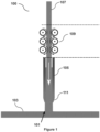
- the laser assisted spooling or unspooling system may be integrated with a 3D printing apparatus (or portion thereof) such as an extrusion printer nozzle feeding system of a 3D printing apparatus as depicted in Figure 1 .
- Figure 1 shows a schematic representation of an extrusion printer nozzle of a 3D printing apparatus (100) comprising a filament feeding system (109).
- Layers of 3D printed material (101) are laid down onto a heated base plate (103) using a heated nozzle (105).
- the feedstock printing material filament (107) is pulled (or drawn) by the filament feeder (109) and advanced towards the nozzle tip (111).
- the printing material (107) fed into such a system (100) is typically in the form of a long rod but for certain limited applications may be a spool (not shown).
- the present invention advantageously provides for systems and methods for unspooling such a spooled printing material.
- Filament-based 3D printing of glass or metal typically utilises rods or filaments of finite length, which are supplied to a heated extrusion nozzle using a feeding system, which may form part of a 3D printing apparatus / system, such as depicted in Figure 1 , or as described in WO 2018/163007 A1 .
- the molten material e.g. glass
- the molten material is subsequently deposited onto a build platform / plate that may itself be heated, such that a printed layer of material is formed along the printing direction.
- a typical filament feeding system for glass 3D printing applications is described for example in WO 2018/163007 A1 and with reference to Figure 2 .
- the filament feeding system (200) of WO 2018/163007 may be employed in a glass 3D printing apparatus / system (100) as described above and with reference to Figures 1 and 3 .
- the filament feeding system (200) comprises a filament loading or charging station (110) for sequentially loading individual filaments of material for printing into a printing nozzle or head (140).
- a detection station (120) is provided for detecting the presence / end of the printing material (glass filament), and is configured to provide a signal to a bonding station (130) for connecting the end of the leading filament of printing material to the beginning of the following filament of printing material.
- a feeding mechanism (150) in the form of opposing rotating wheels which contact opposite sides of the glass filament to provide a driving force on the filament is provided for feeding the printing material into the printing head (140).
- the glass filament (170) is melted in the printing head (140) such that molten printing material can be deposited on a moving build platform / plate (160).
- a filament feeding system such as that depicted in Figure 2 and described in WO 2018/163007 A1 overcomes some of the problems in the prior art of 3D printing of objects using discrete rods or filaments; there are nevertheless potential disadvantages. For example, typically, if one glass rod is consumed during printing of a 3D object (i.e. before the object is complete), a second rod must be loaded into the feeding system.
- the feeding system of WO 2018/163007 A1 which is configured to join adjacent feedstock filaments together, may lessen the potentially detrimental impact of changing feedstock during 3D printing of a single object; however, the abutting rods still form a surface-to-surface interface that is eventually pushed through the extrusion nozzle and melted before being incorporated into the 3D object.
- This surface-to-surface interface may trap impurities and/or air, such that, on printing, striae and/or bubbles could form inside the printed glass layer. Any such defects, even minor, can significantly lower the optical quality of the printed article and/or create points of weakness in the printed structure, and is a critical issue in the challenge of 3D-printing fully transparent, striae and bubble-free glass.
- One or more of these disadvantages are addressed by the laser spooling / unspooling system of this disclosure, as described herein.
- the feeding material / feedstock in the form of a spool rather than as a plurality of discrete rods.
- the problem of how to join the opposing ends of two adjacent feedstocks used in the same printing process may be avoided.
- it will generally be significantly easier to handle, transport and use a (glass) feedstock filament in the form of a relatively compact spool of material (such as a coil), rather than as a (long) linear rod of the same length.
- a considerable amount of additional material (feedstock) can be packaged into a single spool, which is relatively easy to transport, compared to the amount of the same material packaged in the form of a plurality of rods.
- Provision of spooled printing material may also avoid the need to provide potentially complex mitigating measures, such as the bonding (or fusion) station (130) and associated apparatus, such as depicted with respect to the system of Figure 2 .
- bonding (or fusion) station (130) and associated apparatus, such as depicted with respect to the system of Figure 2 .
- substantially linear rod or filament for feeding into a 3D printing system such as that described with reference to Figures 1 and 2 is not trivial.
- the present disclosure thus provides systems, apparatus and methods for spooling and unspooling of glass or metal filament feedstocks for various applications such as 3D printing.
- a heat source is needed.
- the heat source is targeted or focused to heat the filament at the desired starting point of curvature or straightening as the filament is coiled or uncoiled respectively.
- a laser or heating torch system may be used to provide a directional heat source for spooling or unspooling of a glass (or metal) filament.
- Laser heat sources are particularly useful since they may provide a highly directional and controllable source of heat.
- any suitable heating (e.g. laser) source may be used in accordance with various aspects and embodiments described herein, suitably, a CO 2 laser is chosen as a heating source since it provides a high level of process control over the intensity of laser light and, therefore, over heating temperature.
- a CO 2 laser system can be more economical to use, and may be a more ecological technology compared to e.g. classical torch systems.
- any other laser source such as a CO laser
- alternative heating system may be suitable or preferred in certain applications.
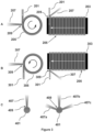
- FIG. 3A A schematic diagram of a filament spooling process according to the invention is shown in Figure 3A , illustrated from the side (left) as well as from the front (right).
- the apparatus is depicted in the context of a glass filament feedstock, but metal feedstocks may also be employed with similar or equivalent apparatus and process features, albeit taking account of any differences in the target heating temperature for the various different materials.
- a glass filament (201) is advanced towards and adjacent a rotating or spooling member, which in the depicted embodiment is in the form of a cylinder (203) for receiving the developing glass spool (205) in use.
- a rotating or spooling member which in the depicted embodiment is in the form of a cylinder (203) for receiving the developing glass spool (205) in use.
- Other configurations of the rotating member may alternatively be used, such as a wheel or similar apparatus.
- a laser source (not shown) provides a beam of laser light (207) directed towards a side of the glass filament (201) to heat at least a portion of the glass filament (201) to heat the surface of the filament to a temperature of approximately the glass transition temperature in the region designated as the desired bending point (209) of the filament (201), so that it can be properly received on the rotating cylinder (203).
- the heated temperature of the region of the glass filament is slightly above the glass transition temperature (e.g. at around the softening temperature) in order that the viscosity of the glass at the bending point (209) is low enough to enable sufficient bending or straightening for spooling or unspooling.
- the glass transition temperature will depend on the composition of the material to be spooled or unspooled, e.g. the target glass transition temperature may be between about 400°C and 900°C depending on the type of glass (and the softening temperature may be between about 500°C and 1,000°C).
- the rotating cylinder (203) is rotated about its longitudinal symmetry axis at a controlled, desired rotational speed (e.g. angular velocity) so that the speed of movement of a point on the circumference of the cylinder (or developing spool) matches the speed of linear advancement of the glass filament (201) towards the rotating cylinder (203) to achieve consistent laying down of glass filament on the developing spool (see Figure 2A, 2B).
- a controlled, desired rotational speed e.g. angular velocity
- a controller is required that communicates with a motor to control the speed of rotation of the rotating cylinder (203).
- the speed of rotation can be adjusted in a controlled manner to e.g. reduce the rate of rotation as the radius of the glass spool (205) increases with build-up of glass filament so that the speed of movement of a point on the circumference of the spool (205) is maintained at a substantially constant speed to match the linear advancement of the glass filament to be spooled.
- the controller may receive signals (or input) from sensors and/or vision systems configured to detect changes in the diameter (or radius) of the spooled material on the rotating cylinder (203) and may be configured to provide control signals to a motor or actuator of the rotating cylinder (203) in dependence on the received signals or input.
- an actuating member may be provided for moving the rotating cylinder (203) axially relative to the advancing glass filament (201) to control the axial location along the cylinder (203) at which the glass filament (201) is laid down.
- an even distribution of glass filament (201) may be achieved along the rotating cylinder (203), which can improve storage and transportation and may also provide benefits in the requirements for speed control of the rotating cylinder (203) during spooling or later unspooling operations during 3D glass printing.
- the speed of advancement of the glass filament (201) towards the rotating cylinder (203) may be controlled in order that the linear speed of advancement of the glass filament (201) substantially matches a speed of movement of a point on the outer circumference of the rotating cylinder (203) or glass spool (205) during a spooling process.
- the system may comprise a controller for controlling the speed of linear advancement of the filament prior to heating and subsequent spooling.
- sensors for measuring the linear speed of advancement of the filament prior to spooling, and/or the radial speed of the rotating cylinder or circumferential speed of movement of a point on the circumference of the growing spool may be provided.
- Such sensors may be arranged to provide signals or input into a controller for controlling the linear speed of advancement of the filament towards the rotating cylinder.
- a feedback system may, in some embodiments, also be employed to control the rotational movement of the spooling member and the linear movement of the filament so that the two speeds are substantially the same to ensure that the filament is not put under undesirable stress or strain during the spooling or unspooling process.
- any suitable speed or movement sensors may be used in accordance with such embodiments of the invention, and the 3D printing / spooling apparatus of the invention may comprise only one general, or more than one dedicated controller for controlling the various components of the system and apparatus.
- the system may further comprise adjusting the power or intensity of the beam of laser light (207) so that an even, desired heating and, hence, temperature of the glass filament (201) at the bending point (209) is achieved throughout the spooling process. Temperature measurements and subsequent power or intensity adjustment may assist achieving the desired temperature of the glass filament (201).
- the system may comprise controlling the lateral position of the advancing glass filament during the spooling process, such that the juxtaposition of the glass filament (201) and the rotating cylinder (203) or spool (205) is controlled.
- the longitudinal axis of the glass filament or rod (201) and, hence, the point of bending (209) of the glass filament (201) can be controlled relative to the axial location along the rotating cylinder (203) or spool (205), e.g.
- the point of bending (209) of the glass filament (201) can be controlled relative to the circumference of the cylinder (203) or spool (205), which may move radially outwards from the central longitudinal axis of the rotating member / cylinder (203) or spool (205) as glass filament builds up during a spooling process.
- corresponding adjustments in the position or angle of the laser beam (207) may be required to ensure that the desired bending point (209) is correctly heated to the desired temperature.
- any suitable sensors may be employed in order to detect the relative position of the glass filament (201) and/or rotating cylinder (203) or spool (205) and to provide signals to a controller (not shown) in order to control the relative position and speed of advancement of the glass filament, and/or to control the speed of rotation and relative axial location of the rotating member / cylinder (203).
- a controller not shown
- one or more sensors may be provided to detect / measure the temperature of the glass filament at the bending point (209) and to provide input into a controller or control system for adjusting or controlling the laser power or intensity provided to heat the glass filament (201).
- the heat source is particularly a laser, and typically a CO 2 laser; but any other lasers source known to the person skilled in the art may alternatively be used.
- the laser may have a central wavelength of at least about 9 ⁇ m and at most about 12 ⁇ m.
- the laser may have a central wavelength of 10 ⁇ m, 10.2 ⁇ m or 10.4 ⁇ m.
- the laser has a central wavelength of 10.6 ⁇ m.
- the laser may have a central wavelength of at least about 4 ⁇ m and at most about 7 ⁇ m.
- the laser may have a central wavelength of 5 ⁇ m, 5.2 ⁇ m or 5.4 ⁇ m.
- the laser has a central wavelength of 5.6 ⁇ m.
- the apparatus may include more than one laser source. Where more than one laser source is employed, each laser source may have the same or a different central wavelength. In some such embodiments, one laser source may be a CO 2 laser and one laser source may be a CO laser.
- the process / glass filament heating temperature may be determined by the composition of the glass used to form the glass filament.
- the target temperature for the glass rod at the bending point may be at least about 800°C and at most about 1,300°C as previously described.
- the process temperature may be approx. 1,000°C, such as approximately 1,040°C.
- any suitable glass may be used, for example, the glass may be a borosilicate, quartz or soda lime glass.
- the laser induced surface temperature of the glass filament should be limited to below the temperature at which glass ablation may occur.
- the temperature should be controlled to be below about 1,300°C (depending on the type / composition of glass) to avoid ablation.
- the diameter of the glass filament or rod can be any desired size that is suitable for 3D printing apparatuses and processes. For example, between about 0.5 and 18 mm, between about 1 mm and 15 mm, or between about 2 and 12 mm. In some embodiments, the diameter of the glass filament is at least about 1.5 mm or about 2 mm and at most about 6 mm or about 8 mm. In some embodiments, the diameter of the glass filament is at least about 2 mm and at most about 4 mm, which sizes are suitable for various 3D printing feeding mechanisms currently in use.
- the diameter of the laser beam and the diameter of the glass rod are suitably correlated.
- the laser power may be decreased if the laser diameter is decreased and vice versa in order to maintain the same desired light intensity and heating capacity. For example, this may ensure a constant maximum intensity and, hence, heating of glass to below an ablation temperature.
- the glass temperature at the bending point to just below the ablation temperature (e.g. between 50°C and 300°C below; or between 100°C and 200°C below ablation temperature; or alternatively to e.g. within about 25%, within about 20%, within about 15%, within about 10% or within about 5% below the ablation temperature) this may enable the maximum spooling speed to be achieved while avoiding damage to the glass filament.
- the spooling speed / linear speed of the glass filament is tightly controlled. If it is too low, the temperature on the surface of the glass may increase above the ablation temperature of the glass. On the other hand, if the speed of the glass filament is too high, given the timescale of thermal diffusion, the laser may not have sufficient time to heat and soften a sufficient proportion of the glass filament at the bending point to allow the filament to be bent and spooled.
- the speed of advancement of the glass filament may be adapted depending on the diameter of the spool (which affects the radial position of the bending point and effective spooling (or unspooling) point), to suitably maintain a constant spooling speed and, hence, avoid the need to frequently adjust the laser intensity.
- a velocity of between about 1 and 20 mm/s may be used, such as between about 2 and 15 mm/s or between about 3 and 12 mm/s.
- a linear glass filament velocity of between about 4 and 10 mm/s may be used in the filament feeding system of the disclosure.
- the speed may also be determined according to the diameter of the glass filament, and the above speeds may be particularly suitable for use with glass filaments having a diameter of between about 2 and 4 mm.
- more than one heat source may be used, to provide a more even heat distribution around the circumference of the glass filament and/or to provide more heat energy in a unit time so as to heat a larger volume of glass in the filament within a defined time period.
- two or three laser (or other heat) sources may be used, as depicted in Figure 3C .
- the lasers may be arranged at spaced radial positions relative to the glass filament: for example, at about 60°, at about 90° degrees and/or at about 180° from another laser source. It will be appreciated that any suitable laser source may be used.
- the at least two lasers may be of the same type, for example, CO 2 lasers as previously described.
- using multiple heat sources may allow for an increased spooling speed: for example, two identical heat or laser sources may allow the spooling speed to be doubled.
- a linear speed of movement of a glass filament and consequential spooling speed may be up to at least about 20 mm/s, up to at least about 30 mm/s and at most about 50 mm/s (depending on factors such as filament / rod diameter and composition).
- Glass rod unspooling may conveniently be achieved by essentially the reverse process to that used for the glass rod spooling process.
- a straight glass filament or rod is typically pulled by a feeding system of a 3D printing apparatus towards a printer head or nozzle.
- printing heads or nozzles comprise linear passages for movement of the glass filament therethrough. Accordingly, during a 3D printing process, it is typically necessary to provide a (substantially) straight glass filament or rod, in order that it can be received into and pass through the printer head or nozzle without breaking, which would undesirably and inadvertently create a discontinuous supply of glass printing material, which the use of a spool of material seeks to avoid.
- heat - typically in the form of energy from laser light - is provided to a designated bending point of the glass filament adjacent a spool of glass filament to be unwound.
- the unspooling glass filament is heated to a desired glass transition / softening temperature to allow straightening of the glass filament as it is pulled towards the 3D printer head prior to its passage into the nozzle / printer head (see Figure 3B ).
- the temperature of heating of the glass filament and the mechanism for heating of the glass filament for unspooling may be the same as that for spooling, as described above and those details are not repeated here, except, of course, that rotation of the rotating member and linear movement of the developing straightened filament are in the opposite direction.
- a spooled glass filament (301) is pulled towards a rotating cylinder, wheel or spool (303) on which the glass spool (305) rests prior to straightening.
- a laser source (not shown) provides a beam of laser light (307) directed towards a side of the spooled glass filament (301) to heat at least a portion of the glass filament (301) to a temperature of approximately the glass transition temperature or softening point in the region designated as the desired straightening point (309) of the filament (301) to be properly received by any filament feeding system for example a 3D printing filament feeding system.
- the heated temperature of the surface region of the glass filament is slightly above the glass transition temperature (e.g. between about 500°C and 700°C), e.g. around the softening temperature, in order that the viscosity of the glass at the straightening point (309) is low enough for the straightening / unspooling process.
- the rotating cylinder (303) when in use in a 3D printing apparatus, is rotated about its symmetry axis at a controlled, desired rotational speed so that the speed of movement of a point on the circumference of the cylinder (or developing spool) matches the speed of linear advancement of the glass filament (301) towards a filament feeder of e.g. a 3D printing system (not shown) to achieve consistent straightening of the spooled glass filament to be pulled by the filament feeder (see Figure 2B).
- a filament feeder e.g. a 3D printing system (not shown)
- the speed of angular rotation of the rotating cylinder (303) is adjusted in a controlled manner to e.g. increase the rate of angular rotation as the radius of the glass spool (205) decreases with straightening glass filament so that the (effective linear) speed of movement of a point on the circumference of the spool (305) is maintained at a substantially constant speed throughout the unspooling process.
- the rotating cylinder (303) may be moved axially relative to the pulled glass filament (301) to control the axial location along the cylinder (303) at which the glass filament (301) is unspooled. In this way, the glass filament (301) may be unspooled evenly and smoothly along the length of the rotating cylinder (303).
- the speed of pulling of the glass filament (301) from the rotating cylinder (303) may be controlled in order that the linear speed of pulling of the glass filament (301), by e.g. a filament feeder, substantially matches a speed of movement of a point on the outer circumference of the rotating cylinder (303) or glass spool (205) during a unspooling process.
- the system may further comprise adjusting the power or intensity of the beam of laser light (307) so that an even, desired heating and, hence, temperature of the glass filament (301) at the straightening point (209) is achieved throughout the unspooling process.
- the rate of printing can be controlled to a desired, constant speed of deposition.
- the unspooling speed of the filament or rod is accurately matched to the material deposition speed of 3D printing, e.g. to avoid distortion of the filament for stretching (or breaking) or compaction.
- the feeding mechanism may control (directly or indirectly) the rate of rotation of the spool, in order to ensure that the feed material (e.g. filament) movement is essentially identical.
- the rotating cylinder may be mechanically or controllably coupled to the 3D printing feeder mechanism so that it is caused to rotate in consequence of the feed material being pulled or pushed through the feeder mechanism of the 3D printing (or other) apparatus.
- the rotating cylinder may have a low-friction rotation arrangement allowing for passive rotation as the filament it pulled by the feeder mechanism.
- the system may comprise controlling the longitudinal and/or lateral position of the spooled glass filament (301). Accordingly, the point of straightening (309), may be controlled relative to the 3D printing apparatus, so that the point of straightening (309) of the glass filament (301) can be adjusted to take account of the relative position of the circumference of the cylinder (303) or spool (305), which may move inwards towards the central longitudinal axis of the cylinder (303) or spool (305) as glass filament is removed during an unspooling process.
- the position or orientation of the laser or other heat source need not be adjusted as the position at which unspooling commences beneficially remains constant and in line with the 3D printing apparatus.
- the apparatus comprises a mechanism for adjustment the target position or angle of the heat source or laser beam (307) to ensure that the desired straightening point (309) is correctly heated to the desired temperature despite potential (minor) movements in the position at which the filament is heated and unwound from the rotating spool.
- apparatus may be provided for translational and/or rotational adjustments in the position or orientation of the heat source.
- mechanisms may also or alternatively be provided for adjusting the angle / orientation or position of the heat / laser guiding / focusing devices, such as mirrors and/or lenses.
- any suitable sensors or other vision devices may be employed in order to detect the relative position of the glass filament (301) and/or rotating cylinder (303) or spool (305) and to provide signals to a controller (not shown) in order to control the relative position and speed of pulling of the glass filament and/or to control the speed of rotation and relative axial or lateral location of the rotating cylinder (303).
- a controller not shown
- one or more sensors may be provided to detect / measure the temperature of the glass filament at the heating / straightening point (209) and to provide input into a controller or control system for adjusting or controlling the laser power or intensity provided to heat the glass filament (301).
- the rotational speed of the spool and/or the relative position of the spool with respect to the laser/ laser source and 3D printing apparatus, so that the desired bending point of the spooled glass filament is maintained at the correct position for heating by the source of heat.
- the axial position (and optionally the lateral position) of the glass spool may be adjusted during the unspooling process so that the bending point of the glass filament and particularly the point at which the heat or laser source contacts the glass filament remains constant.
- the unspooled filament may be maintained at a sufficiently high temperature after unspooling to allow for some flexibility in the filament (e.g. by maintaining a temperature that allows some bending), which may allow for realignment of the unspooled filament with a feeding mechanism or other component of a 3D printing apparatus. In this way it may not be necessary to regularly correct for the position of the bending point of the unspooling material relative to the relevant component of the 3D printing apparatus (e.g. the feeder mechanism).
- the mechanism for maintaining a sufficient temperature of the filament may be any convenient device, such as a laser source, a heated chamber, heated rollers or any other suitable heating elements as may be provided.
- the speed of rotation of the glass spool may be adjusted and controlled to ensure a constant rate of unspooling (as discussed in relation to spooling) so that the glass filament is heated to the desired temperature at the time of bending.
- the speed of unspooling should suitably be matched to the printing speed, to ensure a consistent speed of unspooling for printing. This is particularly important where a continuous unspooling and printing process is desired. It will therefore be appreciated that a slower (or faster) rate of unspooling may be achieved in comparison to a spooling operation.
- a constant glass rod 'reservoir' for printing may be provided, which eliminates the need to abut discrete glass (or metal) rods and the consequential surface-surface interfaces, which importantly - in accordance with aspects and embodiments of this disclosure - reduces the risk of striae or bubbles forming in the printing object.
- Figure 3C shows a schematic representation of a cross section of a glass filament at the bending point (409) of a spooling and unspooling process.
- the left image illustrates an apparatus and process using a single laser (407) to heat the glass filament (401)
- the right image illustrates an arrangement and method utilising three lasers (407a, 407b, 407c) to heat the glass filament (401).
- the glass filament or spool may be preheated before it is heated by the laser or other heat source.
- a speed increase in spooling or unspooling can be achieved by preheating the glass filament.
- the filament may be more quickly heated to the desired softening / glass transition temperature without risking ablation of the glass material.
- the speed of spooling (or unspooling) may be increased by at least 10 or 20%, such as up to about 100%, up to about 75%, up to about 50% or up to about 25%, according to the desired process speed, or as may be convenient.
- Preheating of the glass filament may have other beneficial effects also, for example, condensed water and other vapors on the rod or spool surface may be evaporated before being exposed to the high temperature zone of the heat source / laser beam at the bending point.
- Preheating of the filament may be achieved by any suitable means, for example, in an oven, by radiant heat, or using any other laser or heat source, for example, in some embodiments, a low power or diffuse heat source may be directed towards the glass spool so that the glass spool is maintained at above ambient / room temperate before it reaches the point at which heat treatment for unspooling or spooling is provided.
- the rotating member may alternatively provide heat to the spool.
- the penetration depth through glass of light energy from a laser may determine the speed and effectiveness with which a glass filament can be melted and bent without causing ablation.
- the energy is typically absorbed by the glass within a small volume at the surface of the glass due to the very small penetration depth of only a few microns for a CO 2 laser with 10.6 ⁇ m central wavelength. Consequently, the surface of the glass filament is heated rapidly, but volumetric heating of the glass rod relies on subsequent thermal diffusion. This is the rate limiting step for volumetric heating of a glass filament using a CO 2 laser as a heat source, and another reason why spooling and unspooling speed may be strongly dependent on the thickness / diameter of the glass filament.
- the use of more than two or three (CO 2 ) lasers and/or increasing the laser power and intensity of light energy may be detrimental to the integrity of the glass by rapidly causing saturation of absorbed energy at the surface of the glass, with consequential overheating and local ablation of glass.
- CO 2 the laser power and intensity of light energy
- the maximum spooling and unspooling speed range is suitably of the order of 20 mm/s to 50 mm/s, which would achieve a spooling time of 0.5 hours to 1.5 hours for a 100 m long glass filament.
- This speed is approximately a factor of two to five times faster than the speed currently and typically used extrusion of glass rods / filaments during 3D glass printing, and so the rate of unspooling of a glass filament according to this disclosure should not limit the speed of glass 3D printing using glass spools provided in accordance with the present disclosure.
- a CO 2 laser with a main de-excitation transition at 10.6 ⁇ m wavelength and a second transition at 9.6 ⁇ m, a linewidth in the order of a few hundred MHz (unstabilised), and a laser intensity of about 2 W/mm 2 was used to test the parameters for spooling and unspooling of a glass filament comprising soda-lime glass .
- Soda-lime glass has a process temperature of approx. 1,040°C, although glasses with a lower or higher process temperature may be used.
- the achieved speed range of unspooling of between 8 and 10 mm/s is beneficial, since is matches the glass filament extrusion speeds for a typical glass 3D printing process, e.g. using the system described with reference to Figures 1 and 3 above.
Landscapes
- Engineering & Computer Science (AREA)
- Chemical & Material Sciences (AREA)
- Materials Engineering (AREA)
- Mechanical Engineering (AREA)
- Manufacturing & Machinery (AREA)
- Physics & Mathematics (AREA)
- Organic Chemistry (AREA)
- Metallurgy (AREA)
- Crystallography & Structural Chemistry (AREA)
- Thermal Sciences (AREA)
- Life Sciences & Earth Sciences (AREA)
- General Life Sciences & Earth Sciences (AREA)
- Chemical Kinetics & Catalysis (AREA)
- General Chemical & Material Sciences (AREA)
- Geochemistry & Mineralogy (AREA)
- Electromagnetism (AREA)
- Optics & Photonics (AREA)
- Automation & Control Theory (AREA)
- Analytical Chemistry (AREA)
- Laser Beam Processing (AREA)
Priority Applications (2)
| Application Number | Priority Date | Filing Date | Title |
|---|---|---|---|
| EP21217624.2A EP4201552A1 (fr) | 2021-12-23 | 2021-12-23 | Appareils, systèmes et procédés de bobinage et de débobinage |
| PCT/EP2022/087792 WO2023118594A1 (fr) | 2021-12-23 | 2022-12-23 | Appareil, systèmes et procédés d'enroulement et de déroulement |
Applications Claiming Priority (1)
| Application Number | Priority Date | Filing Date | Title |
|---|---|---|---|
| EP21217624.2A EP4201552A1 (fr) | 2021-12-23 | 2021-12-23 | Appareils, systèmes et procédés de bobinage et de débobinage |
Publications (1)
| Publication Number | Publication Date |
|---|---|
| EP4201552A1 true EP4201552A1 (fr) | 2023-06-28 |
Family
ID=79164772
Family Applications (1)
| Application Number | Title | Priority Date | Filing Date |
|---|---|---|---|
| EP21217624.2A Withdrawn EP4201552A1 (fr) | 2021-12-23 | 2021-12-23 | Appareils, systèmes et procédés de bobinage et de débobinage |
Country Status (2)
| Country | Link |
|---|---|
| EP (1) | EP4201552A1 (fr) |
| WO (1) | WO2023118594A1 (fr) |
Cited By (1)
| Publication number | Priority date | Publication date | Assignee | Title |
|---|---|---|---|---|
| DE102024117841A1 (de) | 2024-06-25 | 2026-01-08 | Schott Ag | Glasfilament für den 3D-Druck und dessen Verwendung |
Citations (8)
| Publication number | Priority date | Publication date | Assignee | Title |
|---|---|---|---|---|
| US5151966A (en) * | 1990-06-26 | 1992-09-29 | Alcatel Fibres Optiques | Optical fiber suitable for use in optical time domain reflectometry and method of manufacturing it |
| US6539154B1 (en) * | 2000-10-18 | 2003-03-25 | Corning Incorporated | Non-constant dispersion managed fiber |
| US20180221950A1 (en) * | 2016-12-02 | 2018-08-09 | Markforged, Inc. | Sintering additively manufactured parts in a fluidized bed |
| WO2018163007A1 (fr) | 2017-03-05 | 2018-09-13 | Micron 3Dp Ltd. | Alimentation continue en filament pour fabrication additive |
| WO2018163006A1 (fr) | 2017-03-05 | 2018-09-13 | Micron 3Dp Ltd. | Système d'impression 3d pour l'impression de matériaux à température de fusion élevée |
| US20190001396A1 (en) * | 2009-05-04 | 2019-01-03 | Orametrix, Inc. | Apparatus and Method for Customized Shaping of Orthodontic Archwires and Other Medical Devices |
| US10189204B2 (en) * | 2016-12-14 | 2019-01-29 | Desktop Metal, Inc. | Composite feedstock for additive manufacturing |
| US20210123120A1 (en) * | 2019-10-23 | 2021-04-29 | Ii-Vi Delaware, Inc. | Aluminum-Scandium Wire for Additive Processing Operation |
Family Cites Families (3)
| Publication number | Priority date | Publication date | Assignee | Title |
|---|---|---|---|---|
| CN203876241U (zh) * | 2014-06-17 | 2014-10-15 | 韩成超 | 一种恒温桌面3d打印机 |
| WO2018204749A2 (fr) * | 2017-05-05 | 2018-11-08 | 3Dp Unlimited, Llc D/B/A 3D Platform | Dispositif de redressement de matériau pour alimenter en matériau une machine de fabrication additive |
| FR3114536B1 (fr) * | 2020-09-25 | 2023-02-10 | Ecole Nat Superieure Darts Et Metiers Ensam | Procédé d’enroulage d’un filament pour dispositif de fabrication additive |
-
2021
- 2021-12-23 EP EP21217624.2A patent/EP4201552A1/fr not_active Withdrawn
-
2022
- 2022-12-23 WO PCT/EP2022/087792 patent/WO2023118594A1/fr not_active Ceased
Patent Citations (8)
| Publication number | Priority date | Publication date | Assignee | Title |
|---|---|---|---|---|
| US5151966A (en) * | 1990-06-26 | 1992-09-29 | Alcatel Fibres Optiques | Optical fiber suitable for use in optical time domain reflectometry and method of manufacturing it |
| US6539154B1 (en) * | 2000-10-18 | 2003-03-25 | Corning Incorporated | Non-constant dispersion managed fiber |
| US20190001396A1 (en) * | 2009-05-04 | 2019-01-03 | Orametrix, Inc. | Apparatus and Method for Customized Shaping of Orthodontic Archwires and Other Medical Devices |
| US20180221950A1 (en) * | 2016-12-02 | 2018-08-09 | Markforged, Inc. | Sintering additively manufactured parts in a fluidized bed |
| US10189204B2 (en) * | 2016-12-14 | 2019-01-29 | Desktop Metal, Inc. | Composite feedstock for additive manufacturing |
| WO2018163007A1 (fr) | 2017-03-05 | 2018-09-13 | Micron 3Dp Ltd. | Alimentation continue en filament pour fabrication additive |
| WO2018163006A1 (fr) | 2017-03-05 | 2018-09-13 | Micron 3Dp Ltd. | Système d'impression 3d pour l'impression de matériaux à température de fusion élevée |
| US20210123120A1 (en) * | 2019-10-23 | 2021-04-29 | Ii-Vi Delaware, Inc. | Aluminum-Scandium Wire for Additive Processing Operation |
Cited By (1)
| Publication number | Priority date | Publication date | Assignee | Title |
|---|---|---|---|---|
| DE102024117841A1 (de) | 2024-06-25 | 2026-01-08 | Schott Ag | Glasfilament für den 3D-Druck und dessen Verwendung |
Also Published As
| Publication number | Publication date |
|---|---|
| WO2023118594A1 (fr) | 2023-06-29 |
Similar Documents
| Publication | Publication Date | Title |
|---|---|---|
| US10427332B2 (en) | Fiber placement and production method | |
| JP5235987B2 (ja) | 移動中の帯状ガラスに切断線を設ける装置、システム及び方法 | |
| US20170158543A1 (en) | Method and Apparatus For Additive Manufacturing of Objects Using Droplets of Molten Glass | |
| CN107108317B (zh) | 用于对玻璃制品的边缘进行密封的方法和设备 | |
| EP0999189B1 (fr) | Procédé et dispositif d'étirage d'une préforme et d'étirage d'une fibre optique à partir de la préforme étirée | |
| SE521124C2 (sv) | Anordning samt metod för framställande av en tredimensionell produkt | |
| JP7098053B2 (ja) | 加工機械 | |
| TW201805100A (zh) | 雷射處理設備以及方法 | |
| EP1426343A2 (fr) | Procédé et appareil pour l'étirage d'une fibre optique à partir d'une préforme | |
| SE524439C2 (sv) | Anordning samt metod för framställande av en tredimensionell produkt | |
| CN111315558A (zh) | 用于操作增材制造喷嘴的装置、系统和方法 | |
| EP4201552A1 (fr) | Appareils, systèmes et procédés de bobinage et de débobinage | |
| JP2018197185A (ja) | 帯材の厚みを制御する方法および装置 | |
| JP7642847B2 (ja) | 熱硬化性トウプレグ半製品からコンポーネントを生産するための配置装置及び方法 | |
| KR20140122252A (ko) | 공작물의 표면을 레이저 가공하는 또는 공작물의 외부면 또는 내부면 상의 코팅을 후처리하는 장치 | |
| US20130209077A1 (en) | Target supply apparatus and target supply method | |
| JP5822285B2 (ja) | 熱間三次元曲げ加工装置 | |
| KR20240035440A (ko) | 유리 물체의 적층 제조 방법 및 장치 | |
| US11772144B2 (en) | Process for the production of thin-walled hollow profiles which are composed of nonferrous metals and have small diameters | |
| JP2010045290A (ja) | 空芯コイル巻線装置およびその制御方法 | |
| US20240368018A1 (en) | Method and apparatus for additive manufacturing of glass | |
| CN108585469A (zh) | 光纤的制备方法 | |
| JP3812357B2 (ja) | 光ファイバ母材の延伸方法及び延伸装置 | |
| CN104968467A (zh) | 使管道端部具有激光热焊丝层的方法和系统 | |
| WO2005056487A1 (fr) | Procede d'etirage d'une preforme de fibre optique, et dispositif d'etirage |
Legal Events
| Date | Code | Title | Description |
|---|---|---|---|
| PUAI | Public reference made under article 153(3) epc to a published international application that has entered the european phase |
Free format text: ORIGINAL CODE: 0009012 |
|
| STAA | Information on the status of an ep patent application or granted ep patent |
Free format text: STATUS: THE APPLICATION HAS BEEN PUBLISHED |
|
| AK | Designated contracting states |
Kind code of ref document: A1 Designated state(s): AL AT BE BG CH CY CZ DE DK EE ES FI FR GB GR HR HU IE IS IT LI LT LU LV MC MK MT NL NO PL PT RO RS SE SI SK SM TR |
|
| STAA | Information on the status of an ep patent application or granted ep patent |
Free format text: STATUS: THE APPLICATION IS DEEMED TO BE WITHDRAWN |
|
| 18D | Application deemed to be withdrawn |
Effective date: 20240103 |