EP4201566A1 - Machine à scier à spin - Google Patents
Machine à scier à spin Download PDFInfo
- Publication number
- EP4201566A1 EP4201566A1 EP22215337.1A EP22215337A EP4201566A1 EP 4201566 A1 EP4201566 A1 EP 4201566A1 EP 22215337 A EP22215337 A EP 22215337A EP 4201566 A1 EP4201566 A1 EP 4201566A1
- Authority
- EP
- European Patent Office
- Prior art keywords
- arm
- cable
- cutting
- pulleys
- section
- Prior art date
- Legal status (The legal status is an assumption and is not a legal conclusion. Google has not performed a legal analysis and makes no representation as to the accuracy of the status listed.)
- Granted
Links
Images

Classifications
-
- B—PERFORMING OPERATIONS; TRANSPORTING
- B23—MACHINE TOOLS; METAL-WORKING NOT OTHERWISE PROVIDED FOR
- B23D—PLANING; SLOTTING; SHEARING; BROACHING; SAWING; FILING; SCRAPING; LIKE OPERATIONS FOR WORKING METAL BY REMOVING MATERIAL, NOT OTHERWISE PROVIDED FOR
- B23D57/00—Sawing machines or sawing devices not covered by one of the preceding groups B23D45/00 - B23D55/00
- B23D57/0007—Sawing machines or sawing devices not covered by one of the preceding groups B23D45/00 - B23D55/00 using saw wires
-
- B—PERFORMING OPERATIONS; TRANSPORTING
- B23—MACHINE TOOLS; METAL-WORKING NOT OTHERWISE PROVIDED FOR
- B23D—PLANING; SLOTTING; SHEARING; BROACHING; SAWING; FILING; SCRAPING; LIKE OPERATIONS FOR WORKING METAL BY REMOVING MATERIAL, NOT OTHERWISE PROVIDED FOR
- B23D57/00—Sawing machines or sawing devices not covered by one of the preceding groups B23D45/00 - B23D55/00
- B23D57/003—Sawing machines or sawing devices working with saw wires, characterised only by constructional features of particular parts
- B23D57/0069—Sawing machines or sawing devices working with saw wires, characterised only by constructional features of particular parts of devices for tensioning saw wires
-
- B—PERFORMING OPERATIONS; TRANSPORTING
- B23—MACHINE TOOLS; METAL-WORKING NOT OTHERWISE PROVIDED FOR
- B23D—PLANING; SLOTTING; SHEARING; BROACHING; SAWING; FILING; SCRAPING; LIKE OPERATIONS FOR WORKING METAL BY REMOVING MATERIAL, NOT OTHERWISE PROVIDED FOR
- B23D57/00—Sawing machines or sawing devices not covered by one of the preceding groups B23D45/00 - B23D55/00
- B23D57/0084—Sawing machines or sawing devices not covered by one of the preceding groups B23D45/00 - B23D55/00 specially adapted for sawing under water or at places accessible with difficulty
-
- B—PERFORMING OPERATIONS; TRANSPORTING
- B23—MACHINE TOOLS; METAL-WORKING NOT OTHERWISE PROVIDED FOR
- B23D—PLANING; SLOTTING; SHEARING; BROACHING; SAWING; FILING; SCRAPING; LIKE OPERATIONS FOR WORKING METAL BY REMOVING MATERIAL, NOT OTHERWISE PROVIDED FOR
- B23D57/00—Sawing machines or sawing devices not covered by one of the preceding groups B23D45/00 - B23D55/00
- B23D57/003—Sawing machines or sawing devices working with saw wires, characterised only by constructional features of particular parts
- B23D57/0038—Sawing machines or sawing devices working with saw wires, characterised only by constructional features of particular parts of frames; of tables
-
- B—PERFORMING OPERATIONS; TRANSPORTING
- B23—MACHINE TOOLS; METAL-WORKING NOT OTHERWISE PROVIDED FOR
- B23D—PLANING; SLOTTING; SHEARING; BROACHING; SAWING; FILING; SCRAPING; LIKE OPERATIONS FOR WORKING METAL BY REMOVING MATERIAL, NOT OTHERWISE PROVIDED FOR
- B23D57/00—Sawing machines or sawing devices not covered by one of the preceding groups B23D45/00 - B23D55/00
- B23D57/003—Sawing machines or sawing devices working with saw wires, characterised only by constructional features of particular parts
- B23D57/0053—Sawing machines or sawing devices working with saw wires, characterised only by constructional features of particular parts of drives for saw wires; of wheel mountings; of wheels
-
- B—PERFORMING OPERATIONS; TRANSPORTING
- B23—MACHINE TOOLS; METAL-WORKING NOT OTHERWISE PROVIDED FOR
- B23D—PLANING; SLOTTING; SHEARING; BROACHING; SAWING; FILING; SCRAPING; LIKE OPERATIONS FOR WORKING METAL BY REMOVING MATERIAL, NOT OTHERWISE PROVIDED FOR
- B23D57/00—Sawing machines or sawing devices not covered by one of the preceding groups B23D45/00 - B23D55/00
- B23D57/003—Sawing machines or sawing devices working with saw wires, characterised only by constructional features of particular parts
- B23D57/0061—Sawing machines or sawing devices working with saw wires, characterised only by constructional features of particular parts of devices for guiding or feeding saw wires
Definitions
- the present invention relates to a device for sawing large sized built up structures.
- the present invention relates to a device for sawing large sized structures using a filament sawing element.
- EP3153265 discloses a system for guiding a cutting device around the wall of a high upright object having a cylindrical shape.
- the system herein comprises a ring which can be placed around the object to be sawn, wherein clamping elements fasten the ring to the casing of the object.
- WO2000078491 discloses a pipe cutting device.
- the device is suitable for use under water for cutting pipelines.
- the device comprises a telescopic frame which can be placed over the wall of the pipe.
- the device further comprises a sawing device pivotally coupled to one side of the telescopic frame.
- WO2011018396 discloses a system for cutting structural elements such as pipes, support pillars, etc.
- the system comprises a cutting wire guided around a plurality of pulleys provided on a frame, which is placed around the object to be sawn.
- the frame further comprises two legs provided parallel to each other, wherein the object to be sawn can be placed between the legs. Several pulleys can move along the two legs, pushing the cutting wire through the object to be sawn.
- the cutting wire drive is mounted in the frame around the object to be sawn.
- the main limitation common to all these systems is that they require too much space around the structure/object to be cut, therefore rendering such systems inadequate for use in confined spaces.
- WO2019151874 discloses a system for cutting a wall.
- the system herein comprises a main saw device placed on an inner part of the wall, which can move around the wall by means of rails.
- the system further comprises an additional sawing device which can move around the outer part of the wall by means of rails attached to the outer part of the wall.
- the wall is sawn by means of a cutting wire which is driven by the main sawing device through a pre-drilled opening to the auxiliary sawing device.
- the main disadvantage of this system is the need to access the inside of the object/structure to be cut in order to pass a cutting cable.
- the aim of the invention is to provide a method which eliminates those disadvantages.
- the invention thereto aims to provide a device for the cutting of structures, which device can be used in confined spaces and from the outside of the object/structure to be cut.
- the present invention and embodiments thereof serve to provide a solution to one or more of above-mentioned disadvantages.
- the present invention relates to overhead sawing device according to claim 1. Preferred embodiments of the device are shown in any of the claims 2 to 9.
- the present invention relates to a method according to claim 10. More particular, the method herein relates to the use of the device for the cutting of objects/structures. Preferred embodiments of the method are shown in any of the claims 11 and 12.
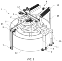
- the present invention concerns an overhead sawing device.
- a compartment refers to one or more than one compartment.
- the terms "one or more” or “at least one”, such as one or more or at least one member(s) of a group of members, is clear per se , by means of further exemplification, the term encompasses inter alia a reference to any one of said members, or to any two or more of said members, such as, e . g ., any ⁇ 3, ⁇ 4, ⁇ 5, ⁇ 6 or ⁇ 7 etc. of said members, and up to all said members.
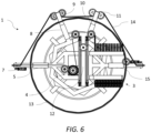
- the invention provides an overhead sawing device comprising:
- Each of the at least two rotatable arms further comprises a second vertical section extending downwards from the first radially extending section, the distal end of said second section being further equipped with at least two horizontal pulleys.
- all but the pulley of the drive unit are free running. In this way resistance and control complexity are advantageously reduced.
- the second pulleys of the first arm and the second arm are pivotable. This advantageously permits passing/receiving the cutting cable to/from the horizontal pulleys of each rotatable arm with minimal resistance and risk of dislodging the cutting cable.
- first arm and second arm are horizontally adjustable in length.
- first and second arms are advantageously able to clear the perimeter of the structure to be cut. This allows for the first and second arms to pass/receive cutting cable to/from the horizontal pulleys of the rotatable arms without said cable touching the structure to be cut other than between the pullers of the two rotatable arms. In this way, excessive friction is advantageously avoided, allowing for a better and more efficient cutting action between the pulleys of the rotatable arms.
- all rotatable legs are horizontally adjustable in length. This allows the rotatable arms to clear the perimeter of the structure to be cut, which permits an unhindered movement of the rotatable arms during the cutting operation.
- the range of horizontal adjustment of the first and second arms is larger than that of the horizontal range of adjustment of the rotatable arms. In this way, the first and second arms can be adjusted so as to distance themselves from the perimeter of the structure to be cut such that a sufficient gap is advantageously created for the movement of the rotatable arms during the cutting operation.
- all rotatable legs are adjustable in height.
- all arms are adjustable in height.
- the device can cut sections of varying sizes from a structure to be cut. This is particularly advantageous in situations where the structure to be cut comprises different perimeters at different heights.
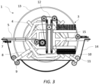
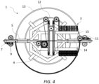
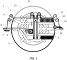
- the distance between the first row of pulleys and the second row of pulleys of the cable storage is adjustable.
- one of the rows of pulley is mounted displaceably along one direction in relation to the first package. More preferably, both rows of pulleys are mounted displaceably along one direction in relation to one another. In this way, the length of the cutting cable provided to all other elements of the device is varied by displacing one or both rows of pulleys of the cable storage relative to each other.
- the axis of the first row of pulleys in the cable storage define an angle with the axis of the second row of pulleys of the cable storage. This permits a better transfer of the cutting cable between the pulleys in the first row to the pulleys in the second row and back. In this way, the risk of the cutting cable jumping out of a groove of a pulley of the cable storage is greatly reduced. Furthermore, the angle define by the axes of the two rows of pulleys advantageously reduces the tensions that would otherwise result in an uneven bearing of the pulleys on their respective axis.
- the telescopic cable tensioning element comprises a first longitudinal element slidably connected to a second longitudinal element, which first longitudinal element comprises a first and a third horizontal pulleys, which pulleys are longitudinally displaceable relative to a second horizontal pulley on the second longitudinal element.
- This cable tensioning element permits regulating the tension on the cable before and during cutting. This advantageously permits regulating the slack in the cable, thereby preventing said cable from experiencing excessive force spikes which could otherwise result in the weakening or even breakage of the cable.
- Proper cable tensioning has also the advantage of preventing undesired wear patterns on the cutting elements of the cable.
- first and the second longitudinal elements of the telescopic cable tensioning element are movable relative to each other by means of at least one actuator.
- the at least one actuator is in communication with a controller. In this way, tension on the cable can be monitored and automatically adjusted for better cut performance, safety and reduced stress on the device.
- Another aspect of the invention relates to a method of cutting a structure using the device of any claim 1 to claim 9 comprising the steps of:
- the device can be placed and operated wile requiring a minimal amount of space around the object/structure to be cut. This advantageously permits operating the device even is very confined spaces.
- starting the cutting includes the steps of:
- the cut is initiated at the outer perimeter of the object/structure.
- This advantageously avoids the need to first insert the cable into predrilled holes in the object/structure or the need to access the inside of the object/structure in order to pass the cable.
- the kerf created by the cable does not immediately reach an orientation where the cable is under minimal tension.
- the kerf created by the cable is already aligned with the path of the cable. In this way, no undue tension is imposed upon the cutting cable.
- kerf is to be understood as the slit created by a saw.
- kerf is to be understood as the slit cut on the object/structure by the cutting cable.
- finishing the cutting includes the steps of:
- the device can perform a cut from start to finish without repositioning of the device. This advantageously avoids any need to align multiple cuts, the extra work and time such operation would entail, as well as, time lost to the repositioning of the machine.
Landscapes
- Engineering & Computer Science (AREA)
- Mechanical Engineering (AREA)
- Sawing (AREA)
- Processing Of Stones Or Stones Resemblance Materials (AREA)
Applications Claiming Priority (1)
| Application Number | Priority Date | Filing Date | Title |
|---|---|---|---|
| BE20216058A BE1030093B1 (nl) | 2021-12-24 | 2021-12-24 | Spinzaaginrichting |
Publications (3)
| Publication Number | Publication Date |
|---|---|
| EP4201566A1 true EP4201566A1 (fr) | 2023-06-28 |
| EP4201566C0 EP4201566C0 (fr) | 2025-11-05 |
| EP4201566B1 EP4201566B1 (fr) | 2025-11-05 |
Family
ID=80787332
Family Applications (1)
| Application Number | Title | Priority Date | Filing Date |
|---|---|---|---|
| EP22215337.1A Active EP4201566B1 (fr) | 2021-12-24 | 2022-12-21 | Machine à scier à spin |
Country Status (5)
| Country | Link |
|---|---|
| US (1) | US12564891B2 (fr) |
| EP (1) | EP4201566B1 (fr) |
| JP (1) | JP7525585B2 (fr) |
| BE (1) | BE1030093B1 (fr) |
| CA (1) | CA3185494C (fr) |
Cited By (1)
| Publication number | Priority date | Publication date | Assignee | Title |
|---|---|---|---|---|
| CN117773229A (zh) * | 2024-02-23 | 2024-03-29 | 上海宏信设备工程有限公司 | 一种建筑工程用大型绳锯机 |
Families Citing this family (1)
| Publication number | Priority date | Publication date | Assignee | Title |
|---|---|---|---|---|
| CN121358846A (zh) | 2023-06-09 | 2026-01-16 | 新博基股份有限公司 | 菌株的物质生产 |
Citations (5)
| Publication number | Priority date | Publication date | Assignee | Title |
|---|---|---|---|---|
| WO2000078491A1 (fr) | 1999-06-22 | 2000-12-28 | Oceaneering International, Inc. | Installation de decoupe pour conduites |
| WO2011018396A1 (fr) | 2009-08-13 | 2011-02-17 | Ts R&D S.R.L. | Machine de coupe pour éléments de construction tels que jambages, poutres, poutrelles en i et analogues utilisés pour supporter des structures en acier, en béton, en acier et en béton, en matériaux de type pierre ou analogue |
| EP3153265A1 (fr) | 2015-10-05 | 2017-04-12 | Mirko Bergmann | Système de guidage d'outil et procédé de découpe horizontale |
| WO2019151874A1 (fr) | 2018-01-30 | 2019-08-08 | 1Diamond As | Scie à fil de coupe à structure de paroi |
| CN113414879A (zh) * | 2021-08-05 | 2021-09-21 | 浙江协力机械工具有限公司 | 一种陶瓷切割专用设备 |
Family Cites Families (11)
| Publication number | Priority date | Publication date | Assignee | Title |
|---|---|---|---|---|
| JP2004114562A (ja) | 2002-09-27 | 2004-04-15 | Dymosha Co Ltd | ワイヤソー式切断装置及びこの装置を用いた切断工法 |
| US7922424B2 (en) * | 2008-06-20 | 2011-04-12 | Tetra Technologies, Inc. | Method of cutting target members using a cutting saw device |
| US8833219B2 (en) * | 2009-01-26 | 2014-09-16 | Illinois Tool Works Inc. | Wire saw |
| KR100931878B1 (ko) | 2009-05-08 | 2009-12-15 | 나남열 | 도로 보수공사용 원형 절단기 |
| US20120117959A1 (en) * | 2010-11-17 | 2012-05-17 | Illinois Tool Works Inc. | Remote Control Circuit for a Hydraulically Operated Device |
| US9636761B2 (en) * | 2013-07-25 | 2017-05-02 | MacTech, Inc. | Modular cutting system, method and apparatus |
| KR101397537B1 (ko) | 2013-11-18 | 2014-05-27 | 나남열 | 맨홀 보수용 노면 원형 파쇄 절단기 |
| ES2629266T3 (es) * | 2014-05-20 | 2017-08-08 | T&D Robotics Srl | Cabezal con alambre de corte, combinado con un brazo robótico, para trabajar materiales de piedra |
| NO342783B1 (en) * | 2016-08-12 | 2018-08-06 | 1Diamond As | Magazine wire saw |
| CN110944784B (zh) * | 2017-06-09 | 2022-05-13 | 伊利诺斯工具制品有限公司 | 切割装置 |
| AT522864B1 (de) * | 2019-08-13 | 2022-11-15 | Schwing Gmbh F | Seilsäge |
-
2021
- 2021-12-24 BE BE20216058A patent/BE1030093B1/nl active IP Right Grant
-
2022
- 2022-12-21 JP JP2022204161A patent/JP7525585B2/ja active Active
- 2022-12-21 EP EP22215337.1A patent/EP4201566B1/fr active Active
- 2022-12-21 US US18/069,578 patent/US12564891B2/en active Active
- 2022-12-21 CA CA3185494A patent/CA3185494C/fr active Active
Patent Citations (5)
| Publication number | Priority date | Publication date | Assignee | Title |
|---|---|---|---|---|
| WO2000078491A1 (fr) | 1999-06-22 | 2000-12-28 | Oceaneering International, Inc. | Installation de decoupe pour conduites |
| WO2011018396A1 (fr) | 2009-08-13 | 2011-02-17 | Ts R&D S.R.L. | Machine de coupe pour éléments de construction tels que jambages, poutres, poutrelles en i et analogues utilisés pour supporter des structures en acier, en béton, en acier et en béton, en matériaux de type pierre ou analogue |
| EP3153265A1 (fr) | 2015-10-05 | 2017-04-12 | Mirko Bergmann | Système de guidage d'outil et procédé de découpe horizontale |
| WO2019151874A1 (fr) | 2018-01-30 | 2019-08-08 | 1Diamond As | Scie à fil de coupe à structure de paroi |
| CN113414879A (zh) * | 2021-08-05 | 2021-09-21 | 浙江协力机械工具有限公司 | 一种陶瓷切割专用设备 |
Cited By (2)
| Publication number | Priority date | Publication date | Assignee | Title |
|---|---|---|---|---|
| CN117773229A (zh) * | 2024-02-23 | 2024-03-29 | 上海宏信设备工程有限公司 | 一种建筑工程用大型绳锯机 |
| CN117773229B (zh) * | 2024-02-23 | 2024-04-26 | 上海宏信设备工程有限公司 | 一种建筑工程用大型绳锯机 |
Also Published As
| Publication number | Publication date |
|---|---|
| JP7525585B2 (ja) | 2024-07-30 |
| JP2023095819A (ja) | 2023-07-06 |
| BE1030093A1 (nl) | 2023-07-18 |
| EP4201566C0 (fr) | 2025-11-05 |
| BE1030093B1 (nl) | 2023-07-26 |
| EP4201566B1 (fr) | 2025-11-05 |
| US20230201937A1 (en) | 2023-06-29 |
| CA3185494C (fr) | 2026-03-17 |
| CA3185494A1 (fr) | 2023-06-24 |
| US12564891B2 (en) | 2026-03-03 |
Similar Documents
| Publication | Publication Date | Title |
|---|---|---|
| EP4201566A1 (fr) | Machine à scier à spin | |
| DE10224858B4 (de) | Vorrichtung zum Führen eines Schlauches | |
| US5645040A (en) | Cable saw machine for cutting concrete bodies, rocks or the like | |
| US9834415B2 (en) | Elevator system for a building under construction | |
| EP3628603B1 (fr) | Outil de montage d'attache de câble, procédé de montage d'attache de câble | |
| US11148215B2 (en) | Magazine wire saw | |
| DE2420690A1 (de) | Vorrichtung zum biegen von rohrabschnitten | |
| CN112726404B (zh) | 一种钢绞线整束编束方法及系统 | |
| ES2260612T3 (es) | Transmision de rosca a bolas con pieza de desviacion. | |
| DE102005046900A1 (de) | Seilführung einer Seilwinde, insbesondere einer Seilhubwinde | |
| KR102502773B1 (ko) | 전정로봇용 텔레스코픽암 | |
| DE60316894T2 (de) | Bohrvorrichtung zum Bohren von Platten aus Glas, Marmor oder ähnlichen steinartigen Materialen | |
| EP2252423B1 (fr) | Machine pour découper des matériaux en pierre avec plusieurs fils | |
| DE102005037542A1 (de) | CNC-Seilsäge | |
| EP0570830A1 (fr) | Embarreur de tour à mâchoires coulissantes | |
| WO2000012250A1 (fr) | Mode de fonctionnement d'une machine a scier a cable | |
| CN223989613U (zh) | 一种竹原纤维预处理装置 | |
| JP2016173025A (ja) | ワイヤーソー工法及び装置 | |
| KR102668519B1 (ko) | 용접장치 | |
| CN118123281B (zh) | 一种激光打孔机 | |
| CN220515459U (zh) | 一种轨道式管道打孔装置 | |
| JPH0740223A (ja) | ワイヤーソー用除去管支持装置およびその装置を用いた不断水式管切断装置 | |
| DE2558781A1 (de) | Anordnung zum saegen insbesondere von steinbloecken | |
| CN209998630U (zh) | 一种管桩骨架自动焊接机 | |
| DE10354706B3 (de) | Werkzeugmaschine mit Transportvorrichtung |
Legal Events
| Date | Code | Title | Description |
|---|---|---|---|
| PUAI | Public reference made under article 153(3) epc to a published international application that has entered the european phase |
Free format text: ORIGINAL CODE: 0009012 |
|
| STAA | Information on the status of an ep patent application or granted ep patent |
Free format text: STATUS: THE APPLICATION HAS BEEN PUBLISHED |
|
| AK | Designated contracting states |
Kind code of ref document: A1 Designated state(s): AL AT BE BG CH CY CZ DE DK EE ES FI FR GB GR HR HU IE IS IT LI LT LU LV MC ME MK MT NL NO PL PT RO RS SE SI SK SM TR |
|
| STAA | Information on the status of an ep patent application or granted ep patent |
Free format text: STATUS: REQUEST FOR EXAMINATION WAS MADE |
|
| 17P | Request for examination filed |
Effective date: 20230714 |
|
| RBV | Designated contracting states (corrected) |
Designated state(s): AL AT BE BG CH CY CZ DE DK EE ES FI FR GB GR HR HU IE IS IT LI LT LU LV MC ME MK MT NL NO PL PT RO RS SE SI SK SM TR |
|
| GRAP | Despatch of communication of intention to grant a patent |
Free format text: ORIGINAL CODE: EPIDOSNIGR1 |
|
| STAA | Information on the status of an ep patent application or granted ep patent |
Free format text: STATUS: GRANT OF PATENT IS INTENDED |
|
| INTG | Intention to grant announced |
Effective date: 20250602 |
|
| GRAS | Grant fee paid |
Free format text: ORIGINAL CODE: EPIDOSNIGR3 |
|
| GRAA | (expected) grant |
Free format text: ORIGINAL CODE: 0009210 |
|
| STAA | Information on the status of an ep patent application or granted ep patent |
Free format text: STATUS: THE PATENT HAS BEEN GRANTED |
|
| AK | Designated contracting states |
Kind code of ref document: B1 Designated state(s): AL AT BE BG CH CY CZ DE DK EE ES FI FR GB GR HR HU IE IS IT LI LT LU LV MC ME MK MT NL NO PL PT RO RS SE SI SK SM TR |
|
| REG | Reference to a national code |
Ref country code: CH Ref legal event code: F10 Free format text: ST27 STATUS EVENT CODE: U-0-0-F10-F00 (AS PROVIDED BY THE NATIONAL OFFICE) Effective date: 20251105 Ref country code: GB Ref legal event code: FG4D |
|
| REG | Reference to a national code |
Ref country code: DE Ref legal event code: R096 Ref document number: 602022024352 Country of ref document: DE |
|
| REG | Reference to a national code |
Ref country code: IE Ref legal event code: FG4D |
|
| U01 | Request for unitary effect filed |
Effective date: 20251201 |
|
| U07 | Unitary effect registered |
Designated state(s): AT BE BG DE DK EE FI FR IT LT LU LV MT NL PT RO SE SI Effective date: 20251208 |
|
| PGFP | Annual fee paid to national office [announced via postgrant information from national office to epo] |
Ref country code: AT Payment date: 20260113 Year of fee payment: 4 |
|
| U20 | Renewal fee for the european patent with unitary effect paid |
Year of fee payment: 4 Effective date: 20260129 |
|
| PG25 | Lapsed in a contracting state [announced via postgrant information from national office to epo] |
Ref country code: ES Free format text: LAPSE BECAUSE OF FAILURE TO SUBMIT A TRANSLATION OF THE DESCRIPTION OR TO PAY THE FEE WITHIN THE PRESCRIBED TIME-LIMIT Effective date: 20251105 |
|
| PG25 | Lapsed in a contracting state [announced via postgrant information from national office to epo] |
Ref country code: NO Free format text: LAPSE BECAUSE OF FAILURE TO SUBMIT A TRANSLATION OF THE DESCRIPTION OR TO PAY THE FEE WITHIN THE PRESCRIBED TIME-LIMIT Effective date: 20260205 |
|
| PG25 | Lapsed in a contracting state [announced via postgrant information from national office to epo] |
Ref country code: HR Free format text: LAPSE BECAUSE OF FAILURE TO SUBMIT A TRANSLATION OF THE DESCRIPTION OR TO PAY THE FEE WITHIN THE PRESCRIBED TIME-LIMIT Effective date: 20251105 |
|
| PG25 | Lapsed in a contracting state [announced via postgrant information from national office to epo] |
Ref country code: RS Free format text: LAPSE BECAUSE OF FAILURE TO SUBMIT A TRANSLATION OF THE DESCRIPTION OR TO PAY THE FEE WITHIN THE PRESCRIBED TIME-LIMIT Effective date: 20260205 |
|
| PG25 | Lapsed in a contracting state [announced via postgrant information from national office to epo] |
Ref country code: IS Free format text: LAPSE BECAUSE OF FAILURE TO SUBMIT A TRANSLATION OF THE DESCRIPTION OR TO PAY THE FEE WITHIN THE PRESCRIBED TIME-LIMIT Effective date: 20260305 |
|
| PG25 | Lapsed in a contracting state [announced via postgrant information from national office to epo] |
Ref country code: PL Free format text: LAPSE BECAUSE OF FAILURE TO SUBMIT A TRANSLATION OF THE DESCRIPTION OR TO PAY THE FEE WITHIN THE PRESCRIBED TIME-LIMIT Effective date: 20251105 |