EP4201575A1 - Dispositif laser et son utilisation, et procédé de traitement d'un panneau de verre - Google Patents
Dispositif laser et son utilisation, et procédé de traitement d'un panneau de verre Download PDFInfo
- Publication number
- EP4201575A1 EP4201575A1 EP22206384.4A EP22206384A EP4201575A1 EP 4201575 A1 EP4201575 A1 EP 4201575A1 EP 22206384 A EP22206384 A EP 22206384A EP 4201575 A1 EP4201575 A1 EP 4201575A1
- Authority
- EP
- European Patent Office
- Prior art keywords
- laser
- glass
- glass pane
- coating
- portal
- Prior art date
- Legal status (The legal status is an assumption and is not a legal conclusion. Google has not performed a legal analysis and makes no representation as to the accuracy of the status listed.)
- Granted
Links
Images




Classifications
-
- B—PERFORMING OPERATIONS; TRANSPORTING
- B23—MACHINE TOOLS; METAL-WORKING NOT OTHERWISE PROVIDED FOR
- B23K—SOLDERING OR UNSOLDERING; WELDING; CLADDING OR PLATING BY SOLDERING OR WELDING; CUTTING BY APPLYING HEAT LOCALLY, e.g. FLAME CUTTING; WORKING BY LASER BEAM
- B23K26/00—Working by laser beam, e.g. welding, cutting or boring
- B23K26/0096—Portable laser equipment, e.g. hand-held laser apparatus
-
- B—PERFORMING OPERATIONS; TRANSPORTING
- B23—MACHINE TOOLS; METAL-WORKING NOT OTHERWISE PROVIDED FOR
- B23K—SOLDERING OR UNSOLDERING; WELDING; CLADDING OR PLATING BY SOLDERING OR WELDING; CUTTING BY APPLYING HEAT LOCALLY, e.g. FLAME CUTTING; WORKING BY LASER BEAM
- B23K26/00—Working by laser beam, e.g. welding, cutting or boring
- B23K26/02—Positioning or observing the workpiece, e.g. with respect to the point of impact; Aligning, aiming or focusing the laser beam
- B23K26/06—Shaping the laser beam, e.g. by masks or multi-focusing
- B23K26/062—Shaping the laser beam, e.g. by masks or multi-focusing by direct control of the laser beam
- B23K26/0626—Energy control of the laser beam
-
- B—PERFORMING OPERATIONS; TRANSPORTING
- B23—MACHINE TOOLS; METAL-WORKING NOT OTHERWISE PROVIDED FOR
- B23K—SOLDERING OR UNSOLDERING; WELDING; CLADDING OR PLATING BY SOLDERING OR WELDING; CUTTING BY APPLYING HEAT LOCALLY, e.g. FLAME CUTTING; WORKING BY LASER BEAM
- B23K26/00—Working by laser beam, e.g. welding, cutting or boring
- B23K26/02—Positioning or observing the workpiece, e.g. with respect to the point of impact; Aligning, aiming or focusing the laser beam
- B23K26/03—Observing, e.g. monitoring, the workpiece
- B23K26/032—Observing, e.g. monitoring, the workpiece using optical means
-
- B—PERFORMING OPERATIONS; TRANSPORTING
- B23—MACHINE TOOLS; METAL-WORKING NOT OTHERWISE PROVIDED FOR
- B23K—SOLDERING OR UNSOLDERING; WELDING; CLADDING OR PLATING BY SOLDERING OR WELDING; CUTTING BY APPLYING HEAT LOCALLY, e.g. FLAME CUTTING; WORKING BY LASER BEAM
- B23K26/00—Working by laser beam, e.g. welding, cutting or boring
- B23K26/02—Positioning or observing the workpiece, e.g. with respect to the point of impact; Aligning, aiming or focusing the laser beam
- B23K26/04—Automatically aligning, aiming or focusing the laser beam, e.g. using the back-scattered light
- B23K26/046—Automatically focusing the laser beam
-
- B—PERFORMING OPERATIONS; TRANSPORTING
- B23—MACHINE TOOLS; METAL-WORKING NOT OTHERWISE PROVIDED FOR
- B23K—SOLDERING OR UNSOLDERING; WELDING; CLADDING OR PLATING BY SOLDERING OR WELDING; CUTTING BY APPLYING HEAT LOCALLY, e.g. FLAME CUTTING; WORKING BY LASER BEAM
- B23K26/00—Working by laser beam, e.g. welding, cutting or boring
- B23K26/02—Positioning or observing the workpiece, e.g. with respect to the point of impact; Aligning, aiming or focusing the laser beam
- B23K26/06—Shaping the laser beam, e.g. by masks or multi-focusing
- B23K26/064—Shaping the laser beam, e.g. by masks or multi-focusing by means of optical elements, e.g. lenses, mirrors or prisms
- B23K26/0648—Shaping the laser beam, e.g. by masks or multi-focusing by means of optical elements, e.g. lenses, mirrors or prisms comprising lenses
-
- B—PERFORMING OPERATIONS; TRANSPORTING
- B23—MACHINE TOOLS; METAL-WORKING NOT OTHERWISE PROVIDED FOR
- B23K—SOLDERING OR UNSOLDERING; WELDING; CLADDING OR PLATING BY SOLDERING OR WELDING; CUTTING BY APPLYING HEAT LOCALLY, e.g. FLAME CUTTING; WORKING BY LASER BEAM
- B23K26/00—Working by laser beam, e.g. welding, cutting or boring
- B23K26/08—Devices involving relative movement between laser beam and workpiece
- B23K26/082—Scanning systems, i.e. devices involving movement of the laser beam relative to the laser head
-
- B—PERFORMING OPERATIONS; TRANSPORTING
- B23—MACHINE TOOLS; METAL-WORKING NOT OTHERWISE PROVIDED FOR
- B23K—SOLDERING OR UNSOLDERING; WELDING; CLADDING OR PLATING BY SOLDERING OR WELDING; CUTTING BY APPLYING HEAT LOCALLY, e.g. FLAME CUTTING; WORKING BY LASER BEAM
- B23K26/00—Working by laser beam, e.g. welding, cutting or boring
- B23K26/08—Devices involving relative movement between laser beam and workpiece
- B23K26/0869—Devices involving movement of the laser head in at least one axial direction
- B23K26/0876—Devices involving movement of the laser head in at least one axial direction in at least two axial directions
- B23K26/0884—Devices involving movement of the laser head in at least one axial direction in at least two axial directions in at least three axial directions, e.g. manipulators, robots
-
- B—PERFORMING OPERATIONS; TRANSPORTING
- B23—MACHINE TOOLS; METAL-WORKING NOT OTHERWISE PROVIDED FOR
- B23K—SOLDERING OR UNSOLDERING; WELDING; CLADDING OR PLATING BY SOLDERING OR WELDING; CUTTING BY APPLYING HEAT LOCALLY, e.g. FLAME CUTTING; WORKING BY LASER BEAM
- B23K26/00—Working by laser beam, e.g. welding, cutting or boring
- B23K26/16—Removal of by-products, e.g. particles or vapours produced during treatment of a workpiece
-
- B—PERFORMING OPERATIONS; TRANSPORTING
- B23—MACHINE TOOLS; METAL-WORKING NOT OTHERWISE PROVIDED FOR
- B23K—SOLDERING OR UNSOLDERING; WELDING; CLADDING OR PLATING BY SOLDERING OR WELDING; CUTTING BY APPLYING HEAT LOCALLY, e.g. FLAME CUTTING; WORKING BY LASER BEAM
- B23K26/00—Working by laser beam, e.g. welding, cutting or boring
- B23K26/36—Removing material
-
- B—PERFORMING OPERATIONS; TRANSPORTING
- B23—MACHINE TOOLS; METAL-WORKING NOT OTHERWISE PROVIDED FOR
- B23K—SOLDERING OR UNSOLDERING; WELDING; CLADDING OR PLATING BY SOLDERING OR WELDING; CUTTING BY APPLYING HEAT LOCALLY, e.g. FLAME CUTTING; WORKING BY LASER BEAM
- B23K26/00—Working by laser beam, e.g. welding, cutting or boring
- B23K26/36—Removing material
- B23K26/40—Removing material taking account of the properties of the material involved
- B23K26/402—Removing material taking account of the properties of the material involved involving non-metallic material, e.g. isolators
-
- B—PERFORMING OPERATIONS; TRANSPORTING
- B23—MACHINE TOOLS; METAL-WORKING NOT OTHERWISE PROVIDED FOR
- B23K—SOLDERING OR UNSOLDERING; WELDING; CLADDING OR PLATING BY SOLDERING OR WELDING; CUTTING BY APPLYING HEAT LOCALLY, e.g. FLAME CUTTING; WORKING BY LASER BEAM
- B23K26/00—Working by laser beam, e.g. welding, cutting or boring
- B23K26/50—Working by transmitting the laser beam through or within the workpiece
- B23K26/53—Working by transmitting the laser beam through or within the workpiece for modifying or reforming the material inside the workpiece, e.g. for producing break initiation cracks
-
- B—PERFORMING OPERATIONS; TRANSPORTING
- B23—MACHINE TOOLS; METAL-WORKING NOT OTHERWISE PROVIDED FOR
- B23K—SOLDERING OR UNSOLDERING; WELDING; CLADDING OR PLATING BY SOLDERING OR WELDING; CUTTING BY APPLYING HEAT LOCALLY, e.g. FLAME CUTTING; WORKING BY LASER BEAM
- B23K26/00—Working by laser beam, e.g. welding, cutting or boring
- B23K26/70—Auxiliary operations or equipment
- B23K26/702—Auxiliary equipment
- B23K26/705—Beam measuring devices
-
- B—PERFORMING OPERATIONS; TRANSPORTING
- B23—MACHINE TOOLS; METAL-WORKING NOT OTHERWISE PROVIDED FOR
- B23K—SOLDERING OR UNSOLDERING; WELDING; CLADDING OR PLATING BY SOLDERING OR WELDING; CUTTING BY APPLYING HEAT LOCALLY, e.g. FLAME CUTTING; WORKING BY LASER BEAM
- B23K26/00—Working by laser beam, e.g. welding, cutting or boring
- B23K26/70—Auxiliary operations or equipment
- B23K26/702—Auxiliary equipment
- B23K26/706—Protective screens
-
- B—PERFORMING OPERATIONS; TRANSPORTING
- B23—MACHINE TOOLS; METAL-WORKING NOT OTHERWISE PROVIDED FOR
- B23K—SOLDERING OR UNSOLDERING; WELDING; CLADDING OR PLATING BY SOLDERING OR WELDING; CUTTING BY APPLYING HEAT LOCALLY, e.g. FLAME CUTTING; WORKING BY LASER BEAM
- B23K37/00—Auxiliary devices or processes, not specially adapted for a procedure covered by only one of the other main groups of this subclass
- B23K37/02—Carriages for supporting the welding or cutting element
- B23K37/0205—Carriages for supporting the welding or cutting element guided by hand
-
- B—PERFORMING OPERATIONS; TRANSPORTING
- B23—MACHINE TOOLS; METAL-WORKING NOT OTHERWISE PROVIDED FOR
- B23K—SOLDERING OR UNSOLDERING; WELDING; CLADDING OR PLATING BY SOLDERING OR WELDING; CUTTING BY APPLYING HEAT LOCALLY, e.g. FLAME CUTTING; WORKING BY LASER BEAM
- B23K37/00—Auxiliary devices or processes, not specially adapted for a procedure covered by only one of the other main groups of this subclass
- B23K37/02—Carriages for supporting the welding or cutting element
- B23K37/0241—Attachments between the welding or cutting element and the carriage
-
- C—CHEMISTRY; METALLURGY
- C03—GLASS; MINERAL OR SLAG WOOL
- C03C—CHEMICAL COMPOSITION OF GLASSES, GLAZES OR VITREOUS ENAMELS; SURFACE TREATMENT OF GLASS; SURFACE TREATMENT OF FIBRES OR FILAMENTS MADE FROM GLASS, MINERALS OR SLAGS; JOINING GLASS TO GLASS OR OTHER MATERIALS
- C03C23/00—Other surface treatment of glass not in the form of fibres or filaments
- C03C23/0005—Other surface treatment of glass not in the form of fibres or filaments by irradiation
- C03C23/0025—Other surface treatment of glass not in the form of fibres or filaments by irradiation by a laser beam
-
- B—PERFORMING OPERATIONS; TRANSPORTING
- B23—MACHINE TOOLS; METAL-WORKING NOT OTHERWISE PROVIDED FOR
- B23K—SOLDERING OR UNSOLDERING; WELDING; CLADDING OR PLATING BY SOLDERING OR WELDING; CUTTING BY APPLYING HEAT LOCALLY, e.g. FLAME CUTTING; WORKING BY LASER BEAM
- B23K2103/00—Materials to be soldered, welded or cut
- B23K2103/50—Inorganic materials other than metals or composite materials
- B23K2103/54—Glass
-
- C—CHEMISTRY; METALLURGY
- C03—GLASS; MINERAL OR SLAG WOOL
- C03C—CHEMICAL COMPOSITION OF GLASSES, GLAZES OR VITREOUS ENAMELS; SURFACE TREATMENT OF GLASS; SURFACE TREATMENT OF FIBRES OR FILAMENTS MADE FROM GLASS, MINERALS OR SLAGS; JOINING GLASS TO GLASS OR OTHER MATERIALS
- C03C2218/00—Methods for coating glass
- C03C2218/30—Aspects of methods for coating glass not covered above
- C03C2218/32—After-treatment
- C03C2218/328—Partly or completely removing a coating
Definitions
- the present invention relates to a mobile laser device for processing glass panels installed in an object, preferably a vehicle, preferably a train, or a structure, preferably a building.
- the invention relates to the use of the laser device and a method for processing a glass sheet.
- Flat glass is any glass in the form of panes or sheets, regardless of the manufacturing process used.
- Glass panels can consist of a single pane of glass or glass plate (single-pane glass) or they can be laminated glass.
- a laminated glass panel is generally understood to be a glass panel formed from two or more glass panes or glass plates of the same or different thickness, the glass panes being connected to one another by an intermediate layer of plastic.
- the glass panes In order to provide flat glass panels with filter, mirror, heating or other functions, a wide variety of single or multi-layer functional coatings are applied to the glass panes.
- the functions can be, for example, heat protection, sun protection or heating.
- one or more metal layers reduce the emissivity of the glass panes and serve as a heat and/or sun protection layer.
- the functional coating or functional coating is a single functional layer or a layer structure with several functional layers with a total thickness of ⁇ 2 ⁇ m.
- the layer structure is generally obtained by deposition processes, preferably sputtering.
- the individual functional layers are therefore usually metallic and/or ceramic layers.
- these are metallic low-emission layers or electrical heating layers.
- One or more dielectric (functional) layers e.g. made of an oxide such as aluminum oxide, can be arranged between the individual metallic functional layers of a functional coating.
- Special laminated glass panels have z.
- Window glass on trains also usually has such a heat-insulating functional coating.
- the problem here is that although the functional coating saves energy, the mobile phone connection suffers as a result.
- a Faraday cage is formed that shields the interior of the train from electromagnetic waves.
- ETH Zurich has developed a new window glass in which the functional coating has been modified in such a way that it is more permeable to electromagnetic mobile phone waves and light (www.20min.ch_sammlung_news_story_ETH-Superglas-macht-Handy.pdf).
- the Faraday cage is broken by processing the metallic functional layer with a laser. A structure is engraved into the metallic functional layer using the laser, whereby approx. 2.5% of the surface is removed.
- the US 8,927,069 B1 also discloses such a method and apparatus for laser ablating a low-E layer of a glass sheet.
- the mobile device can also be used to process already installed glass panels of insulating glazing.
- a glass-like layer with metal nanoparticles is applied to the surface of the glass pane using a laser.
- a donor or carrier medium is brought into contact with the glass pane surface to be inscribed and a marking is produced on the glass pane surface by laser beam-induced processes.
- the low-e function coating of a pane of glass is changed in color by laser beam irradiation in such a way that a marking is produced.
- the DE 10 2018 217 970 A1 discloses a method and a device for producing an electronic structure on a glass pane which has a functional coating with at least one electrically conductive functional layer on at least one of its two glass pane surfaces, the functional coating being structured by means of laser radiation in such a way that the electronic structure is produced.
- the laser structuring is done by modifying or removing the functional coating.
- the glass sheets with an internal marking which is located inside the glass sheets.
- the inner marking can be laser-induced, for example (Research Association for Precision Mechanics, Optics and Medical Technology eV, "Investigation of the material reaction inside optically transparent materials after ultra-short laser pulse excitation: generation of low-stress inner markings (micro-dots)).
- a laser-induced generation of color centers (volume coloring) in glass for interior marking is known.
- the internal marking of glass panels due to the formation of color centers is based on the fact that the laser radiation produces defects in the SiO 2 network. The defects lead to a change in the optical properties, in particular to a decrease in the optical transmission.
- the change in density is generated by local melting of the material, i.e. a thermal process.
- the DE 10 2014 002 644 A1 the creation of a bird protection structure on a glass sheet surface by means of laser transfer printing.
- the object of the present invention is to provide a mobile laser device for processing built-in glass sheets, which can be used flexibly for different processing methods and ensures high processing quality.
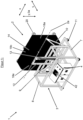
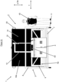
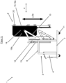
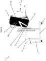
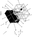
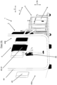
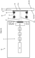
- the inventive mobile laser device 1 ( Figures 1-10 ) has a laser portal 2, preferably a transport and positioning frame 3, a control device 4 and preferably a laser protection device 5.
- Mobile means that the laser device 1 is not stationary. It can therefore be used at different locations.
- the transport and positioning frame 3 is used for setting up and preferably moving the mobile laser device 1 on the ground. As a result, the transport and positioning frame 3 is also used to position the laser device 1 and in particular the laser portal 2 attached to it relative to a glass sheet 6 to be processed.
- the transport and positioning frame 3 preferably has a base frame 7 , particularly a square one, a bearing frame 8 , particularly a cuboid one, and a portal attachment frame 9 , particularly a square one, and two portal attachment arms 10 .
- the base frame 7 is used to mount the laser device 1 on the ground. It preferably also has transport rollers 11 on the underside, so that the laser device 1 can be moved on the subsurface.
- the bearing frame 8 serves to mount the laser portal 2 and has a guide element 12 for this purpose.
- the portal attachment frame 9 is directed in a particularly vertical frame height direction 3a. and movably stored.
- the base frame 7 also preferably has drive means 13, for example a drive motor and a gear drive, with which the portal attachment frame 9 is connected so that it can be driven back and forth in the frame height direction 3a.
- the laser portal 2 is thus mounted on the bearing frame 8 so that it can be moved back and forth in the, in particular vertical, frame height direction 3a.
- the laser portal 2 can also be positioned in the frame height direction 3a manually, e.g. using a pulley mechanism.
- the portal attachment arms 10 are attached to the portal attachment frame 9 at one end.
- the laser portal 2 is fastened at the other end.
- the laser portal 2 is rotatably mounted on the portal attachment arms 10 about a preferably horizontal laser portal axis of rotation 2a.
- the laser portal 2 can be freely rotatable or driven, e.g. by an electric motor. In particular if it is freely rotatable, there are preferably locking means for locking the laser portal 2 in the desired position.
- the laser portal 2 has a laser protective hood 14, an in particular square portal base frame 15, a guide rail 16 attached thereto and a laser unit 50 mounted on the guide rail with a laser head 17 and a distance measuring device 49 for measuring the glass sheet 6 to be processed in the z-direction.
- the laser portal 2 also has an x-direction, a y-direction and a z-direction.
- the laser portal axis of rotation 2a is preferably parallel to the x-direction.
- the laser protective hood 14 preferably has two hood side walls 18a;b lying opposite one another in the x-direction, a lower hood peripheral wall 18c and an upper hood peripheral wall 18d, as well as a hood bottom wall 18e.
- the laser protection hood 14 has a hood interior 14a and a hood opening 14b.
- the hood side walls 18a; b, the lower hood peripheral wall 18c and the upper hood peripheral wall 18d and the hood bottom wall 18e surround the hood interior 14a.
- the laser protection hood 14 serves to protect the surroundings from laser radiation.
- the laser protection hood 14 consists of a laser-resistant material, preferably sheet steel.
- the portal base frame 15 has two guide bars 19a; b that are parallel to one another and spaced apart from one another and extend in the x-direction, as well as two transverse bars 19c; d that are also parallel to one another and perpendicular to the guide bars 19a; b.
- the crossbeams 19c;d thus extend in the y-direction.
- the portal base frame 15 has a frame inner side facing the laser protective hood 14 and a frame outer side facing away from it.
- the laser protective hood 14 is also fastened to the portal base frame 15 and extends away from it, in particular from the inside of the frame.
- the portal base frame 15 is thus arranged at an open end of the laser protection hood 14 . It surrounds a hood opening 14b of the laser protection hood 14.
- the portal base frame 15 has fastening means for fastening the laser device 1 to the object or component to be processed.
- the fastening means are used for fixed, ie non-displaceable and non-rotatable, but detachable fastening to the object or component to be processed.
- the portal base frame 15 preferably has several, preferably four, suction cups 20, preferably vacuum suction cups.
- the suction cups 20 are preferably attached to and extend from the outside of the frame.
- a suction cup 20 is preferably arranged in each corner area of the portal base frame 15 .
- the guide rail 16 extending in the y-direction has a rail inner side 16a facing the laser protective hood 14 and a rail outer side 16b facing away from it.
- the guide rail 16 is mounted on the two guide beams 19a;b so that it can be moved back and forth in the x-direction.
- the guide rail 16 thus extends from one guide bar 19a to the opposite guide bar 19b.
- the laser portal 2 has drive means for driving the guide rail 16 in the x-direction.
- the guide rail 16 is therefore connected to the drive means so that it can be driven back and forth in the x-direction.
- the drive means is preferably a linear drive, preferably an electric motor.
- the laser unit 50 is mounted on the guide rail 16 so that it can be moved back and forth in the y-direction. It is also arranged adjacent to the rail inside 16a. The laser unit 50 is thus arranged in the hood interior 14a of the laser protection hood 14 . Furthermore, the laser portal 2 has drive means for driving the laser unit 50 in the y-direction. The laser unit 50 is therefore connected to the drive means so that it can be driven back and forth in the y-direction relative to the guide rail 16 .
- the drive means are preferably a linear drive, preferably an electric motor, preferably a belt axle drive.
- the laser unit 50 is preferably also mounted on the guide rail 16 so that it can be moved back and forth in the z-direction.
- the laser portal 2 has drive means for driving the laser unit 50 in the z-direction.
- the laser unit 50 is therefore connected to the drive means so that it can be driven back and forth in the z-direction relative to the guide rail 16 .
- the drive means are preferably a linear drive, preferably an electric motor, in particular with a spindle axis.
- a glass sheet to be processed 6 can consist of a single pane of glass or glass plate 22 (single-pane glass). Or it can be a laminated glass panel 25 .
- a laminated glass panel 25 is understood to be a glass panel 6 formed from two or more glass panes or glass plates 22 with the same or different thicknesses, the glass panes 22 being connected to one another by an intermediate layer of plastic or a plastic film 24 ( 13 ). The glass panel 6 thus has one or more glass panes 22 .
- the glass panel 6 also has two opposite, external glass panel surfaces 6a;b.
- the glass sheet surfaces 6a;b are parallel to the plane of the glass sheet and, during processing, are preferably perpendicular to the z-direction.
- the glass panel 3 has a peripheral glass panel edge 6c, which in particular connects the two glass panel surfaces 6a; b to one another.
- a glass pane 22 also has two opposite glass pane surfaces 22a;b.
- the glass pane surfaces 22a;b are also parallel to the plane of the glass sheet and, during processing, are preferably perpendicular to the z-direction.
- the two glass panel surfaces 22a; b of the single glass panel 22 also form the glass panel surfaces 6a; b of the glass panel 6 ( figures 11 , 12 , 14 ).
- the outer glass pane surfaces 22a;b form the glass panel surfaces 6a;b of the glass panel 6 and the other glass pane surfaces 22a;b are on the inside.
- the laminated glass panel 25 therefore has more than two, in particular four, glass pane surfaces 22a;b.
- the glass panel 6 is preferably of planar design. However, it can also be curved or arched. For example, it can be designed in the shape of a cylinder jacket.
- the glass sheet 6 is therefore a flat glass element.
- the glass panel 6 can have a superficial glass pane coating 23, preferably a functional coating, on at least one of its glass pane surfaces 22a;b.
- functional coatings give glass panels 6 certain functions, e.g. filter, mirror, heating functions.
- the glass pane coating 23, in particular the functional coating can have one or more individual (functional) layers in a manner known per se. If there are several (functional) layers, there is one (Functional) layer laminate.
- the functional layers change certain properties of the glass sheet 6 or give it certain functions. The functions can be, for example, heat protection, sun protection or heating.
- the functional coating is preferably a wavelength-selective coating or low-E coating.
- the glass pane coating 23, in particular the functional coating, of the glass panel 6 preferably has at least one, preferably several, electrically conductive, metal-containing (functional) layers.
- the coating 23, in particular the functional coating can have at least one electrically semiconductive (functional) layer.
- the glass pane coating 23 preferably has at least one metallic and/or at least one ceramic layer, preferably a metal oxide layer.
- the glass pane coating 23, in particular the functional coating preferably has a metal-containing, preferably metallic (functional) layer, preferably made of silver, copper or gold.
- a (functional) layer made of metal oxide preferably consists of tin oxide.
- the ceramic (functional) layer does not have to consist of oxide ceramics. It can also be a non-oxidic ceramic (functional) layer, for example.
- the glass pane coating 23, in particular the functional coating, can also have at least one electrically insulating (functional) layer.
- the glass pane coating 23, in particular the functional coating, of the glass panel 6 thus preferably has at least one electrically conductive, metallic and/or at least one electrically conductive, preferably metal-containing, ceramic (functional) layer.
- the (functional) layers can be applied to the glass panel 6 by sputtering or wet-chemical methods.
- the glass pane coating 23, preferably the functional coating is a, preferably single-layer, pyrolytic coating. This consists of a metal oxide, preferably tin oxide.
- the production of such a glass pane coating 23 is known.
- the coating material is in vapor, liquid or solid form.
- the layer formation takes place during the manufacturing process of the glass panel 6 by a reaction of the metal-oxide coating material on the hot glass panel surface 6a (hard coating process). Glass panels 6 with such a functional coating allow short-wave radiation to pass through and reflect long-wave infrared radiation.
- the glass pane coating 23, preferably the functional coating preferably has a thickness of ⁇ 2 ⁇ m, preferably ⁇ 1 ⁇ m.
- the glass sheet 6 to be processed can also have a surface protective coating made of plastic that is known per se, in particular in the form of a non-peelable polymer coating or a peelable plastic film.
- the protective coating covers the respective glass panel surface 6a;b or, if present, the glass pane coating 23.
- the glass sheet to be processed 6 can be part of insulating glazing 26 ( 11 , 12 ) be.
- the insulating glazing 26 has at least two parallel glass panels 6 arranged at a distance from one another and a spacer frame 27 arranged between the glass panels 6, which connects the two glass panels 6 to one another in the glass panel edge area, a primary seal (not shown) and an edge seal (secondary seal ) 28 on.
- a pane interior 29 is delimited by the glass panels 6 and the spacer frame 27 .
- the primary seal is present in a manner known per se between the spacer frame 27 and the respective glass panel 6 and glues them together.
- the glass panels 6 of the insulating glazing 26 can each be a toughened glass panel 22 or a laminated glass panel 25 .
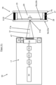
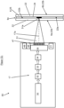
- the inventive laser head 17 ( 11-14 ) has a laser radiation source 30 for providing or generating a laser beam 31, preferably a beam shaping device 32 for geometric beam shaping, preferably an energy distribution device 33 for adjusting the energy distribution of the laser beam 31, according to the invention an optical z-focus adjustment device 34 and preferably a scanning device 35.
- the laser radiation source 30 is preferably exchangeable, so that the optimal laser radiation source 30 can be used for each application.
- a laser radiation source 30 suitable for the respective application in terms of wavelength and/or laser power and/or pulse duration is preferably used.
- the laser radiation source 30 is preferably a UV laser or an IR laser or a VIS laser.
- it can be a continuous wave laser or a pulsed laser. It is preferably a pulsed laser in which the pulse duration and/or the repetition rate can be adjusted within certain limits.
- the laser radiation source 30 is preferably a fiber laser.
- the laser radiation source 30 is preferably a laser in which the laser power can be adjusted.
- the laser power can preferably be set in the range from 5 to 1000 watts, preferably 5 to 200 watts, particularly preferably 20 to 200 watts.
- a pulsed ns fiber laser with a laser power of 100 W and a wavelength of 1 ⁇ m is used for the laser modification, the laser ablation and the laser transfer printing.
- the laser head 17 also has the beam shaping device 32 .
- the beam shaping device 32 is arranged downstream of the laser radiation source 30 and is used for geometric beam shaping of the laser beam 31 .
- the beam shaping device 32 serves to shape the laser beam 31 in such a way that it has a rectangular cross section or a linear cross section or a circular cross section.
- the beam-shaping device 32 has, in a manner known per se, a lens system, for example, preferably GRIN optics (gradient index lens optics).
- the beam shaping device 32 can preferably be brought into the beam path of the laser beam 31 and removed from it.
- the beam-shaping device 32 can preferably be pivoted into the beam path and pivoted out again.
- the beam shaping device 32 is mounted in the laser head 17 accordingly for this purpose.
- the laser head 17 preferably also has corresponding drive means with which the beam shaping device 32 can be brought into the beam path and driven away from it.
- the beam shaping device 32 can be arranged or positioned in or outside the beam path of the laser beam 31 depending on the method to be carried out and the required cross-sectional profile of the laser beam 31 .
- the beam shaping device 32 is also preferably exchangeable, so that the beam geometry to be generated can be varied.
- a plurality of beam-shaping devices 32 can also be present, which can be selectively brought into the beam path and removed from it. This can preferably be done by means of a turret driven, in particular by an electric motor.
- the laser head 17 also has the energy distribution device or beam profile shaping device 33 .
- the energy distribution device 33 is preferably arranged downstream of the geometric beam shaping device 32 and is used to adapt the energy distribution or to shape the beam profile of the laser beam 31.
- the energy distribution device 33 preferably has means for generating an annular beam profile (M-profile) or a top-hat profile usually from a Gaussian beam profile.
- the energy distribution device 33 can also be arranged or positioned in or outside the beam path of the laser beam 31, depending on the method to be carried out and the required cross-sectional profile of the laser beam 31, for which purpose appropriate adjusting means are available.
- the energy distribution device 33 is also preferably exchangeable, so that the energy distribution to be generated can be varied.
- energy distribution devices 33 can also be present, which can be selectively placed in the beam path and removed from it. This can preferably be done by means of a turret driven, in particular by an electric motor.
- the energy distribution device 33 and the beam shaping device 32 can also be combined in one device.
- the laser head 17 also has the optical z-focus adjustment device 34 according to the invention.
- the optical z-focus adjustment device 34 is preferably downstream of the energy distribution device 33 and is used for the preferably automated optical adjustment of the laser focus 31a along an optical z-axis 17a of the laser head 17 or for the optical displacement of the focus position of the laser focus 31a along the optical z-axis 17a.
- the z-focus adjustment device 34 has an optical system, preferably a lens system.
- the displacement of the laser focus 31a also takes place in particular on the basis of the measurement results of the distance measuring device 49.
- the distance measuring device 49 is used to measure the glass sheet 6 to be processed in the z-direction.
- the distance measuring device 49 preferably has a measuring device laser radiation source for generating a measuring laser beam and a laser beam detector, preferably a line sensor, for detecting laser beam reflections of the measuring laser beam.
- the distance measuring device 49 irradiates the glass sheet 6 to be processed or at least the region of the glass sheet 6 to be processed using the measuring laser beam, the measuring laser beam forming an angle with the surface normal to the glass sheet surfaces 6a;b.
- the measuring laser beam is reflected by the glass panel surfaces 6a;b or the glass pane surfaces 22a;b and the reflected laser beam reflections are detected by the laser beam detector.
- the measuring laser beam is preferably linear, for which purpose the distance measuring device 49 has means known per se for shaping the measuring laser beam.
- a laser beam reflection is generated on each glass pane surface 22a;b, so that two reflections are generated for each individual glass pane 22 of the incident laser beam, namely on the one hand on the front glass pane surface 22a in the direction of incidence and after passage through the glass pane 22 also on the rear glass pane surface 22b. Two laser beam reflections are therefore detected in the laser beam detector for each individual glass pane 22 after the laser beam reflections have struck.
- the distances between the glass pane surfaces 22a;b are determined and their exact position is seen in the z-direction. This is important for the exact positioning of the laser focus 31a in the z-direction.
- the laser beam 31 is important to focus the laser beam 31 on the correct plane depending on the process to be performed.
- the laser beam 31 must be focused on the inner or outer glass sheet surface 6a;b, the glass pane coating 23 or the plastic intermediate layer 24, which will be discussed in more detail below.
- the focus may have to be adjusted parallel to the optical z-axis 17 extending in the z-direction during the processing of the glass sheet 6 due to unevenness of the glass sheet surface 6a.
- the number of glass panes 22 arranged one behind the other can also be determined from the number of reflections if this is not known.
- the distance measuring device 49 is preferably connected to the control device 4, which processes the measurement data.
- the distance measuring device can also have means for processing the measurement data.
- the laser head 17 also has the scanning device 35 .
- the scanning device 35 is preferably arranged downstream of the optical z-focus adjustment device 34 and is used to move the laser beam 31 in one scan field.
- the laser beam 31 can be moved in the y-direction and in the x-direction by means of the scanning device 35 .
- the scanning device 35 has scanning optics in a manner known per se.
- the scanning optics are preferably at least two adjustable mirrors.
- the scan field is, for example, 100 mm x 100 mm.
- the laser beam 31 can be moved in the y-direction and in the x-direction in such a way that it remains parallel to the optical z-axis 17a or is deflected in relation to it.
- the scanning device 35 has an objective 47 .
- the lens 47 preferably has a short focal length. It preferably has a focal length of 20 to 200 mm, preferably 80 to 160 mm. This achieves strong focusing and a small extension of the laser focus 31a in depth or in the direction of the optical z-axis 17a. In particular, the depth of the laser focus 31a is constant in the range of approx. +/-1 mm. This ensures that, e.g. in a laminated glass panel 25 or insulating glazing 26, only the layer 23; 24 to be processed is modified or removed by means of the laser energy and the remaining areas of the glass panel 6 remain unchanged.
- the lens 47 can preferably be exchanged so that, among other things, the working distance can be varied and adjusted.
- the lens 47 can preferably be unscrewed.
- the laser device 1 according to the invention is also used to coat a glass sheet surface 6a of the glass sheet 6 by means of laser transfer printing ( 14 ).
- the laser head 17 has a laser transfer printing device 36 .
- the laser transfer printing device 36 has a donor or carrier medium 37 , preferably in the form of a strip, in particular a carrier film in the form of a strip, a plurality of guide rollers 38 and a pressure frame 39 .
- the laser transfer printing device 36 can preferably be brought into the beam path of the laser beam 31 and removed from it.
- the laser transfer printing device 36 can preferably be swiveled into the beam path and swiveled out again.
- the laser transfer printing device 36 is mounted accordingly for this purpose.
- the laser head 17 preferably also has corresponding drive means with which the laser transfer printing device 36 can be brought into the beam path and driven in a removable manner.
- the laser transfer printing device 36 can also be replaceable or only inserted into the laser head 17 when required.
- the dispenser or carrier medium 37 is preferably a coated plastic film, preferably made of PET.
- the carrier medium 37 is preferably in the form of a strip.
- the carrier medium 37 has a superficial carrier medium coating made of coating material.
- the carrier medium coating preferably has at least one metallic layer and/or at least one ceramic layer, preferably a metal oxide layer.
- the carrier medium coating is preferably formed in one layer. It particularly preferably consists of a metallic material, in particular silver, copper or gold.
- the carrier medium coating can also be a low-E coating.
- the carrier medium coating preferably has a thickness of ⁇ 5 ⁇ m.
- the carrier medium 37 is preferably exchangeable. As a result, depending on the application, different carrier media with different carrier medium coatings can be used.
- the pressure frame 39 is used to press the strip-shaped carrier medium 37 against the glass sheet 6 to be marked.
- the pressure frame 39 is preferably transparent to the laser radiation.
- the pressure frame 39 has an opening which exposes the area of the glass sheet 6 to be coated.
- the carrier medium 37 in the form of a strip is also guided around the rotatably drivable guide rollers 38 and is moved by these, if desired, relative to the laser beam 31 and the pressure frame 39 .
- the laser head 17 has appropriate drive means for driving the guide rollers 38 about their roller axis.
- the laser unit 50 also preferably has an x-y measuring device 46, preferably a camera, for measuring the external dimensions of the glass sheet 6 to be processed in the x and y direction, in particular for measuring the glass edge 6c in the x and y direction .
- the camera preferably has image recognition software that is known per se.
- the laser unit 50 preferably has a suction device 21 for sucking off material removed by means of the laser radiation.
- All components of the laser unit 50 are preferably mounted on a base plate of the laser unit 50.
- the laser device 1 also has the control device 4 for the selection and automated control of the different processing methods.
- the control device 4 has a program for controlling the respective processing method.
- the control device 4 is preferably mounted on the transport and positioning frame 3 .
- the control device 4 also preferably has an operating or input field 42 for operation by an operator 43 .
- the laser protection device 5 has a laser protection element 40, preferably a laser protection curtain 41, and a detection device for detecting the presence of the laser protection element 40.
- the detection device is set up to detect whether the laser protection element 40, preferably the laser protection curtain 41, is present and correctly positioned on the side of the glass panel 6 opposite the laser head 17.
- the detection device has a number of sensors, preferably magnetic sensors and/or radio sensors.
- the detection device is connected to the control device 4 .
- the control device 4 is preferably set up in such a way that the laser radiation source 30 can only be started and/or operated if the detection device detects correct positioning of the laser protection element 40, preferably the laser protection curtain 41.
- the control device 4 is set up in such a way that the laser radiation source 30 is automatically switched off when the laser protection element 40 is no longer correctly positioned.
- the laser protection element 40 preferably the laser protection curtain 41, also has attachment means for attachment to the respective object, e.g.
- the fastening means are preferably suction cups, in particular vacuum suction cups, or magnetic fastening means.
- the laser device 1 is supplied with energy either via the connection to a stationary power supply system or the laser device 1 is self-sufficient and has its own energy supply device (not shown).
- Your own energy supply device is preferably a generator or a battery.
- the generator is preferably mechanically decoupled from the transport and positioning frame 3 in order to avoid vibrations of the transport and positioning frame 3 during lasering.
- the laser device 1 according to the invention is also supplied with compressed air either via the connection to a stationary compressed air source or the laser device 1 is self-sufficient and has its own compressed air source (not shown).
- the compressed air source is preferably used to operate the vacuum suction cups and/or to press the pressure frame 39 during laser transfer printing.
- the mobile laser device 1 is first transported to the object to be processed or to the place of use. This can be done, for example, in a pickup truck 48 ( 6 ) take place.
- the laser device 1 is preferably disassembled, preferably into three parts, namely the transport and positioning frame 3, the laser portal 2 and the laser safety device 5.
- the laser device 1 is then assembled at the place of use, in particular the assembly of the laser portal 2 on the transport and Positioning frame 3. If necessary, the mobile laser device 1 is also connected to the external energy supply device and/or the external compressed air source.
- the assembled laser device 1 is then moved by means of the transport and positioning frame 3 to the glass sheet 6 to be processed.
- ( 9 , 10 ) is a glass panel 6 of a train window 45 of a train 44.
- the laser device 1 is positioned relative to the object, for example by the operator 43, by means of the transport and positioning frame 3 and, if necessary, the laser portal 2 is pivoted about the laser portal axis of rotation 2a.
- the laser portal 2 is attached by means of the suction cups 20 to the object having the glass sheet 6 to be processed in a detachable but non-displaceable and non-rotatable manner.
- the laser portal 2 is attached to a train outer skin 44a of the train 44 .
- it can also be attached directly to the glass panel 6 .
- the laser portal 2 is arranged in such a way that it surrounds the train window 45 or the glass panel 6 .
- the laser protection element 40 is positioned on the side of the glass panel 6 opposite the laser portal 2 .
- the laser protection element 40 preferably the laser protection curtain 41, is attached to the inner skin of the train 44b in such a way that it covers the train window 45 from the inside ( 10 ). The presence and the correct positioning of the laser protection element 40 are automatically detected by means of the detection device and corresponding information is sent to the control device 4 .
- the external dimensions of the glass sheet 6 to be processed are preferably measured in the x and y directions.
- the laser head 17 is moved in the x and y direction over the glass panel 6 and a 2D image of the glass panel 6 is created, preferably by means of the x-y measuring device 46, preferably the camera.
- the x and y coordinates of the outer dimensions of the glass sheet 6 are determined. This information is particularly important for precise x/y positioning of the laser beam 31 in relation to the glass sheet 6 during the laser process.
- the xy measuring device 46 preferably the camera, is therefore connected to the control device 4 and transmits the coordinates or the created 2D image to it.
- the laser focus 31a must be positioned differently in the z-direction.
- the laser beam 31 must be focused on the glass pane coating 23, the plastic intermediate layer 24, the interior of the glass sheet 6 or the glass sheet surface 6a;b or an inner glass pane surface 22a;b.
- the laser focus 31a must be adjusted accordingly during processing.
- the glass sheet 6 is measured in the z-direction by means of the distance measuring device 49 as described above. This can take place during the measurement of the glass sheet 6 in the x/y direction, before or after it.
- the measurement in the z-direction can also take place online during the processing of the glass sheet 6 in that the distance measuring device 49 is in front of the laser beam 31 and measures the area to be processed directly before it is processed with the laser beam 31 .
- the distance measuring device 49 can be moved and driven on the laser unit 50 in the x and y direction.
- one or more curvatures or unevennesses of the glass sheet 6 and/or the glass sheet surface 6a;b or glass pane surface 22a;b and/or thickness differences are also determined by means of the distance measuring device 49.
- a 3D image of the glass sheet 6 to be processed is preferably created, in particular by the control device 4.
- the x and y coordinates are calculated on the basis of the x and y coordinates of the outer dimensions of the glass panel 6 and the travel path of the distance measuring device 49 .
- the laser head 17 Before the start of the machining process, the laser head 17 is first positioned accordingly in the x, y and z direction. For this purpose, the laser head 17 is moved along the guide rail 16 in the y-direction and/or moved with the guide rail along the guide beams 19a;b in the x-direction and/or moved in the z-direction relative to the guide rail 16 to the 0 position or starting position .
- the laser focus 31a is preferably initially focused on the glass sheet surface 6a facing the laser head 17 by positioning the laser head in the z-direction. Laser beam 31 is then focused further via optical z-focus adjustment device 34. In particular, laser focus 31a is adjusted or shifted along optical z-axis 17a during processing via optical z-focus adjustment device 34. Adjustment or shifting takes place in an automated manner, preferably on the basis of the previously determined x, y and z coordinates, in particular the 3D image, of the glass panel 6 or glass panel surface(s) 6a;b or glass pane surface(s) 22a;b.
- the laser head 17 is also moved in the x and/or y direction relative to the glass sheet 6 in a manner known per se and/or the laser beam 31 is scanned in the x and/or y direction by means of the scanning device 35 relative to the laser head 17 procedure. Due to the additional movement of the laser beam 31 by means of the scanning device 35, the laser beam 31 can, for example, be broken down into several beams.
- the laser head 17 can, for example, be moved step by step in a manner known per se (tiling mode) or continuously.
- the laser device 1 has means for carrying out various processing methods:
- the laser device 1 is used to at least partially remove the surface coating 23 of a glass pane 6 by means of the laser beam 31 (laser ablation) ( 11 ).
- the laser beam 31 is focused onto the coating 23 of the glass pane.
- the laser beam 31 is focused on the glass pane coating 23 of the inner glass panel surface 6b of a glass panel 6 of insulating glazing 26 .
- Individual or all layers of the glass pane coating 23 are completely removed, in particular evaporated or burned, at least in regions by means of the laser beam 31 .
- the glass panel 6 has an additional protective coating made of plastic, this can be removed beforehand, in particular mechanically or by means of laser radiation, or at the same time or together with the coating 23 on the glass pane.
- the material removed by means of laser ablation is also sucked off by means of the suction device 21 . This is particularly the case when the processed glass sheet surface 6a; b is exposed or is accessible from the outside.
- a mobile radio-permeable structure can be produced in a glass panel 6, preferably a glass panel 6 of a train window 45.
- a radar-damping structure can be produced in a glass panel 6, preferably a glass panel 6 of a train window 45, by means of the laser ablation of the glass pane coating 23 in the glass pane coating 23.
- a bird protection structure can also be produced. This is an optical structure or an optical pattern that birds perceive as a clear obstacle.
- An electronic structure for example an alarm loop or a switch or an electronic structure of a heated glass, can also be produced.
- Edge deletion is preferably carried out according to FIG DE 10 2018 107 697 A1 .
- the protective coating and/or the functional coating is removed by means of the laser radiation.
- the edge deletion takes place according to the DE 10 2019 213 603 A1 , whereby coating residues are removed by means of laser radiation.
- a marking preferably a machine-readable marking, preferably a machine-readable code, preferably a data matrix code (DCM) or a barcode or a QR code
- DCM data matrix code
- QR code a barcode or a QR code
- the laser device 1 is used to modify the superficial glass pane coating 23 of a glass panel 6 by means of the laser beam 31 (laser modification) ( 12 ).
- Laser modification therefore means changing or modifying the electrical and/or optical and/or mechanical properties of individual or all layers of the glass pane coating 23.
- the laser beam 31 is focused on the glass pane coating 23, for example on the glass pane coating 23 of the inner glass panel surface 6b of a glass panel 6 of insulating glazing 26.
- the irradiation therefore takes place below the removal threshold. This means that no material is removed during the modification.
- the composition of the glass pane coating 23 is changed chemically and/or physically during the modification.
- the glass pane coating 23 can have layer(s) of atomic silver, which are changed under the action of the laser beam 31 in such a way that the silver atoms agglomerate and form nanoparticles. As a result, the layer of atomic silver loses its electrical conductivity and becomes insulating.
- the layer(s) of atomic silver are preferably embedded in protective layers, preferably electrically insulating layers, e.g. made of metal oxide, in particular tin oxide.
- the laser power and/or the wavelength of the laser beam 31 is thus adjusted in each case depending on the desired result and depending on the layer(s) to be processed.
- the laser modification can preferably according to the DE 10 2005 025 982 A1 take place.
- the protective coating can be removed before the laser modification, eg also by means of laser radiation and/or mechanically. Or the protective coating is removed by the laser radiation during the laser modification by removed by the laser radiation, preferably burned.
- the laser modification is analogous to that in FIG DE 10 2018 207 181 A1 described.
- a mobile radio-permeable structure can also be produced in the glass pane coating 23 in a glass panel 6, preferably a glass panel 6 of a train window 45.
- a radar-damping structure can be produced in a glass panel 6, preferably a glass panel 6 of a train window 45.
- a bird protection structure can also be produced by means of the laser modification.
- An electronic structure for example an alarm loop or a switch or an electronic structure of a heated glass, can also be produced.
- a marking preferably a machine-readable marking, preferably a machine-readable code, preferably a data matrix code (DCM) or a barcode or a QR code
- DCM data matrix code
- QR code a barcode or a QR code
- decorative elements can be created.
- the laser device 1 according to the invention is used to coat a glass sheet surface 6a of the glass sheet 6 by means of laser transfer printing ( 14 ).
- laser transfer printing an electronic Structure or a colored structure, in particular a colored marking applied.
- the structure is produced by applying a preferably electrically conductive coating material to the glass sheet surface 6a using the laser transfer printing device 36.
- the glass sheet surface 6a is therefore coated with the coating material.
- the carrier medium 37 is pressed with its coated side by means of the pressure frame 39 against the glass sheet surface 6a of the glass sheet 6 to be coated. As a result, the carrier medium coating is pressed against the glass panel 6 . Then, by means of the laser beam 31 focused on the carrier medium coating, coating material from the carrier medium coating is transferred to the glass panel 6 and fixed to it. Because the laser radiation is absorbed by the coating material, this is detached from the carrier medium 37 and conveyed onto the glass sheet surface 6a to be coated.
- the carrier medium 37 can be moved relative to the laser beam 31 by means of the guide rollers 38 in such a way that the laser beam 31 always hits coated carrier medium 37 or the carrier medium coating and not areas in which the carrier medium coating has already (partially) been removed.
- the laser beam 31 can be moved in the x and/or y direction relative to the carrier medium 37 .
- the movement of the laser beam 31 in the x and/or y direction relative to the carrier medium 37 preferably takes place by means of the scanning device 35. This is known per se.
- the structure is preferably prepared according to the method according to FIG DE 10 2005 026 038 A1 or the DE 10 2011 085 714 A1 upset.
- the structure is preferably prepared using the method according to FIG DE 10 2018 207 181 A1 upset.
- the protective coating is removed by means of laser radiation, preferably burned or burned away, and in the same operation coating material from the donor or carrier medium 37 is applied, in particular printed, to an exposed surface of the glass sheet 6 by means of the laser radiation, which was previously underneath of the protective coating of the glass sheet 6 has been located.
- the carrier medium 37 having the surface carrier medium coating made of the coating material is brought into contact with the protective coating of the glass sheet 6 with its coated side in the area to be coated.
- the protective coating is then removed by means of the laser radiation and, as described, the carrier medium coating material is transferred from the carrier medium coating to the glass sheet surface 6a and fixed to it.
- the structure can also be applied to a coated glass sheet surface 6a;b by means of laser transfer printing.
- the structure can be applied to the glass pane coating 23 .
- a bird protection structure can be produced by means of laser transfer printing.
- An electronic structure for example an alarm loop or a switch or an electronic structure of a heated glass, can also be created.
- conductor tracks can be applied.
- a marking preferably a machine-readable marking, preferably a machine-readable code, preferably a data matrix code (DCM) or a barcode or a QR code can also be applied.
- DCM data matrix code
- QR code a barcode or a QR code
- decorative elements and frames can be applied.
- the aforementioned methods can also be combined with one another as desired and the structure can be produced by a combination of one or more of the methods described above.
- the glass pane coating 23 can be removed and/or modified and a further structure can be applied to it by means of laser transfer printing.
- the laser device 1 according to the invention is preferably used to modify the plastic intermediate layer 24 of a laminated glass panel 25 by means of the laser beam 31 or to burn it ( 13 ).
- the optical and/or mechanical properties of the plastic intermediate layer 24 are modified during the modification. In particular, it becomes discolored.
- the intermediate plastic layer 24 is preferably incinerated
- the laser beam 31 is focused on the plastic intermediate layer 24, i.e. between the two glass panes 22.
- a marking or a decorative element can also be produced by means of the laser treatment of the plastic intermediate layer 24 .
- an emergency exit window can be created that can be removed.
- the laser device 1 according to the invention can also be used for laser-induced generation of an internal marking in the glass sheet 6, preferably by forming color centers, preferably by means of ultra-short pulsed laser radiation. be used.
- a different laser radiation source 30 must be used than in the previously described method.
- the laser device 1 according to the invention can also be used for laser-induced generation of a surface marking on a glass sheet surface 6a or glass pane surface 22a;b by laser engraving, preferably by means of ultra-short pulsed laser radiation Glass panel surface 6a;b or glass pane surface 22a;b removed by laser radiation.
- the laser device 1 according to the invention can also be used to erase the marking by means of laser radiation.
- the marking and / or deleting the marking as in the DE 10 2020 215 234 A1 or the DE 10 2020 215 235 A1 described.
- the advantage of the mobile laser device 1 according to the invention is that it can be used flexibly for different processing methods and at different locations. It is also easy to transport and can therefore be used to process glass panels 6 that have already been installed. As already explained, glass panels 6 of a train window 45 or a window in office buildings can be processed in the installed state.
- the mobile laser device 1 according to the invention can therefore be used very flexibly.
- the laser device 1 can also be converted quickly and easily due to the numerous exchangeable components.
- the laser portal 2 can be decoupled from the transport and positioning frame 3 during the processing of the glass sheet 6 .
- the transport and positioning frame 3 can also be dispensed with entirely and the mobile laser device 1 can be transported by other means of transport to the glass sheet 6 to be processed, e.g. by means of a drone.
- the transport and positioning frame 3 does not have to be rollable, but can also be moved by means of an air cushion track.
- control device 4 does not have to be mounted on the transport and positioning frame 3 . It is only important that the control device 4 is connected to the respective parts or components of the laser portal 2, in particular the laser head 17 and the drive means for driving the laser head 17 in the x, y and z directions, in order to control them .
- the connection can be wired or, if this is not the case, e.g. also a radio connection.
- the respective assemblies or components then have corresponding receivers.
- the basic laser unit 50 prefferably has a plurality of laser heads 17, preferably two laser heads 17.
- the basic laser unit 50 can also have several, preferably two, distance measuring devices 49 .
- the structure of the glass sheet 6 in the thickness direction i.e. in particular the thickness of the glass sheet 6 and/or the individual glass panes 22 and the plastic intermediate layer 24 are known. Because then their position in the z-direction can be calculated.
Landscapes
- Physics & Mathematics (AREA)
- Optics & Photonics (AREA)
- Engineering & Computer Science (AREA)
- Mechanical Engineering (AREA)
- Plasma & Fusion (AREA)
- Chemical & Material Sciences (AREA)
- Robotics (AREA)
- General Chemical & Material Sciences (AREA)
- Chemical Kinetics & Catalysis (AREA)
- Life Sciences & Earth Sciences (AREA)
- Toxicology (AREA)
- Health & Medical Sciences (AREA)
- Geochemistry & Mineralogy (AREA)
- Materials Engineering (AREA)
- Organic Chemistry (AREA)
- Oil, Petroleum & Natural Gas (AREA)
- Laser Beam Processing (AREA)
Applications Claiming Priority (1)
| Application Number | Priority Date | Filing Date | Title |
|---|---|---|---|
| DE102021215023.3A DE102021215023B3 (de) | 2021-12-23 | 2021-12-23 | Mobile Laservorrichtung und deren Verwendung sowie Verfahren zur Bearbeitung einer Glastafel |
Publications (3)
| Publication Number | Publication Date |
|---|---|
| EP4201575A1 true EP4201575A1 (fr) | 2023-06-28 |
| EP4201575C0 EP4201575C0 (fr) | 2026-04-15 |
| EP4201575B1 EP4201575B1 (fr) | 2026-04-15 |
Family
ID=84330534
Family Applications (1)
| Application Number | Title | Priority Date | Filing Date |
|---|---|---|---|
| EP22206384.4A Active EP4201575B1 (fr) | 2021-12-23 | 2022-11-09 | Dispositif laser et son utilisation pour le traitement d'un panneau de verre |
Country Status (5)
| Country | Link |
|---|---|
| US (1) | US20250135575A1 (fr) |
| EP (1) | EP4201575B1 (fr) |
| CA (1) | CA3239966A1 (fr) |
| DE (1) | DE102021215023B3 (fr) |
| WO (1) | WO2023117195A1 (fr) |
Families Citing this family (4)
| Publication number | Priority date | Publication date | Assignee | Title |
|---|---|---|---|---|
| EP4251363B1 (fr) | 2020-11-30 | 2026-08-05 | AGC Glass Europe | Appareil laser pour être monté sur une fenêtre montée in situ comprenant une jupe et méthode associée, et utilisation d'une jupe |
| DE102023205505B3 (de) | 2023-06-13 | 2024-09-05 | Hegla Boraident Gmbh & Co. Kg | Lasertransferdruckvorrichtung und deren Verwendung sowie Verfahren zum Beschichten einer Glastafel mittels Lasertransferdruck |
| USD1135976S1 (en) * | 2024-03-19 | 2026-07-21 | Shenzhen Henghao Laser Technology Co., Ltd | Laser cutting machine |
| USD1108506S1 (en) * | 2024-08-29 | 2026-01-06 | Shanghai Oceania International Co., Ltd. | Laser engraving machine |
Citations (33)
| Publication number | Priority date | Publication date | Assignee | Title |
|---|---|---|---|---|
| JPS613693A (ja) | 1984-06-15 | 1986-01-09 | Mitsubishi Electric Corp | レ−ザ加工機 |
| DE19629037C1 (de) | 1996-07-18 | 1997-07-31 | Erwin Martin Heberer | Wandelement für eine einen Arbeits- oder Wirkungsbereich umgebende Schutzvorrichtung gegen Laserstrahlen einer Laserquelle |
| WO1999052670A1 (fr) | 1998-04-14 | 1999-10-21 | Fraunhofer-Gesellschaft zur Förderung der angewandten Forschung e.V. | Dispositif et procede de structuration superficielle de revetements de sols poses |
| US20040041105A1 (en) | 2000-02-16 | 2004-03-04 | Ultratech Stepper, Inc. | Radiation shield device and method |
| DE202006006823U1 (de) | 2006-04-27 | 2006-08-24 | Frenzelit-Werke Gmbh & Co. Kg | Laserschutzvorrichtung |
| US20060266920A1 (en) | 2005-05-31 | 2006-11-30 | David Pileri | System and method for errant laser beam detection using a continuity circuit adjacent an optic |
| DE102005026038A1 (de) | 2005-06-03 | 2006-12-07 | Boraglas Gmbh | Verfahren zur Markierung von Objektoberflächen |
| DE102005025982A1 (de) | 2005-06-03 | 2006-12-07 | Martin-Luther-Universität Halle-Wittenberg | Low-E-Schichsysteme mit farbigen Strukturen und Verfahren zur Erzeugung der Strukturen |
| DE102006049946A1 (de) | 2006-10-19 | 2008-04-24 | Boraglas Gmbh | Verfahren und Sensoranordnung zur Untersuchung von Glasscheiben, insbesondere wenigstens eines Glasscheibenstapels |
| US20080112447A1 (en) | 2006-11-10 | 2008-05-15 | Jenoptik Automatisierungstechnik Gmbh | Laser protection arrangement with safety cutoff |
| EP2153931A1 (fr) | 2008-08-05 | 2010-02-17 | Antares GmbH | Dispositif, procédé de procédés de représentation d'un dispositif destiné à la protection de rayons laser |
| EP2338635A1 (fr) | 2009-12-22 | 2011-06-29 | Antares GmbH | Dispositif et procédé de protection laser par mesure d'oscillation |
| US8416820B1 (en) | 2011-11-09 | 2013-04-09 | Lasermet Limited | Active laser guarding system |
| DE102011085714A1 (de) | 2011-11-03 | 2013-05-08 | Boraident Gmbh | Verfahren und Vorrichtung zur Erzeugung einer lasergestützten elektrisch leitfähigen Kontaktierung einer Objektoberfläche |
| DE102012106278A1 (de) | 2012-04-13 | 2013-10-17 | Scansonic Mi Gmbh | Laserschutzvorrichtung zum Erfassen von Laserstrahlung |
| DE202014006477U1 (de) | 2014-08-08 | 2014-09-05 | Hochschule Mittweida (Fh) | Schutzwand für Laserstrahlen wenigstens einer Lasereinrichtung |
| US8927069B1 (en) | 2013-10-02 | 2015-01-06 | Eritek, Inc. | Method and apparatus for improving radio frequency signal transmission through low-emissivity coated glass |
| EP2905525A1 (fr) | 2014-01-15 | 2015-08-12 | Martin Fitz | Système avec au moins une zone d'action pour au moins un laser |
| DE102014002644A1 (de) | 2014-02-27 | 2015-08-27 | Boraident Gmbh | Verfahren zur Herstellung einer Vogelschutzvorrichtung und Vogelschutzglas |
| DE102014014889A1 (de) | 2014-10-13 | 2016-04-14 | Boraident Gmbh | Verfahren zur Herstellung eines Fassadenelementes aus Glas zur Abschirmung von Licht und Fassadenelement |
| DE202017100227U1 (de) | 2017-01-17 | 2017-02-16 | JUTEC Hitzeschutz und Isoliertechnik GmbH | Laserschutzvorrichtung zur Abschirmung mindestens einer Laserlichtquelle mit flächig ausgebildeten, flexiblen Wandelementen |
| DE102016125544A1 (de) | 2016-12-23 | 2018-06-28 | Glaswerke Arnold Gmbh & Co. Kg | Verfahren zur Herstellung einer biozid wirkenden Glasoberfläche eines Kalk-Natronsilicatglases |
| DE202018104113U1 (de) | 2018-07-17 | 2018-09-03 | JUTEC Hitzeschutz und Isoliertechnik GmbH | Laserschutzvorrichtung zur Abschirmung mindestens einer Laserlichtquelle mit flächig ausgebildeten, flexiblen Verkleidungsteilen |
| DE102018107697A1 (de) | 2018-03-29 | 2019-10-02 | Hegla Boraident Gmbh & Co. Kg | Entschichtungseinrichtungen und -verfahren zum Entschichten von Glastafeln, vorzugsweise Verbundglastafeln |
| DE102018207181A1 (de) | 2018-05-08 | 2019-11-14 | Hegla Boraident Gmbh & Co. Kg | Verfahren zum Markieren von Glastafeln, vorzugsweise von Einscheiben-Sicherheitsglastafeln |
| DE102018217970A1 (de) | 2018-10-19 | 2020-04-23 | Hegla Boraident Gmbh & Co. Kg | Verfahren zur Herstellung einer elektronischen Struktur auf einer Glasscheibe sowie Glastafel mit mindestens einer derartigen Glasscheibe |
| DE202020107266U1 (de) | 2020-08-27 | 2021-03-09 | Alotec Dresden Gmbh | Roboterbasierte Laserbearbeitungsanlage |
| DE102019213603A1 (de) | 2019-09-06 | 2021-03-11 | Hegla Boraident Gmbh & Co. Kg | Entschichtungseinrichtung und -verfahren zum Entschichten von Glasscheiben, sowie Verfahren zur Herstellung von Glasscheiben für Stufenglas, Stufenglas und Stufenglasfenster |
| US20210205920A1 (en) * | 2017-10-25 | 2021-07-08 | Nikon Corporation | Processing apparatus, and manufacturing method of movable body |
| WO2021165064A1 (fr) * | 2020-02-18 | 2021-08-26 | Agc Glass Europe | Appareil pour éliminer au moins une partie d'au moins un système de revêtement présentant une fenêtre à vitrages multiples et procédé associé |
| WO2021239597A1 (fr) | 2020-05-26 | 2021-12-02 | Agc Glass Europe | Appareil et procédé d'élimination d'au moins une partie d'au moins un système de revêtement présent dans une fenêtre à vitres multiples montée sur un objet fixe ou mobile |
| DE102020215235A1 (de) | 2020-12-02 | 2022-06-02 | Hegla Boraident Gmbh & Co. Kg | Verfahren zum Erzeugen von farbigen, 3-dimensionalen Strukturen in Glaselementen |
| DE102020215234A1 (de) | 2020-12-02 | 2022-06-02 | Hegla Boraident Gmbh & Co. Kg | Verfahren zum Löschen einer laserinduzierten Markierung von Glastafeln sowie Verfahren und Vorrichtungen zum Markieren und Entmarkieren von Glastafeln, vorzugsweise von Basisglastafeln, bevorzugt von Floatglastafeln |
Family Cites Families (3)
| Publication number | Priority date | Publication date | Assignee | Title |
|---|---|---|---|---|
| DE202004004382U1 (de) | 2004-03-18 | 2005-04-21 | Horlacher, Tomas | Schweißhilfsvorrichtung |
| DE102014011569B4 (de) | 2014-08-02 | 2016-08-18 | Precitec Optronik Gmbh | Verfahren zum Messen des Abstands zwischen einem Werkstück und einem Bearbeitungskopf einer Laserbearbeitungsvorrichtung |
| CN109048068A (zh) | 2018-09-20 | 2018-12-21 | 孟凡森 | 一种便于移动的激光清洗设备 |
-
2021
- 2021-12-23 DE DE102021215023.3A patent/DE102021215023B3/de active Active
-
2022
- 2022-11-09 WO PCT/EP2022/081267 patent/WO2023117195A1/fr not_active Ceased
- 2022-11-09 EP EP22206384.4A patent/EP4201575B1/fr active Active
- 2022-11-09 CA CA3239966A patent/CA3239966A1/fr active Pending
- 2022-11-09 US US18/722,724 patent/US20250135575A1/en active Pending
Patent Citations (36)
| Publication number | Priority date | Publication date | Assignee | Title |
|---|---|---|---|---|
| JPS613693A (ja) | 1984-06-15 | 1986-01-09 | Mitsubishi Electric Corp | レ−ザ加工機 |
| DE19629037C1 (de) | 1996-07-18 | 1997-07-31 | Erwin Martin Heberer | Wandelement für eine einen Arbeits- oder Wirkungsbereich umgebende Schutzvorrichtung gegen Laserstrahlen einer Laserquelle |
| WO1998003815A2 (fr) | 1996-07-18 | 1998-01-29 | Erwin Martin Heberer | Element mural pour un dispositif de protection assurant une protection contre les faisceaux laser d'une source laser et entourant une zone de travail ou une zone fonctionnelle |
| WO1999052670A1 (fr) | 1998-04-14 | 1999-10-21 | Fraunhofer-Gesellschaft zur Förderung der angewandten Forschung e.V. | Dispositif et procede de structuration superficielle de revetements de sols poses |
| US20040041105A1 (en) | 2000-02-16 | 2004-03-04 | Ultratech Stepper, Inc. | Radiation shield device and method |
| US20060266920A1 (en) | 2005-05-31 | 2006-11-30 | David Pileri | System and method for errant laser beam detection using a continuity circuit adjacent an optic |
| DE102005025982A1 (de) | 2005-06-03 | 2006-12-07 | Martin-Luther-Universität Halle-Wittenberg | Low-E-Schichsysteme mit farbigen Strukturen und Verfahren zur Erzeugung der Strukturen |
| DE102005026038A1 (de) | 2005-06-03 | 2006-12-07 | Boraglas Gmbh | Verfahren zur Markierung von Objektoberflächen |
| DE202006006823U1 (de) | 2006-04-27 | 2006-08-24 | Frenzelit-Werke Gmbh & Co. Kg | Laserschutzvorrichtung |
| DE102006049946A1 (de) | 2006-10-19 | 2008-04-24 | Boraglas Gmbh | Verfahren und Sensoranordnung zur Untersuchung von Glasscheiben, insbesondere wenigstens eines Glasscheibenstapels |
| US20080112447A1 (en) | 2006-11-10 | 2008-05-15 | Jenoptik Automatisierungstechnik Gmbh | Laser protection arrangement with safety cutoff |
| EP2153931A1 (fr) | 2008-08-05 | 2010-02-17 | Antares GmbH | Dispositif, procédé de procédés de représentation d'un dispositif destiné à la protection de rayons laser |
| EP2338635A1 (fr) | 2009-12-22 | 2011-06-29 | Antares GmbH | Dispositif et procédé de protection laser par mesure d'oscillation |
| DE102011085714A1 (de) | 2011-11-03 | 2013-05-08 | Boraident Gmbh | Verfahren und Vorrichtung zur Erzeugung einer lasergestützten elektrisch leitfähigen Kontaktierung einer Objektoberfläche |
| US8416820B1 (en) | 2011-11-09 | 2013-04-09 | Lasermet Limited | Active laser guarding system |
| DE102012106278A1 (de) | 2012-04-13 | 2013-10-17 | Scansonic Mi Gmbh | Laserschutzvorrichtung zum Erfassen von Laserstrahlung |
| DE102012106277A1 (de) | 2012-04-13 | 2013-10-17 | Scansonic Mi Gmbh | Laserschutzvorrichtung zum Abschirmen von Laserstrahlung |
| US8927069B1 (en) | 2013-10-02 | 2015-01-06 | Eritek, Inc. | Method and apparatus for improving radio frequency signal transmission through low-emissivity coated glass |
| EP2905525A1 (fr) | 2014-01-15 | 2015-08-12 | Martin Fitz | Système avec au moins une zone d'action pour au moins un laser |
| DE102014002644A1 (de) | 2014-02-27 | 2015-08-27 | Boraident Gmbh | Verfahren zur Herstellung einer Vogelschutzvorrichtung und Vogelschutzglas |
| DE202014006477U1 (de) | 2014-08-08 | 2014-09-05 | Hochschule Mittweida (Fh) | Schutzwand für Laserstrahlen wenigstens einer Lasereinrichtung |
| DE102014014889A1 (de) | 2014-10-13 | 2016-04-14 | Boraident Gmbh | Verfahren zur Herstellung eines Fassadenelementes aus Glas zur Abschirmung von Licht und Fassadenelement |
| DE102016125544A1 (de) | 2016-12-23 | 2018-06-28 | Glaswerke Arnold Gmbh & Co. Kg | Verfahren zur Herstellung einer biozid wirkenden Glasoberfläche eines Kalk-Natronsilicatglases |
| DE202017100227U1 (de) | 2017-01-17 | 2017-02-16 | JUTEC Hitzeschutz und Isoliertechnik GmbH | Laserschutzvorrichtung zur Abschirmung mindestens einer Laserlichtquelle mit flächig ausgebildeten, flexiblen Wandelementen |
| US20210205920A1 (en) * | 2017-10-25 | 2021-07-08 | Nikon Corporation | Processing apparatus, and manufacturing method of movable body |
| DE102018107697A1 (de) | 2018-03-29 | 2019-10-02 | Hegla Boraident Gmbh & Co. Kg | Entschichtungseinrichtungen und -verfahren zum Entschichten von Glastafeln, vorzugsweise Verbundglastafeln |
| DE102018207181A1 (de) | 2018-05-08 | 2019-11-14 | Hegla Boraident Gmbh & Co. Kg | Verfahren zum Markieren von Glastafeln, vorzugsweise von Einscheiben-Sicherheitsglastafeln |
| DE202018104113U1 (de) | 2018-07-17 | 2018-09-03 | JUTEC Hitzeschutz und Isoliertechnik GmbH | Laserschutzvorrichtung zur Abschirmung mindestens einer Laserlichtquelle mit flächig ausgebildeten, flexiblen Verkleidungsteilen |
| DE102018217970A1 (de) | 2018-10-19 | 2020-04-23 | Hegla Boraident Gmbh & Co. Kg | Verfahren zur Herstellung einer elektronischen Struktur auf einer Glasscheibe sowie Glastafel mit mindestens einer derartigen Glasscheibe |
| WO2020079252A2 (fr) | 2018-10-19 | 2020-04-23 | Hegla Boraident Gmbh & Co. Kg | Procédé de fabrication d'une structure électronique sur un vitrage ainsi que plaque de verre pourvue d'au moins un vitrage de ce type |
| DE102019213603A1 (de) | 2019-09-06 | 2021-03-11 | Hegla Boraident Gmbh & Co. Kg | Entschichtungseinrichtung und -verfahren zum Entschichten von Glasscheiben, sowie Verfahren zur Herstellung von Glasscheiben für Stufenglas, Stufenglas und Stufenglasfenster |
| WO2021165064A1 (fr) * | 2020-02-18 | 2021-08-26 | Agc Glass Europe | Appareil pour éliminer au moins une partie d'au moins un système de revêtement présentant une fenêtre à vitrages multiples et procédé associé |
| WO2021239597A1 (fr) | 2020-05-26 | 2021-12-02 | Agc Glass Europe | Appareil et procédé d'élimination d'au moins une partie d'au moins un système de revêtement présent dans une fenêtre à vitres multiples montée sur un objet fixe ou mobile |
| DE202020107266U1 (de) | 2020-08-27 | 2021-03-09 | Alotec Dresden Gmbh | Roboterbasierte Laserbearbeitungsanlage |
| DE102020215235A1 (de) | 2020-12-02 | 2022-06-02 | Hegla Boraident Gmbh & Co. Kg | Verfahren zum Erzeugen von farbigen, 3-dimensionalen Strukturen in Glaselementen |
| DE102020215234A1 (de) | 2020-12-02 | 2022-06-02 | Hegla Boraident Gmbh & Co. Kg | Verfahren zum Löschen einer laserinduzierten Markierung von Glastafeln sowie Verfahren und Vorrichtungen zum Markieren und Entmarkieren von Glastafeln, vorzugsweise von Basisglastafeln, bevorzugt von Floatglastafeln |
Non-Patent Citations (1)
| Title |
|---|
| SMALLEY PENNY J: "Laser safety: risks, hazards, and control measures", LASER THERAPY, vol. 20, no. 2, 1 May 2011 (2011-05-01), pages 95 - 106, XP093146927 |
Also Published As
| Publication number | Publication date |
|---|---|
| WO2023117195A1 (fr) | 2023-06-29 |
| CA3239966A1 (fr) | 2023-06-29 |
| US20250135575A1 (en) | 2025-05-01 |
| DE102021215023B3 (de) | 2023-05-11 |
| EP4201575C0 (fr) | 2026-04-15 |
| EP4201575B1 (fr) | 2026-04-15 |
Similar Documents
| Publication | Publication Date | Title |
|---|---|---|
| DE102021215023B3 (de) | Mobile Laservorrichtung und deren Verwendung sowie Verfahren zur Bearbeitung einer Glastafel | |
| DE19816442C2 (de) | Vorrichtung und Verfahren zur Oberflächenstrukturierung von verlegten Fußbodenbelägen | |
| EP2144728B1 (fr) | Procédé pour mettre en place une structure dans une surface d'une pièce à usiner transparente | |
| EP3233746B1 (fr) | Procédé de fabrication d'une vitre composite dotée de revêtement fonctionnel protégé contre la corrosion | |
| EP3114094B1 (fr) | Dispositif et procédé de découper une couche de verre laminée ultramince | |
| EP2822728B1 (fr) | Procédé de fabrication d'un vitrage feuilleté doté d'une fenêtre de détection | |
| EP2191975B1 (fr) | Procédé de marquage ou d'inscription d'une pièce à usiner | |
| WO2015044168A1 (fr) | Coloration en volume induite par laser de verre et de vitrocéramiques | |
| DE102008056136A1 (de) | Lasermarkierverfahren, Lasermarkiervorrichtung und Optikelement | |
| EP3515654B1 (fr) | Dispositif et méthode de fabrication d'un revêtement structuré fonctionnel sur un verre courbé multicouche | |
| DE3147385A1 (de) | "verfahren zum behandeln einer verbundglasscheibe, insbesondere zur faelschungssicheren kennzeichnung einer verbundglasscheibe" | |
| EP1728770B1 (fr) | Procédé pour le marquage des surfaces d'objets | |
| EP4255861B1 (fr) | Procédé d'effacement d'un marquage laser de plaques de verre et procédé et appareil de marquage et de démarquage de plaques de verre, de préférence de plaques de verre de base, de préférence encore de plaques de verre flotté | |
| EP3034295A1 (fr) | Vitrage feuilleté doté de revêtement fonctionnel protégé contre la corrosion | |
| EP1885555A1 (fr) | Systemes de couches a faible e structures et en couleurs, leur procede de production et leur utilisation | |
| WO2025132550A1 (fr) | Installation et procédé de décapage partiel d'une surface d'un corps en verre munie d'un revêtement et corps en verre partiellement décapé | |
| EP2520394A1 (fr) | Dispositif et procédé d'enlèvement de bord et de rainurage de substrats revêtus utilisant deux sources laser agissant sur le même côté du substrat transparent revêtu | |
| EP4007745B1 (fr) | Dispositif d'élimination de revêtement et procédé d'élimination de revêtements présents sur des vitres, et procédé de fabrication de vitres pour verre à bord étagé, verre à bord étagé et fenêtre en verre à bord étagé et utilisation la vitre pour une unité de vitrage isolant, en particulier pour le verre à bord étagé d'une fenêtre en verre à bord étagé | |
| DD268421A5 (de) | Verfahren und vorrichtung zum entfernen von beschichtungen mit einem laserstrahl | |
| DE102021105034A1 (de) | Vorrichtung und Verfahren zum Bearbeiten eines Werkstücks aus Glas | |
| EP4522374B1 (fr) | Dispositif d'impression par transfert laser et son utilisation ainsi que procédé de revêtement d'un panneau de verre au moyen d'une impression par transfert laser | |
| DE102020215235A1 (de) | Verfahren zum Erzeugen von farbigen, 3-dimensionalen Strukturen in Glaselementen | |
| WO2024083398A1 (fr) | Procédé de fabrication d'une plaque de verre cintrée pourvue d'une traversée |
Legal Events
| Date | Code | Title | Description |
|---|---|---|---|
| PUAI | Public reference made under article 153(3) epc to a published international application that has entered the european phase |
Free format text: ORIGINAL CODE: 0009012 |
|
| STAA | Information on the status of an ep patent application or granted ep patent |
Free format text: STATUS: THE APPLICATION HAS BEEN PUBLISHED |
|
| AK | Designated contracting states |
Kind code of ref document: A1 Designated state(s): AL AT BE BG CH CY CZ DE DK EE ES FI FR GB GR HR HU IE IS IT LI LT LU LV MC ME MK MT NL NO PL PT RO RS SE SI SK SM TR |
|
| STAA | Information on the status of an ep patent application or granted ep patent |
Free format text: STATUS: REQUEST FOR EXAMINATION WAS MADE |
|
| 17P | Request for examination filed |
Effective date: 20230712 |
|
| STAA | Information on the status of an ep patent application or granted ep patent |
Free format text: STATUS: EXAMINATION IS IN PROGRESS |
|
| 17Q | First examination report despatched |
Effective date: 20231005 |
|
| TPAC | Observations filed by third parties |
Free format text: ORIGINAL CODE: EPIDOSNTIPA |
|
| GRAP | Despatch of communication of intention to grant a patent |
Free format text: ORIGINAL CODE: EPIDOSNIGR1 |
|
| STAA | Information on the status of an ep patent application or granted ep patent |
Free format text: STATUS: GRANT OF PATENT IS INTENDED |
|
| INTG | Intention to grant announced |
Effective date: 20251105 |
|
| GRAS | Grant fee paid |
Free format text: ORIGINAL CODE: EPIDOSNIGR3 |
|
| GRAJ | Information related to disapproval of communication of intention to grant by the applicant or resumption of examination proceedings by the epo deleted |
Free format text: ORIGINAL CODE: EPIDOSDIGR1 |
|
| GRAL | Information related to payment of fee for publishing/printing deleted |
Free format text: ORIGINAL CODE: EPIDOSDIGR3 |
|
| STAA | Information on the status of an ep patent application or granted ep patent |
Free format text: STATUS: EXAMINATION IS IN PROGRESS |
|
| INTC | Intention to grant announced (deleted) | ||
| GRAP | Despatch of communication of intention to grant a patent |
Free format text: ORIGINAL CODE: EPIDOSNIGR1 |
|
| STAA | Information on the status of an ep patent application or granted ep patent |
Free format text: STATUS: GRANT OF PATENT IS INTENDED |
|
| GRAJ | Information related to disapproval of communication of intention to grant by the applicant or resumption of examination proceedings by the epo deleted |
Free format text: ORIGINAL CODE: EPIDOSDIGR1 |
|
| GRAL | Information related to payment of fee for publishing/printing deleted |
Free format text: ORIGINAL CODE: EPIDOSDIGR3 |
|
| STAA | Information on the status of an ep patent application or granted ep patent |
Free format text: STATUS: EXAMINATION IS IN PROGRESS |
|
| STAA | Information on the status of an ep patent application or granted ep patent |
Free format text: STATUS: GRANT OF PATENT IS INTENDED |
|
| GRAA | (expected) grant |
Free format text: ORIGINAL CODE: 0009210 |
|
| STAA | Information on the status of an ep patent application or granted ep patent |
Free format text: STATUS: THE PATENT HAS BEEN GRANTED |
|
| INTG | Intention to grant announced |
Effective date: 20260219 |
|
| RIN1 | Information on inventor provided before grant (corrected) |
Inventor name: HOETGER, BERNHARD Inventor name: RAINER, THOMAS |
|
| INTC | Intention to grant announced (deleted) | ||
| AK | Designated contracting states |
Kind code of ref document: B1 Designated state(s): AL AT BE BG CH CY CZ DE DK EE ES FI FR GB GR HR HU IE IS IT LI LT LU LV MC ME MK MT NL NO PL PT RO RS SE SI SK SM TR |
|
| REG | Reference to a national code |
Ref country code: CH Ref legal event code: F10 Free format text: ST27 STATUS EVENT CODE: U-0-0-F10-F00 (AS PROVIDED BY THE NATIONAL OFFICE) Effective date: 20260415 |
|
| REG | Reference to a national code |
Ref country code: DE Ref legal event code: R096 Ref document number: 502022007651 Country of ref document: DE |
|
| REG | Reference to a national code |
Ref country code: IE Ref legal event code: FG4D Free format text: LANGUAGE OF EP DOCUMENT: GERMAN |
|
| U01 | Request for unitary effect filed |
Effective date: 20260421 |
|
| U07 | Unitary effect registered |
Designated state(s): AT BE BG DE DK EE FI FR IT LT LU LV MT NL PT RO SE SI Effective date: 20260429 |