EP4201581A1 - Dispositif d'application d'un profilé de joint d'étanchéité - Google Patents
Dispositif d'application d'un profilé de joint d'étanchéité Download PDFInfo
- Publication number
- EP4201581A1 EP4201581A1 EP21217434.6A EP21217434A EP4201581A1 EP 4201581 A1 EP4201581 A1 EP 4201581A1 EP 21217434 A EP21217434 A EP 21217434A EP 4201581 A1 EP4201581 A1 EP 4201581A1
- Authority
- EP
- European Patent Office
- Prior art keywords
- motor vehicle
- application
- vehicle part
- robot
- positioning
- Prior art date
- Legal status (The legal status is an assumption and is not a legal conclusion. Google has not performed a legal analysis and makes no representation as to the accuracy of the status listed.)
- Withdrawn
Links
Images
Classifications
-
- B—PERFORMING OPERATIONS; TRANSPORTING
- B25—HAND TOOLS; PORTABLE POWER-DRIVEN TOOLS; MANIPULATORS
- B25J—MANIPULATORS; CHAMBERS PROVIDED WITH MANIPULATION DEVICES
- B25J9/00—Program-controlled manipulators
- B25J9/0084—Program-controlled manipulators comprising a plurality of manipulators
-
- B—PERFORMING OPERATIONS; TRANSPORTING
- B23—MACHINE TOOLS; METAL-WORKING NOT OTHERWISE PROVIDED FOR
- B23P—METAL-WORKING NOT OTHERWISE PROVIDED FOR; COMBINED OPERATIONS; UNIVERSAL MACHINE TOOLS
- B23P19/00—Machines for simply fitting together or separating metal parts or objects, or metal and non-metal parts, whether or not involving some deformation; Tools or devices therefor so far as not provided for in other classes
- B23P19/04—Machines for simply fitting together or separating metal parts or objects, or metal and non-metal parts, whether or not involving some deformation; Tools or devices therefor so far as not provided for in other classes for assembling or disassembling parts
- B23P19/047—Machines for simply fitting together or separating metal parts or objects, or metal and non-metal parts, whether or not involving some deformation; Tools or devices therefor so far as not provided for in other classes for assembling or disassembling parts for flexible profiles, e.g. sealing or decorating strips in grooves or on other profiles by devices moving along the flexible profile
-
- B—PERFORMING OPERATIONS; TRANSPORTING
- B25—HAND TOOLS; PORTABLE POWER-DRIVEN TOOLS; MANIPULATORS
- B25J—MANIPULATORS; CHAMBERS PROVIDED WITH MANIPULATION DEVICES
- B25J21/00—Chambers provided with manipulation devices
-
- B—PERFORMING OPERATIONS; TRANSPORTING
- B25—HAND TOOLS; PORTABLE POWER-DRIVEN TOOLS; MANIPULATORS
- B25J—MANIPULATORS; CHAMBERS PROVIDED WITH MANIPULATION DEVICES
- B25J9/00—Program-controlled manipulators
- B25J9/0093—Program-controlled manipulators co-operating with conveyor means
-
- B—PERFORMING OPERATIONS; TRANSPORTING
- B62—LAND VEHICLES FOR TRAVELLING OTHERWISE THAN ON RAILS
- B62D—MOTOR VEHICLES; TRAILERS
- B62D65/00—Designing, manufacturing, e.g. assembling, facilitating disassembly, or structurally modifying motor vehicles or trailers, not otherwise provided for
- B62D65/02—Joining sub-units or components to, or positioning sub-units or components with respect to, body shell or other sub-units or components
- B62D65/06—Joining sub-units or components to, or positioning sub-units or components with respect to, body shell or other sub-units or components the sub-units or components being doors, windows, openable roofs, lids, bonnets, or weather strips or seals therefor
Definitions
- the present invention relates to an arrangement with an application station for applying a sealing profile to a peripheral sealing surface of a motor vehicle part, which in particular has an edge that protrudes beyond the sealing surface and bounds the motor vehicle part.
- Motor vehicle parts of this type are, for example, doors, sunroofs or tailgates, which each have a circumferential sealing surface spaced apart from this circumferential edge, with which the motor vehicle interior is sealed off from an exterior area of the motor vehicle.
- Motor vehicle parts of this type are usually transported in a transport holder of a conveyor device of the arrangement to the application station.
- the application station contains an application robot with at least one robot arm, usually with several articulated arm parts, and with an application head arranged on the robot arm for applying the sealing profile to the sealing surface of the motor vehicle part.
- the arrangement for applying a sealing profile to a motor vehicle part has an application station with at least one application robot, which has at least one movable robot arm and an application head for applying the sealing profile to the sealing surface of the motor vehicle part, and with a holding device for holding the motor vehicle part during the application process.
- the holding device comprises at least one positioning robot, which is designed to hold the motor vehicle part while the sealing profile is being applied.
- the motor vehicle part can now be easily and securely held such that it is the Application of the sealing profile does not move, which enables an exact and reproducible application of the sealing profile to the surrounding sealing surface.
- the at least one positioning robot is preferably designed to grip the edge of the motor vehicle part, which means that the accessibility of the sealing surface for the application robot is not impaired.
- the motor vehicle part can be securely held or stabilized at the edge.
- the positioning robot preferably has at least one gripper that is able to grip the motor vehicle part, in particular its edge.
- This gripper preferably has at least one sensor, in particular an optical sensor or some other type of proximity sensor, which makes it possible to move the gripper exactly to the motor vehicle part and grip it.
- the holding of the motor vehicle part by means of the gripper preferably takes place through form engagement and/or friction engagement.
- the holding device has two positioning robots which are designed to grip an edge on opposite sides of the motor vehicle part during the application process. In this way, the motor vehicle door is reliably held very rigidly in its application position. This leads to very good application results.
- the arrangement preferably comprises part of a conveyor device which is designed to transport the motor vehicle part past the application station. This is particularly advantageous because the at least one positioning robot only has to take on the positioning task during the application and not a transport task to and from the application station.
- the motor vehicle part is taken out of the conveyor device during application by the at least one positioning robot and transported to an application position and held there and then transported back into the conveyor device.
- the motor vehicle part is transported in a transport holder of the conveyor device and remains in this transport holder of the conveyor device during application.
- the positioning robots do not have to take on any transport tasks at all, since the application position of the motor vehicle part is on the conveying path of the conveying device and it remains in the transport mount.
- the positioning robots only take on the task of stabilizing the motor vehicle part in the transport holder during application, for example by gripping at least two edges, in order to keep the motor vehicle part largely immobile.
- the application robot and the at least one positioning robot are preferably arranged in a protective housing of the application station. This protects the arrangement from mechanical and preferably also from electromagnetic external impairments and also offers the required occupational safety.
- the protective housing is preferably open towards the conveyor device, so that the accessibility of the motor vehicle part for the application robot and/or the at least one positioning robot is not restricted, in particular if the motor vehicle part is in the conveyor device or in the transport bracket when the sealing profile is applied conveyor remains.
- the at least one positioning robot is preferably arranged on a rotary base so that it can easily carry out the necessary movements for holding or stabilizing the motor vehicle part and the movements of the motor vehicle part relative to the conveyor device, if necessary.
- the at least one positioning robot preferably has at least one arm in at least two parts, which is pivotably mounted on the rotary base, a gripper with several degrees of freedom being movably arranged at the free end of the arm and the two parts of the arm being pivotable relative to one another.
- this enables the gripper to be highly mobile in order to carry out all necessary holding and transport tasks in order to position and/or hold and/or stabilize the motor vehicle part in front of the application robot.
- the at least one positioning robot preferably has a gripper at one end of its robot arm, which gripper is designed to grip the edge. In this way, he can securely hold and stabilize the motor vehicle part when applying the sealing profile, without impairing the application robot's access to the sealing surface.
- the invention also relates to a method for applying a sealing profile to a motor vehicle part, which has a circumferential sealing surface and preferably an edge that protrudes beyond the sealing surface.
- an application robot with at least one movable robot arm and an application head is used to apply the sealing profile to the sealing surface of the motor vehicle part as the application head moves along, the motor vehicle part being held by a holding device while the sealing profile is being applied.
- at least one positioning robot is used, which holds or stabilizes the motor vehicle part in an application position. This enables an exact and reproducible application of the sealing profile to the sealing surface of the motor vehicle part with little technical effort, since this is held immobile in its application position by the at least one positioning robot, preferably two positioning robots.
- the positioning robot grips the edge of the motor vehicle part during application. It therefore does not impede the application robot's access to the sealing surface for applying the sealing profile.
- the motor vehicle part is transported in a transport holder of the conveyor, and the motor vehicle part remains in the transport holder in the conveyor during application. It is thus merely held immovably or stabilized in its application position by the at least one positioning robot, preferably two positioning robots.
- the positioning robots are only responsible for a holding and stabilizing task and do not have to move the motor vehicle part out of and into the conveyor device.
- the positioning robots can thus be designed in a technically simpler manner and can therefore be designed more cost-effectively.
- Two positioning robots are preferably used to hold the motor vehicle part on two opposite sides. This offers very good stabilization of the motor vehicle part during the application of the sealing profile, and the introduction of bending forces into the motor vehicle part during application by the application robot is minimized. The motor vehicle part is thus held largely free of forces and immobile during application.
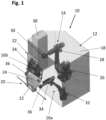
- the application arrangement 10 for applying a sealing profile to a circumferential sealing surface of a motor vehicle part 24, in this example a motor vehicle door.
- the application arrangement 10 comprises an application station 12 with an application robot 14 and two positioning robots 16a, 16b, which are arranged in a protective housing 18.
- the protective housing 18 is open in the direction of a conveyor 20, which conveys the motor vehicle doors 24 past the application station 12 by means of a transport holder 22, the motor vehicle door 24 entering the access area of the application robot 14 and the positioning robots 16a, 16b.
- the conveying device 20 is shown here in simplified form only by arrows and is known as such in its variable types of embodiment.
- the transport bracket 22, also called a hanger holds the motor vehicle door 24 securely during transport.
- the two positioning robots 16a, 16b are used to hold the motor vehicle door 24 firmly and immovably during the application of the sealing profile.
- the positioning robots 16a, 16b could also remove the motor vehicle door 24 from the transport holder 22 or remove it together with the transport holder 22 from the conveyor device 20 in order to move it into an application position.
- the motor vehicle door 24 is thus only stabilized in its application position by the positioning robots 16a, 16b, ie it is kept largely immobile. In terms of equipment, this can be implemented much more simply and cost-effectively than if the positioning robots 16a, 16b had to have a transport functionality.
- the application robot 14 preferably has a base 26 which can be pivoted about a horizontal axis and on which a two-part arm 28 is preferably pivotably held, the two parts of which can be pivoted relative to one another.
- a multi-movable application head 30 which, by appropriately controlling the application robot 14, is able to move along the sealing surface of the motor vehicle door 24 and thereby apply the sealing profile to it.
- each positioning robot 16a, 16b preferably contains a base 32 that can be rotated about a vertical axis and on which a two-part arm 34 is pivotably mounted, at the end of which a gripper 36 is arranged that is capable of Motor vehicle door 24 to hold the application of the sealing profile.
- the gripper 36 can preferably hold the edge of the motor vehicle door 24, which enables the motor vehicle door 24 to be reliably stabilized during application without impairing the access of the application robot 14 to the sealing surface.
- the application arrangement 10 has a controller 38, which controls the activity of the conveying device 20 in the area of the application station 12 as well as the application robot 14 and the two positioning robots 16a, 16b in order to ensure an exact, reproducible application of the sealing profile on the motor vehicle door 24.
- the movement of the transport holder 22 in the conveyor device 20 is stopped after it has reached its application position in the access area of the application robot 14 and the two positioning robots 16a, 16b and is set in motion again after application in order to receive the next transport holder 22 equipped with a motor vehicle door 24.
- the transport holders 22 can therefore preferably be individually moved and stopped in the conveyor device 20 by the controller 38 .
Landscapes
- Engineering & Computer Science (AREA)
- Mechanical Engineering (AREA)
- Robotics (AREA)
- Manufacturing & Machinery (AREA)
- Chemical & Material Sciences (AREA)
- Combustion & Propulsion (AREA)
- Transportation (AREA)
- Automobile Manufacture Line, Endless Track Vehicle, Trailer (AREA)
Priority Applications (3)
| Application Number | Priority Date | Filing Date | Title |
|---|---|---|---|
| EP21217434.6A EP4201581A1 (fr) | 2021-12-23 | 2021-12-23 | Dispositif d'application d'un profilé de joint d'étanchéité |
| PCT/EP2022/085093 WO2023117476A1 (fr) | 2021-12-23 | 2022-12-09 | Agencement d'application d'un profilé d'étanchéité |
| EP22835279.5A EP4221933B1 (fr) | 2021-12-23 | 2022-12-09 | Dispositif d'application d'un profilé de joint d'étanchéité |
Applications Claiming Priority (1)
| Application Number | Priority Date | Filing Date | Title |
|---|---|---|---|
| EP21217434.6A EP4201581A1 (fr) | 2021-12-23 | 2021-12-23 | Dispositif d'application d'un profilé de joint d'étanchéité |
Publications (1)
| Publication Number | Publication Date |
|---|---|
| EP4201581A1 true EP4201581A1 (fr) | 2023-06-28 |
Family
ID=80112441
Family Applications (2)
| Application Number | Title | Priority Date | Filing Date |
|---|---|---|---|
| EP21217434.6A Withdrawn EP4201581A1 (fr) | 2021-12-23 | 2021-12-23 | Dispositif d'application d'un profilé de joint d'étanchéité |
| EP22835279.5A Active EP4221933B1 (fr) | 2021-12-23 | 2022-12-09 | Dispositif d'application d'un profilé de joint d'étanchéité |
Family Applications After (1)
| Application Number | Title | Priority Date | Filing Date |
|---|---|---|---|
| EP22835279.5A Active EP4221933B1 (fr) | 2021-12-23 | 2022-12-09 | Dispositif d'application d'un profilé de joint d'étanchéité |
Country Status (2)
| Country | Link |
|---|---|
| EP (2) | EP4201581A1 (fr) |
| WO (1) | WO2023117476A1 (fr) |
Citations (7)
| Publication number | Priority date | Publication date | Assignee | Title |
|---|---|---|---|---|
| DE202006002159U1 (de) * | 2006-02-09 | 2007-04-26 | Kuka Schweissanlagen Gmbh | Applikationseinrichtung |
| DE602004000743T2 (de) * | 2003-07-30 | 2007-05-10 | Hutchinson | Vorrichtung zum fortlaufenden Legen eines Dichtungsprofils, insbesondere auf der Karosserie oder einem Karosserieteil eines Kraftfahrzeugs |
| WO2011134994A1 (fr) * | 2010-04-27 | 2011-11-03 | Kuka Laboratories Gmbh | Dispositif de traitement |
| DE102016116107A1 (de) * | 2016-08-30 | 2018-03-01 | Tesla Grohmann Automation Gmbh | Verfahren zum Anbringen von Dichtungsprofilen mit einer Klebeschicht an Fahrzeugkarosserien oder deren Teilen |
| DE102018108478A1 (de) | 2018-04-10 | 2019-10-10 | Aytec Automation Gmbh | Vorrichtung zum Aufbringen eines Dichtungsprofils |
| DE102019215566A1 (de) * | 2019-10-10 | 2021-04-15 | Thyssenkrupp Ag | Spannvorrichtung zum stationären Halten eines Bauteils |
| DE102005063564B3 (de) * | 2005-06-16 | 2021-07-15 | Cqlt Saargummi Technologies S.À.R.L. | Verwendung eines Rollenhalters |
-
2021
- 2021-12-23 EP EP21217434.6A patent/EP4201581A1/fr not_active Withdrawn
-
2022
- 2022-12-09 WO PCT/EP2022/085093 patent/WO2023117476A1/fr not_active Ceased
- 2022-12-09 EP EP22835279.5A patent/EP4221933B1/fr active Active
Patent Citations (7)
| Publication number | Priority date | Publication date | Assignee | Title |
|---|---|---|---|---|
| DE602004000743T2 (de) * | 2003-07-30 | 2007-05-10 | Hutchinson | Vorrichtung zum fortlaufenden Legen eines Dichtungsprofils, insbesondere auf der Karosserie oder einem Karosserieteil eines Kraftfahrzeugs |
| DE102005063564B3 (de) * | 2005-06-16 | 2021-07-15 | Cqlt Saargummi Technologies S.À.R.L. | Verwendung eines Rollenhalters |
| DE202006002159U1 (de) * | 2006-02-09 | 2007-04-26 | Kuka Schweissanlagen Gmbh | Applikationseinrichtung |
| WO2011134994A1 (fr) * | 2010-04-27 | 2011-11-03 | Kuka Laboratories Gmbh | Dispositif de traitement |
| DE102016116107A1 (de) * | 2016-08-30 | 2018-03-01 | Tesla Grohmann Automation Gmbh | Verfahren zum Anbringen von Dichtungsprofilen mit einer Klebeschicht an Fahrzeugkarosserien oder deren Teilen |
| DE102018108478A1 (de) | 2018-04-10 | 2019-10-10 | Aytec Automation Gmbh | Vorrichtung zum Aufbringen eines Dichtungsprofils |
| DE102019215566A1 (de) * | 2019-10-10 | 2021-04-15 | Thyssenkrupp Ag | Spannvorrichtung zum stationären Halten eines Bauteils |
Also Published As
| Publication number | Publication date |
|---|---|
| EP4221933A1 (fr) | 2023-08-09 |
| WO2023117476A1 (fr) | 2023-06-29 |
| EP4221933B1 (fr) | 2024-02-21 |
Similar Documents
| Publication | Publication Date | Title |
|---|---|---|
| DE3620536C2 (fr) | ||
| DE19940959B4 (de) | Kraftfahrzeug mit einer Karosserie | |
| DE102010062048A1 (de) | Greifer für Fahrzeugtür | |
| DE3211688A1 (de) | Roboter fuer fertigungs- und/oder montagezwecke | |
| DE8905574U1 (de) | Antriebseinrichtung für ein motorisch antreibbares Klappverdeck | |
| EP3762184B1 (fr) | Unité de pivotement destinée à un robot manipulateur et procédé associé | |
| EP3148826B1 (fr) | Dispositif pourvu d'un couvercle pour toit de véhicule | |
| DE60317995T2 (de) | Tür für automatisierte Maschine | |
| EP4201581A1 (fr) | Dispositif d'application d'un profilé de joint d'étanchéité | |
| EP2286927B1 (fr) | Installation de robot | |
| DE10251393B4 (de) | Verfahren und Vorrichtung zur Schließkeilsimulation | |
| DE202015004305U1 (de) | Vorrichtung zum Öffnen und Schließen ein oder mehrerer Bugklappen, insbesondere für Schienenfahrzeuge | |
| EP1673249B1 (fr) | Element de blocage de portiere | |
| DE102015203812B4 (de) | Feder- und/oder Dämpferelement | |
| DE20120958U1 (de) | Armlehne für ein Kraftfahrzeug | |
| DE102023108536B4 (de) | Luftleitvorrichtung einer Kraftfahrzeugkarosserie mit einem flexiblen Luftleitelement | |
| DE19515041C1 (de) | Einrichtung zum Wechseln von Gegenständen zwischen einer Werkzeugmaschine und einem Magazin | |
| DE2502189C3 (de) | Fernverstellbarer Rückblickspiegel für Kraftfahrzeuge, insbesondere Außenrückblickspiegel | |
| EP0436883A1 (fr) | Dispositif de serrage | |
| DE3231639C2 (fr) | ||
| DE1177305B (de) | Handbetaetigter Manipulator | |
| DE102019008307A1 (de) | Werkstück-Spannnvorrichtung | |
| DE102019128311A1 (de) | Bewegbares Karosserieelement für eine Kraftfahrzeugkarosserie | |
| DE102010062045A1 (de) | Vorrichtung und Verfahren für die Montage von Karosserieteilen an Fahrzeugkarosserien | |
| DE10217570A1 (de) | In Schnittrichtung beweglicher Besäumtisch und Holzbearbeitungsmaschine mit einem Besäumtisch |
Legal Events
| Date | Code | Title | Description |
|---|---|---|---|
| PUAI | Public reference made under article 153(3) epc to a published international application that has entered the european phase |
Free format text: ORIGINAL CODE: 0009012 |
|
| STAA | Information on the status of an ep patent application or granted ep patent |
Free format text: STATUS: THE APPLICATION HAS BEEN PUBLISHED |
|
| AK | Designated contracting states |
Kind code of ref document: A1 Designated state(s): AL AT BE BG CH CY CZ DE DK EE ES FI FR GB GR HR HU IE IS IT LI LT LU LV MC MK MT NL NO PL PT RO RS SE SI SK SM TR |
|
| STAA | Information on the status of an ep patent application or granted ep patent |
Free format text: STATUS: THE APPLICATION IS DEEMED TO BE WITHDRAWN |
|
| 18D | Application deemed to be withdrawn |
Effective date: 20240103 |