EP4201583A1 - Fraiseuse dentaire, adaptateur destiné à être utilisé dans une fraiseuse dentaire et procédé d'installation d'une fraiseuse dentaire - Google Patents
Fraiseuse dentaire, adaptateur destiné à être utilisé dans une fraiseuse dentaire et procédé d'installation d'une fraiseuse dentaire Download PDFInfo
- Publication number
- EP4201583A1 EP4201583A1 EP21217580.6A EP21217580A EP4201583A1 EP 4201583 A1 EP4201583 A1 EP 4201583A1 EP 21217580 A EP21217580 A EP 21217580A EP 4201583 A1 EP4201583 A1 EP 4201583A1
- Authority
- EP
- European Patent Office
- Prior art keywords
- adapter
- milling machine
- dental milling
- holder
- blank
- Prior art date
- Legal status (The legal status is an assumption and is not a legal conclusion. Google has not performed a legal analysis and makes no representation as to the accuracy of the status listed.)
- Granted
Links
Images




Classifications
-
- B—PERFORMING OPERATIONS; TRANSPORTING
- B23—MACHINE TOOLS; METAL-WORKING NOT OTHERWISE PROVIDED FOR
- B23C—MILLING
- B23C3/00—Milling particular work; Special milling operations; Machines therefor
- B23C3/28—Grooving workpieces
- B23C3/34—Milling grooves of other forms, e.g. circumferential
-
- A—HUMAN NECESSITIES
- A61—MEDICAL OR VETERINARY SCIENCE; HYGIENE
- A61C—DENTISTRY; APPARATUS OR METHODS FOR ORAL OR DENTAL HYGIENE
- A61C13/00—Dental prostheses; Making same
- A61C13/0003—Making bridge-work, inlays, implants or the like
- A61C13/0022—Blanks or green, unfinished dental restoration parts
-
- A—HUMAN NECESSITIES
- A61—MEDICAL OR VETERINARY SCIENCE; HYGIENE
- A61C—DENTISTRY; APPARATUS OR METHODS FOR ORAL OR DENTAL HYGIENE
- A61C13/00—Dental prostheses; Making same
- A61C13/12—Tools for fastening artificial teeth; Holders, clamps, or stands for artificial teeth
-
- B—PERFORMING OPERATIONS; TRANSPORTING
- B23—MACHINE TOOLS; METAL-WORKING NOT OTHERWISE PROVIDED FOR
- B23C—MILLING
- B23C9/00—Details or accessories so far as specially adapted to milling machines or cutter
-
- B—PERFORMING OPERATIONS; TRANSPORTING
- B23—MACHINE TOOLS; METAL-WORKING NOT OTHERWISE PROVIDED FOR
- B23Q—DETAILS, COMPONENTS, OR ACCESSORIES FOR MACHINE TOOLS, e.g. ARRANGEMENTS FOR COPYING OR CONTROLLING; MACHINE TOOLS IN GENERAL CHARACTERISED BY THE CONSTRUCTION OF PARTICULAR DETAILS OR COMPONENTS; COMBINATIONS OR ASSOCIATIONS OF METAL-WORKING MACHINES, NOT DIRECTED TO A PARTICULAR RESULT
- B23Q7/00—Arrangements for handling work specially combined with or arranged in, or specially adapted for use in connection with, machine tools, e.g. for conveying, loading, positioning, discharging, sorting
- B23Q7/14—Arrangements for handling work specially combined with or arranged in, or specially adapted for use in connection with, machine tools, e.g. for conveying, loading, positioning, discharging, sorting co-ordinated in production lines
- B23Q7/1426—Arrangements for handling work specially combined with or arranged in, or specially adapted for use in connection with, machine tools, e.g. for conveying, loading, positioning, discharging, sorting co-ordinated in production lines with work holders not rigidly fixed to the transport devices
-
- B—PERFORMING OPERATIONS; TRANSPORTING
- B23—MACHINE TOOLS; METAL-WORKING NOT OTHERWISE PROVIDED FOR
- B23C—MILLING
- B23C2220/00—Details of milling processes
- B23C2220/36—Production of grooves
-
- B—PERFORMING OPERATIONS; TRANSPORTING
- B23—MACHINE TOOLS; METAL-WORKING NOT OTHERWISE PROVIDED FOR
- B23Q—DETAILS, COMPONENTS, OR ACCESSORIES FOR MACHINE TOOLS, e.g. ARRANGEMENTS FOR COPYING OR CONTROLLING; MACHINE TOOLS IN GENERAL CHARACTERISED BY THE CONSTRUCTION OF PARTICULAR DETAILS OR COMPONENTS; COMBINATIONS OR ASSOCIATIONS OF METAL-WORKING MACHINES, NOT DIRECTED TO A PARTICULAR RESULT
- B23Q1/00—Members which are comprised in the general build-up of a form of machine, particularly relatively large fixed members
- B23Q1/25—Movable or adjustable work or tool supports
- B23Q1/44—Movable or adjustable work or tool supports using particular mechanisms
- B23Q1/50—Movable or adjustable work or tool supports using particular mechanisms with rotating pairs only, the rotating pairs being the first two elements of the mechanism
- B23Q1/52—Movable or adjustable work or tool supports using particular mechanisms with rotating pairs only, the rotating pairs being the first two elements of the mechanism a single rotating pair
- B23Q1/525—Movable or adjustable work or tool supports using particular mechanisms with rotating pairs only, the rotating pairs being the first two elements of the mechanism a single rotating pair which is parallel to the working surface
-
- Y—GENERAL TAGGING OF NEW TECHNOLOGICAL DEVELOPMENTS; GENERAL TAGGING OF CROSS-SECTIONAL TECHNOLOGIES SPANNING OVER SEVERAL SECTIONS OF THE IPC; TECHNICAL SUBJECTS COVERED BY FORMER USPC CROSS-REFERENCE ART COLLECTIONS [XRACs] AND DIGESTS
- Y10—TECHNICAL SUBJECTS COVERED BY FORMER USPC
- Y10T—TECHNICAL SUBJECTS COVERED BY FORMER US CLASSIFICATION
- Y10T409/00—Gear cutting, milling, or planing
- Y10T409/30—Milling
- Y10T409/303752—Process
-
- Y—GENERAL TAGGING OF NEW TECHNOLOGICAL DEVELOPMENTS; GENERAL TAGGING OF CROSS-SECTIONAL TECHNOLOGIES SPANNING OVER SEVERAL SECTIONS OF THE IPC; TECHNICAL SUBJECTS COVERED BY FORMER USPC CROSS-REFERENCE ART COLLECTIONS [XRACs] AND DIGESTS
- Y10—TECHNICAL SUBJECTS COVERED BY FORMER USPC
- Y10T—TECHNICAL SUBJECTS COVERED BY FORMER US CLASSIFICATION
- Y10T409/00—Gear cutting, milling, or planing
- Y10T409/30—Milling
- Y10T409/304536—Milling including means to infeed work to cutter
- Y10T409/305544—Milling including means to infeed work to cutter with work holder
- Y10T409/305656—Milling including means to infeed work to cutter with work holder including means to support work for rotation during operation
- Y10T409/305824—Milling including means to infeed work to cutter with work holder including means to support work for rotation during operation with angular movement of work
-
- Y—GENERAL TAGGING OF NEW TECHNOLOGICAL DEVELOPMENTS; GENERAL TAGGING OF CROSS-SECTIONAL TECHNOLOGIES SPANNING OVER SEVERAL SECTIONS OF THE IPC; TECHNICAL SUBJECTS COVERED BY FORMER USPC CROSS-REFERENCE ART COLLECTIONS [XRACs] AND DIGESTS
- Y10—TECHNICAL SUBJECTS COVERED BY FORMER USPC
- Y10T—TECHNICAL SUBJECTS COVERED BY FORMER US CLASSIFICATION
- Y10T409/00—Gear cutting, milling, or planing
- Y10T409/30—Milling
- Y10T409/30868—Work support
- Y10T409/309016—Work support with work holder or guide
Definitions
- the invention relates to a dental milling machine according to the preamble of claim 1 and an adapter for use in such a dental milling machine.
- the invention relates to a method for setting up a dental milling machine.
- blanks - hereinafter referred to as blanks - machined from different materials.
- blanks of this type are standardized in terms of their dimensions, so that they can be used across different systems in various dental milling machines.
- Manufacturers are now starting to sell dental milling machines that can only accommodate blanks with dimensions that deviate from the norm. Users are therefore dependent on using the blanks associated with the dental milling machine. Flexible use of the dental milling machine is not possible.
- Dental milling machines for the calibration of which a test workpiece with several reference points is clamped in the workpiece holder.
- the reference points are approached by a probe clamped in the tool holder.
- the coordinates recorded at the reference points are stored in the control of the dental milling machine.
- the virtual coordinate system of the workpiece holder and thus also of the workpiece is adjusted on the basis of these reference points.
- a reference workpiece is milled, the target geometry of which is stored in the controller of the dental milling machine.
- the geometry of the reference workpiece is measured and compared with the target geometry.
- the virtual coordinate system can be corrected on the basis of the deviation between the actual geometry and the target geometry of the reference workpiece. This step can be repeated until the reference workpiece is manufactured with sufficient accuracy.
- Such a calibration of the dental milling machine is extremely time-consuming and expensive. Due to the complexity of a calibration, it usually has to be carried out by service technicians.
- the invention is based on the object of further developing a dental milling machine in such a way that the dental milling machine can be set up in a simple manner and at the same time can be used flexibly.
- the task with regard to the dental milling machine is solved by a dental milling machine according to the features of claim 1 .
- the invention is based on the further object of specifying a means that enables simple setup and at the same time flexible use of a dental milling machine.
- the invention is based on the additional object of specifying a method that enables simple setup and at the same time flexible use of a dental milling machine.
- the dental milling machine includes a workpiece holder.
- the workpiece holder has a holder and an adapter.
- the adapter is attached to the bracket.
- the adapter has at least one first seat for attachment to the holder of the dental milling machine. In a first state, the adapter is a blank and is designed to be milled over by the dental milling machine.
- the adapter is milled over and given the contour intended for holding a blank.
- the operator can, for example, plan the corresponding milling operation depending on the blanks to be processed, whereby the desired contour is achieved on the adapter. Accordingly, any desired contour adapted to the operator's wishes can be provided on the adapter, which is adapted to the blanks used by the operator. Consequently, the dental milling machine is not limited to the processing of specific blanks, but can be used for a wide range of blanks.
- a further advantage of the dental milling machine according to the invention is that the milling over of the adapter eliminates the need for an additional calibration of the dental milling machine.
- the contour for holding the workpiece is milled into the adapter, which determines the position of the workpiece holder in the dental milling machine.
- the exact position of the workpiece holder is known to the control of the dental milling machine, since this corresponds to the position of the contour programmed for the milling process.
- the adapter is milled over, the inaccuracies of the dental milling machine are transferred to the adapter, whereby the zero points of the workpiece holder and the dental milling machine are coordinated relative to one another.
- the adapter is preferably milled over by the dental milling machine and includes a contour for receiving a blank. Accordingly, in the second state of the adapter, a workpiece can be accommodated in the workpiece holder.
- the adapter is preferably made of plastic, in particular made of injection molding.
- plastic the adapter has sufficient strength to be able to hold workpieces in it during milling. At the same time, plastic is much easier to mill than alternative materials that would be suitable for such an adapter, such as aluminum or other metallic materials.
- the bracket is preferably formed from aluminum.
- the adapter is detachably held on the holder.
- An adapter with an individual contour for accommodating this blank can be provided for each blank accommodating contour. If several blanks are to be machined in the dental milling machine, the mounting contours of which are different, the adapter can then be easily changed and the corresponding blank machined.
- the workpiece holder comprises at least one clamping device.
- the clamping means is preferably held on the adapter. If the blank is clamped in the workpiece holder, the blank rests on the adapter and is clamped against the adapter by the clamping device.
- the adapter is preferably arcuate in its first state.
- the commercially available blanks are circular and disk-shaped.
- the adapter In its second state, the adapter has an at least partially inverse contour to the blank on, preferably also arcuate, in particular semicircular.
- the contour of the adapter in its first state approximates the contour in the second state.
- the holder and the adapter are advantageously aligned with one another via a dowel pin.
- the method according to the invention for setting up a dental milling machine provides a dental milling machine, the dental milling machine having a workpiece holder, the workpiece holder comprising a holder and an adapter, the adapter being fastened to the holder.
- the adapter is a blank and is milled over by the dental milling machine in such a way that a receiving contour for receiving a blank is formed on the adapter.
- At least one clamping means is preferably attached to the adapter.
- the clamping means is fastened on the adapter, in particular after the adapter has been milled over. When machining a blank, the blank is held between the adapter and the at least one clamping device.
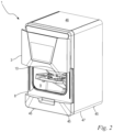
- a dental milling machine 1 is shown.
- the dental milling machine 1 is provided for the production of a dental prosthesis, in particular for the production of crowns and bridges. Such a denture is made from a blank—referred to as blank 15 below.
- the dental milling machine 1 has a housing 2 with a loading flap 3 .
- the housing 2 delimits an interior space 9 of the dental milling machine 1. After the loading flap 3 has been opened, access to the interior space 9 of the dental milling machine 1 is open, so that a blank 15 can be inserted or removed, for example.
- the housing 2 of the dental milling machine has a top 46 and a bottom 47 .
- a plurality of feet 45 are arranged on the underside 47 of the dental milling machine 1 , with the dental milling machine 1 being placed on its feet 45 .
- the term “top” indicates a direction running from the bottom 47 to the top 46 of the dental milling machine 1 .
- the term “bottom” refers to a direction running from the top 46 to the bottom 47 of the dental milling machine 1 .
- a milling spindle 5 is arranged in the dental milling machine 1 .
- the milling spindle 5 comprises an electric motor 49 and a spindle 48 driven by the electric motor 49.
- the milling spindle 5 can be translated in space via a drive system (not shown in detail), i.e. in the direction of the x, y and z axes of the dental milling machine 1.
- the milling spindle 5 is preferably rotationally adjustable and can be pivoted about the degrees of freedom A and B, ie about the x-axis or about the y-axis.
- the degrees of freedom of the milling spindle are in 1 indicated schematically.
- the dental milling machine 1 comprises an in 1 control device 4 shown only schematically.
- the control device 4 is used for the electrical supply and control of the milling spindle 5 and the drive system.
- the milling spindle 5 and the drive system are connected to the control device 4 in particular via an electrical connection.
- FIG 2 the dental milling machine 1 is shown with the loading flap 3 open.
- the opened loading flap 3 releases a shop opening 8 .
- Blanks 15 can be guided through the loading opening 8 into the interior 9 of the dental milling machine 1 and inserted into a workpiece holder 10 of the dental milling machine 1 .
- the workpiece holder 10 is arranged in the interior 9 of the dental milling machine 1 .
- the workpiece holder 10 serves to hold a blank 15 and to fix it in such a way that an unintentional displacement of the blank 15 can be avoided during the machining of the blank 15 . This enables precise machining of the blank 15 by machining.
- the workpiece holder 10 is held on a carrier 20 of the dental milling machine 1 .
- the workpiece holder 10 is held on the carrier 20 such that it can pivot about a pivot axis 21 .
- the workpiece holder 10 extends from its first end 22 to its second end 23.
- the workpiece holder 10 is pivotably mounted on the carrier 20 at its two ends 22, 23.
- the workpiece holder 10 is operatively connected to an electric motor, not shown, in particular a stepper motor, the electric motor causing a pivoting movement 24 of the workpiece holder 10 about the pivot axis 21 .
- the workpiece holder 10 comprises a holder 11 and an adapter 12.
- the adapter 12 is arranged on the holder 11.
- the workpiece holder 10 comprises at least one clamping device 13.
- the clamping means 13 are designed to clamp the blank 15 against the adapter 12 .
- the blank 15 is preferably held directly between the adapter 12 and the clamping means 13 .
- It can also be provided to provide only one clamping means 13, but also more than two clamping means 13.
- the clamping means 13 are preferably attached to the adapter 12 .
- the clamping means 13 can also be attached to the holder 11 .
- a screw connection 14 is provided for fixing of each clamping means 13 .
- the clamping means 13 can be fastened, for example, via a quick-action clamp, an eccentric lever or the like.
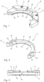
- the adapter 12 is shown.
- the adapter 12 is designed as a blank 16 and is therefore in a first state 17.
- the adapter 12 has not yet been milled over by the dental milling machine 1.
- the adapter 12 is preferably made of a plastic. It can be expedient to form the adapter as an injection molding. The cutting forces that occur when milling plastic are significantly lower than those of a metal material.
- the adapter 12 extends from its first end face 62 to its second end face 63.
- the adapter 12 is arcuate, with the concave side of the adapter 12 being an inside 65 and the convex side of the adapter 12 being an outside 64 Furthermore, the adapter 12 comprises an upper side 60 and an underside 61 which are connected to one another via the end faces 62, 63, the inner side 65 and the outer side 64.
- the blank 16 is designed as a semi-finished product and includes a number of prefabricated openings 26, 27, 29 and functional contours 30, 31.
- the adapter 12 thus includes at least one opening 27, via which the adapter 12 is connected to the holder on its underside 61 11 can be screwed.
- the underside 61 thus forms a receptacle 66 for connection to the holder 11.
- An internal thread is provided in the opening 27.
- the internal thread is a threaded sleeve cast into the blank 16 .
- three such openings 27 are provided for connection to the mount 11 .
- a different number of openings 27 can also be useful.
- the adapter 12 includes two further openings 26, each with a thread, via which the clamping means 13 can be fastened on the upper side 60 of the adapter 12.
- 12 positioning elements 31 are provided on the top 60 of the adapter, on which the clamping means 13 rests in the assembled state of the workpiece holder 10 . Furthermore, on the upper side 60 of the adapter 13 a central web 30 is formed, at each end of which a clamping means 13 comes to rest. When fastening a clamping device 13 to the adapter 12, it is placed on the positioning elements 31 and at least partially encompasses one end of the central web 30 via a guide contour 33 of the clamping device 13. The clamping element 13 is positioned in contact with the central web 30 in such a way that it can be screwed to the adapter 12. This allows the workpiece holder 10 to be assembled easily.
- the holder 11 of the workpiece holder 10 is shown.
- the holder 11 has a bearing surface 40 which is used to rest the underside 61 of the adapter 12 .
- the holder 11 extends in an arc from a first end 51 to a second end 52.
- a support wall 41 is provided on the bearing surface 40.
- FIG. The support wall 41 is divided into three sections 55, 56, 57.
- the first section 55 of the support wall 41 is formed at the first end 51 of the bracket 11.
- the third section 57 of the support wall 41 is formed at the second end 52 of the bracket 11 .
- the first section 55 and the third section 57 are connected to one another via the arcuate second section 56 .
- the first section 55 and the second section of the support wall 41 are aligned substantially parallel to one another.
- the support wall 41 is preferably aligned perpendicularly to the bearing surface 41 .
- the holder 11 is preferably formed from a metal material, in particular from an aluminum alloy.
- two stops 42 are provided on the first section 55 of the support wall 41 .
- the stops 42 are designed as projections of the support wall 41 . It can also be expedient to provide the two stops 42 alternatively on the third section 57 of the support wall 41 .
- the two stops 42 form a limitation of the adapter 12 with regard to the x degree of freedom.
- the second section 56 of the support wall 41 forms a limitation of the y degree of freedom for the adapter 12 .
- the bearing surface 40 represents the limitation of the z degree of freedom. The alignment of the adapter 12 with respect to the holder 11 is thus determined in all spatial directions.
- the adapter 12 To fasten the adapter 12 on the holder 11, the adapter must be placed with its underside 61 on the bearing surface 40 of the holder 11.
- the adapter 12 is to be pushed against the stops 42 of the first section 55 of the support wall 41 and the second section 56 of the support wall 41 itself.
- a dowel pin is preferably provided for additional securing of the position between the holder 11 and the adapter 12 , which engages in the opening 44 in the holder 11 and in the opening 29 in the adapter 12 .
- 11 through holes 43 are provided on the bracket.
- the adapter 12 is detachably attached to the mount 12 .
- the fastening method ensures sufficient accuracy in the alignment of the adapter 12 and the holder 11, so that the workpiece holder 10 does not have to be set up again, i.e. the adjustment of the x and y coordinates of the workpiece holder 10 in the control device 4 .
- changing different adapters 12 is also possible.
- the arcuate design of the holder 11 and the adapter 12 allow the blank 15 to be machined on its peripheral side.
- the blank 15 is accommodated in the arcuate workpiece holder 10, as a result of which the milling tool can machine on the peripheral side of the blank 15 without colliding with the workpiece holder 10 in the process.
- the arcuate configuration of the workpiece holder 10 and the Pivotability of the workpiece holder 10 increases the effective working space of the dental milling machine 1.
- the workpiece holder 10 is connected to the carrier 20 via two shafts 53 . At least one of the two shafts 53 is driven by the electric motor to pivot the workpiece holder 10 .
- a recess is provided both at the first end 51 and at the second end 52 of the bracket 11, which form a hub 50 for connection to the shafts 53 of the carrier 20.
- the hubs 50 are screwed to a supporting element 54 of the carrier 20 .
- the holder 11 is preferably connected to the shafts 53 in a form-fitting manner in the pivoting direction 24, for example via a tongue and groove connection or a cylindrical pin.
- the adapter 12 As in the Figures 4 and 5 shown, are in the first state 17 of the adapter 12 all openings and contours of the adapter 12, which are used to align and attach the holder 11 and the clamping means 13, already prefabricated. Only one contour 35 for receiving a blank 15 ( 6 ) is not formed in the first state 17 of the adapter 12.
- This is to be manufactured as follows in the dental milling machine 1:
- the adapter 12 is to be attached to the bracket 11 as described above.
- a large number of different manufacturing programs for completing the adapter 12 are preferably stored in the control device 4 .
- the operator has to select a production program which is aimed at the corresponding blank 16 and provides the receiving contour 35 desired by the operator.
- the production program is to be started by the operator, as a result of which the dental milling machine 1 performs the milling on the blank 16 .
- a receiving contour 35 is now milled on the adapter 12 .
- the receiving contour 35 is milled into the inside 65 of the adapter 12 .
- the adapter 12 includes a receiving contour 35 and is thus in its second state 18, as in 6 shown.
- the receiving contour 35 is formed on the inside 65 of the adapter.
- Receiving contour 35 is formed from a base wall 37 and a projection 38 formed on base wall 37 . Both the base wall 37 and the projection 38 are formed on the inside 65 of the adapter 12 .
- the base wall 37 extends in the direction from the bottom 61 to the top 60 of the adapter 12.
- the projection 38 is adjacent to the bottom 61 of the adapter 12 at.
- the base wall 37 runs from the adapter 12 to the upper side 60 of the adapter 12.
- the receiving contour 35 is arcuate, in particular semicircular.
- the projection 38 extends along the entire base wall 37 of the adapter 12, ie from the first end face 62 to the second end face 63 extend over sections along the base wall 37 of the adapter 12.
- the receiving contour 35 can be adapted almost arbitrarily to the wishes of the operator or to the counter-contour of the blank 15 to be picked up.
- the corresponding production program stored in the control device 4 is to be selected.
- a production program can also be created by the operator.
- the clamping means 13 are to be screwed onto the upper side 60 of the milled-over adapter 12 .
- the clamping means 13 comprises a clamping contour 39.
- the clamping means 13 is arranged on the adapter 12 in such a way that the clamping contour 39 protrudes over the base wall 37 of the adapter 12.
- screw connections 14 To fasten the blank 15, it is preferably clamped in contact with the base wall 37 between the projection 38 of the adapter 12 and the clamping contour 39 of the clamping means 13 ( Figures 10 and 11 ).
- screw connections 14 must be tightened.
- Milling over the adapter 12 eliminates the need for an additional calibration of the dental milling machine 1 .
- the receiving contour 35 for receiving the blank is milled into the adapter 12 , as a result of which the position of the workpiece holder 10 in the dental milling machine 1 is fixed.
- the control device 4 of the dental milling machine 1 is therefore aware of the exact position of the workpiece holder 10, since this corresponds to the position of the contour programmed for the milling.
- an alternative blank 16' is shown.
- the blank 16 ' differs from the blank 16 after the Figures 4 and 5 in that the inside 65 'is not arcuate like the outside 64 formed. Rather, the inner side 65' is flat.
- the first end face 62 thus merges directly into the inner side 65 ′, which then in turn runs into the second end face 63 .
- the advantage of this embodiment of the blank 16 ′ is that any receiving contours 35 can be milled into the blank 16 .
- Such receiving contours are not limited to circular shapes, but can also be in the form of polygons or free-form contours. The gain in flexibility with regard to the formation of the mounting contours is of course accompanied by higher chip removal.
- a machined form of the alternative blank 16' may be an adapter 12' having three discrete projections 38 on the base wall 37.
- the projections 38 are not connected to each other.
- the projections 38 form a three-point support, which ensures that a blank 15 or a comparable workpiece is securely fastened.
- other geometries for the adapter 12 can also be expedient.
Landscapes
- Health & Medical Sciences (AREA)
- Mechanical Engineering (AREA)
- Engineering & Computer Science (AREA)
- Epidemiology (AREA)
- Life Sciences & Earth Sciences (AREA)
- Animal Behavior & Ethology (AREA)
- General Health & Medical Sciences (AREA)
- Public Health (AREA)
- Veterinary Medicine (AREA)
- Dentistry (AREA)
- Oral & Maxillofacial Surgery (AREA)
- Dental Tools And Instruments Or Auxiliary Dental Instruments (AREA)
- Jigs For Machine Tools (AREA)
Priority Applications (2)
| Application Number | Priority Date | Filing Date | Title |
|---|---|---|---|
| EP21217580.6A EP4201583B1 (fr) | 2021-12-23 | 2021-12-23 | Procédé d'installation d'un porte-pièce |
| US18/069,353 US20230201933A1 (en) | 2021-12-23 | 2022-12-21 | Dental milling machine, adapter for use in a dental milling machine, and method for setting up a dental milling machine |
Applications Claiming Priority (1)
| Application Number | Priority Date | Filing Date | Title |
|---|---|---|---|
| EP21217580.6A EP4201583B1 (fr) | 2021-12-23 | 2021-12-23 | Procédé d'installation d'un porte-pièce |
Publications (2)
| Publication Number | Publication Date |
|---|---|
| EP4201583A1 true EP4201583A1 (fr) | 2023-06-28 |
| EP4201583B1 EP4201583B1 (fr) | 2026-02-04 |
Family
ID=79021831
Family Applications (1)
| Application Number | Title | Priority Date | Filing Date |
|---|---|---|---|
| EP21217580.6A Active EP4201583B1 (fr) | 2021-12-23 | 2021-12-23 | Procédé d'installation d'un porte-pièce |
Country Status (2)
| Country | Link |
|---|---|
| US (1) | US20230201933A1 (fr) |
| EP (1) | EP4201583B1 (fr) |
Citations (2)
| Publication number | Priority date | Publication date | Assignee | Title |
|---|---|---|---|---|
| DE202013103515U1 (de) * | 2013-08-05 | 2013-09-12 | Ivoclar Vivadent Ag | Rohlingaufnahme sowie Dental-Fräsmaschine |
| US20140147225A1 (en) * | 2012-11-29 | 2014-05-29 | Jensen Industries Incorporated | Adapter for dental milling blank |
Family Cites Families (4)
| Publication number | Priority date | Publication date | Assignee | Title |
|---|---|---|---|---|
| DE59005464D1 (de) * | 1990-05-09 | 1994-05-26 | Siemens Ag | Rohlingkörper zur Herstellung eines Zahnrestaurations-Passkörpers. |
| EP2225090B1 (fr) * | 2007-11-29 | 2018-10-03 | 3M Innovative Properties Company | Fabrication tridimensionnelle |
| US8641938B2 (en) * | 2011-09-27 | 2014-02-04 | Cmp Industries Llc | Denture and method and apparatus of making same |
| ES2588707T3 (es) * | 2012-12-17 | 2016-11-04 | Ivoclar Vivadent Ag | Procedimiento y sistema para la construcción de una prótesis dental |
-
2021
- 2021-12-23 EP EP21217580.6A patent/EP4201583B1/fr active Active
-
2022
- 2022-12-21 US US18/069,353 patent/US20230201933A1/en active Pending
Patent Citations (2)
| Publication number | Priority date | Publication date | Assignee | Title |
|---|---|---|---|---|
| US20140147225A1 (en) * | 2012-11-29 | 2014-05-29 | Jensen Industries Incorporated | Adapter for dental milling blank |
| DE202013103515U1 (de) * | 2013-08-05 | 2013-09-12 | Ivoclar Vivadent Ag | Rohlingaufnahme sowie Dental-Fräsmaschine |
Also Published As
| Publication number | Publication date |
|---|---|
| US20230201933A1 (en) | 2023-06-29 |
| EP4201583B1 (fr) | 2026-02-04 |
Similar Documents
| Publication | Publication Date | Title |
|---|---|---|
| DE3729162C2 (fr) | ||
| EP2247405B1 (fr) | Dispositif de fixation pour une machine d'usinage par enlèvement de copeaux pilotée par ordinateur | |
| DE69113502T2 (de) | Verfahren zur Herstellung von Turbinenschaufeln. | |
| DE69216570T2 (de) | Maschine und Methode für Verfahren zum Feinschneiden | |
| CH696876A5 (de) | Verfahren und Vorrichtung zur Rundum-Bearbeitung eines Rohlings. | |
| EP4027936B1 (fr) | Dispositif de retenue d'une pièce dentaire | |
| EP1620219A1 (fr) | Outil de forage | |
| DE19708762B4 (de) | Verfahren zum Konfigurieren einer Vorrichtung für die Positionierung von Bauteilen auf einer Maschine | |
| EP0344178B1 (fr) | Dispositif d'enroulement pour machine d'enroulement a ressort avec elements pre-reglables remplacables | |
| EP0504691A2 (fr) | Poste de mesure et travail pour de grandes pièces | |
| EP0316552A2 (fr) | Dispositif pour usiner des trous à boulons ou à soupapes dans un disque ou une jante de roue d'un véhicule | |
| DE102012025399A1 (de) | Ausrichtvorrichtung, Ausrichtelement für eine solche Ausrichtvorrichtung und Ausrichtverfahren | |
| EP4201583B1 (fr) | Procédé d'installation d'un porte-pièce | |
| EP3781919A1 (fr) | Procédé de détermination de la masse et du centre de gravité d'une charge utile d'un système de déplacement, en particulier dans une machine-outil | |
| DE102008046086B4 (de) | Schleifmaschine | |
| WO2005005093A2 (fr) | Procede et dispositif d'usinage circulaire d'une ebauche | |
| EP0305955A2 (fr) | Méthode et système de mesure pour mesurer automatiquement le résultat de travail obtenu par un outil de coupe agissant sur une pièce lors d'une opération d'usinage | |
| DE3708363A1 (de) | Spannfutter fuer werkzeugmaschinen | |
| WO2016120477A1 (fr) | Machine-outil et procédé, en particulier de fabrication flexible plus efficace de modèles d'usinage au moyen de plusieurs axes | |
| DE69003501T2 (de) | Fräskopf, insbesondere für Bearbeitungsroboter. | |
| DE4207353A1 (de) | Werkzeughalter fuer ein schneidwerkzeug | |
| DE19940686A1 (de) | Verfahren und Vorrichtung zum CNC-gesteuerten Abrichten einer Regelscheibe einer Schleifmaschine für einen spitzenlosen Schleifprozess an einem Werkstück, Verfahren zum spitzenlosen Schleifen sowie Schleifmaschine | |
| DE102022212346A1 (de) | Schleifvorrichtung | |
| DE102008045516B3 (de) | Haltekopf zum Halten einer Bearbeitungseinheit und Maschine zum spanabhebenden Bearbeiten eines metallischen Werkstücks | |
| DE3939505A1 (de) | Verfahren und vorrichtung fuer die aufspannung eines werkstuecks auf einer werkzeugmaschine |
Legal Events
| Date | Code | Title | Description |
|---|---|---|---|
| PUAI | Public reference made under article 153(3) epc to a published international application that has entered the european phase |
Free format text: ORIGINAL CODE: 0009012 |
|
| STAA | Information on the status of an ep patent application or granted ep patent |
Free format text: STATUS: THE APPLICATION HAS BEEN PUBLISHED |
|
| AK | Designated contracting states |
Kind code of ref document: A1 Designated state(s): AL AT BE BG CH CY CZ DE DK EE ES FI FR GB GR HR HU IE IS IT LI LT LU LV MC MK MT NL NO PL PT RO RS SE SI SK SM TR |
|
| STAA | Information on the status of an ep patent application or granted ep patent |
Free format text: STATUS: REQUEST FOR EXAMINATION WAS MADE |
|
| 17P | Request for examination filed |
Effective date: 20231220 |
|
| RBV | Designated contracting states (corrected) |
Designated state(s): AL AT BE BG CH CY CZ DE DK EE ES FI FR GB GR HR HU IE IS IT LI LT LU LV MC MK MT NL NO PL PT RO RS SE SI SK SM TR |
|
| STAA | Information on the status of an ep patent application or granted ep patent |
Free format text: STATUS: EXAMINATION IS IN PROGRESS |
|
| 17Q | First examination report despatched |
Effective date: 20240304 |
|
| GRAP | Despatch of communication of intention to grant a patent |
Free format text: ORIGINAL CODE: EPIDOSNIGR1 |
|
| STAA | Information on the status of an ep patent application or granted ep patent |
Free format text: STATUS: GRANT OF PATENT IS INTENDED |
|
| INTG | Intention to grant announced |
Effective date: 20250827 |
|
| RAP3 | Party data changed (applicant data changed or rights of an application transferred) |
Owner name: VHF CAMFACTURE AKTIENGESELLSCHAFT |
|
| GRAS | Grant fee paid |
Free format text: ORIGINAL CODE: EPIDOSNIGR3 |
|
| GRAA | (expected) grant |
Free format text: ORIGINAL CODE: 0009210 |
|
| STAA | Information on the status of an ep patent application or granted ep patent |
Free format text: STATUS: THE PATENT HAS BEEN GRANTED |
|
| AK | Designated contracting states |
Kind code of ref document: B1 Designated state(s): AL AT BE BG CH CY CZ DE DK EE ES FI FR GB GR HR HU IE IS IT LI LT LU LV MC MK MT NL NO PL PT RO RS SE SI SK SM TR |
|
| REG | Reference to a national code |
Ref country code: CH Ref legal event code: F10 Free format text: ST27 STATUS EVENT CODE: U-0-0-F10-F00 (AS PROVIDED BY THE NATIONAL OFFICE) Effective date: 20260204 Ref country code: GB Ref legal event code: FG4D Free format text: NOT ENGLISH |
|
| REG | Reference to a national code |
Ref country code: DE Ref legal event code: R096 Ref document number: 502021009772 Country of ref document: DE |
|
| REG | Reference to a national code |
Ref country code: IE Ref legal event code: FG4D Free format text: LANGUAGE OF EP DOCUMENT: GERMAN |