EP4201722B1 - Control device of hybrid vehicle - Google Patents
Control device of hybrid vehicle Download PDFInfo
- Publication number
- EP4201722B1 EP4201722B1 EP22207292.8A EP22207292A EP4201722B1 EP 4201722 B1 EP4201722 B1 EP 4201722B1 EP 22207292 A EP22207292 A EP 22207292A EP 4201722 B1 EP4201722 B1 EP 4201722B1
- Authority
- EP
- European Patent Office
- Prior art keywords
- engine
- catalyst
- warm
- period
- temperature
- Prior art date
- Legal status (The legal status is an assumption and is not a legal conclusion. Google has not performed a legal analysis and makes no representation as to the accuracy of the status listed.)
- Active
Links
Images


Classifications
-
- B—PERFORMING OPERATIONS; TRANSPORTING
- B60—VEHICLES IN GENERAL
- B60K—ARRANGEMENT OR MOUNTING OF PROPULSION UNITS OR OF TRANSMISSIONS IN VEHICLES; ARRANGEMENT OR MOUNTING OF PLURAL DIVERSE PRIME-MOVERS IN VEHICLES; AUXILIARY DRIVES FOR VEHICLES; INSTRUMENTATION OR DASHBOARDS FOR VEHICLES; ARRANGEMENTS IN CONNECTION WITH COOLING, AIR INTAKE, GAS EXHAUST OR FUEL SUPPLY OF PROPULSION UNITS IN VEHICLES
- B60K6/00—Arrangement or mounting of plural diverse prime-movers for mutual or common propulsion, e.g. hybrid propulsion systems comprising electric motors and internal combustion engines
- B60K6/20—Arrangement or mounting of plural diverse prime-movers for mutual or common propulsion, e.g. hybrid propulsion systems comprising electric motors and internal combustion engines the prime-movers consisting of electric motors and internal combustion engines, e.g. HEVs
- B60K6/22—Arrangement or mounting of plural diverse prime-movers for mutual or common propulsion, e.g. hybrid propulsion systems comprising electric motors and internal combustion engines the prime-movers consisting of electric motors and internal combustion engines, e.g. HEVs characterised by apparatus, components or means specially adapted for HEVs
- B60K6/38—Arrangement or mounting of plural diverse prime-movers for mutual or common propulsion, e.g. hybrid propulsion systems comprising electric motors and internal combustion engines the prime-movers consisting of electric motors and internal combustion engines, e.g. HEVs characterised by apparatus, components or means specially adapted for HEVs characterised by the driveline clutches
- B60K6/387—Actuated clutches, i.e. clutches engaged or disengaged by electric, hydraulic or mechanical actuating means
-
- B—PERFORMING OPERATIONS; TRANSPORTING
- B60—VEHICLES IN GENERAL
- B60K—ARRANGEMENT OR MOUNTING OF PROPULSION UNITS OR OF TRANSMISSIONS IN VEHICLES; ARRANGEMENT OR MOUNTING OF PLURAL DIVERSE PRIME-MOVERS IN VEHICLES; AUXILIARY DRIVES FOR VEHICLES; INSTRUMENTATION OR DASHBOARDS FOR VEHICLES; ARRANGEMENTS IN CONNECTION WITH COOLING, AIR INTAKE, GAS EXHAUST OR FUEL SUPPLY OF PROPULSION UNITS IN VEHICLES
- B60K6/00—Arrangement or mounting of plural diverse prime-movers for mutual or common propulsion, e.g. hybrid propulsion systems comprising electric motors and internal combustion engines
- B60K6/20—Arrangement or mounting of plural diverse prime-movers for mutual or common propulsion, e.g. hybrid propulsion systems comprising electric motors and internal combustion engines the prime-movers consisting of electric motors and internal combustion engines, e.g. HEVs
- B60K6/42—Arrangement or mounting of plural diverse prime-movers for mutual or common propulsion, e.g. hybrid propulsion systems comprising electric motors and internal combustion engines the prime-movers consisting of electric motors and internal combustion engines, e.g. HEVs characterised by the architecture of the hybrid electric vehicle
- B60K6/48—Parallel type
-
- B—PERFORMING OPERATIONS; TRANSPORTING
- B60—VEHICLES IN GENERAL
- B60W—CONJOINT CONTROL OF VEHICLE SUB-UNITS OF DIFFERENT TYPE OR DIFFERENT FUNCTION; CONTROL SYSTEMS SPECIALLY ADAPTED FOR HYBRID VEHICLES; ROAD VEHICLE DRIVE CONTROL SYSTEMS FOR PURPOSES NOT RELATED TO THE CONTROL OF A PARTICULAR SUB-UNIT
- B60W10/00—Conjoint control of vehicle sub-units of different type or different function
- B60W10/02—Conjoint control of vehicle sub-units of different type or different function including control of driveline clutches
-
- B—PERFORMING OPERATIONS; TRANSPORTING
- B60—VEHICLES IN GENERAL
- B60W—CONJOINT CONTROL OF VEHICLE SUB-UNITS OF DIFFERENT TYPE OR DIFFERENT FUNCTION; CONTROL SYSTEMS SPECIALLY ADAPTED FOR HYBRID VEHICLES; ROAD VEHICLE DRIVE CONTROL SYSTEMS FOR PURPOSES NOT RELATED TO THE CONTROL OF A PARTICULAR SUB-UNIT
- B60W10/00—Conjoint control of vehicle sub-units of different type or different function
- B60W10/04—Conjoint control of vehicle sub-units of different type or different function including control of propulsion units
- B60W10/06—Conjoint control of vehicle sub-units of different type or different function including control of propulsion units including control of combustion engines
-
- B—PERFORMING OPERATIONS; TRANSPORTING
- B60—VEHICLES IN GENERAL
- B60W—CONJOINT CONTROL OF VEHICLE SUB-UNITS OF DIFFERENT TYPE OR DIFFERENT FUNCTION; CONTROL SYSTEMS SPECIALLY ADAPTED FOR HYBRID VEHICLES; ROAD VEHICLE DRIVE CONTROL SYSTEMS FOR PURPOSES NOT RELATED TO THE CONTROL OF A PARTICULAR SUB-UNIT
- B60W10/00—Conjoint control of vehicle sub-units of different type or different function
- B60W10/04—Conjoint control of vehicle sub-units of different type or different function including control of propulsion units
- B60W10/08—Conjoint control of vehicle sub-units of different type or different function including control of propulsion units including control of electric propulsion units, e.g. motors or generators
-
- B—PERFORMING OPERATIONS; TRANSPORTING
- B60—VEHICLES IN GENERAL
- B60W—CONJOINT CONTROL OF VEHICLE SUB-UNITS OF DIFFERENT TYPE OR DIFFERENT FUNCTION; CONTROL SYSTEMS SPECIALLY ADAPTED FOR HYBRID VEHICLES; ROAD VEHICLE DRIVE CONTROL SYSTEMS FOR PURPOSES NOT RELATED TO THE CONTROL OF A PARTICULAR SUB-UNIT
- B60W10/00—Conjoint control of vehicle sub-units of different type or different function
- B60W10/24—Conjoint control of vehicle sub-units of different type or different function including control of energy storage means
- B60W10/26—Conjoint control of vehicle sub-units of different type or different function including control of energy storage means for electrical energy, e.g. batteries or capacitors
-
- B—PERFORMING OPERATIONS; TRANSPORTING
- B60—VEHICLES IN GENERAL
- B60W—CONJOINT CONTROL OF VEHICLE SUB-UNITS OF DIFFERENT TYPE OR DIFFERENT FUNCTION; CONTROL SYSTEMS SPECIALLY ADAPTED FOR HYBRID VEHICLES; ROAD VEHICLE DRIVE CONTROL SYSTEMS FOR PURPOSES NOT RELATED TO THE CONTROL OF A PARTICULAR SUB-UNIT
- B60W20/00—Control systems specially adapted for hybrid vehicles
- B60W20/10—Controlling the power contribution of each of the prime movers to meet required power demand
- B60W20/11—Controlling the power contribution of each of the prime movers to meet required power demand using model predictive control [MPC] strategies, i.e. control methods based on models predicting performance
-
- B—PERFORMING OPERATIONS; TRANSPORTING
- B60—VEHICLES IN GENERAL
- B60W—CONJOINT CONTROL OF VEHICLE SUB-UNITS OF DIFFERENT TYPE OR DIFFERENT FUNCTION; CONTROL SYSTEMS SPECIALLY ADAPTED FOR HYBRID VEHICLES; ROAD VEHICLE DRIVE CONTROL SYSTEMS FOR PURPOSES NOT RELATED TO THE CONTROL OF A PARTICULAR SUB-UNIT
- B60W20/00—Control systems specially adapted for hybrid vehicles
- B60W20/10—Controlling the power contribution of each of the prime movers to meet required power demand
- B60W20/12—Controlling the power contribution of each of the prime movers to meet required power demand using control strategies taking into account route information
-
- B—PERFORMING OPERATIONS; TRANSPORTING
- B60—VEHICLES IN GENERAL
- B60W—CONJOINT CONTROL OF VEHICLE SUB-UNITS OF DIFFERENT TYPE OR DIFFERENT FUNCTION; CONTROL SYSTEMS SPECIALLY ADAPTED FOR HYBRID VEHICLES; ROAD VEHICLE DRIVE CONTROL SYSTEMS FOR PURPOSES NOT RELATED TO THE CONTROL OF A PARTICULAR SUB-UNIT
- B60W20/00—Control systems specially adapted for hybrid vehicles
- B60W20/10—Controlling the power contribution of each of the prime movers to meet required power demand
- B60W20/13—Controlling the power contribution of each of the prime movers to meet required power demand in order to stay within battery power input or output limits; in order to prevent overcharging or battery depletion
- B60W20/14—Controlling the power contribution of each of the prime movers to meet required power demand in order to stay within battery power input or output limits; in order to prevent overcharging or battery depletion in conjunction with braking regeneration
-
- B—PERFORMING OPERATIONS; TRANSPORTING
- B60—VEHICLES IN GENERAL
- B60W—CONJOINT CONTROL OF VEHICLE SUB-UNITS OF DIFFERENT TYPE OR DIFFERENT FUNCTION; CONTROL SYSTEMS SPECIALLY ADAPTED FOR HYBRID VEHICLES; ROAD VEHICLE DRIVE CONTROL SYSTEMS FOR PURPOSES NOT RELATED TO THE CONTROL OF A PARTICULAR SUB-UNIT
- B60W20/00—Control systems specially adapted for hybrid vehicles
- B60W20/10—Controlling the power contribution of each of the prime movers to meet required power demand
- B60W20/15—Control strategies specially adapted for achieving a particular effect
- B60W20/16—Control strategies specially adapted for achieving a particular effect for reducing engine exhaust emissions
-
- B—PERFORMING OPERATIONS; TRANSPORTING
- B60—VEHICLES IN GENERAL
- B60W—CONJOINT CONTROL OF VEHICLE SUB-UNITS OF DIFFERENT TYPE OR DIFFERENT FUNCTION; CONTROL SYSTEMS SPECIALLY ADAPTED FOR HYBRID VEHICLES; ROAD VEHICLE DRIVE CONTROL SYSTEMS FOR PURPOSES NOT RELATED TO THE CONTROL OF A PARTICULAR SUB-UNIT
- B60W20/00—Control systems specially adapted for hybrid vehicles
- B60W20/20—Control strategies involving selection of hybrid configuration, e.g. selection between series or parallel configuration
-
- B—PERFORMING OPERATIONS; TRANSPORTING
- B60—VEHICLES IN GENERAL
- B60W—CONJOINT CONTROL OF VEHICLE SUB-UNITS OF DIFFERENT TYPE OR DIFFERENT FUNCTION; CONTROL SYSTEMS SPECIALLY ADAPTED FOR HYBRID VEHICLES; ROAD VEHICLE DRIVE CONTROL SYSTEMS FOR PURPOSES NOT RELATED TO THE CONTROL OF A PARTICULAR SUB-UNIT
- B60W20/00—Control systems specially adapted for hybrid vehicles
- B60W20/40—Controlling the engagement or disengagement of prime movers, e.g. for transition between prime movers
-
- B—PERFORMING OPERATIONS; TRANSPORTING
- B60—VEHICLES IN GENERAL
- B60W—CONJOINT CONTROL OF VEHICLE SUB-UNITS OF DIFFERENT TYPE OR DIFFERENT FUNCTION; CONTROL SYSTEMS SPECIALLY ADAPTED FOR HYBRID VEHICLES; ROAD VEHICLE DRIVE CONTROL SYSTEMS FOR PURPOSES NOT RELATED TO THE CONTROL OF A PARTICULAR SUB-UNIT
- B60W40/00—Estimation or calculation of non-directly measurable driving parameters for road vehicle drive control systems not related to the control of a particular sub unit, e.g. by using mathematical models
- B60W40/02—Estimation or calculation of non-directly measurable driving parameters for road vehicle drive control systems not related to the control of a particular sub unit, e.g. by using mathematical models related to ambient conditions
- B60W40/06—Road conditions
- B60W40/076—Slope angle of the road
-
- B—PERFORMING OPERATIONS; TRANSPORTING
- B60—VEHICLES IN GENERAL
- B60W—CONJOINT CONTROL OF VEHICLE SUB-UNITS OF DIFFERENT TYPE OR DIFFERENT FUNCTION; CONTROL SYSTEMS SPECIALLY ADAPTED FOR HYBRID VEHICLES; ROAD VEHICLE DRIVE CONTROL SYSTEMS FOR PURPOSES NOT RELATED TO THE CONTROL OF A PARTICULAR SUB-UNIT
- B60W40/00—Estimation or calculation of non-directly measurable driving parameters for road vehicle drive control systems not related to the control of a particular sub unit, e.g. by using mathematical models
- B60W40/10—Estimation or calculation of non-directly measurable driving parameters for road vehicle drive control systems not related to the control of a particular sub unit, e.g. by using mathematical models related to vehicle motion
- B60W40/1005—Driving resistance
-
- B—PERFORMING OPERATIONS; TRANSPORTING
- B60—VEHICLES IN GENERAL
- B60W—CONJOINT CONTROL OF VEHICLE SUB-UNITS OF DIFFERENT TYPE OR DIFFERENT FUNCTION; CONTROL SYSTEMS SPECIALLY ADAPTED FOR HYBRID VEHICLES; ROAD VEHICLE DRIVE CONTROL SYSTEMS FOR PURPOSES NOT RELATED TO THE CONTROL OF A PARTICULAR SUB-UNIT
- B60W50/00—Details of control systems for road vehicle drive control not related to the control of a particular sub-unit, e.g. process diagnostic or vehicle driver interfaces
- B60W50/0097—Predicting future conditions
-
- B—PERFORMING OPERATIONS; TRANSPORTING
- B60—VEHICLES IN GENERAL
- B60K—ARRANGEMENT OR MOUNTING OF PROPULSION UNITS OR OF TRANSMISSIONS IN VEHICLES; ARRANGEMENT OR MOUNTING OF PLURAL DIVERSE PRIME-MOVERS IN VEHICLES; AUXILIARY DRIVES FOR VEHICLES; INSTRUMENTATION OR DASHBOARDS FOR VEHICLES; ARRANGEMENTS IN CONNECTION WITH COOLING, AIR INTAKE, GAS EXHAUST OR FUEL SUPPLY OF PROPULSION UNITS IN VEHICLES
- B60K6/00—Arrangement or mounting of plural diverse prime-movers for mutual or common propulsion, e.g. hybrid propulsion systems comprising electric motors and internal combustion engines
- B60K6/20—Arrangement or mounting of plural diverse prime-movers for mutual or common propulsion, e.g. hybrid propulsion systems comprising electric motors and internal combustion engines the prime-movers consisting of electric motors and internal combustion engines, e.g. HEVs
- B60K6/42—Arrangement or mounting of plural diverse prime-movers for mutual or common propulsion, e.g. hybrid propulsion systems comprising electric motors and internal combustion engines the prime-movers consisting of electric motors and internal combustion engines, e.g. HEVs characterised by the architecture of the hybrid electric vehicle
- B60K6/48—Parallel type
- B60K2006/4808—Electric machine connected or connectable to gearbox output shaft
-
- B—PERFORMING OPERATIONS; TRANSPORTING
- B60—VEHICLES IN GENERAL
- B60W—CONJOINT CONTROL OF VEHICLE SUB-UNITS OF DIFFERENT TYPE OR DIFFERENT FUNCTION; CONTROL SYSTEMS SPECIALLY ADAPTED FOR HYBRID VEHICLES; ROAD VEHICLE DRIVE CONTROL SYSTEMS FOR PURPOSES NOT RELATED TO THE CONTROL OF A PARTICULAR SUB-UNIT
- B60W2510/00—Input parameters relating to a particular sub-units
- B60W2510/06—Combustion engines, Gas turbines
- B60W2510/0676—Engine temperature
-
- B—PERFORMING OPERATIONS; TRANSPORTING
- B60—VEHICLES IN GENERAL
- B60W—CONJOINT CONTROL OF VEHICLE SUB-UNITS OF DIFFERENT TYPE OR DIFFERENT FUNCTION; CONTROL SYSTEMS SPECIALLY ADAPTED FOR HYBRID VEHICLES; ROAD VEHICLE DRIVE CONTROL SYSTEMS FOR PURPOSES NOT RELATED TO THE CONTROL OF A PARTICULAR SUB-UNIT
- B60W2510/00—Input parameters relating to a particular sub-units
- B60W2510/24—Energy storage means
- B60W2510/242—Energy storage means for electrical energy
- B60W2510/244—Charge state
-
- B—PERFORMING OPERATIONS; TRANSPORTING
- B60—VEHICLES IN GENERAL
- B60W—CONJOINT CONTROL OF VEHICLE SUB-UNITS OF DIFFERENT TYPE OR DIFFERENT FUNCTION; CONTROL SYSTEMS SPECIALLY ADAPTED FOR HYBRID VEHICLES; ROAD VEHICLE DRIVE CONTROL SYSTEMS FOR PURPOSES NOT RELATED TO THE CONTROL OF A PARTICULAR SUB-UNIT
- B60W2520/00—Input parameters relating to overall vehicle dynamics
- B60W2520/10—Longitudinal speed
-
- B—PERFORMING OPERATIONS; TRANSPORTING
- B60—VEHICLES IN GENERAL
- B60W—CONJOINT CONTROL OF VEHICLE SUB-UNITS OF DIFFERENT TYPE OR DIFFERENT FUNCTION; CONTROL SYSTEMS SPECIALLY ADAPTED FOR HYBRID VEHICLES; ROAD VEHICLE DRIVE CONTROL SYSTEMS FOR PURPOSES NOT RELATED TO THE CONTROL OF A PARTICULAR SUB-UNIT
- B60W2530/00—Input parameters relating to vehicle conditions or values, not covered by groups B60W2510/00 or B60W2520/00
- B60W2530/12—Catalyst or filter state
-
- B—PERFORMING OPERATIONS; TRANSPORTING
- B60—VEHICLES IN GENERAL
- B60W—CONJOINT CONTROL OF VEHICLE SUB-UNITS OF DIFFERENT TYPE OR DIFFERENT FUNCTION; CONTROL SYSTEMS SPECIALLY ADAPTED FOR HYBRID VEHICLES; ROAD VEHICLE DRIVE CONTROL SYSTEMS FOR PURPOSES NOT RELATED TO THE CONTROL OF A PARTICULAR SUB-UNIT
- B60W2540/00—Input parameters relating to occupants
- B60W2540/10—Accelerator pedal position
-
- B—PERFORMING OPERATIONS; TRANSPORTING
- B60—VEHICLES IN GENERAL
- B60W—CONJOINT CONTROL OF VEHICLE SUB-UNITS OF DIFFERENT TYPE OR DIFFERENT FUNCTION; CONTROL SYSTEMS SPECIALLY ADAPTED FOR HYBRID VEHICLES; ROAD VEHICLE DRIVE CONTROL SYSTEMS FOR PURPOSES NOT RELATED TO THE CONTROL OF A PARTICULAR SUB-UNIT
- B60W2540/00—Input parameters relating to occupants
- B60W2540/12—Brake pedal position
-
- B—PERFORMING OPERATIONS; TRANSPORTING
- B60—VEHICLES IN GENERAL
- B60W—CONJOINT CONTROL OF VEHICLE SUB-UNITS OF DIFFERENT TYPE OR DIFFERENT FUNCTION; CONTROL SYSTEMS SPECIALLY ADAPTED FOR HYBRID VEHICLES; ROAD VEHICLE DRIVE CONTROL SYSTEMS FOR PURPOSES NOT RELATED TO THE CONTROL OF A PARTICULAR SUB-UNIT
- B60W2552/00—Input parameters relating to infrastructure
- B60W2552/15—Road slope, i.e. the inclination of a road segment in the longitudinal direction
-
- B—PERFORMING OPERATIONS; TRANSPORTING
- B60—VEHICLES IN GENERAL
- B60W—CONJOINT CONTROL OF VEHICLE SUB-UNITS OF DIFFERENT TYPE OR DIFFERENT FUNCTION; CONTROL SYSTEMS SPECIALLY ADAPTED FOR HYBRID VEHICLES; ROAD VEHICLE DRIVE CONTROL SYSTEMS FOR PURPOSES NOT RELATED TO THE CONTROL OF A PARTICULAR SUB-UNIT
- B60W2555/00—Input parameters relating to exterior conditions, not covered by groups B60W2552/00, B60W2554/00
- B60W2555/20—Ambient conditions, e.g. wind or rain
-
- B—PERFORMING OPERATIONS; TRANSPORTING
- B60—VEHICLES IN GENERAL
- B60W—CONJOINT CONTROL OF VEHICLE SUB-UNITS OF DIFFERENT TYPE OR DIFFERENT FUNCTION; CONTROL SYSTEMS SPECIALLY ADAPTED FOR HYBRID VEHICLES; ROAD VEHICLE DRIVE CONTROL SYSTEMS FOR PURPOSES NOT RELATED TO THE CONTROL OF A PARTICULAR SUB-UNIT
- B60W2556/00—Input parameters relating to data
- B60W2556/45—External transmission of data to or from the vehicle
- B60W2556/50—External transmission of data to or from the vehicle of positioning data, e.g. GPS [Global Positioning System] data
-
- Y—GENERAL TAGGING OF NEW TECHNOLOGICAL DEVELOPMENTS; GENERAL TAGGING OF CROSS-SECTIONAL TECHNOLOGIES SPANNING OVER SEVERAL SECTIONS OF THE IPC; TECHNICAL SUBJECTS COVERED BY FORMER USPC CROSS-REFERENCE ART COLLECTIONS [XRACs] AND DIGESTS
- Y02—TECHNOLOGIES OR APPLICATIONS FOR MITIGATION OR ADAPTATION AGAINST CLIMATE CHANGE
- Y02T—CLIMATE CHANGE MITIGATION TECHNOLOGIES RELATED TO TRANSPORTATION
- Y02T10/00—Road transport of goods or passengers
- Y02T10/60—Other road transportation technologies with climate change mitigation effect
- Y02T10/62—Hybrid vehicles
Definitions
- the present invention relates to a control device of a hybrid vehicle.
- Patent Literature 1 a hybrid vehicle with an engine and a motor as driving sources, in which a timing at which an engine operation is needed is predicted to thereby start, prior to the timing, an engine and complete catalyst warm-up.
- the hybrid vehicle described in Patent Literature 1 is configured such that, in a case where an EV travelable distance calculated based on SOC (state of charge) of a battery is longer than a travel distance to a destination point acquired from a navigation device, an engine start for catalyst warm-up is prohibited due to an arrival to the destination point using a driving force from only the motor. Additionally, the hybrid vehicle described in Patent Literature 1 is configured such that, if the engine start is required even when the catalyst warm-up is prohibited, the prohibition is released. Due thereto, in the hybrid vehicle, it is possible to properly warm-up a catalyst converter when the catalyst warm-up is needed.
- JP 2008-120333 A JP2010137605 relates to a hybrid vehicle and a control method thereof;
- JP2013001214 relates to a control device for a hybrid vehicle equipped with an engine having a catalyst for purifying exhaust gas in an exhaust system, and a motor for driving driving wheels by at least power supply from a battery;
- JP2016008517 relates to a control device for a hybrid vehicle mounted on a hybrid vehicle including an engine having a catalyst in an exhaust system while intermittently repeating driving and stopping, and performing catalyst warm-up when the catalyst temperature falls below a lower limit temperature while the engine is stopped;
- JP2019123330 relates to a vehicle control system, a vehicle control method, and a program.
- an object of the present invention is to provide a control device of a hybrid vehicle capable of avoiding an unnecessary catalyst warm-up to thereby improve a fuel efficiency performance.
- a control device of a hybrid vehicle with an EV mode and an HEV mode including: an engine and a motor as driving sources; and a catalyst to purify an exhaust gas from the engine, the EV mode allowing the hybrid vehicle to travel, with the engine stopped, with a motor torque of the motor, the HEV mode allowing the hybrid vehicle to travel with an engine torque of the engine and the motor torque
- the control device including: an acquisition unit to acquire a traveling route from a current point to a destination point; and a control unit to perform a catalyst warm-up control, a switching control, and a calculation, the catalyst warm-up control being of operating the engine to warm-up the catalyst, the switching control being of switching between the EV mode and the HEV mode on conditions therefor based on a driver required torque, the calculation being of calculating a start prediction point on the acquired traveling route, at which the engine is predicted to be started for switching to the HEV mode, and an arrival period of time for which the hybrid vehicle is predicted to
- a control device is mounted on a hybrid vehicle with an EV mode and an HEV mode, the hybrid vehicle including: an engine and a motor as driving sources; and a catalyst to purify an exhaust gas from the engine, the EV mode allowing the hybrid vehicle to travel, with the engine stopped, with a motor torque of the motor, the HEV mode allowing the hybrid vehicle to travel with an engine torque of the engine and the motor torque, the control device including: an acquisition unit to acquire a traveling route from a current point to a destination point; and a control unit to perform a catalyst warm-up control, a switching control, and a calculation, the catalyst warm-up control being of operating the engine to warm-up the catalyst, the switching control being of switching between the EV mode and the HEV mode on conditions therefor based on a driver required torque, the calculation being of calculating a start prediction point on the acquired traveling route, at which the engine is predicted to be started for switching to the HEV mode, and an arrival period of time for which the hybrid vehicle is predicted to travel from the
- the vehicle 1 includes an engine 2 and a motor generator 3 as driving sources, a battery 31 to which/from which electric power is supplied from/to the motor generator 3, a transmission 4, a differential 5, wheels 6, and an ECU 10 (Electronic Control Unit).
- a motor generator 3 as driving sources
- a battery 31 to which/from which electric power is supplied from/to the motor generator 3
- a transmission 4 to which/from which electric power is supplied from/to the motor generator 3
- a transmission 4 to which/from which electric power is supplied from/to the motor generator 3
- a transmission 4 to which/from which electric power is supplied from/to the motor generator 3
- a transmission 4 to which/from which electric power is supplied from/to the motor generator 3
- a transmission 4 to which/from which electric power is supplied from/to the motor generator 3
- a transmission 4 to which/from which electric power is supplied from/to the motor generator 3
- a transmission 4 to which/from which electric power is supplied from/to the motor generator 3
- a transmission 4 to which/
- the engine 2 is formed with cylinders, being configured to perform, for each cylinder, a series of four steps of an intake step, a compression step, an expansion step and an exhaust step.
- the engine 2 includes a catalyst 2A to clean an exhaust gas from the engine 2.
- the catalyst 2A has a characteristic of providing the purification performance when catalyst temperature is an activation temperature or higher.
- the engine 2 is connected with an ISG 20 (Integrated Starter Generator). Specifically, the ISG 20 is connected to a crankshaft of the engine 2 via a belt 21 and the like.
- ISG 20 Integrated Starter Generator
- the ISG 20 has a motor function of rotating with supplied electric power to thereby rotate the engine 2 and a generator function of converting a rotation inputted from the crankshaft into electric power.
- the motor generator 3 has a function of applying a driving force by an electric power supplied from the battery 31 through an inverter 30 and another function of generating a regenerative electric power with a counter driving force inputted from the differential 5.
- the inverter 30 is controlled by the ECU 10 to convert DC power supplied from the battery 31 into three-phase AC power and supply the converted AC power to the motor generator 3 and to convert three-phase AC power generated by the motor generator 3 into DC power and charge the battery 31 with the converted DC power.
- the battery 31 is a secondary battery such as a lithium ion battery.
- the transmission 4 is configured to change, at a shift ratio corresponding to selected one of shift stages, a rotation speed inputted to an input shaft thereof from the engine 2 and output it from an output shaft thereof.
- the transmission 4 is AMT (Automated Manual Transmission) in which shift operations in a parallel shaft gear type manual transmission are automated.
- a shift stage switching in the transmission 4 is performed by a shift actuator 44.
- the shift actuator 44 is connected to the ECU 10, to be controlled thereby.
- the output shaft of the transmission 4 is connected to left and right wheels 6 via the differential 5, the output shaft of the transmission 4 being connected with an output shaft of the motor generator 3.
- the vehicle 1 is a hybrid vehicle travelable with a driving force from at least one of the engine 2 and the motor generator 3.
- the transmission 4 includes synchronizing mechanisms (synchromesh devices) for not only the forward shift stages but also the reverse shift stage.
- the shift stages in the transmission 4 are switched therebetween in accordance with a shift position of a shift lever 40 to be operated by a driver.
- the shift position of the shift lever 40 is detected by a shift position sensor 41.
- the shift position sensor 41 is connected to the EUC 10, to send the detection result thereto.
- the shift lever 40 includes, e.g., parking position (P range), reverse position (R range), neutral position (N range), and forward position (D range), one of which is selected by the driver.
- P range parking position
- R range reverse position
- N range neutral position
- D range forward position
- the ECU 10 drives the shift and clutch actuators 44, 70 in response to the detection signal from an accelerator pedal sensor 91 and the like to thereby establish one of the first to fifth forward shift stages to change the rotation speed.
- the ECU 10 drives the shift and clutch actuators 44, 70 to switch the established shift stage from one of the forward shift stages to the reverse shift stage.
- D range and R range are shift positions at which the vehicle is allowed to travel, each of which corresponds to a traveling position.
- P range and N range are shift positions at which the engine 2 is allowed to start, each of which corresponds to a start position.
- the transmission 4 is provided with a neutral switch 42 connected to the ECU 10.
- the neutral switch 42 is used to detect that none of the shift stages is established in the transmission 4, i.e., to detect a neutral state, the neutral switch 42 being configured to be turned ON when the transmission 4 is in the neutral state.
- a clutch 7 is provided on a power transmission path between the engine 2 and the transmission 4.
- the clutch 7 is a friction clutch, for example.
- the engine 2 and the transmission 4 are interconnected via the clutch 7.
- the clutch 7 is configured to connect/disconnect the engine 2 and the transmission 4 to/from each other.
- the clutch 7 constitutes a power transmission mechanism.
- the transmission 4 is transmitted with power from the engine 2 via the clutch 7, which is configured to switch between the shift stages in response to a shift operation.
- the clutch 7 includes a clutch disc connected to the input shaft of the transmission 4 so as to rotate together therewith.
- a rotation number of the clutch disc (hereinafter also referred to as “rotation number of clutch 7") is equal to that of the input shaft of the transmission 4.
- the clutch 7 is actuated by the clutch actuator 70 to thereby be switched among an engagement state where power is transmitted between the engine 2 and the motor generator 3, a disengagement state (release state) where no power is transmitted therebetween, and a half-clutch state where torque is transmitted therebetween with rotation difference (i.e., while the engine 2 and the motor generator 3 rotate with different rotation speeds).
- the clutch actuator 70 is connected to the ECU 10, to be controlled thereby.
- the clutch 7 is provided with a clutch rotation number sensor 43 to detect rotation number of the clutch 7.
- the clutch rotation number sensor 43 is connected to the ECU 10 to send the detection result thereto.
- the clutch rotation number sensor 43 is not configured to detect a rotation direction of the clutch 7.
- the ECU 10 controls the clutch actuator 70 in accordance with a depression amount of a clutch pedal 71 to be operated by the driver, as if a manual clutch is operated.
- the depression amount of the clutch pedal 71 is detected by a clutch pedal sensor 72.
- the clutch pedal sensor 72 is connected to the ECU 10, being configured to send a signal in response to the depression amount of the clutch pedal 71 to the ECU 10.
- the vehicle 1 includes an accelerator pedal 90 to be operated by the driver.
- a depression amount of the accelerator pedal 90 is detected by an accelerator pedal sensor 91.
- the accelerator pedal sensor 91 is connected to the ECU 10, being configured to detect the depression amount of the accelerator pedal 90 as an accelerator opening and send a signal in response to the detected accelerator opening to the ECU 10.
- the vehicle 1 includes a brake pedal 92 to be operated by the driver.
- a depression amount of the brake pedal 92 is detected by a brake pedal sensor 93.
- the brake pedal sensor 93 is connected to the ECU 10, being configured to send a signal in response to the depression amount of the brake pedal 92 to the ECU 10.
- the vehicle 1 includes a navigation device 12.
- the navigation device 12 includes GPS (Global Positioning System) to position the vehicle 1 to thereby acquire a current position thereof, and a storage device to store a map, the navigation device 12 being configured to calculate a traveling route from the current position to a destination position and a travel distance thereof.
- GPS Global Positioning System
- a storage device to store a map, the navigation device 12 being configured to calculate a traveling route from the current position to a destination position and a travel distance thereof.
- an in-vehicle navigation device can be used.
- a smart phone with a navigation function may be used, being of an occupant in the vehicle 1.
- the ECU 10 is constituted by a computer unit including a Central Processing Unit (CPU), a Random Access Memory (RAM), a Read Only Memory (ROM), a flash memory to store a backup data and the like, and input and output ports.
- CPU Central Processing Unit
- RAM Random Access Memory
- ROM Read Only Memory
- flash memory to store a backup data and the like, and input and output ports.
- the ROM of the computer unit stores a program for causing the computer unit to function as the ECU 10, with various constants and maps. That is, the CPU executes the program stored in the ROM using the RAM as an operation area, causing the computer unit to function as the ECU 10.
- the ECU 10 is connected with a vehicle speed sensor 11 in addition to the above-mentioned sensors.
- the vehicle speed sensor 11 is configured to detect a vehicle speed of the vehicle 1 and send the detection result to the ECU 10.
- the ECU 10 is configured to switch between control modes for the vehicle 1.
- control modes there are an electric vehicle traveling mode (hereinafter referred to as “EV mode”) and a hybrid traveling mode (hereinafter referred to as "HEV mode”), for example.
- EV mode electric vehicle traveling mode
- HEV mode hybrid traveling mode
- the vehicle 1 In the EV mode, the vehicle 1 is driven, with the engine 2 stopped, with motor torque of the motor generator 3. Specifically, in the EV mode, the motor generator 3 is controlled so as to satisfy a driver required torque with only motor torque of the motor generator 3. Note that in the EV mode, the clutch 7 is released (i.e., is placed in the disengagement state).
- the vehicle 1 is driven with at least engine torque of the engine 2.
- the vehicle 1 is driven with only the engine torque or both of the engine torque and the motor torque.
- the motor generator 3 and the engine 2 are both controlled so as to satisfy the driver required torque with total torque of the motor torque and the engine torque.
- the engine 2 outputs the engine torque to compensate the shortage of the motor torque to the driver required torque or a case where the motor generator 3 outputs the motor torque to compensate the shortage of the engine torque to the driver required torque.
- the clutch 7 is engaged (i.e., is placed in the engagement state).
- the ECU 10 is connected with the navigation device 12.
- the ECU 10 acquires, from the navigation device 12, the traveling route and distance from the current position to the destination position.
- the ECU 10 constitutes an acquisition unit of the present invention.
- the ECU 10 switches between the EV mode and the HEV mode based on the driver required torque and SOC (State Of Charge) of the battery 31, the driver required torque being determined based on the accelerator opening and a rotation number of the engine 2.
- SOC State Of Charge
- the ECU 10 switches the control mode from the EV mode to the HEV mode.
- the engine 2 is started.
- the engine 2 and the motor generator 3 are both controlled so as to satisfy the driver required torque with the total torque of the engine and motor torques.
- the ECU 10 switches the control mode from the HEV mode to the EV mode. Upon switching from the HEV mode to the EV mode, the engine 2 is stopped.
- the ECU 10 performs a catalyst warm-up control of operating the engine 2 to rise temperature of the catalyst 2A (hereinafter also referred to as "catalyst temperature").
- the vehicle 1 is a hybrid vehicle traveling with the EV mode and the HEV mode to be switched therebetween, in which the engine 2 is intermittently operated during vehicle traveling. Due thereto, when the engine 2 is started upon switching from the EV mode to the HEV mode, the catalyst 2A may not become an activation temperature. If the catalyst temperature is low (e.g., catalyst temperature is yet to rise to the activation temperature), an exhaust gas purification performance may become worse. Note that the exhaust gas purification performance means a performance with which exhaust gas is purified.
- the catalyst warm-up control (hereinafter also referred to as "catalyst warm-up") is performed prior to a timing, at which the EV mode is predicted to be switched to the HEV mode, to thereby rise the catalyst temperature to the activation temperature or higher so as to allow the exhaust gas purification performance of the catalyst 2A to be sufficiently provided upon start of the HEV mode.
- the ECU 10 calculates an arrival timing, at which the vehicle 1 arrives at a point where the EV mode is predicted to be switched to the HEV mode, based on information including the traveling route to the destination position acquired from the navigation device 12, and performs the catalyst warm-up control prior to the arrival timing.
- the ECU 10 in real-time, calculates a start prediction point on the traveling route, at which the engine 2 is predicted to be started due to switching to the HEV mode, and an arrival period t (D) of time (i.e., a period of time required to arrive at the start prediction point from the current point), for which the vehicle is predicted to travel from the current point to the calculated start prediction point. Then, the ECU 10 performs the catalyst warm-up control at a timing before the predicted arrival period t (D) becomes zero (i.e., at a timing before arriving at the calculated start prediction point).
- the start prediction point is determined mainly based on the current SOC of the battery 31, a traveling load on the traveling route (a road surface condition between the current point and the destination point, such as an uphill road), and a current state of the motor generator 3 or the inverter 30.
- the ECU 10 determines, as the start prediction point, a point on the traveling route, at which the SOC of the battery 31 is predicted to drop to a predetermined value, for example.
- the ECU 10 may determine, as the start prediction point, a point on the traveling route, at which the traveling load on the traveling route is predicted to exceed the maximum motor torque of the motor generator 3.
- the ECU 10 may determine, as the start prediction point, a point on the traveling route, at which temperature of the motor generator 3 or the inverter 30 is predicted to become a predetermined temperature or higher to thereby be in a hot-temperature state.
- the ECU 10 determines that a condition for switching from the EV mode to the HEV mode is established and following the determination, starts the engine 2 to switch the EV mode to the HEV mode. Thereafter, when the depression amount of the accelerator pedal 90 is decreased by the driver to thereby render the engine torque unnecessary to compensate the shortage of the motor torque to the driver required torque, the ECU 10 determines that a condition for switching from the HEV mode to the EV mode is established and following the determination, stops the engine 2 to switch the HEV mode to the EV mode.
- Such an engine start/stop in response to the driver required torque is performed in accordance with the depression amount of the accelerator pedal 90 to be operated by the driver and thus, is difficult to be accurately determined in advance whether to be performed (i.e., it is difficult to accurately predict when/what amount the driver depresses the accelerator pedal 90). In other words, the engine start/stop in response to the driver required torque may suddenly occur before the vehicle 1 arrives at the start prediction point.
- the exhaust gas purification performance may be or may not be sufficiently maintained until the vehicle 1 arrives at the start prediction point (i,e,, there is a case where the exhaust gas purification performance is/is not sufficiently maintained until the vehicle 1 arrives at the start prediction point). In the latter case, unnecessary warm-up is to be performed for the catalyst 2A, worsening fuel efficiency performance.
- the ECU 10 when the engine is started after the condition for switching to the HEV mode based on the driver required torque is established, the ECU 10 starts to calculate the followings:
- the ECU 10 calculates these periods (the warm-up completion period t(A), the catalyst performance maintaining period t(B), and the catalyst warm-up efficient period t(C)) as long as the engine 2 is operated (i.e., only during the engine operation), while monitoring actual temperature of the catalyst 2A and the like.
- the ECU 10 calculates the warm-up completion period t(A) based on the warm-up completion temperature T(H), the current catalyst temperature, and at least one of a current outside air temperature, a vehicle speed of the vehicle 1 on the calculated traveling route, and a driving force of the vehicle 1 on the calculated traveling route.
- the ECU 10 calculates the catalyst performance maintaining period t(B) based on a difference between the warm-up completion temperature T(H) and the lower limit temperature T(L), the current outside air temperature, and the vehicle speed on the calculated traveling route.
- the ECU 10 prohibits the catalyst warm-up control if the condition for switching to the EV mode is established (i.e., stops the engine 2 upon establishment of this condition).
- the ECU 10 allows the catalyst warm-up control even if the condition for switching to the EV mode is established (i.e., continues, even after establishment of this condition, the engine operation to thereby warm-up the catalyst 2A).
- the ECU 10 may estimate, during the engine operation in the catalyst warm-up control, an after-engine-stop catalyst performance maintaining period of time t(E) until catalyst temperature drops to the lower limit temperature T(L) after the engine 2 is stopped, and stop the engine 2 if the predicted arrival period t(D) is shorter than the estimated after-engine-stop catalyst performance maintaining period t(E).
- the ECU 10 can estimate the after-engine-stop catalyst performance maintaining period t(E) based on the fact that a drop rate (inclination) of catalyst temperature when the engine 2 is stopped is constant.
- the ECU 10 may store, in advance, threshold values for the engine cooling water temperature respectively corresponding to the warm-up completion temperature T(H) and the lower limit temperature T(L) and compare the engine cooling water temperature with the stored threshold values, thereby determining whether the catalyst warm-up control should be performed.
- the ECU 10 may calculate:
- the ECU 10 may determine, based on an engine cooling water temperature instead of catalyst temperature, whether the catalyst warm-up control should be performed.
- the ECU 10 determines whether an engine start condition is established (step S1). If “YES” at step S1, the ECU 10 proceeds to step S2. Otherwise (if "NO” at step S1), the ECU 10 terminates this operation to thereby repeat it.
- the engine start condition is a condition for switching from the EV mode to the HEV mode, based on e.g., SOC of the battery 31 and an operation amount (depression amount) of the accelerator pedal 90 by the driver.
- the ECU 10 determines, at step S1, that the engine start condition is established if the driver required torque determined based on the operation amount of the accelerator pedal 90 reaches the maximum motor torque of the motor generator 3 estimated based on SOC of the battery 31 and the like, thereafter starting the engine 2 at step S2.
- the ECU 10 determines, at step S3, whether the destination point and the calculated traveling route are both set in the navigation device 12. If "YES" at step S3, the ECU 10 proceeds to step S4, otherwise proceeding to step S7.
- step S4 the ECU 10 calculates the start prediction point, at which the engine 2 is predicted to be started, and the arrival period t(D) for which the vehicle 1 is predicted to travel from the current point to the start prediction point, to thereby determine whether or not the predicted arrival period t(D) is equal to or longer than the catalyst warm-up efficient period t(C). If "YES" at step S4, the ECU 10 proceeds to step S5, otherwise proceeding to step S7.
- step S5 the ECU 10 determines whether an engine stop condition A is established. If "YES" at step S5, the ECU 10 proceeds to step S6, otherwise returning to step S3.
- the engine stop condition A is a condition on which the engine 2 is stopped with switching to the EV mode, not depending on warm-up state of the catalyst 2A.
- the engine stop condition A is based on SOC of the battery 31 and an operation amount (depression amount) of the accelerator pedal 90 by the driver.
- the ECU 10 determines, at step S5, that the engine stop condition A is established if the driver required torque determined based on the operation amount of the accelerator pedal 90 falls below the maximum motor torque of the motor generator 3 estimated based on SOC of the battery 31 and the like, thereafter proceeding to step S6 to stop the engine 2 and terminating this operation.
- the ECU 10 prohibits the catalyst warm-up control (an engine operation to warm-up the catalyst 2A) from being performed if the engine stop condition A for switching to the EV mode based on the driver required torque ("YES" at step S5).
- step S7 the ECU 10 determines whether an engine stop condition B is established, and proceeds to step S6 if the engine stop condition B is established, otherwise returning to step S3.
- the engine stop condition B is an engine stop condition on which the engine 2 is stopped with switching to the EV mode, depending on warm-up state of the catalyst 2A. That is, the engine stop condition B includes, in addition to the engine stop condition A, a condition for the catalyst temperature or the engine cooling water temperature as to catalyst warm-up. For example, if the catalyst temperature is the lower limit temperature T(L) or higher, down to which the exhaust gas purification performance is maintained, when the engine stop condition A is established, the ECU 10 determines that the engine stop condition B is established, proceeding to step S6 to stop the engine 2 and thereafter terminating this operation. In other words, as to determination of the engine stop condition B, the ECU 10 never determines that the engine stop condition B is established if the catalyst temperature is lower than the lower limit temperature T(L) even when the engine stop condition A is established.
- the ECU 10 when the predicted arrival period t(D) is shorter than the catalyst warm-up efficient period t(C) ("NO" at step S4), even if the engine stop condition A for switching to the EV mode based on the driver required torque, the ECU 10 does not immediately stop the engine 2 but allows the catalyst warm-up control to be performed. That is, in this case, the ECU 10 continues the engine operation to warm-up the catalyst 2A even after the engine stop condition A is established, and stops the engine 2 upon establishment of the engine stop condition B depending on warm-up state of the catalyst 2A.
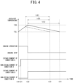
- vertical axis represents, from above, catalyst temperature, engine operation/stop, establishment/non-establishment of the engine stop condition A (indicated as “condition A” in FIGS.), establishment/non-establishment of the engine stop condition B (indicated as "condition B” in FIGS.), and lateral axis represents elapse of time.
- FIG. 3 there will be explained an example of a status transition in the vehicle 1 when the predicted arrival period t(D) to arrive at the start prediction point at which the engine 2 is predicted to be started is relatively long (e.g., when the vehicle 1 travels on relatively-long flat road surface) in a case where the engine 2 is started in response to increase of the driver required torque due to a depression of the accelerator pedal 90. Note that, in FIG. 3
- an actual catalyst temperature indicated with a solid line represents a transition of an actual temperature of the catalyst 2A in a case where the engine 2 is stopped at time t1
- a catalyst temperature prediction value indicated with a broken line represents a transition of a predicted temperature of the catalyst 2A in a case where the engine 2 is continued to be operated to warm-up the catalyst 2A until time t2.
- the actual catalyst temperature can be obtained by, for example, measuring an exhaust gas temperature (the measured exhaust gas temperature can be considered as the actual catalyst temperature).
- the ECU 10 starts calculations of the warm-up completion period t(A), the catalyst performance maintaining period t(B), and the catalyst warm-up efficient period t(C), and comparison between the predicted arrival period t(D) and the catalyst warm-up efficient period t(C). These calculations and comparison are continuously performed until the engine 2 is stopped after the engine 2 is started.
- the predicted arrival period t(D) exceeds the warm-up efficient period t(C) with establishment of the engine stop condition A, stopping the engine 2 to thereby switch the HEV mode to the EV mode.
- the catalyst temperature (actual catalyst temperature) starts to drop.
- the warm-up efficient period t(C) at time t1, as indicated in FIG. 3 is calculated using a prediction value of the catalyst temperature (predicted catalyst temperature) in a case where the catalyst warm-up control (an engine operation to warm-up the catalyst 2A) is continued even after time t1.
- the catalyst temperature reaches the warm-up completion temperature T(H) at time t2, at which the warm-up completion period t(A) elapses from time t1, to thereby stop the catalyst warm-up control (stop the engine 2).
- FIG. 4 there will be explained an example of a status transition in the vehicle 1 when the predicted arrival period t(D) to arrive at the start prediction point at which the engine 2 is predicted to be started is relatively short (e.g., when the vehicle 1 travels on road surface with relatively-large gradient) in a case where the engine 2 is started in response to increase of the driver required torque due to a depression of the accelerator pedal 90.
- the predicted arrival period t(D) to arrive at the start prediction point at which the engine 2 is predicted to be started is relatively short (e.g., when the vehicle 1 travels on road surface with relatively-large gradient) in a case where the engine 2 is started in response to increase of the driver required torque due to a depression of the accelerator pedal 90.
- a solid line as to the catalyst temperature represents a transition of an actual temperature of the catalyst 2A in a case where the engine 2 is stopped at time t12
- a broken line as to the catalyst temperature represents a transition of a predicted temperature of the catalyst 2A in a case where the engine 2 is stopped at a timing between time t11 and time t12.
- the engine 2 is already started in response to the depression of the accelerator pedal 90 to thereby drive the vehicle 1 in the HEV mode. Additionally, at time t10, neither of the engine stop conditions A, B is established, and the catalyst temperature rises due to the engine operation.
- the ECU 10 starts calculations of the warm-up completion period t(A), the catalyst performance maintaining period t(B), and the catalyst warm-up efficient period t(C), and comparison between the predicted arrival period t(D) and the catalyst warm-up efficient period t(C). These calculations and comparison are continuously performed until the engine 2 is stopped after the engine 2 is started.
- the predicted arrival period t(D) falls below the warm-up efficient period t(C) with establishment of the engine stop condition A, not stopping the engine 2 to thereby continue the engine operation to warm-up the catalyst 2A.
- the catalyst temperature rises to the warm-up completion temperature T(H).
- the predicted arrival period t(D) falls below the warm-up efficient period t(C). That is, time t13 at which the predicted arrival period t(D) elapses from time t12 is prior to time t14 at which the warm-up efficient period t(C) elapses from time t12.
- the actual catalyst temperature reaches the warm-up completion temperature T(H) to thereby establish the engine stop condition B. Due thereto, at time t12, the engine 2 is stopped to thereby switch the HEV mode to the EV mode, with which the catalyst temperature starts to drop.
- the catalyst temperature is maintained to be higher than the lower limit temperature T(L) even at time t13 at which the predicted arrival period t(D) elapses and thereafter drops to the lower limit temperature T(L) at t14 at which the predicted arrival period t(D) elapses.
- the catalyst temperature may not be higher than the lower limit temperature T(L), but may be equal thereto. That is, the engine 2 is unnecessary to be operated until the catalyst temperature rises to the warm-up completion temperature T(H).
- the ECU 10 may estimate, during the engine operation in the catalyst warm-up control, the after-engine-stop catalyst performance maintaining period t(E) until the catalyst temperature drops to the lower limit temperature T(L) after the engine 2 is stopped, and stop the engine 2 if the predicted arrival period t(D) is shorter than the estimated after-engine-stop catalyst performance maintaining period t(E).
- the ECU 10 may stop, prior to time t12 at which the catalyst temperature rises to the warm-up completion temperature T(H), the engine 2 if the predicted arrival period t(D) is shorter than the after-engine-stop catalyst performance maintaining period t(E).
- the ECU 10 performs: the catalyst warm-up control of operating the engine 2 to rise the catalyst temperature; the switching control of switching between the EV mode and the HEV mode based on the driver required torque; and the calculations of the start prediction point on the calculated traveling route and the predicted arrival period t(D), the engine 2 being predicted to be, at the start prediction point, started to thereby switch the EV mode to HEV mode, the vehicle 1 being predicted to travel from the current point to the start prediction point for the predicted arrival period t(D).
- the ECU 10 When starting the engine 2 upon establishment of the condition for switching to the HEV mode based on the driver required torque, the ECU 10 starts to calculate: the warm-up completion period t(A) required to rise the catalyst temperature to the warm-up completion temperature T(H) by the catalyst warm-up control; the catalyst performance maintaining period t(B) for which the catalyst temperature of the warm-up completion temperature T(H) drops to, with the engine 2 stopped, the lower limit temperature T(L) down to which the exhaust gas purification performance is maintained; and the catalyst warm-up efficient period t(C) which is the total of the warm-up completion period t(A) and the catalyst performance maintaining period t(B).
- the ECU 10 stops the engine 2 to thereby prohibit the catalyst warm-up control upon establish of the condition for switching to the EV mode based on the driver required torque.
- the ECU 10 prohibits the catalyst warm-up control to stop the engine 2, preventing fuel for catalyst warm-up from being consumed at switching to the EV mode. As a result, it is possible to avoid unnecessary catalyst warm-up control to thereby improve fuel efficiency performance.
- the ECU 10 allows the catalyst warm-up control to be performed if the condition for switching to the EV mode is established.
- the ECU 10 may estimate, during the engine operation in the catalyst warm-up control, the after-engine-stop catalyst performance maintaining period t(E) until the catalyst temperature drops to the lower limit temperature T(L) after the engine 2 is stopped, and stop the engine 2 if the predicted arrival period t(D) is shorter than the estimated after-engine-stop catalyst performance maintaining period t(E).
- the engine 2 is stopped if the predicted arrival period t(D) is shorter than the after-engine-stop catalyst performance maintaining period t(E), shortening a period of time for which the engine 2 is operated to warm-up the catalyst 2A to thereby improve fuel efficiency performance.
- the ECU 10 may respectively calculate:
- the ECU 10 may determine, based on the engine cooling water temperature instead of the catalyst temperature, whether the catalyst warm-up control should be performed.
- a control as to a catalyst warm-up and a control as to an engine operation can be both performed commonly using the engine cooling water temperature greatly related to fuel efficiency performance of the engine 2, improving both the exhaust gas purification performance of the catalyst 2A and the fuel efficiency performance of the engine 2.
- the hybrid vehicle 1 includes the navigation device 12 to calculate a traveling route to a destination position to be set by the driver.
- the ECU 10 acquires the calculated traveling route from the navigation device 12.
- the ECU 10 causes the navigation device 12 to calculate the traveling route to thereby acquire the calculated traveling route therefrom, reducing an operation load of the ECU 10.
Landscapes
- Engineering & Computer Science (AREA)
- Transportation (AREA)
- Mechanical Engineering (AREA)
- Automation & Control Theory (AREA)
- Chemical & Material Sciences (AREA)
- Combustion & Propulsion (AREA)
- Physics & Mathematics (AREA)
- Mathematical Physics (AREA)
- Human Computer Interaction (AREA)
- Hybrid Electric Vehicles (AREA)
Description
- The present invention relates to a control device of a hybrid vehicle.
- There is known from Patent Literature 1 a hybrid vehicle with an engine and a motor as driving sources, in which a timing at which an engine operation is needed is predicted to thereby start, prior to the timing, an engine and complete catalyst warm-up.
- The hybrid vehicle described in Patent Literature 1 is configured such that, in a case where an EV travelable distance calculated based on SOC (state of charge) of a battery is longer than a travel distance to a destination point acquired from a navigation device, an engine start for catalyst warm-up is prohibited due to an arrival to the destination point using a driving force from only the motor. Additionally, the hybrid vehicle described in Patent Literature 1 is configured such that, if the engine start is required even when the catalyst warm-up is prohibited, the prohibition is released. Due thereto, in the hybrid vehicle, it is possible to properly warm-up a catalyst converter when the catalyst warm-up is needed.
- [Patent Literature 1]
JP 2008-120333 A JP2010137605 JP2013001214 JP2016008517
JP2019123330 - However, in the hybrid vehicle described in Patent Literature 1, in a case where the engine is started in response to a rapid increase in a driver required torque during EV traveling to the destination point, the prohibition of the catalyst warm-up is released. For this reason, even if, thereafter, the driver required torque decreases to thereby render a driving force from the engine unnecessary, an engine operation for the catalyst warm-up may be uniformly continued. Hence, in the hybrid vehicle, there is a possibility that fuel efficiency becomes worse due to unnecessary catalyst warm-up.
- Thus, an object of the present invention is to provide a control device of a hybrid vehicle capable of avoiding an unnecessary catalyst warm-up to thereby improve a fuel efficiency performance.
- According to an aspect of the present invention, there is provided a control device of a hybrid vehicle with an EV mode and an HEV mode, the hybrid vehicle including: an engine and a motor as driving sources; and a catalyst to purify an exhaust gas from the engine, the EV mode allowing the hybrid vehicle to travel, with the engine stopped, with a motor torque of the motor, the HEV mode allowing the hybrid vehicle to travel with an engine torque of the engine and the motor torque, the control device including: an acquisition unit to acquire a traveling route from a current point to a destination point; and a control unit to perform a catalyst warm-up control, a switching control, and a calculation, the catalyst warm-up control being of operating the engine to warm-up the catalyst, the switching control being of switching between the EV mode and the HEV mode on conditions therefor based on a driver required torque, the calculation being of calculating a start prediction point on the acquired traveling route, at which the engine is predicted to be started for switching to the HEV mode, and an arrival period of time for which the hybrid vehicle is predicted to travel from the current point to the start prediction point, wherein while the engine is operated on one of the conditions for switching to the HEV mode, the control unit: calculates a warm-up completion period of time for which catalyst temperature rises to a warm-up completion temperature when the catalyst warm-up control is performed, and a catalyst performance maintaining period of time for which the catalyst temperature of the warm-up completion temperature drops to, with the engine stopped, a lower limit temperature down to which an exhaust gas purification performance is maintained, and a catalyst warm-up efficient period of time which is the total of the warm-up completion period and the catalyst performance maintaining period; and prohibits the catalyst warm-up control from being performed if an other condition for switching to the EV mode is established when the calculated arrival period is equal to or longer than the calculated catalyst warm-up efficient period.
- According to the present invention, it is possible to avoid an unnecessary catalyst warm-up to thereby improve a fuel efficiency performance.
-
-
Fig. 1 is a diagram of a vehicle mounted with a control device according to an embodiment of the present invention. -
Fig. 2 is a flow chart showing operations of the control device. -
Fig. 3 is a time chart showing an example of a status transition in the vehicle when a predicted period of time for arrival at an engine start in response to an increase in a driver required torque is relatively long. -
Fig. 4 is a time chart showing an example of a status transition in the vehicle when a predicted period of time for arrival at an engine start in response to an increase in a driver required torque is relatively short. - A control device according to an embodiment of the present invention is mounted on a hybrid vehicle with an EV mode and an HEV mode, the hybrid vehicle including: an engine and a motor as driving sources; and a catalyst to purify an exhaust gas from the engine, the EV mode allowing the hybrid vehicle to travel, with the engine stopped, with a motor torque of the motor, the HEV mode allowing the hybrid vehicle to travel with an engine torque of the engine and the motor torque, the control device including: an acquisition unit to acquire a traveling route from a current point to a destination point; and a control unit to perform a catalyst warm-up control, a switching control, and a calculation, the catalyst warm-up control being of operating the engine to warm-up the catalyst, the switching control being of switching between the EV mode and the HEV mode on conditions therefor based on a driver required torque, the calculation being of calculating a start prediction point on the acquired traveling route, at which the engine is predicted to be started for switching to the HEV mode, and an arrival period of time for which the hybrid vehicle is predicted to travel from the current point to the start prediction point, wherein while the engine is operated on one of the conditions for switching to the HEV mode, the control unit: calculates a warm-up completion period of time for which catalyst temperature rises to a warm-up completion temperature when the catalyst warm-up control is performed, and a catalyst performance maintaining period of time for which the catalyst temperature of the warm-up completion temperature drops to, with the engine stopped, a lower limit temperature down to which an exhaust gas purification performance is maintained, and a catalyst warm-up efficient period of time which is the total of the warm-up completion period and the catalyst performance maintaining period; and prohibits the catalyst warm-up control from being performed if an other condition for switching to the EV mode is established when the calculated arrival period is equal to or longer than the calculated catalyst warm-up efficient period.
- Hereinafter, referring to Figs., a vehicle mounted with a control device according to an embodiment of the present invention will be described. As shown in
FIG. 1 , the vehicle 1 includes anengine 2 and amotor generator 3 as driving sources, abattery 31 to which/from which electric power is supplied from/to themotor generator 3, a transmission 4, adifferential 5,wheels 6, and an ECU 10 (Electronic Control Unit). - The
engine 2 is formed with cylinders, being configured to perform, for each cylinder, a series of four steps of an intake step, a compression step, an expansion step and an exhaust step. - The
engine 2 includes acatalyst 2A to clean an exhaust gas from theengine 2. Thecatalyst 2A has a characteristic of providing the purification performance when catalyst temperature is an activation temperature or higher. - The
engine 2 is connected with an ISG 20 (Integrated Starter Generator). Specifically, the ISG 20 is connected to a crankshaft of theengine 2 via abelt 21 and the like. - The ISG 20 has a motor function of rotating with supplied electric power to thereby rotate the
engine 2 and a generator function of converting a rotation inputted from the crankshaft into electric power. - The
motor generator 3 has a function of applying a driving force by an electric power supplied from thebattery 31 through aninverter 30 and another function of generating a regenerative electric power with a counter driving force inputted from thedifferential 5. - The
inverter 30 is controlled by theECU 10 to convert DC power supplied from thebattery 31 into three-phase AC power and supply the converted AC power to themotor generator 3 and to convert three-phase AC power generated by themotor generator 3 into DC power and charge thebattery 31 with the converted DC power. - The
battery 31 is a secondary battery such as a lithium ion battery. - The transmission 4 is configured to change, at a shift ratio corresponding to selected one of shift stages, a rotation speed inputted to an input shaft thereof from the
engine 2 and output it from an output shaft thereof. The transmission 4 is AMT (Automated Manual Transmission) in which shift operations in a parallel shaft gear type manual transmission are automated. - A shift stage switching in the transmission 4 is performed by a
shift actuator 44. Theshift actuator 44 is connected to theECU 10, to be controlled thereby. The output shaft of the transmission 4 is connected to left andright wheels 6 via thedifferential 5, the output shaft of the transmission 4 being connected with an output shaft of themotor generator 3. Thus, the vehicle 1 is a hybrid vehicle travelable with a driving force from at least one of theengine 2 and themotor generator 3. - As shift stages to be established in the transmission 4, there are first (low-speed) to fifth (high-speed) forward shift stages and a reverse shift stage. The number of forward shift stages is to be determined depending on the specification of the vehicle 1, not limited to 5 (first to fifth shift stages). The transmission 4 includes synchronizing mechanisms (synchromesh devices) for not only the forward shift stages but also the reverse shift stage.
- The shift stages in the transmission 4 are switched therebetween in accordance with a shift position of a
shift lever 40 to be operated by a driver. The shift position of theshift lever 40 is detected by ashift position sensor 41. Theshift position sensor 41 is connected to theEUC 10, to send the detection result thereto. - As the shift position, the
shift lever 40 includes, e.g., parking position (P range), reverse position (R range), neutral position (N range), and forward position (D range), one of which is selected by the driver. - For example, when the driver selects D range as the shift position of the
shift lever 40, theECU 10 drives the shift andclutch actuators accelerator pedal sensor 91 and the like to thereby establish one of the first to fifth forward shift stages to change the rotation speed. - In addition, when the driver switches the shift position from the selected D range to R range, the
ECU 10 drives the shift andclutch actuators - D range and R range are shift positions at which the vehicle is allowed to travel, each of which corresponds to a traveling position. P range and N range are shift positions at which the
engine 2 is allowed to start, each of which corresponds to a start position. - The transmission 4 is provided with a
neutral switch 42 connected to theECU 10. Theneutral switch 42 is used to detect that none of the shift stages is established in the transmission 4, i.e., to detect a neutral state, theneutral switch 42 being configured to be turned ON when the transmission 4 is in the neutral state. - A clutch 7 is provided on a power transmission path between the
engine 2 and the transmission 4. The clutch 7 is a friction clutch, for example. Theengine 2 and the transmission 4 are interconnected via the clutch 7. The clutch 7 is configured to connect/disconnect theengine 2 and the transmission 4 to/from each other. The clutch 7 constitutes a power transmission mechanism. - Thus, the transmission 4 is transmitted with power from the
engine 2 via the clutch 7, which is configured to switch between the shift stages in response to a shift operation. The clutch 7 includes a clutch disc connected to the input shaft of the transmission 4 so as to rotate together therewith. Hence, a rotation number of the clutch disc (hereinafter also referred to as "rotation number of clutch 7") is equal to that of the input shaft of the transmission 4. - The clutch 7 is actuated by the
clutch actuator 70 to thereby be switched among an engagement state where power is transmitted between theengine 2 and themotor generator 3, a disengagement state (release state) where no power is transmitted therebetween, and a half-clutch state where torque is transmitted therebetween with rotation difference (i.e., while theengine 2 and themotor generator 3 rotate with different rotation speeds). Theclutch actuator 70 is connected to theECU 10, to be controlled thereby. - The clutch 7 is provided with a clutch
rotation number sensor 43 to detect rotation number of the clutch 7. The clutchrotation number sensor 43 is connected to theECU 10 to send the detection result thereto. The clutchrotation number sensor 43 is not configured to detect a rotation direction of the clutch 7. - The
ECU 10 controls theclutch actuator 70 in accordance with a depression amount of aclutch pedal 71 to be operated by the driver, as if a manual clutch is operated. - The depression amount of the
clutch pedal 71 is detected by aclutch pedal sensor 72. Theclutch pedal sensor 72 is connected to theECU 10, being configured to send a signal in response to the depression amount of theclutch pedal 71 to theECU 10. - The vehicle 1 includes an
accelerator pedal 90 to be operated by the driver. A depression amount of theaccelerator pedal 90 is detected by anaccelerator pedal sensor 91. Theaccelerator pedal sensor 91 is connected to theECU 10, being configured to detect the depression amount of theaccelerator pedal 90 as an accelerator opening and send a signal in response to the detected accelerator opening to theECU 10. - The vehicle 1 includes a
brake pedal 92 to be operated by the driver. A depression amount of thebrake pedal 92 is detected by abrake pedal sensor 93. Thebrake pedal sensor 93 is connected to theECU 10, being configured to send a signal in response to the depression amount of thebrake pedal 92 to theECU 10. - The vehicle 1 includes a
navigation device 12. Thenavigation device 12 includes GPS (Global Positioning System) to position the vehicle 1 to thereby acquire a current position thereof, and a storage device to store a map, thenavigation device 12 being configured to calculate a traveling route from the current position to a destination position and a travel distance thereof. As thenavigation device 12, an in-vehicle navigation device can be used. Alternatively, a smart phone with a navigation function may be used, being of an occupant in the vehicle 1. - The
ECU 10 is constituted by a computer unit including a Central Processing Unit (CPU), a Random Access Memory (RAM), a Read Only Memory (ROM), a flash memory to store a backup data and the like, and input and output ports. - The ROM of the computer unit stores a program for causing the computer unit to function as the
ECU 10, with various constants and maps. That is, the CPU executes the program stored in the ROM using the RAM as an operation area, causing the computer unit to function as theECU 10. - The
ECU 10 is connected with avehicle speed sensor 11 in addition to the above-mentioned sensors. Thevehicle speed sensor 11 is configured to detect a vehicle speed of the vehicle 1 and send the detection result to theECU 10. - The
ECU 10 is configured to switch between control modes for the vehicle 1. As the control modes, there are an electric vehicle traveling mode (hereinafter referred to as "EV mode") and a hybrid traveling mode (hereinafter referred to as "HEV mode"), for example. - In the EV mode, the vehicle 1 is driven, with the
engine 2 stopped, with motor torque of themotor generator 3. Specifically, in the EV mode, themotor generator 3 is controlled so as to satisfy a driver required torque with only motor torque of themotor generator 3. Note that in the EV mode, the clutch 7 is released (i.e., is placed in the disengagement state). - In the HEV mode, the vehicle 1 is driven with at least engine torque of the
engine 2. Specifically, in the HEV mode, the vehicle 1 is driven with only the engine torque or both of the engine torque and the motor torque. For example, in the HEV mode, themotor generator 3 and theengine 2 are both controlled so as to satisfy the driver required torque with total torque of the motor torque and the engine torque. As such a case where the vehicle 1 is driven with the total torque, there is a case where theengine 2 outputs the engine torque to compensate the shortage of the motor torque to the driver required torque or a case where themotor generator 3 outputs the motor torque to compensate the shortage of the engine torque to the driver required torque. Note that in the HEV mode, the clutch 7 is engaged (i.e., is placed in the engagement state). - The
ECU 10 is connected with thenavigation device 12. TheECU 10 acquires, from thenavigation device 12, the traveling route and distance from the current position to the destination position. TheECU 10 constitutes an acquisition unit of the present invention. - The
ECU 10 switches between the EV mode and the HEV mode based on the driver required torque and SOC (State Of Charge) of thebattery 31, the driver required torque being determined based on the accelerator opening and a rotation number of theengine 2. - When, during the EV mode, the depression amount of the
accelerator pedal 90 increases to thereby disenable a maximum motor torque (motor outputtable torque to be determined in accordance with the SOC of the battery 31) in accordance with the SOC of thebattery 31 to satisfy the driver required torque, theECU 10 switches the control mode from the EV mode to the HEV mode. Upon switching from the EV mode to the HEV mode, theengine 2 is started. In the HEV mode, theengine 2 and themotor generator 3 are both controlled so as to satisfy the driver required torque with the total torque of the engine and motor torques. - On the other hand, when, during the HEV mode, the depression amount of the
accelerator pedal 90 decreases to thereby enable the maximum motor torque in accordance with the SOC of thebattery 31 to satisfy the driver required torque, theECU 10 switches the control mode from the HEV mode to the EV mode. Upon switching from the HEV mode to the EV mode, theengine 2 is stopped. - Additionally, the
ECU 10 performs a catalyst warm-up control of operating theengine 2 to rise temperature of thecatalyst 2A (hereinafter also referred to as "catalyst temperature"). - Thus, the vehicle 1 is a hybrid vehicle traveling with the EV mode and the HEV mode to be switched therebetween, in which the
engine 2 is intermittently operated during vehicle traveling. Due thereto, when theengine 2 is started upon switching from the EV mode to the HEV mode, thecatalyst 2A may not become an activation temperature. If the catalyst temperature is low (e.g., catalyst temperature is yet to rise to the activation temperature), an exhaust gas purification performance may become worse. Note that the exhaust gas purification performance means a performance with which exhaust gas is purified. - For this reason, in order to prevent the exhaust gas purification performance from becoming worse, it is preferable that the catalyst warm-up control (hereinafter also referred to as "catalyst warm-up") is performed prior to a timing, at which the EV mode is predicted to be switched to the HEV mode, to thereby rise the catalyst temperature to the activation temperature or higher so as to allow the exhaust gas purification performance of the
catalyst 2A to be sufficiently provided upon start of the HEV mode. - Accordingly, the
ECU 10 calculates an arrival timing, at which the vehicle 1 arrives at a point where the EV mode is predicted to be switched to the HEV mode, based on information including the traveling route to the destination position acquired from thenavigation device 12, and performs the catalyst warm-up control prior to the arrival timing. - Specifically, the
ECU 10, in real-time, calculates a start prediction point on the traveling route, at which theengine 2 is predicted to be started due to switching to the HEV mode, and an arrival period t (D) of time (i.e., a period of time required to arrive at the start prediction point from the current point), for which the vehicle is predicted to travel from the current point to the calculated start prediction point. Then, theECU 10 performs the catalyst warm-up control at a timing before the predicted arrival period t (D) becomes zero (i.e., at a timing before arriving at the calculated start prediction point). - The start prediction point is determined mainly based on the current SOC of the
battery 31, a traveling load on the traveling route (a road surface condition between the current point and the destination point, such as an uphill road), and a current state of themotor generator 3 or theinverter 30. TheECU 10 determines, as the start prediction point, a point on the traveling route, at which the SOC of thebattery 31 is predicted to drop to a predetermined value, for example. Alternatively, theECU 10 may determine, as the start prediction point, a point on the traveling route, at which the traveling load on the traveling route is predicted to exceed the maximum motor torque of themotor generator 3. Alternatively, theECU 10 may determine, as the start prediction point, a point on the traveling route, at which temperature of themotor generator 3 or theinverter 30 is predicted to become a predetermined temperature or higher to thereby be in a hot-temperature state. - By the way, when the depression amount of the
accelerator pedal 90 is increased by the driver to thereby request the engine torque to compensate the shortage of the motor torque to the driver required torque, theECU 10 determines that a condition for switching from the EV mode to the HEV mode is established and following the determination, starts theengine 2 to switch the EV mode to the HEV mode. Thereafter, when the depression amount of theaccelerator pedal 90 is decreased by the driver to thereby render the engine torque unnecessary to compensate the shortage of the motor torque to the driver required torque, theECU 10 determines that a condition for switching from the HEV mode to the EV mode is established and following the determination, stops theengine 2 to switch the HEV mode to the EV mode. - Such an engine start/stop in response to the driver required torque is performed in accordance with the depression amount of the
accelerator pedal 90 to be operated by the driver and thus, is difficult to be accurately determined in advance whether to be performed (i.e., it is difficult to accurately predict when/what amount the driver depresses the accelerator pedal 90). In other words, the engine start/stop in response to the driver required torque may suddenly occur before the vehicle 1 arrives at the start prediction point. - In consideration of the above-mentioned difficulty, for example, even if the catalyst warm-up control is, upon establishment of the condition for switching to the EV mode, performed so as to continue an engine operation until warm-up of the
catalyst 2A is completed (i.e., until catalyst temperature rises to a warm-up completion temperature T(H)), the exhaust gas purification performance may be or may not be sufficiently maintained until the vehicle 1 arrives at the start prediction point (i,e,, there is a case where the exhaust gas purification performance is/is not sufficiently maintained until the vehicle 1 arrives at the start prediction point). In the latter case, unnecessary warm-up is to be performed for thecatalyst 2A, worsening fuel efficiency performance. - For this reason, in the present embodiment, when the engine is started after the condition for switching to the HEV mode based on the driver required torque is established, the
ECU 10 starts to calculate the followings: - a warm-up completion period of time t(A) required to rise catalyst temperature to the warm-up completion temperature T(H) by the catalyst warm-up control;
- a catalyst performance maintaining period of time t(B) for which the catalyst temperature of the warm-up completion temperature T(H) drops to, with the
engine 2 stopped, a lower limit temperature T(L) down to which the exhaust gas purification performance is maintained; and - a catalyst warm-up efficient period of time t(C) which is the total of the warm-up completion period t(A) and the catalyst performance maintaining period t(B).
- Note that the lower limit temperature T(L) is e.g., the activation temperature of the
catalyst 2A. - The
ECU 10 calculates these periods (the warm-up completion period t(A), the catalyst performance maintaining period t(B), and the catalyst warm-up efficient period t(C)) as long as theengine 2 is operated (i.e., only during the engine operation), while monitoring actual temperature of thecatalyst 2A and the like. - Specifically, the
ECU 10 calculates the warm-up completion period t(A) based on the warm-up completion temperature T(H), the current catalyst temperature, and at least one of a current outside air temperature, a vehicle speed of the vehicle 1 on the calculated traveling route, and a driving force of the vehicle 1 on the calculated traveling route. TheECU 10 calculates the catalyst performance maintaining period t(B) based on a difference between the warm-up completion temperature T(H) and the lower limit temperature T(L), the current outside air temperature, and the vehicle speed on the calculated traveling route. - Then, when the predicted arrival period t(D) is equal to or longer than the calculated catalyst warm-up efficient period t(C), the
ECU 10 prohibits the catalyst warm-up control if the condition for switching to the EV mode is established (i.e., stops theengine 2 upon establishment of this condition). - On the other hand, when the predicted arrival period t(D) is shorter than the calculated catalyst warm-up efficient period t(C), the
ECU 10 allows the catalyst warm-up control even if the condition for switching to the EV mode is established (i.e., continues, even after establishment of this condition, the engine operation to thereby warm-up thecatalyst 2A). - In this case (in a case where the
ECU 10 allows the catalyst warm-up control following the establishment of said condition), theECU 10 may estimate, during the engine operation in the catalyst warm-up control, an after-engine-stop catalyst performance maintaining period of time t(E) until catalyst temperature drops to the lower limit temperature T(L) after theengine 2 is stopped, and stop theengine 2 if the predicted arrival period t(D) is shorter than the estimated after-engine-stop catalyst performance maintaining period t(E). Note that theECU 10 can estimate the after-engine-stop catalyst performance maintaining period t(E) based on the fact that a drop rate (inclination) of catalyst temperature when theengine 2 is stopped is constant. - There is a correlation between catalyst temperature and engine cooling water temperature. Due thereto, the
ECU 10 may store, in advance, threshold values for the engine cooling water temperature respectively corresponding to the warm-up completion temperature T(H) and the lower limit temperature T(L) and compare the engine cooling water temperature with the stored threshold values, thereby determining whether the catalyst warm-up control should be performed. - Specifically, the
ECU 10 may calculate: - a period of time for which the engine cooling water temperature of the
engine 2 rises to a first of the threshold values which corresponds to the warm-up completion temperature T(H), as the warm-up completion period t(A); - a period of time for which the engine cooling water temperature of the
engine 2 drops to a second of the threshold values which corresponds to the lower limit temperature T(L), as the catalyst performance maintaining period t(B); and - total of these calculated periods, as the catalyst warm-up efficient period t(C).
- That is, the
ECU 10 may determine, based on an engine cooling water temperature instead of catalyst temperature, whether the catalyst warm-up control should be performed. - Referring to
FIG. 2 , a control operation to be performed in the control device according to the present embodiment will be explained. This operation is repeated at a short interval. - As shown in
FIG. 2 , theECU 10 determines whether an engine start condition is established (step S1). If "YES" at step S1, theECU 10 proceeds to step S2. Otherwise (if "NO" at step S1), theECU 10 terminates this operation to thereby repeat it. - The engine start condition is a condition for switching from the EV mode to the HEV mode, based on e.g., SOC of the
battery 31 and an operation amount (depression amount) of theaccelerator pedal 90 by the driver. TheECU 10 determines, at step S1, that the engine start condition is established if the driver required torque determined based on the operation amount of theaccelerator pedal 90 reaches the maximum motor torque of themotor generator 3 estimated based on SOC of thebattery 31 and the like, thereafter starting theengine 2 at step S2. - Thereafter, the
ECU 10 determines, at step S3, whether the destination point and the calculated traveling route are both set in thenavigation device 12. If "YES" at step S3, theECU 10 proceeds to step S4, otherwise proceeding to step S7. - At step S4, the
ECU 10 calculates the start prediction point, at which theengine 2 is predicted to be started, and the arrival period t(D) for which the vehicle 1 is predicted to travel from the current point to the start prediction point, to thereby determine whether or not the predicted arrival period t(D) is equal to or longer than the catalyst warm-up efficient period t(C). If "YES" at step S4, theECU 10 proceeds to step S5, otherwise proceeding to step S7. - At step S5, the
ECU 10 determines whether an engine stop condition A is established. If "YES" at step S5, theECU 10 proceeds to step S6, otherwise returning to step S3. - The engine stop condition A is a condition on which the
engine 2 is stopped with switching to the EV mode, not depending on warm-up state of thecatalyst 2A. For example, the engine stop condition A is based on SOC of thebattery 31 and an operation amount (depression amount) of theaccelerator pedal 90 by the driver. Specifically, theECU 10 determines, at step S5, that the engine stop condition A is established if the driver required torque determined based on the operation amount of theaccelerator pedal 90 falls below the maximum motor torque of themotor generator 3 estimated based on SOC of thebattery 31 and the like, thereafter proceeding to step S6 to stop theengine 2 and terminating this operation. - Thus, when the predicted arrival period t(D) is equal to or longer than the catalyst warm-up efficient period t(C) ("YES" at step S4), the
ECU 10 prohibits the catalyst warm-up control (an engine operation to warm-up thecatalyst 2A) from being performed if the engine stop condition A for switching to the EV mode based on the driver required torque ("YES" at step S5). - At step S7, the
ECU 10 determines whether an engine stop condition B is established, and proceeds to step S6 if the engine stop condition B is established, otherwise returning to step S3. - The engine stop condition B is an engine stop condition on which the
engine 2 is stopped with switching to the EV mode, depending on warm-up state of thecatalyst 2A. That is, the engine stop condition B includes, in addition to the engine stop condition A, a condition for the catalyst temperature or the engine cooling water temperature as to catalyst warm-up. For example, if the catalyst temperature is the lower limit temperature T(L) or higher, down to which the exhaust gas purification performance is maintained, when the engine stop condition A is established, theECU 10 determines that the engine stop condition B is established, proceeding to step S6 to stop theengine 2 and thereafter terminating this operation. In other words, as to determination of the engine stop condition B, theECU 10 never determines that the engine stop condition B is established if the catalyst temperature is lower than the lower limit temperature T(L) even when the engine stop condition A is established. - Thus, when the predicted arrival period t(D) is shorter than the catalyst warm-up efficient period t(C) ("NO" at step S4), even if the engine stop condition A for switching to the EV mode based on the driver required torque, the
ECU 10 does not immediately stop theengine 2 but allows the catalyst warm-up control to be performed. That is, in this case, theECU 10 continues the engine operation to warm-up thecatalyst 2A even after the engine stop condition A is established, and stops theengine 2 upon establishment of the engine stop condition B depending on warm-up state of thecatalyst 2A. - Referring to
FIGS. 3 and4 , a status transition of the vehicle 1 during the above-mentioned control operation to be performed by theECU 10 will be explained. In each ofFIGS. 3 and4 , vertical axis represents, from above, catalyst temperature, engine operation/stop, establishment/non-establishment of the engine stop condition A (indicated as "condition A" in FIGS.), establishment/non-establishment of the engine stop condition B (indicated as "condition B" in FIGS.), and lateral axis represents elapse of time. - Firstly, referring to
FIG. 3 , there will be explained an example of a status transition in the vehicle 1 when the predicted arrival period t(D) to arrive at the start prediction point at which theengine 2 is predicted to be started is relatively long (e.g., when the vehicle 1 travels on relatively-long flat road surface) in a case where theengine 2 is started in response to increase of the driver required torque due to a depression of theaccelerator pedal 90. Note that, inFIG. 3 , an actual catalyst temperature indicated with a solid line represents a transition of an actual temperature of thecatalyst 2A in a case where theengine 2 is stopped at time t1, and a catalyst temperature prediction value indicated with a broken line represents a transition of a predicted temperature of thecatalyst 2A in a case where theengine 2 is continued to be operated to warm-up thecatalyst 2A until time t2. The actual catalyst temperature can be obtained by, for example, measuring an exhaust gas temperature (the measured exhaust gas temperature can be considered as the actual catalyst temperature). - In
FIG. 3 , at time t0, theengine 2 is already started in response to the depression of theaccelerator pedal 90 to thereby drive the vehicle 1 in the HEV mode. Additionally, at time t0, neither of the engine stop conditions A, B is established, and the catalyst temperature rises due to the engine operation. - At this time t0, the
ECU 10 starts calculations of the warm-up completion period t(A), the catalyst performance maintaining period t(B), and the catalyst warm-up efficient period t(C), and comparison between the predicted arrival period t(D) and the catalyst warm-up efficient period t(C). These calculations and comparison are continuously performed until theengine 2 is stopped after theengine 2 is started. - Thereafter, at time t1, the predicted arrival period t(D) exceeds the warm-up efficient period t(C) with establishment of the engine stop condition A, stopping the
engine 2 to thereby switch the HEV mode to the EV mode. At time t1, since theengine 2 is stopped, the catalyst temperature (actual catalyst temperature) starts to drop. - The warm-up efficient period t(C) at time t1, as indicated in
FIG. 3 , is calculated using a prediction value of the catalyst temperature (predicted catalyst temperature) in a case where the catalyst warm-up control (an engine operation to warm-up thecatalyst 2A) is continued even after time t1. As shown inFIG. 3 , in a case where theengine 2 is not stopped at time t1 but is continued to be operated to warm-up thecatalyst 2A even after time t1, it is predicted that the catalyst temperature reaches the warm-up completion temperature T(H) at time t2, at which the warm-up completion period t(A) elapses from time t1, to thereby stop the catalyst warm-up control (stop the engine 2). Then, it is also predicted that the catalyst temperature continues to drop after time t2 to thereby be lower than the lower limit temperature T(L) at time t3 at which the catalyst performance maintaining period t(B) elapses from time t2. - That is, in the case shown in
FIG. 3 , at the timing of time t1, it is predicted that: although the vehicle 1 arrives, at time t4 at which the predicted arrival period t(D) elapses from time t1, at the start prediction point to thereby start theengine 2, the catalyst temperature drops below the lower limit temperature T(L) at time t3 prior to time t4. Hence, there is a high possibility that the catalyst temperature is not maintained to be the lower limit temperature T(L) or higher until time t4 at which the vehicle 1 arrives at the start prediction point even if theengine 2 is not stopped at time t1 but is continued to be operated to warm-up thecatalyst 2A until time t2. - Thus, as shown in
FIG. 3 , in a period where theengine 2 is operated (a period from time t0 to time t1 inFIG. 3 ), if the predicted arrival period t(D) is the warm-up efficient period t(C) or longer, theengine 2 is stopped upon establishment of the engine stop condition A (at time t1 inFIG. 3 ). Note that the catalyst temperature drops due to the engine stop at time t1 but rises at time t4, at which the vehicle 1 arrives at the start prediction point, due to an engine start to be performed thereat. - Secondly, referring to
FIG. 4 , there will be explained an example of a status transition in the vehicle 1 when the predicted arrival period t(D) to arrive at the start prediction point at which theengine 2 is predicted to be started is relatively short (e.g., when the vehicle 1 travels on road surface with relatively-large gradient) in a case where theengine 2 is started in response to increase of the driver required torque due to a depression of theaccelerator pedal 90. Note that, as well asFIG. 3 , inFIG. 4 , a solid line as to the catalyst temperature represents a transition of an actual temperature of thecatalyst 2A in a case where theengine 2 is stopped at time t12, and a broken line as to the catalyst temperature represents a transition of a predicted temperature of thecatalyst 2A in a case where theengine 2 is stopped at a timing between time t11 and time t12. - In
FIG. 4 , at time t10, theengine 2 is already started in response to the depression of theaccelerator pedal 90 to thereby drive the vehicle 1 in the HEV mode. Additionally, at time t10, neither of the engine stop conditions A, B is established, and the catalyst temperature rises due to the engine operation. - At this time t10, the
ECU 10 starts calculations of the warm-up completion period t(A), the catalyst performance maintaining period t(B), and the catalyst warm-up efficient period t(C), and comparison between the predicted arrival period t(D) and the catalyst warm-up efficient period t(C). These calculations and comparison are continuously performed until theengine 2 is stopped after theengine 2 is started. - Thereafter, at time t11, the predicted arrival period t(D) falls below the warm-up efficient period t(C) with establishment of the engine stop condition A, not stopping the
engine 2 to thereby continue the engine operation to warm-up thecatalyst 2A. - Thereafter, at time t12, the catalyst temperature rises to the warm-up completion temperature T(H). Also thereat, the predicted arrival period t(D) falls below the warm-up efficient period t(C). That is, time t13 at which the predicted arrival period t(D) elapses from time t12 is prior to time t14 at which the warm-up efficient period t(C) elapses from time t12. In addition, at time t12, the actual catalyst temperature reaches the warm-up completion temperature T(H) to thereby establish the engine stop condition B. Due thereto, at time t12, the
engine 2 is stopped to thereby switch the HEV mode to the EV mode, with which the catalyst temperature starts to drop. The catalyst temperature is maintained to be higher than the lower limit temperature T(L) even at time t13 at which the predicted arrival period t(D) elapses and thereafter drops to the lower limit temperature T(L) at t14 at which the predicted arrival period t(D) elapses. - Note that in
FIG. 4 , in order to explain the transition of the actual catalyst temperature, theengine 2 is stopped even after time t13 but actually is to be started upon elapse of the predicted arrival period t(D). - Thus, as shown in
FIG. 4 , in a period where theengine 2 is operated (a period from time t10 to time t12 inFIG. 4 ), if the predicted arrival period t(D) is shorter than the warm-up efficient period t(C), theengine 2 is stopped upon establishment of not the engine stop condition A but the engine stop condition B. - At time t13 at which the
engine 2 is predicted to be started, in consideration of maintaining the exhaust gas purification performance, the catalyst temperature may not be higher than the lower limit temperature T(L), but may be equal thereto. That is, theengine 2 is unnecessary to be operated until the catalyst temperature rises to the warm-up completion temperature T(H). - Thus, in a case of allowing the catalyst warm-up control to be performed even upon establishment of the engine stop condition A, the
ECU 10 may estimate, during the engine operation in the catalyst warm-up control, the after-engine-stop catalyst performance maintaining period t(E) until the catalyst temperature drops to the lower limit temperature T(L) after theengine 2 is stopped, and stop theengine 2 if the predicted arrival period t(D) is shorter than the estimated after-engine-stop catalyst performance maintaining period t(E). - That is, in a case of allowing the catalyst warm-up control to be performed to thereby continue, even after time t11, the engine operation to warm-up the
catalyst 2A, theECU 10 may stop, prior to time t12 at which the catalyst temperature rises to the warm-up completion temperature T(H), theengine 2 if the predicted arrival period t(D) is shorter than the after-engine-stop catalyst performance maintaining period t(E). - As mentioned above, in the present embodiment, the
ECU 10 performs: the catalyst warm-up control of operating theengine 2 to rise the catalyst temperature; the switching control of switching between the EV mode and the HEV mode based on the driver required torque; and the calculations of the start prediction point on the calculated traveling route and the predicted arrival period t(D), theengine 2 being predicted to be, at the start prediction point, started to thereby switch the EV mode to HEV mode, the vehicle 1 being predicted to travel from the current point to the start prediction point for the predicted arrival period t(D). - When starting the
engine 2 upon establishment of the condition for switching to the HEV mode based on the driver required torque, theECU 10 starts to calculate: the warm-up completion period t(A) required to rise the catalyst temperature to the warm-up completion temperature T(H) by the catalyst warm-up control; the catalyst performance maintaining period t(B) for which the catalyst temperature of the warm-up completion temperature T(H) drops to, with theengine 2 stopped, the lower limit temperature T(L) down to which the exhaust gas purification performance is maintained; and the catalyst warm-up efficient period t(C) which is the total of the warm-up completion period t(A) and the catalyst performance maintaining period t(B). - When the predicted arrival period t(D) is the catalyst warm-up efficient period t(C) or longer, the
ECU 10 stops theengine 2 to thereby prohibit the catalyst warm-up control upon establish of the condition for switching to the EV mode based on the driver required torque. - Thus, when it is predicted that even if the
engine 2 is continued to be operated until the catalyst warm-up is completed, the exhaust gas purification performance is not sufficiently maintained until the vehicle 1 arrives at the start prediction point, at which theengine 2 is to be started, after the catalyst warm-up is completed, theECU 10 prohibits the catalyst warm-up control to stop theengine 2, preventing fuel for catalyst warm-up from being consumed at switching to the EV mode. As a result, it is possible to avoid unnecessary catalyst warm-up control to thereby improve fuel efficiency performance. - Additionally, when the predicted arrival period t(D) is shorter than the catalyst warm-up efficient period t(C), the
ECU 10 allows the catalyst warm-up control to be performed if the condition for switching to the EV mode is established. - Thereby, when it is predicted that the exhaust gas purification performance is sufficiently maintained, even after the catalyst warm-up is completed, until the vehicle 1 arrives at the start prediction point at which the
engine 2 is to be started, theengine 2 is not immediately stopped at switching to the EV mode to thereby warm-up thecatalyst 2A, improving the exhaust gas purification performance at switching to the HEV mode. - In such a case where the
ECU 10 allows the catalyst warm-up control, it may estimate, during the engine operation in the catalyst warm-up control, the after-engine-stop catalyst performance maintaining period t(E) until the catalyst temperature drops to the lower limit temperature T(L) after theengine 2 is stopped, and stop theengine 2 if the predicted arrival period t(D) is shorter than the estimated after-engine-stop catalyst performance maintaining period t(E). - Thereby, even before the catalyst temperature rises to the warm-up completion temperature T(H), the
engine 2 is stopped if the predicted arrival period t(D) is shorter than the after-engine-stop catalyst performance maintaining period t(E), shortening a period of time for which theengine 2 is operated to warm-up thecatalyst 2A to thereby improve fuel efficiency performance. - Instead of the above-mentioned warm-up completion period t(A), the catalyst performance maintaining period t(B), and the catalyst warm-up efficient period t(C), the
ECU 10 may respectively calculate: - the period for which the engine cooling water temperature of the
engine 2 rises to the first threshold value which corresponds to the warm-up completion temperature T(H); - the period for which the engine cooling water temperature of the
engine 2 drops to the second threshold value which corresponds to the lower limit temperature T(L); and - the total of these calculated periods.
- That is, the
ECU 10 may determine, based on the engine cooling water temperature instead of the catalyst temperature, whether the catalyst warm-up control should be performed. - Thereby, a control as to a catalyst warm-up and a control as to an engine operation can be both performed commonly using the engine cooling water temperature greatly related to fuel efficiency performance of the
engine 2, improving both the exhaust gas purification performance of thecatalyst 2A and the fuel efficiency performance of theengine 2. - The hybrid vehicle 1 includes the
navigation device 12 to calculate a traveling route to a destination position to be set by the driver. TheECU 10 acquires the calculated traveling route from thenavigation device 12. - Thus, the
ECU 10 causes thenavigation device 12 to calculate the traveling route to thereby acquire the calculated traveling route therefrom, reducing an operation load of theECU 10. - Although the embodiment of the present invention is disclosed above, it is obvious that those skilled in the art can modify it without departing from the scope of the present invention as defined by the appended claims.
-
- 1: vehicle (hybrid vehicle)
- 2: engine
- 2A: catalyst
- 3: motor generator (motor)
- 10: ECU (acquisition unit, control unit)
- 12: navigation device
- t(A): warm-up completion period of time
- t(B): catalyst performance maintaining period of time
- t(C): catalyst warm-up efficient period of time
- t(D): predicted arrival period of time
- T(H): warm-up completion temperature
- T(L): lower limit temperature
Claims (5)
- A control device of a hybrid vehicle (1) with an EV mode and an HEV mode, the hybrid vehicle (1) including:an engine (2) and a motor (3) as driving sources; anda catalyst (2A) to purify an exhaust gas from the engine (2),the EV mode allowing the hybrid vehicle (1) to travel, with the engine stopped, with a motor torque of the motor (3),the HEV mode allowing the hybrid vehicle (1) to travel with an engine torque of the engine (2) and the motor torque,the control device comprising:an acquisition unit (10) to acquire a traveling route from a current point to a destination point; anda control unit (10) to perform a catalyst warm-up control, a switching control, and a calculation,the catalyst warm-up control being of operating the engine (2) to rise catalyst temperature,the switching control being of switching between the EV mode and the HEV mode on conditions therefor based on a driver required torque,the calculation being of calculating a start prediction point on the acquired traveling route, at which the engine (2) is predicted to be started for switching to the HEV mode, and an arrival period of time (t(D)) for which the hybrid vehicle (1) is predicted to travel from the current point to the start prediction point,wherein while the engine (2) is operated on one of the conditions for switching to the HEV mode, the control unit (10):
calculates a warm-up completion period of time (t(A)) for which the catalyst temperature rises to a warm-up completion temperature (T(H)) when the catalyst warm-up control is performed, and a catalyst performance maintaining period of time (t(B)) for which the catalyst temperature of the warm-up completion temperature (T(H)) drops to, with the engine (2) stopped, a lower limit temperature (T(L)) down to which an exhaust gas purification performance is maintained, and a catalyst warm-up efficient period of time (t(C)) which is the total of the warm-up completion period (t(A)) and the catalyst performance maintaining period (t(B)),the control device being characterized in thatthe control unit (10) prohibits the catalyst warm-up control from being performed if an other condition for switching to the EV mode is established when the calculated arrival period (t(D)) is equal to or longer than the calculated catalyst warm-up efficient period (t(C)). - The control device as claimed in claim 1, wherein
the control unit (10) allows the catalyst warm-up control to be performed if the other condition for switching to the EV mode is established when the calculated arrival period (t(D)) is shorter than the calculated catalyst warm-up efficient period (t(C)). - The control device as claimed in claim 2, wherein
when allowing the catalyst warm-up control, the control unit (10):estimates an after-engine-stop catalyst performance maintaining period of time until the catalyst temperature drops to the lower limit temperature (T(L)) after the engine (2) is stopped; andstops the engine (2) if the calculated arrival period (t(D)) is shorter than the estimated after-engine-stop catalyst performance maintaining period. - The control device as claimed in any one of claims 1 to 3, whereinthe control unit (10) calculates:a period of time for which an engine cooling water temperature of the engine (2) rises to a first threshold value which corresponds to the warm-up completion temperature (T(H)), as the warm-up completion period (t(A));a period of time for which the engine cooling water temperature of the engine (2) drops to a second threshold value which corresponds to the lower limit temperature (T(L)), as the catalyst performance maintaining period (t(B)); andthe total of these calculated periods, as the catalyst warm-up efficient period (t(C)),the control unit being configured to determine whether the catalyst warm-up control is prohibited or allowed, using these calculated periods based on the engine cooling water temperature.
- The control device as claimed in any of claims 1 to 4, whereinthe hybrid vehicle (1) includes a navigation device (12) to calculate the traveling route, andthe acquisition unit (10) acquires the traveling route from the navigation device (12).
Applications Claiming Priority (1)
| Application Number | Priority Date | Filing Date | Title |
|---|---|---|---|
| JP2021213151A JP7750091B2 (en) | 2021-12-27 | 2021-12-27 | Hybrid vehicle control device |
Publications (2)
| Publication Number | Publication Date |
|---|---|
| EP4201722A1 EP4201722A1 (en) | 2023-06-28 |
| EP4201722B1 true EP4201722B1 (en) | 2025-06-11 |
Family
ID=84331918
Family Applications (1)
| Application Number | Title | Priority Date | Filing Date |
|---|---|---|---|
| EP22207292.8A Active EP4201722B1 (en) | 2021-12-27 | 2022-11-14 | Control device of hybrid vehicle |
Country Status (2)
| Country | Link |
|---|---|
| EP (1) | EP4201722B1 (en) |
| JP (1) | JP7750091B2 (en) |
Family Cites Families (6)
| Publication number | Priority date | Publication date | Assignee | Title |
|---|---|---|---|---|
| JP4862621B2 (en) * | 2006-11-15 | 2012-01-25 | トヨタ自動車株式会社 | Hybrid vehicle and control method thereof |
| JP5217991B2 (en) * | 2008-12-09 | 2013-06-19 | トヨタ自動車株式会社 | Hybrid vehicle and control method thereof |
| JP5899674B2 (en) * | 2011-06-15 | 2016-04-06 | 日産自動車株式会社 | Control device for hybrid vehicle |
| JP6331749B2 (en) * | 2014-06-23 | 2018-05-30 | 日産自動車株式会社 | Control device for hybrid vehicle |
| KR101684530B1 (en) * | 2015-04-09 | 2016-12-08 | 현대자동차 주식회사 | System and method for reducing exhaust gas of hybrid electric vehicle |
| JP2019123330A (en) * | 2018-01-15 | 2019-07-25 | 本田技研工業株式会社 | Vehicle control system, vehicle control method, and program |
-
2021
- 2021-12-27 JP JP2021213151A patent/JP7750091B2/en active Active
-
2022
- 2022-11-14 EP EP22207292.8A patent/EP4201722B1/en active Active
Also Published As
| Publication number | Publication date |
|---|---|
| JP7750091B2 (en) | 2025-10-07 |
| EP4201722A1 (en) | 2023-06-28 |
| JP2023097029A (en) | 2023-07-07 |
Similar Documents
| Publication | Publication Date | Title |
|---|---|---|
| EP2639130B1 (en) | Hybrid vehicle control device | |
| JP3862619B2 (en) | Engine stop control in a parallel hybrid electric vehicle | |
| CN103269926B (en) | For being enabled in the vehicle that is equipped with combination drive portion, particularly industry or cruising of commerial vehicle are controlled the method for function | |
| KR101485286B1 (en) | Control device for hybrid vehicle | |
| US9067585B2 (en) | Control device for hybrid vehicle | |
| CN103502074B (en) | For moving the method for hybrid powertrain | |
| US20150006000A1 (en) | Control system and control method for hybrid vehicle | |
| US9254840B2 (en) | Apparatus, system and method for controlling engine starting while shifting of hybrid electric vehicle | |
| CN103068651B (en) | Vehicle and control method | |
| CN108216202B (en) | Method and apparatus for learning engine clutch half-engagement point of hybrid vehicle | |
| US9371069B2 (en) | Apparatus and method for controlling engine clutch of hybrid electric vehicle | |
| JP6331749B2 (en) | Control device for hybrid vehicle | |
| JP2010155590A (en) | Start control device for hybrid car | |
| US20140277891A1 (en) | Control apparatus for vehicle | |
| JP2012086738A (en) | Mode switching control device for hybrid vehicle | |
| JP2014103771A (en) | Regeneration control device for electric vehicle | |
| JP5362793B2 (en) | Vehicle control apparatus and control method | |
| JP5309969B2 (en) | Control device for hybrid vehicle | |
| JP2016144977A (en) | Vehicle control system | |
| JP2019199098A (en) | Control device of hybrid vehicle | |
| JP2016047676A (en) | Hybrid-vehicular control apparatus | |
| EP4201722B1 (en) | Control device of hybrid vehicle | |
| JP2010083426A (en) | Control device and method of hybrid vehicle | |
| KR101510343B1 (en) | Charging depleting mode control system for plug in hybrid vehicle and method thereof | |
| JP2013001282A (en) | Control device of vehicle |
Legal Events
| Date | Code | Title | Description |
|---|---|---|---|
| PUAI | Public reference made under article 153(3) epc to a published international application that has entered the european phase |
Free format text: ORIGINAL CODE: 0009012 |
|
| STAA | Information on the status of an ep patent application or granted ep patent |
Free format text: STATUS: REQUEST FOR EXAMINATION WAS MADE |
|
| 17P | Request for examination filed |
Effective date: 20221114 |
|
| AK | Designated contracting states |
Kind code of ref document: A1 Designated state(s): AL AT BE BG CH CY CZ DE DK EE ES FI FR GB GR HR HU IE IS IT LI LT LU LV MC ME MK MT NL NO PL PT RO RS SE SI SK SM TR |
|
| RBV | Designated contracting states (corrected) |
Designated state(s): AL AT BE BG CH CY CZ DE DK EE ES FI FR GB GR HR HU IE IS IT LI LT LU LV MC ME MK MT NL NO PL PT RO RS SE SI SK SM TR |
|
| GRAP | Despatch of communication of intention to grant a patent |
Free format text: ORIGINAL CODE: EPIDOSNIGR1 |
|
| STAA | Information on the status of an ep patent application or granted ep patent |
Free format text: STATUS: GRANT OF PATENT IS INTENDED |
|
| RIC1 | Information provided on ipc code assigned before grant |
Ipc: B60W 40/10 20120101ALI20250307BHEP Ipc: B60W 50/00 20060101ALI20250307BHEP Ipc: B60W 40/076 20120101ALI20250307BHEP Ipc: B60W 40/02 20060101ALI20250307BHEP Ipc: B60W 20/40 20160101ALI20250307BHEP Ipc: B60W 20/20 20160101ALI20250307BHEP Ipc: B60W 20/16 20160101ALI20250307BHEP Ipc: B60W 20/14 20160101ALI20250307BHEP Ipc: B60W 20/12 20160101ALI20250307BHEP Ipc: B60W 20/11 20160101ALI20250307BHEP Ipc: B60W 10/26 20060101ALI20250307BHEP Ipc: B60W 10/08 20060101ALI20250307BHEP Ipc: B60W 10/06 20060101ALI20250307BHEP Ipc: B60W 10/02 20060101ALI20250307BHEP Ipc: B60K 6/48 20071001ALI20250307BHEP Ipc: B60K 6/387 20071001AFI20250307BHEP |
|
| INTG | Intention to grant announced |
Effective date: 20250319 |
|
| GRAS | Grant fee paid |
Free format text: ORIGINAL CODE: EPIDOSNIGR3 |
|
| GRAA | (expected) grant |
Free format text: ORIGINAL CODE: 0009210 |
|
| STAA | Information on the status of an ep patent application or granted ep patent |
Free format text: STATUS: THE PATENT HAS BEEN GRANTED |
|
| AK | Designated contracting states |
Kind code of ref document: B1 Designated state(s): AL AT BE BG CH CY CZ DE DK EE ES FI FR GB GR HR HU IE IS IT LI LT LU LV MC ME MK MT NL NO PL PT RO RS SE SI SK SM TR |
|
| REG | Reference to a national code |
Ref country code: GB Ref legal event code: FG4D |
|
| REG | Reference to a national code |
Ref country code: CH Ref legal event code: EP |
|
| REG | Reference to a national code |
Ref country code: IE Ref legal event code: FG4D |
|
| REG | Reference to a national code |
Ref country code: DE Ref legal event code: R096 Ref document number: 602022015766 Country of ref document: DE |
|
| PG25 | Lapsed in a contracting state [announced via postgrant information from national office to epo] |
Ref country code: FI Free format text: LAPSE BECAUSE OF FAILURE TO SUBMIT A TRANSLATION OF THE DESCRIPTION OR TO PAY THE FEE WITHIN THE PRESCRIBED TIME-LIMIT Effective date: 20250611 Ref country code: ES Free format text: LAPSE BECAUSE OF FAILURE TO SUBMIT A TRANSLATION OF THE DESCRIPTION OR TO PAY THE FEE WITHIN THE PRESCRIBED TIME-LIMIT Effective date: 20250611 |
|
| REG | Reference to a national code |
Ref country code: LT Ref legal event code: MG9D |
|
| PG25 | Lapsed in a contracting state [announced via postgrant information from national office to epo] |
Ref country code: GR Free format text: LAPSE BECAUSE OF FAILURE TO SUBMIT A TRANSLATION OF THE DESCRIPTION OR TO PAY THE FEE WITHIN THE PRESCRIBED TIME-LIMIT Effective date: 20250912 Ref country code: NO Free format text: LAPSE BECAUSE OF FAILURE TO SUBMIT A TRANSLATION OF THE DESCRIPTION OR TO PAY THE FEE WITHIN THE PRESCRIBED TIME-LIMIT Effective date: 20250911 |
|
| REG | Reference to a national code |
Ref country code: NL Ref legal event code: MP Effective date: 20250611 |
|
| PG25 | Lapsed in a contracting state [announced via postgrant information from national office to epo] |
Ref country code: BG Free format text: LAPSE BECAUSE OF FAILURE TO SUBMIT A TRANSLATION OF THE DESCRIPTION OR TO PAY THE FEE WITHIN THE PRESCRIBED TIME-LIMIT Effective date: 20250611 |
|
| PG25 | Lapsed in a contracting state [announced via postgrant information from national office to epo] |
Ref country code: HR Free format text: LAPSE BECAUSE OF FAILURE TO SUBMIT A TRANSLATION OF THE DESCRIPTION OR TO PAY THE FEE WITHIN THE PRESCRIBED TIME-LIMIT Effective date: 20250611 |
|
| PG25 | Lapsed in a contracting state [announced via postgrant information from national office to epo] |
Ref country code: RS Free format text: LAPSE BECAUSE OF FAILURE TO SUBMIT A TRANSLATION OF THE DESCRIPTION OR TO PAY THE FEE WITHIN THE PRESCRIBED TIME-LIMIT Effective date: 20250911 |
|
| PG25 | Lapsed in a contracting state [announced via postgrant information from national office to epo] |
Ref country code: LV Free format text: LAPSE BECAUSE OF FAILURE TO SUBMIT A TRANSLATION OF THE DESCRIPTION OR TO PAY THE FEE WITHIN THE PRESCRIBED TIME-LIMIT Effective date: 20250611 |
|
| PG25 | Lapsed in a contracting state [announced via postgrant information from national office to epo] |
Ref country code: NL Free format text: LAPSE BECAUSE OF FAILURE TO SUBMIT A TRANSLATION OF THE DESCRIPTION OR TO PAY THE FEE WITHIN THE PRESCRIBED TIME-LIMIT Effective date: 20250611 |
|
| PG25 | Lapsed in a contracting state [announced via postgrant information from national office to epo] |
Ref country code: PT Free format text: LAPSE BECAUSE OF FAILURE TO SUBMIT A TRANSLATION OF THE DESCRIPTION OR TO PAY THE FEE WITHIN THE PRESCRIBED TIME-LIMIT Effective date: 20251013 |
|
| REG | Reference to a national code |
Ref country code: AT Ref legal event code: MK05 Ref document number: 1802087 Country of ref document: AT Kind code of ref document: T Effective date: 20250611 |
|
| PG25 | Lapsed in a contracting state [announced via postgrant information from national office to epo] |
Ref country code: IS Free format text: LAPSE BECAUSE OF FAILURE TO SUBMIT A TRANSLATION OF THE DESCRIPTION OR TO PAY THE FEE WITHIN THE PRESCRIBED TIME-LIMIT Effective date: 20251011 |
|
| PGFP | Annual fee paid to national office [announced via postgrant information from national office to epo] |
Ref country code: DE Payment date: 20251121 Year of fee payment: 4 |
|
| PG25 | Lapsed in a contracting state [announced via postgrant information from national office to epo] |
Ref country code: AT Free format text: LAPSE BECAUSE OF FAILURE TO SUBMIT A TRANSLATION OF THE DESCRIPTION OR TO PAY THE FEE WITHIN THE PRESCRIBED TIME-LIMIT Effective date: 20250611 Ref country code: SM Free format text: LAPSE BECAUSE OF FAILURE TO SUBMIT A TRANSLATION OF THE DESCRIPTION OR TO PAY THE FEE WITHIN THE PRESCRIBED TIME-LIMIT Effective date: 20250611 |
|
| PGFP | Annual fee paid to national office [announced via postgrant information from national office to epo] |
Ref country code: FR Payment date: 20251106 Year of fee payment: 4 |
|
| PG25 | Lapsed in a contracting state [announced via postgrant information from national office to epo] |
Ref country code: CZ Free format text: LAPSE BECAUSE OF FAILURE TO SUBMIT A TRANSLATION OF THE DESCRIPTION OR TO PAY THE FEE WITHIN THE PRESCRIBED TIME-LIMIT Effective date: 20250611 |
|
| PG25 | Lapsed in a contracting state [announced via postgrant information from national office to epo] |
Ref country code: PL Free format text: LAPSE BECAUSE OF FAILURE TO SUBMIT A TRANSLATION OF THE DESCRIPTION OR TO PAY THE FEE WITHIN THE PRESCRIBED TIME-LIMIT Effective date: 20250611 |
|
| PG25 | Lapsed in a contracting state [announced via postgrant information from national office to epo] |
Ref country code: EE Free format text: LAPSE BECAUSE OF FAILURE TO SUBMIT A TRANSLATION OF THE DESCRIPTION OR TO PAY THE FEE WITHIN THE PRESCRIBED TIME-LIMIT Effective date: 20250611 |
|
| PG25 | Lapsed in a contracting state [announced via postgrant information from national office to epo] |
Ref country code: SK Free format text: LAPSE BECAUSE OF FAILURE TO SUBMIT A TRANSLATION OF THE DESCRIPTION OR TO PAY THE FEE WITHIN THE PRESCRIBED TIME-LIMIT Effective date: 20250611 |
|
| PG25 | Lapsed in a contracting state [announced via postgrant information from national office to epo] |
Ref country code: RO Free format text: LAPSE BECAUSE OF FAILURE TO SUBMIT A TRANSLATION OF THE DESCRIPTION OR TO PAY THE FEE WITHIN THE PRESCRIBED TIME-LIMIT Effective date: 20250611 |
|
| PG25 | Lapsed in a contracting state [announced via postgrant information from national office to epo] |
Ref country code: DK Free format text: LAPSE BECAUSE OF FAILURE TO SUBMIT A TRANSLATION OF THE DESCRIPTION OR TO PAY THE FEE WITHIN THE PRESCRIBED TIME-LIMIT Effective date: 20250611 |
|
| PG25 | Lapsed in a contracting state [announced via postgrant information from national office to epo] |
Ref country code: IT Free format text: LAPSE BECAUSE OF FAILURE TO SUBMIT A TRANSLATION OF THE DESCRIPTION OR TO PAY THE FEE WITHIN THE PRESCRIBED TIME-LIMIT Effective date: 20250611 |
|
| PLBE | No opposition filed within time limit |
Free format text: ORIGINAL CODE: 0009261 |
|
| STAA | Information on the status of an ep patent application or granted ep patent |
Free format text: STATUS: NO OPPOSITION FILED WITHIN TIME LIMIT |
|
| REG | Reference to a national code |
Ref country code: CH Ref legal event code: L10 Free format text: ST27 STATUS EVENT CODE: U-0-0-L10-L00 (AS PROVIDED BY THE NATIONAL OFFICE) Effective date: 20260423 |