EP4201724A2 - Vehicle with a movable flap - Google Patents
Vehicle with a movable flap Download PDFInfo
- Publication number
- EP4201724A2 EP4201724A2 EP22215162.3A EP22215162A EP4201724A2 EP 4201724 A2 EP4201724 A2 EP 4201724A2 EP 22215162 A EP22215162 A EP 22215162A EP 4201724 A2 EP4201724 A2 EP 4201724A2
- Authority
- EP
- European Patent Office
- Prior art keywords
- flap
- pivot
- joint
- rotary
- rotary element
- Prior art date
- Legal status (The legal status is an assumption and is not a legal conclusion. Google has not performed a legal analysis and makes no representation as to the accuracy of the status listed.)
- Granted
Links
Images
Classifications
-
- B—PERFORMING OPERATIONS; TRANSPORTING
- B60—VEHICLES IN GENERAL
- B60K—ARRANGEMENT OR MOUNTING OF PROPULSION UNITS OR OF TRANSMISSIONS IN VEHICLES; ARRANGEMENT OR MOUNTING OF PLURAL DIVERSE PRIME-MOVERS IN VEHICLES; AUXILIARY DRIVES FOR VEHICLES; INSTRUMENTATION OR DASHBOARDS FOR VEHICLES; ARRANGEMENTS IN CONNECTION WITH COOLING, AIR INTAKE, GAS EXHAUST OR FUEL SUPPLY OF PROPULSION UNITS IN VEHICLES
- B60K15/00—Arrangement in connection with fuel supply of combustion engines or other fuel consuming energy converters, e.g. fuel cells; Mounting or construction of fuel tanks
- B60K15/03—Fuel tanks
- B60K15/04—Tank inlets
- B60K15/05—Inlet covers
-
- B—PERFORMING OPERATIONS; TRANSPORTING
- B60—VEHICLES IN GENERAL
- B60J—WINDOWS, WINDSCREENS, NON-FIXED ROOFS, DOORS, OR SIMILAR DEVICES FOR VEHICLES; REMOVABLE EXTERNAL PROTECTIVE COVERINGS SPECIALLY ADAPTED FOR VEHICLES
- B60J7/00—Non-fixed roofs; Roofs with movable panels, e.g. rotary sunroofs
- B60J7/20—Vehicle storage compartments for roof parts or for collapsible flexible tops
- B60J7/202—Vehicle storage compartments for roof parts or for collapsible flexible tops being characterised by moveable cover parts for closing the gap between boot lid and rearmost seats
- B60J7/203—Vehicle storage compartments for roof parts or for collapsible flexible tops being characterised by moveable cover parts for closing the gap between boot lid and rearmost seats the cover part comprising cover side flaps
-
- B—PERFORMING OPERATIONS; TRANSPORTING
- B60—VEHICLES IN GENERAL
- B60K—ARRANGEMENT OR MOUNTING OF PROPULSION UNITS OR OF TRANSMISSIONS IN VEHICLES; ARRANGEMENT OR MOUNTING OF PLURAL DIVERSE PRIME-MOVERS IN VEHICLES; AUXILIARY DRIVES FOR VEHICLES; INSTRUMENTATION OR DASHBOARDS FOR VEHICLES; ARRANGEMENTS IN CONNECTION WITH COOLING, AIR INTAKE, GAS EXHAUST OR FUEL SUPPLY OF PROPULSION UNITS IN VEHICLES
- B60K15/00—Arrangement in connection with fuel supply of combustion engines or other fuel consuming energy converters, e.g. fuel cells; Mounting or construction of fuel tanks
- B60K15/03—Fuel tanks
- B60K15/04—Tank inlets
- B60K15/05—Inlet covers
- B60K2015/0515—Arrangements for closing or opening of inlet cover
- B60K2015/053—Arrangements for closing or opening of inlet cover with hinged connection to the vehicle body
Definitions
- the technology according to the invention relates to a vehicle with a movable flap for covering an opening of a vehicle body according to the type defined in more detail in the preamble of patent claim 1.
- an actuating device for a movable paneling element which can be designed as a linkage flap, also known as a linkage outlet flap.
- a convertible vehicle with such a cladding element or such a linkage flap is proposed.
- the actuating device brings about at least two opposing movements of the cladding element.
- the linkage flap is designed as a cladding element, the application of force in the same direction is realized by coupling the actuating device to moving parts of a convertible top. The two movements in opposite directions, both when opening and when closing the top, initially lead to opening of the linkage flap and, at the end of the top movement, to closing of the linkage flap.
- the convertible vehicle includes a cover flap which closes or opens the recess and which can be moved from a substantially horizontal closed position into a substantially vertical open position.
- the cover flap has a first guide pin which is essentially vertical in relation to a longitudinal direction of the vehicle and which engages in a guide element introduced laterally in the body. In its open position, the cover flap is related to the longitudinal direction of the vehicle located in an area forward of the top linkage members of the open top.
- a particularly preferred task is to actuate the flap with the lowest possible system forces and to secure it against undesired adjustment movements in its end positions in a structurally simple manner.
- a vehicle with a movable flap is proposed.
- the flap is adjustable via a multi-link mechanism between an open position in which an opening of a vehicle body is uncovered by the flap and a closed position in which the opening is closed by the flap.
- the flap is about a body side fixed axis of rotation of a first Swivel joint designed to be rotatable.
- a lever of the multi-bar mechanism is pivotally connected to the door via a second pivot.
- the lever is additionally rotatably connected via a third pivot joint to a pivot element which is designed to be rotatable about an axis of rotation of a fourth pivot joint fixed on the bodywork.
- the rotary element is acted upon by a spring device with a spring force acting in the direction of a rotary position of the rotary element, with the rotary element assuming the rotary position in the open position or in the closed position depending on the design of the vehicle.
- an actuating force counteracting the spring force of the torsion spring can be applied to the rotating element via a Bowden cable.
- the flap can thus be transferred into its open position or into its closed position by the spring device and can also be held in the closed or open position in a structurally simple manner.
- the flap can be moved into its closed or open position by means of the Bowden cable and against the spring force of the spring device and can be held in the closed or open position in the desired manner and held or secured against unwanted adjustment movements in the closed or open position .
- the multi-bar mechanism is designed as a four-bar mechanism, but it can, depending on the application, for. B. also be designed as a seven-bar mechanism or with a different number of joints.
- the rotary element is designed as a roller on which the Bowden cable can be wound and unwound during actuation of the flap.
- the third pivot is arranged in the closed position of the flap in the longitudinal direction between the second pivot and the fourth pivot.
- the flap can then be held in the closed position with low system forces by the spring device or the Bowden cable. This is the case because a so-called extended position of the four-bar mechanism can then be realized in a simple manner.
- the first pivot can be arranged in the closed position of the flap in the longitudinal direction between the second pivot and the fourth pivot.
- the flap can again be held in the closed position with low system forces.
- first pivot joint prefferably be arranged in the longitudinal direction between the second pivot joint and the third pivot joint when the flap is in the closed position.
- This arrangement of the rotary joints in relation to one another in turn favors the possibility of holding the flap in its closed position with low system forces.
- the lever and the rotating element can be at least approximately in an extended position in which the axes of rotation of the second rotating joint, the third rotating joint and the fourth rotating joint lie on a straight line.
- the flap can then be held in its closed position with particularly low system forces.
- the pivot axis of the third pivot joint can have an over-center position in relation to the pivot axes of the first pivot joint, the second pivot joint and the fourth pivot joint. Then result in a structurally simple way from actuating forces at the Abutting the flap and attacking the flap in the direction of its closed position or its open position, in each case the rotary element in the direction of the rotary position, which has the rotary element in the open position of the flap, actuating forces.
- the flap In its open position relative to the closed position, the flap can be pivotable about the axis of rotation of the first pivot joint into the interior of the vehicle body. As a result, the flap is protected against damage by the vehicle body in the open position.
- the spring device is designed as a torsion spring.
- the proposed moveable flap is in principle suitable for covering any body opening, apart from vehicle door openings and other openings of such dimensions.
- the movable flap is suitable as a tank cover for covering a fuel tank recess or as a charging cover for a charging recess of a vehicle with an electric drive.
- a flap can serve as a so-called linkage exit flap for covering a body opening through which linkage parts of a top linkage are guided when the top is moved.
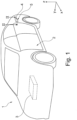
- a vehicle 1 is shown with a vehicle body 2 and a drive unit 3, wherein the drive unit 3 can comprise at least one internal combustion engine, at least one electric machine or a combination of at least one internal combustion engine and at least one electric machine.
- the drive unit 3 can comprise at least one internal combustion engine, at least one electric machine or a combination of at least one internal combustion engine and at least one electric machine.
- the vehicle 1 has a flap 4 at the rear, which is provided for closing and releasing an opening 5 in the vehicle body 2 .
- the opening 5 is provided on a so-called charging trough, with an electrical plug system being able to be brought into operative connection with a corresponding coupling element, which is arranged inside the vehicle body or below the outer skin of the vehicle 1, through the opening 5 in order to to charge electrical energy storage of the vehicle 1.
- the flap 4 thus represents a so-called loading flap here, which is essentially designed as a flat or plate-like element.
- the flap can also serve as a so-called linkage flap of a convertible vehicle, which allows the passage of a top linkage through a body section.
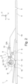
- FIGS. 2 and 3 each show a longitudinal sectional view of a region of the vehicle 1 along a 1 more specifically marked section line II-II, in which the flap 4 is arranged. while showing 2 the flap 4 in an operating state in which the flap 4 completely closes the opening 5 of the vehicle body 2 .
- a side surface 16 of the flap 4 is flush with an outer side 17 of the vehicle body 2 when the flap 4 is in the closed position.
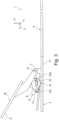
- the flap is 4 in 3 shown in an operating state in which the flap 4 is lowered or displaced under an adjacent area of the vehicle body 2 and the opening 5 releases substantially completely.
- a multi-joint mechanism designed here as a four-joint mechanism 6 is provided for pivoting the flap 4 under the adjacent area of the vehicle body 2 .
- the flap 4 can be adjusted via the four-bar mechanism 6 between the open position, in which the opening 5 of the vehicle body 2 is uncovered by the flap 4, and the closed position of the flap 4, in which the opening 5 is closed by the flap 4.
- the flap 4 is pivoted in its open position relative to the closed position about the axis of rotation 7 of the first pivot joint 8 into the interior of the vehicle body 2 .
- the flap 4 is designed to be rotatable about an axis of rotation 7 of a first rotary joint 8 fixed on the bodywork.
- a lever 9 of the four-bar mechanism 6 is rotatably connected to the flap 4 via a second rotary joint 10 .
- the lever 9 is rotatably connected to a rotary element 12 via a third rotary joint 11 .
- the rotary element 12 is designed to be rotatable about an axis of rotation 13 of a fourth rotary joint 14 that is fixed on the vehicle body.
- the rotary element 12 is acted upon by a spring device 15 with a spring force acting in the direction of a rotary position of the rotary element 12 .
- the spring device 15 attempts to move the rotary element 12 into a rotary position that the rotary element 12 assumes when the flap 4 is in the open position.
- a Bowden cable 18 acts on the outer circumference of the rotating element 12 , via which a positioning force or actuating force can be applied to the rotating element 12 , which counteracts the spring force of the torsion spring or the spring device 15 .
- the rotary element 12 is designed as a roller on which a partial area of the Bowden cable can be rolled up or unwound depending on the respective direction of rotation of the rotary element 12 .
- the first pivot joint 8 is arranged in the longitudinal direction X of the vehicle 1 between the second pivot joint 10 and the fourth pivot joint 14 .
- the third pivot joint 11 is positioned in the closed position of the flap 4 in the longitudinal direction of the vehicle 1 between the first pivot joint 8 and the fourth pivot joint 14 .
- the first pivot joint 8 is arranged in the longitudinal direction X between the second pivot joint 10 and the third pivot joint 11 when the flap 4 is in the closed position.
- the lever 9 and the rotary element 12 are at least approximately in an extended position in which the axes of rotation 10A, 11A, 13 of the second rotary joint 10, the third rotary joint 11 and the fourth rotary joint 14 lie on a straight line G .
- the axis of rotation 11A of the third pivot 11 in relation to the axes of rotation 7, 10A and 13 of the first pivot 8, the second pivot 10 and the fourth pivot 14 has an over-center position.
- This has the effect that actuating forces that act on the four-bar mechanism result from actuating forces that act on the flap 4 in the closing direction.
- the actuating forces each act on the rotary element 12 in a direction of rotation by which the rotary element 12 is transferred into a rotary position which the rotary element 12 has in the open position of the flap 4 .
- an actuator (not shown in the drawing) is actuated and the holding force applied by the Bowden cable 18 to the rotary element 12 is reduced such that the spring device 15 rotates the rotary element 12 about the axis of rotation 13 of the fourth rotary joint 14 .
- the axis of rotation 11A of the third rotary joint 11 is thereby derived from the in 2 position shown in the in 3 position shown pivoted.
- part of the Bowden cable 18 is wound up on the circumference of the rotary element 12 and the flap 4 is pivoted about the axis of rotation 7 of the first rotary joint 8 from its closed position into its open position.
- the flap 4 is to be transferred from its open position to its closed position as required, a corresponding force is applied to the rotary element 12 by means of the Bowden cable 18, which causes the rotary element 12 to rotate about the axis of rotation 13 of the fourth rotary joint 14.
- the third rotary joint 11 is pivoted or rotated together with the rotary element 12 . This results in the lever 9 pivoting the flap 4 about the axis of rotation 7 of the first pivot joint 8 and moving the flap 4 into its position closing the opening 5 .
Landscapes
- Engineering & Computer Science (AREA)
- Mechanical Engineering (AREA)
- Life Sciences & Earth Sciences (AREA)
- Sustainable Development (AREA)
- Sustainable Energy (AREA)
- Chemical & Material Sciences (AREA)
- Combustion & Propulsion (AREA)
- Transportation (AREA)
- Superstructure Of Vehicle (AREA)
- Lock And Its Accessories (AREA)
- Power-Operated Mechanisms For Wings (AREA)
Abstract
Es wird ein Fahrzeug (1) mit einer bewegbaren Klappe (4) beschrieben, die über einen Mehrgelenk-Mechanismus (6) zwischen einer Offenstellung, in der eine Öffnung (5) einer Fahrzeugkarosserie (2) von der Klappe (4) freigegeben ist, und einer Schließstellung, in der die Öffnung (5) von der Klappe (4) verschlossen ist, verstellbar ist. Die Klappe (4) ist um eine karosserieseitig festgelegte Drehachse (7) eines ersten Drehgelenks (8) drehbar ausgeführt. Ein Hebel (9) des Mehrgelenk-Mechanismus (6) steht über ein zweites Drehgelenk (10) drehbar mit der Klappe (4) in Verbindung. Der Hebel (9) ist zusätzlich über ein drittes Drehgelenk (11) mit einem Drehelement (12) drehbar verbunden, das um eine karosserieseitig festgelegte Drehachse (13) eines vierten Drehgelenks (14) drehbar ausgeführt ist. Das Drehelement (12) ist von einer Federeinrichtung (15) mit einer in Richtung einer Drehstellung des Drehelementes (12) wirkenden Federkraft beaufschlagt, die das Drehelement (12) in der Offenstellung oder in der Schließstellung einnimmt. Am Drehelement (12) ist über einen Bowdenzug (18) jeweils eine der Federkraft der Federeinrichtung (15) entgegenwirkende Betätigungskraft anlegbar.A vehicle (1) with a movable flap (4) is described which, via a multi-joint mechanism (6), can be moved between an open position, in which an opening (5) in a vehicle body (2) is released by the flap (4), and a closed position in which the opening (5) is closed by the flap (4). The flap (4) is designed to be rotatable about an axis of rotation (7) of a first rotary joint (8) fixed on the bodywork. A lever (9) of the multi-joint mechanism (6) is rotatably connected to the flap (4) via a second pivot joint (10). The lever (9) is additionally rotatably connected via a third pivot (11) to a rotary element (12) which is designed to be rotatable about an axis of rotation (13) of a fourth pivot (14) fixed on the bodywork. The rotary element (12) is acted upon by a spring device (15) with a spring force acting in the direction of a rotary position of the rotary element (12), which spring force assumes the rotary element (12) in the open position or in the closed position. An actuating force counteracting the spring force of the spring device (15) can be applied to the rotary element (12) via a Bowden cable (18).
Description
Die erfindungsgemäße Technologie betrifft ein Fahrzeug mit einer bewegbaren Klappe zur Abdeckung einer Öffnung einer Fahrzeugkarosserie nach der im Oberbegriff des Patentanspruches 1 näher definierten Art.The technology according to the invention relates to a vehicle with a movable flap for covering an opening of a vehicle body according to the type defined in more detail in the preamble of patent claim 1.
Aus der
Des Weiteren ist in der
Zur Betätigung der vorstehend näher beschriebenen Mechanismen sind unerwünscht hohe Systemkräfte erforderlich. Zusätzlich sind die Mechanismen in ihren Endlagen jeweils nur in unzureichender Art und Weise gegen unerwünschte Stellbewegungen gesichert.Undesirably high system forces are required to actuate the mechanisms described in more detail above. In addition, the mechanisms in their end positions are only insufficiently secured against undesired adjustment movements.
Es ist eine bevorzugte Aufgabe der erfindungsgemäßen Technologie, zumindest einen Nachteil des bekannten Standes der Technik zu verringern oder zu beheben oder eine alternative Lösung vorzuschlagen. Es ist insbesondere eine bevorzugte Aufgabe der hier offenbarten Technologie, ein Fahrzeug mit einer bewegbaren Klappe bereitzustellen, das hinsichtlich mindestens eines der folgenden Faktoren verbessert ist: Herstellungskosten, Komplexität der Herstellung, Bauraumausnutzung, Betriebssicherheit, Nachhaltigkeit und/oder Bauteilzuverlässigkeit.It is a preferred object of the technology according to the invention to reduce or obviate at least one disadvantage of the known art or to propose an alternative solution. In particular, it is a preferred object of the technology disclosed herein to provide a vehicle with a moveable door that is improved in at least one of the following factors: manufacturing cost, manufacturing complexity, space utilization, operational safety, sustainability, and/or component reliability.
Eine besonders bevorzugte Aufgabe wird darin gesehen, die Klappe mit möglichst geringen Systemkräften zu betätigen und in ihren Endlagen auf konstruktiv einfache Art und Weise gegen unerwünschte Stellbewegungen abzusichern.A particularly preferred task is to actuate the flap with the lowest possible system forces and to secure it against undesired adjustment movements in its end positions in a structurally simple manner.
Diese Aufgabe(n) wird/werden mit einem Fahrzeug mit einer bewegbaren Klappe mit den Merkmalen des Patentanspruches 1 gelöst. Vorteilhafte Weiterbildungen sind Gegenstand der Unteransprüche sowie der nachfolgenden Beschreibung entnehmbar.This object(s) is/are achieved with a vehicle having a movable flap with the features of patent claim 1. Advantageous developments can be found in the dependent claims and in the following description.
Es wird ein Fahrzeug mit einer bewegbaren Klappe vorgeschlagen. Die Klappe ist über einen Mehrgelenk-Mechanismus zwischen einer Offenstellung, in der eine Öffnung einer Fahrzeugkarosserie von der Klappe freigegeben ist, und einer Schließstellung verstellbar, in der die Öffnung von der Klappe geschlossen ist. Die Klappe ist um eine karosserieseitig festgelegte Drehachse eines ersten Drehgelenks drehbar ausgeführt. Ein Hebel des Mehrgelenk-Mechanismus steht über ein zweites Drehgelenk drehbar mit der Klappe in Verbindung. Der Hebel ist zusätzlich über ein drittes Drehgelenk mit einem Drehelement drehbar verbunden, das um eine karosserieseitig festgelegte Drehachse eines vierten Drehgelenks drehbar ausgeführt ist.A vehicle with a movable flap is proposed. The flap is adjustable via a multi-link mechanism between an open position in which an opening of a vehicle body is uncovered by the flap and a closed position in which the opening is closed by the flap. The flap is about a body side fixed axis of rotation of a first Swivel joint designed to be rotatable. A lever of the multi-bar mechanism is pivotally connected to the door via a second pivot. The lever is additionally rotatably connected via a third pivot joint to a pivot element which is designed to be rotatable about an axis of rotation of a fourth pivot joint fixed on the bodywork.
Erfindungsgemäß ist das Drehelement von einer Federeinrichtung mit einer in Richtung einer Drehstellung des Drehelementes wirkenden Federkraft beaufschlagt, wobei das Drehelement die Drehstellung je nach Ausführung des Fahrzeuges in der Offenstellung oder in der Schließstellung einnimmt. Zusätzlich ist am Drehelement über einen Bowdenzug jeweils eine der Federkraft der Drehfeder entgegenwirkende Betätigungskraft anlegbar.According to the invention, the rotary element is acted upon by a spring device with a spring force acting in the direction of a rotary position of the rotary element, with the rotary element assuming the rotary position in the open position or in the closed position depending on the design of the vehicle. In addition, an actuating force counteracting the spring force of the torsion spring can be applied to the rotating element via a Bowden cable.
Damit ist die Klappe durch die Federeinrichtung in seine Offenstellung oder in seine Schließstellung überführbar und zusätzlich auch in der Schließ- oder Offenstellung auf konstruktiv einfache Art und Weise haltbar. Zusätzlich ist die Klappe mittels des Bowdenzugs und entgegen der Federkraft der Federeinrichtung in seine Schließ- oder seine Offenstellung überführbar und von diesem in der Schließ- oder Offenstellung in gewünschter Art und Weise haltbar sowie gegen unerwünschte Stellbewegungen in der Schließ- oder Offenstellung haltbar bzw. gesichert.The flap can thus be transferred into its open position or into its closed position by the spring device and can also be held in the closed or open position in a structurally simple manner. In addition, the flap can be moved into its closed or open position by means of the Bowden cable and against the spring force of the spring device and can be held in the closed or open position in the desired manner and held or secured against unwanted adjustment movements in the closed or open position .
In einer bevorzugten einfachen Ausführung ist der Mehrgelenk-Mechanismus als Viergelenk-Mechanismus ausgebildet, jedoch kann er je nach Anwendungsfall z. B. auch als Siebengelenk-Mechanismus oder mit einer anderen Anzahl an Gelenken ausgeführt sein.In a preferred simple embodiment, the multi-bar mechanism is designed as a four-bar mechanism, but it can, depending on the application, for. B. also be designed as a seven-bar mechanism or with a different number of joints.
Bei einer konstruktiv einfachen und bauraumgünstigen Ausführungsform ist das Drehelement als Rolle ausgeführt, auf dem der Bowdenzug während einer Betätigung der Klappe auf- und abwickelbar ist.In a structurally simple and space-saving embodiment, the rotary element is designed as a roller on which the Bowden cable can be wound and unwound during actuation of the flap.
Bei einer vorteilhaften Ausführungsform des erfindungsgemäßen Fahrzeugs ist das dritte Drehgelenk in der Schließstellung der Klappe in Längsrichtung zwischen dem zweiten Drehgelenk und dem vierten Drehgelenk angeordnet. Die Klappe ist dann mit geringen Systemkräften in der Schließstellung durch die Federeinrichtung oder den Bowdenzug haltbar. Dies ist der Fall, da dann auf einfache Art und Weise eine sogenannte Streckstellung des Viergelenk-Mechanismus realisierbar ist.In an advantageous embodiment of the vehicle according to the invention, the third pivot is arranged in the closed position of the flap in the longitudinal direction between the second pivot and the fourth pivot. The flap can then be held in the closed position with low system forces by the spring device or the Bowden cable. This is the case because a so-called extended position of the four-bar mechanism can then be realized in a simple manner.
Bei einer weiteren Ausführungsform des erfindungsgemäßen Fahrzeugs kann das erste Drehgelenk in der Schließstellung der Klappe in Längsrichtung zwischen dem zweiten Drehgelenk und dem vierten Drehgelenk angeordnet sein.In a further embodiment of the vehicle according to the invention, the first pivot can be arranged in the closed position of the flap in the longitudinal direction between the second pivot and the fourth pivot.
Ist das dritte Drehgelenk in der Schließstellung der Klappe zwischen dem ersten Drehgelenk und dem vierten Drehgelenk positioniert, ist die Klappe wiederum mit geringen Systemkräften in der Schließstellung haltbar.If the third pivot joint is positioned between the first pivot joint and the fourth pivot joint when the flap is in the closed position, the flap can again be held in the closed position with low system forces.
Zusätzlich kann es vorgesehen sein, dass das erste Drehgelenk in der Schließstellung der Klappe in Längsrichtung zwischen dem zweiten Drehgelenk und dem dritten Drehgelenk angeordnet ist. Diese Anordnung der Drehgelenke zueinander begünstigt wiederum die Möglichkeit, die Klappe mit geringen Systemkräften in ihrer Schließstellung zu halten.In addition, provision can be made for the first pivot joint to be arranged in the longitudinal direction between the second pivot joint and the third pivot joint when the flap is in the closed position. This arrangement of the rotary joints in relation to one another in turn favors the possibility of holding the flap in its closed position with low system forces.
Der Hebel und das Drehelement können in der Schließstellung der Klappe wenigstens annähernd in einer Strecklage vorliegen, in der die Drehachsen des zweiten Drehgelenks, des dritten Drehgelenks und des vierten Drehgelenks auf einer Geraden liegen. Dann ist die Klappe mit besonders geringen Systemkräften in ihrer Schließstellung haltbar.In the closed position of the flap, the lever and the rotating element can be at least approximately in an extended position in which the axes of rotation of the second rotating joint, the third rotating joint and the fourth rotating joint lie on a straight line. The flap can then be held in its closed position with particularly low system forces.
Die Drehachse des dritten Drehgelenks kann in der Offenstellung der Klappe in Bezug auf die Drehachsen des ersten Drehgelenks, des zweiten Drehgelenks und des vierten Drehgelenks eine Übertotpunktlage aufweisen. Dann resultieren auf konstruktiv einfache Art und Weise aus Stellkräften, die an der Klappe anliegen und die an der Klappe in Richtung ihrer Schließstellung oder ihrer Offenstellung angreifen, jeweils das Drehelement in Richtung der Drehstellung, die das Drehelement in der Offenstellung der Klappe aufweist, betätigende Stellkräfte.In the open position of the flap, the pivot axis of the third pivot joint can have an over-center position in relation to the pivot axes of the first pivot joint, the second pivot joint and the fourth pivot joint. Then result in a structurally simple way from actuating forces at the Abutting the flap and attacking the flap in the direction of its closed position or its open position, in each case the rotary element in the direction of the rotary position, which has the rotary element in the open position of the flap, actuating forces.
Die Klappe kann in ihrer Offenstellung gegenüber der Schließstellung um die Drehachse des ersten Drehgelenks in das Innere der Fahrzeugkarosserie verschwenkbar sein. Dadurch ist die Klappe in der Offenstellung durch die Fahrzeugkarosserie gegen Beschädigungen geschützt.In its open position relative to the closed position, the flap can be pivotable about the axis of rotation of the first pivot joint into the interior of the vehicle body. As a result, the flap is protected against damage by the vehicle body in the open position.
Bei einer konstruktiv einfachen und mit geringem Aufwand montierbaren Ausführungsform des erfindungsgemäßen Fahrzeuges ist die Federeinrichtung als Schenkelfeder ausgeführt.In a structurally simple embodiment of the vehicle according to the invention that can be assembled with little effort, the spring device is designed as a torsion spring.
Die Erfindung ist nicht auf die angegebene Kombination der Merkmale der unabhängigen Ansprüche oder der hiervon abhängigen Ansprüche beschränkt. Es ergeben sich darüber hinaus Möglichkeiten, einzelne Merkmale auch soweit sie aus den Ansprüchen, der nachfolgenden Beschreibung von Ausführungsformen oder unmittelbar aus der Zeichnung hervorgehen, miteinander zu kombinieren. Die Bezugnahme der Ansprüche auf die Zeichnungen durch Verwendung von Bezugszeichen soll den Schutzumfang der Ansprüche nicht beschränken.The invention is not limited to the specified combination of the features of the independent claims or the claims dependent thereon. In addition, there are possibilities of combining individual features with one another, even if they emerge from the claims, the following description of embodiments or directly from the drawing. Reference of the claims to the drawings by the use of reference signs is not intended to limit the scope of the claims.
Die vorgeschlagene bewegbare Klappe eignet sich prinzipiell zur Abdeckung jeder Karosserieöffnung, abgesehen von Fahrzeugtüröffnungen und anderen Öffnungen derartiger Dimension. Insbesondere eignet sich die bewegbare Klappe als Tankdeckel zur Abdeckung einer Tankmulde oder als Ladedeckel einer Lademulde eines Fahrzeugs mit elektrischem Antrieb. Bei einem Cabriolet-Fahrzeug kann eine derartige Klappe als sogenannte Gestängeaustrittsklappe zur Abdeckung einer Karosserieöffnung, durch welche Gestängeteile eines Verdeckgestänges bei einer Verdeckbewegung geführt werden, dienen.The proposed moveable flap is in principle suitable for covering any body opening, apart from vehicle door openings and other openings of such dimensions. In particular, the movable flap is suitable as a tank cover for covering a fuel tank recess or as a charging cover for a charging recess of a vehicle with an electric drive. In a convertible vehicle, such a flap can serve as a so-called linkage exit flap for covering a body opening through which linkage parts of a top linkage are guided when the top is moved.
Die hier offenbarte Technologie wird nun anhand der Figuren der Zeichnung näher erläutert, wobei die Figuren wie auch die nachfolgende Beschreibung nur zu illustrativen Zwecken und nicht zum Zweck der Beschränkung der Erfindung dienen.The technology disclosed here will now be explained in more detail with reference to the figures of the drawing, the figures as well as the following Description is for illustrative purposes only and not for the purpose of limiting the invention.
Es zeigt:
- Fig. 1
- eine schematische Seitenansicht eines Fahrzeuges mit einer Klappe, die eine Öffnung der Fahrzeugkarosserie verschließt;
- Fig. 2
- eine zweidimensionale Schnittansicht entlang einer in
Fig. 1 näher gekennzeichneten Schnittlinie II-II bei durch die Klappe geschlossener Öffnung; und - Fig. 3
- eine
Fig. 2 entsprechende Darstellung, wobei die Klappe die Öffnung freigibt.
- 1
- a schematic side view of a vehicle with a flap that closes an opening of the vehicle body;
- 2
- a two-dimensional sectional view along an in
1 Section line II-II marked in more detail when the opening is closed by the flap; and - 3
- one
2 corresponding representation, with the flap releasing the opening.
Bezug nehmend auf
Vorliegend weist das Fahrzeug 1 heckseitig eine Klappe 4 auf, die zum Verschließen und Freigeben einer Öffnung 5 in der Fahrzeugkarosserie 2 vorgesehen ist. Die Öffnung 5 ist bei der gezeigten Ausführung an einer so genannten Lademulde vorgesehen, wobei durch die Öffnung 5 ein elektrisches Steckersystem mit einem entsprechenden Koppelelement, das innerhalb der Fahrzeugkarosserie bzw. unterhalb der Außenhaut des Fahrzeuges 1 angeordnet ist, in Wirkverbindung bringbar ist, um einen elektrischen Energiespeicher des Fahrzeuges 1 aufladen zu können. Die Klappe 4 stellt hier somit eine sogenannte Ladeklappe dar, die im Wesentlichen als ein ebenes bzw. plattenartiges Element ausgeführt ist.In the present case, the vehicle 1 has a
In der gezeigten Ausführung kann die Klappe jedoch auch als sogenannte Gestängeklappe eines Cabriolet-Fahrzeugs, welche den Durchtritt eines Verdeckgestänges durch einen Karosserieabschnitt erlaubt, dienen.In the embodiment shown, however, the flap can also serve as a so-called linkage flap of a convertible vehicle, which allows the passage of a top linkage through a body section.
Zum Verschwenken der Klappe 4 unter den angrenzenden Bereich der Fahrzeugkarosserie 2 ist ein hier als Viergelenk-Mechanismus 6 ausgebildeter Mehrgelenk-Mechanismus vorgesehen. Die Klappe 4 ist über den Viergelenk-Mechanismus 6 zwischen der Offenstellung, in der die Öffnung 5 der Fahrzeugkarosserie 2 von der Klappe 4 freigegeben ist, und der Schließstellung der Klappe 4 verstellbar, in der die Öffnung 5 von der Klappe 4 verschlossen ist. Dabei ist die Klappe 4 in ihrer Offenstellung gegenüber der Schließstellung um die Drehachse 7 des ersten Drehgelenks 8 in das Innere der Fahrzeugkarosserie 2 verschwenkt.A multi-joint mechanism designed here as a four-joint mechanism 6 is provided for pivoting the
Dabei ist die Klappe 4 um eine karosserieseitig festgelegte Drehachse 7 eines ersten Drehgelenkes 8 drehbar ausgeführt. Ein Hebel 9 des Viergelenk-Mechanismus 6 steht über ein zweites Drehgelenk 10 drehbar mit der Klappe 4 in Verbindung. Zusätzlich ist der Hebel 9 über ein drittes Drehgelenk 11 mit einem Drehelement 12 drehbar verbunden. Das Drehelement 12 ist um eine karosserieseitig festgelegte Drehachse 13 eines vierten Drehgelenks 14 drehbar ausgeführt.In this case, the
Des Weiteren ist das Drehelement 12 von einer Federeinrichtung 15 mit einer in Richtung einer Drehstellung des Drehelementes 12 wirkenden Federkraft beaufschlagt. Die Federeinrichtung 15 versucht dabei, das Drehelement 12 in eine Drehstellung zu überführen, die das Drehelement 12 in der Offenstellung der Klappe 4 einnimmt. Zusätzlich greift am äußeren Umfang des Drehelementes 12 ein Bowdenzug 18 an, über den am Drehelement 12 eine Stellkraft bzw. Betätigungskraft anlegbar ist, die der Federkraft der Drehfeder bzw. der Federeinrichtung 15 entgegenwirkt.Furthermore, the
Das Drehelement 12 ist als Rolle ausgeführt, auf der ein Teilbereich des Bowdenzuges in Abhängigkeit der jeweiligen Drehrichtung des Drehelementes 12 aufrollbar oder von dieser abwickelbar ist.The
In der in
Damit liegen der Hebel 9 und das Drehelement 12 in der Schließstellung der Klappe 4 wenigstens annähernd in einer Strecklage vor, in der die Drehachsen 10A, 11A, 13 des zweiten Drehgelenks 10, des dritten Drehgelenks 11 und des vierten Drehgelenks 14 auf einer Geraden G liegen. Dadurch wird verhindert, dass an der Klappe 4 in Fahrzeugquerrichtung Y angreifende Betätigungskräfte ein unerwünschtes Öffnen bzw. Freigeben der Öffnung 5 ermöglichen. Aufgrund der Strecklage des Hebels 9 und des Drehelementes 12 ist die Klappe 4 mit geringen Systemkräften bzw. Federkräften der Federeinrichtung 15 in seiner Schließstellung haltbar.Thus, in the closed position of the
In der Offenstellung der Klappe 4 weist die Drehachse 11A des dritten Drehgelenkes 11 in Bezug auf die Drehachsen 7, 10A und 13 des ersten Drehgelenks 8, des zweiten Drehgelenks 10 und des vierten Drehgelenks 14 eine Übertotpunktlage auf. Dies bewirkt, dass aus Stellkräften, die an der Klappe 4 in Schließrichtung angreifen, jeweils am Viergelenk-Mechanismus angreifende Betätigungskräfte resultieren. Die Betätigungskräfte greifen dabei jeweils am Drehelement 12 in eine Drehrichtung an, durch die das Drehelement 12 in eine Drehstellung überführt wird, die das Drehelement 12 in der Offenstellung der Klappe 4 aufweist.In the open position of the
Liegt eine entsprechende Anforderung zum Freigeben der Öffnung 5 vor, wird ein in der Zeichnung nicht näher dargestellter Aktuator betätigt und die vom Bowdenzug 18 am Drehelement 12 anliegende Haltekraft dahingehend reduziert, dass die Federeinrichtung 15 das Drehelement 12 um die Drehachse 13 des vierten Drehgelenkes 14 verdreht. Die Drehachse 11A des dritten Drehgelenkes 11 wird dabei aus der in
Soll die Klappe 4 anforderungsgemäß aus ihrer Offenstellung in ihre Schließstellung überführt werden, wird mittels des Bowdenzuges 18 am Drehelement 12 eine entsprechende Kraft angelegt, die eine Rotation des Drehelementes 12 um die Drehachse 13 des vierten Drehgelenkes 14 zur Folge hat. Während dieser Drehbewegung des Drehelementes 12 um die Drehachse 13 wird das dritte Drehgelenk 11 gemeinsam mit dem Drehelement 12 verschwenkt bzw. verdreht. Dies führt dazu, dass der Hebel 9 die Klappe 4 um die Drehachse 7 des ersten Drehgelenkes 8 verschwenkt und die Klappe 4 in ihre die Öffnung 5 verschließende Position überführt.If the
- 11
- Fahrzeugvehicle
- 22
- Fahrzeugkarosserievehicle body
- 33
- Antriebseinheitdrive unit
- 44
- Klappeflap
- 55
- Öffnungopening
- 66
- Mehrgelenk-Mechanismusmulti-joint mechanism
- 77
- Drehachseaxis of rotation
- 88th
- erstes Drehgelenkfirst pivot
- 99
- Hebellever
- 1010
- zweites Drehgelenksecond pivot
- 10A10A
- Drehachse des zweiten DrehgelenksAxis of rotation of the second pivot joint
- 1111
- drittes Drehgelenkthird pivot
- 11A11A
- Drehachse des dritten DrehgelenksAxis of rotation of the third pivot
- 1212
- Drehelementrotary element
- 1313
- Drehachse des vierten DrehgelenksAxis of rotation of the fourth pivot
- 1414
- viertes Drehgelenkfourth pivot
- 1515
- Federeinrichtungspring device
- 1616
- Seitenfläche der Klappeside surface of the flap
- 1717
- Außenseite der Fahrzeugkarosserieexterior of the vehicle body
- 1818
- Bowdenzugbowden cable
- GG
- GeradeStraight
- XX
- Fahrzeuglängsrichtungvehicle longitudinal direction
- YY
- Fahrzeugquerrichtungvehicle transverse direction
Claims (10)
dadurch gekennzeichnet, dass
der Mehrgelenk-Mechanismus (6) als Viergelenk-Mechanismus (6) ausgeführt ist.Vehicle according to claim 1,
characterized in that
the multi-bar mechanism (6) is designed as a four-bar mechanism (6).
dadurch gekennzeichnet, dass
das Drehelement (12) als Rolle ausgeführt ist.Vehicle according to claim 1 or 2,
characterized in that
the rotary element (12) is designed as a roller.
dadurch gekennzeichnet, dass
das erste Drehgelenk (8) in der Schließstellung der Klappe (4) in Längsrichtung (X) zwischen dem zweiten Drehgelenk (10) und dem vierten Drehgelenk (14) angeordnet ist.Vehicle according to claim 1, 2 or 3,
characterized in that
the first pivot (8) is arranged in the closed position of the flap (4) in the longitudinal direction (X) between the second pivot (10) and the fourth pivot (14).
dadurch gekennzeichnet, dass
das dritte Drehgelenk (11) in der Schließstellung der Klappe (4) in Längsrichtung (X) zwischen dem ersten Drehgelenk (8) und dem vierten Drehgelenk (14) positioniert ist.Vehicle according to at least one of the preceding claims,
characterized in that
the third pivot (11) is positioned in the closed position of the flap (4) in the longitudinal direction (X) between the first pivot (8) and the fourth pivot (14).
dadurch gekennzeichnet, dass
das erste Drehgelenk (8) in der Schließstellung der Klappe (4) in Längsrichtung (X) zwischen dem zweiten Drehgelenk (10) und dem dritten Drehgelenk (11) angeordnet ist.Vehicle according to at least one of the preceding claims,
characterized in that
the first pivot (8) is arranged in the closed position of the flap (4) in the longitudinal direction (X) between the second pivot (10) and the third pivot (11).
dadurch gekennzeichnet, dass
der Hebel (9) und das Drehelement (12) in der Schließstellung der Klappe (4) wenigstens annähernd in einer Strecklage vorliegen, in der die Drehachsen (10A, 11A, 13) des zweiten Drehgelenks (10), des dritten Drehgelenks (11) und des vierten Drehgelenks (14) auf einer Geraden (G) liegen.Vehicle according to at least one of the preceding claims,
characterized in that
the lever (9) and the rotary element (12) are in the closed position of the flap (4) at least approximately in an extended position in which the axes of rotation (10A, 11A, 13) of the second rotary joint (10), the third rotary joint (11) and the fourth rotary joint (14) lie on a straight line (G).
dadurch gekennzeichnet, dass
die Drehachse (11A) des dritten Drehgelenks (11) in der Offenstellung der Klappe (4) in Bezug auf die Drehachsen (7, 10A, 13) des ersten Drehgelenks (8), des zweiten Drehgelenks (10) und des vierten Drehgelenks (14) eine Übertotpunktlage aufweist, so dass aus an der Klappe (4) anliegenden Stellkräften, die an der Klappe (4) in Richtung ihrer Schließstellung oder ihrer Offenstellung angreifen, jeweils eine das Drehelement (12) in Richtung der Drehstellung, die das Drehelement (12) in der Offenstellung der Klappe (4) aufweist, betätigende Stellkraft resultiert.Vehicle according to at least one of the preceding claims,
characterized in that
the axis of rotation (11A) of the third pivot (11) in the open position of the flap (4) with respect to the axes of rotation (7, 10A, 13) of the first pivot (8), the second pivot (10) and the fourth pivot joint (14) has an over-center position, so that from the actuating forces applied to the flap (4) which act on the flap (4) in the direction of its closed position or its open position, one in each case rotates the rotary element (12) in the direction of the rotary position that Having rotary element (12) in the open position of the flap (4), actuating force results.
dadurch gekennzeichnet, dass
eine Seitenfläche (16) der Klappe (4) in der Schließstellung der Klappe (4) bündig mit einer Außenseite (17) der Fahrzeugkarosserie (2) abschließt.Vehicle according to at least one of the preceding claims,
characterized in that
a side surface (16) of the flap (4) in the closed position of the flap (4) is flush with an outside (17) of the vehicle body (2).
dadurch gekennzeichnet, dass
die Klappe (4) in ihrer Offenstellung gegenüber der Schließstellung um die Drehachse (7) des ersten Drehgelenks (8) in das Innere der Fahrzeugkarosserie (2) verschwenkt ist.Vehicle according to at least one of the preceding claims,
characterized in that
the flap (4) in its open position relative to the closed position is pivoted about the axis of rotation (7) of the first pivot joint (8) into the interior of the vehicle body (2).
Applications Claiming Priority (2)
| Application Number | Priority Date | Filing Date | Title |
|---|---|---|---|
| DE102021134394 | 2021-12-22 | ||
| DE102022105588.4A DE102022105588A1 (en) | 2021-12-22 | 2022-03-09 | VEHICLE WITH A MOVABLE FLAP |
Publications (3)
| Publication Number | Publication Date |
|---|---|
| EP4201724A2 true EP4201724A2 (en) | 2023-06-28 |
| EP4201724A3 EP4201724A3 (en) | 2023-07-05 |
| EP4201724B1 EP4201724B1 (en) | 2024-04-03 |
Family
ID=86498071
Family Applications (1)
| Application Number | Title | Priority Date | Filing Date |
|---|---|---|---|
| EP22215162.3A Active EP4201724B1 (en) | 2021-12-22 | 2022-12-20 | Vehicle with a movable flap |
Country Status (1)
| Country | Link |
|---|---|
| EP (1) | EP4201724B1 (en) |
Citations (2)
| Publication number | Priority date | Publication date | Assignee | Title |
|---|---|---|---|---|
| DE102006055268A1 (en) | 2006-11-23 | 2008-06-12 | Wilhelm Karmann Gmbh | Cabriolet vehicle, has convertible top concealed in convertible top storage area and covering flap is arranged in opening position based on vehicle longitudinal direction in area before cabriolet top linkage parts of open convertible top |
| DE102007013517A1 (en) | 2007-03-21 | 2008-09-25 | Wilhelm Karmann Gmbh | Actuating device for use in linkage cover of cabriolet vehicle, has rotatable disk including pivot point with path curve defining path, where lining unit is closed along path and maximally opened or closed at end of path |
Family Cites Families (2)
| Publication number | Priority date | Publication date | Assignee | Title |
|---|---|---|---|---|
| FR2871431B1 (en) * | 2004-06-14 | 2006-09-22 | Peugeot Citroen Automobiles Sa | SHUTTER CAP FOR A BODY OF A MOTOR VEHICLE AND A MOTOR VEHICLE COMPRISING SUCH A TRAPPER |
| DE102020109829A1 (en) * | 2020-04-08 | 2021-10-14 | Huf Hülsbeck & Fürst Gmbh & Co. Kg | Tank flap system of a motor vehicle |
-
2022
- 2022-12-20 EP EP22215162.3A patent/EP4201724B1/en active Active
Patent Citations (2)
| Publication number | Priority date | Publication date | Assignee | Title |
|---|---|---|---|---|
| DE102006055268A1 (en) | 2006-11-23 | 2008-06-12 | Wilhelm Karmann Gmbh | Cabriolet vehicle, has convertible top concealed in convertible top storage area and covering flap is arranged in opening position based on vehicle longitudinal direction in area before cabriolet top linkage parts of open convertible top |
| DE102007013517A1 (en) | 2007-03-21 | 2008-09-25 | Wilhelm Karmann Gmbh | Actuating device for use in linkage cover of cabriolet vehicle, has rotatable disk including pivot point with path curve defining path, where lining unit is closed along path and maximally opened or closed at end of path |
Also Published As
| Publication number | Publication date |
|---|---|
| EP4201724B1 (en) | 2024-04-03 |
| EP4201724A3 (en) | 2023-07-05 |
Similar Documents
| Publication | Publication Date | Title |
|---|---|---|
| DE102018128972B4 (en) | Flap with opening mechanism | |
| DE19714105C2 (en) | Convertible vehicle roof | |
| DE102020209607B4 (en) | Closure arrangement for closing a tank trough of a motor vehicle body | |
| DE102007013517B4 (en) | Actuating device for a movable cladding element, in particular linkage flap, and convertible vehicle with such a cladding element or such a linkage flap | |
| EP4201791B1 (en) | Covering device, in particular loading flap device | |
| EP0222160A2 (en) | Operating device for a freight-loading door | |
| EP1247677A1 (en) | Convertible vehicle | |
| EP1987987A2 (en) | Covering system for boot storage in a vehicle | |
| DE102022107707B3 (en) | DRIVE DEVICE FOR A VEHICLE FLAP | |
| EP1506103A1 (en) | Cover device for the vehicle top storage compartment of a convertible vehicle | |
| DE102008057880B4 (en) | Device for adjusting a flap for a motor vehicle | |
| EP4230471A1 (en) | Vehicle, in particular electrically driven vehicle | |
| DE102007015965A1 (en) | Opening and closing mechanism for luggage space flap of motor vehicle body, has four arms connected with each other in articulated manner to form four-joint and lift or drive cylinder for driving four-joint | |
| DE102019002333A1 (en) | Cooling air control system for a motor vehicle | |
| DE102022105588A1 (en) | VEHICLE WITH A MOVABLE FLAP | |
| EP4201724B1 (en) | Vehicle with a movable flap | |
| DE102005042017A1 (en) | Roof construction for motor vehicles | |
| DE102024113858A1 (en) | VEHICLE DOOR HINGE DEVICE | |
| DE19714106C2 (en) | Convertible vehicle roof | |
| DE102004057016B4 (en) | Opening and closing mechanism for opening and closing a cover device of a storage compartment for a vehicle and storage compartment device | |
| DE102023000776B3 (en) | Storage compartment arrangement | |
| EP1848603B1 (en) | Hard top | |
| EP4206016B1 (en) | Charging interface for a vehicle, having a charging socket, a vehicle flap and a drive device | |
| DE102023111170A1 (en) | DRIVE DEVICE OF A VEHICLE DOOR UNIT | |
| DE102020119669B3 (en) | Lid assembly and vehicle |
Legal Events
| Date | Code | Title | Description |
|---|---|---|---|
| PUAI | Public reference made under article 153(3) epc to a published international application that has entered the european phase |
Free format text: ORIGINAL CODE: 0009012 |
|
| STAA | Information on the status of an ep patent application or granted ep patent |
Free format text: STATUS: THE APPLICATION HAS BEEN PUBLISHED |
|
| PUAL | Search report despatched |
Free format text: ORIGINAL CODE: 0009013 |
|
| AK | Designated contracting states |
Kind code of ref document: A2 Designated state(s): AL AT BE BG CH CY CZ DE DK EE ES FI FR GB GR HR HU IE IS IT LI LT LU LV MC ME MK MT NL NO PL PT RO RS SE SI SK SM TR |
|
| AK | Designated contracting states |
Kind code of ref document: A3 Designated state(s): AL AT BE BG CH CY CZ DE DK EE ES FI FR GB GR HR HU IE IS IT LI LT LU LV MC ME MK MT NL NO PL PT RO RS SE SI SK SM TR |
|
| RIC1 | Information provided on ipc code assigned before grant |
Ipc: B60J 7/20 20060101ALI20230526BHEP Ipc: B60K 15/05 20060101AFI20230526BHEP |
|
| STAA | Information on the status of an ep patent application or granted ep patent |
Free format text: STATUS: REQUEST FOR EXAMINATION WAS MADE |
|
| 17P | Request for examination filed |
Effective date: 20230821 |
|
| RBV | Designated contracting states (corrected) |
Designated state(s): AL AT BE BG CH CY CZ DE DK EE ES FI FR GB GR HR HU IE IS IT LI LT LU LV MC ME MK MT NL NO PL PT RO RS SE SI SK SM TR |
|
| GRAP | Despatch of communication of intention to grant a patent |
Free format text: ORIGINAL CODE: EPIDOSNIGR1 |
|
| STAA | Information on the status of an ep patent application or granted ep patent |
Free format text: STATUS: GRANT OF PATENT IS INTENDED |
|
| INTG | Intention to grant announced |
Effective date: 20231102 |
|
| GRAS | Grant fee paid |
Free format text: ORIGINAL CODE: EPIDOSNIGR3 |
|
| GRAA | (expected) grant |
Free format text: ORIGINAL CODE: 0009210 |
|
| STAA | Information on the status of an ep patent application or granted ep patent |
Free format text: STATUS: THE PATENT HAS BEEN GRANTED |
|
| AK | Designated contracting states |
Kind code of ref document: B1 Designated state(s): AL AT BE BG CH CY CZ DE DK EE ES FI FR GB GR HR HU IE IS IT LI LT LU LV MC ME MK MT NL NO PL PT RO RS SE SI SK SM TR |
|
| REG | Reference to a national code |
Ref country code: CH Ref legal event code: EP |
|
| REG | Reference to a national code |
Ref country code: IE Ref legal event code: FG4D Free format text: LANGUAGE OF EP DOCUMENT: GERMAN |
|
| REG | Reference to a national code |
Ref country code: DE Ref legal event code: R096 Ref document number: 502022000705 Country of ref document: DE |
|
| P01 | Opt-out of the competence of the unified patent court (upc) registered |
Effective date: 20240423 |
|
| REG | Reference to a national code |
Ref country code: LT Ref legal event code: MG9D |
|
| REG | Reference to a national code |
Ref country code: NL Ref legal event code: MP Effective date: 20240403 |
|
| PG25 | Lapsed in a contracting state [announced via postgrant information from national office to epo] |
Ref country code: NL Free format text: LAPSE BECAUSE OF FAILURE TO SUBMIT A TRANSLATION OF THE DESCRIPTION OR TO PAY THE FEE WITHIN THE PRESCRIBED TIME-LIMIT Effective date: 20240403 |
|
| PG25 | Lapsed in a contracting state [announced via postgrant information from national office to epo] |
Ref country code: NL Free format text: LAPSE BECAUSE OF FAILURE TO SUBMIT A TRANSLATION OF THE DESCRIPTION OR TO PAY THE FEE WITHIN THE PRESCRIBED TIME-LIMIT Effective date: 20240403 |
|
| PG25 | Lapsed in a contracting state [announced via postgrant information from national office to epo] |
Ref country code: IS Free format text: LAPSE BECAUSE OF FAILURE TO SUBMIT A TRANSLATION OF THE DESCRIPTION OR TO PAY THE FEE WITHIN THE PRESCRIBED TIME-LIMIT Effective date: 20240803 |
|
| PG25 | Lapsed in a contracting state [announced via postgrant information from national office to epo] |
Ref country code: BG Free format text: LAPSE BECAUSE OF FAILURE TO SUBMIT A TRANSLATION OF THE DESCRIPTION OR TO PAY THE FEE WITHIN THE PRESCRIBED TIME-LIMIT Effective date: 20240403 |
|
| PG25 | Lapsed in a contracting state [announced via postgrant information from national office to epo] |
Ref country code: HR Free format text: LAPSE BECAUSE OF FAILURE TO SUBMIT A TRANSLATION OF THE DESCRIPTION OR TO PAY THE FEE WITHIN THE PRESCRIBED TIME-LIMIT Effective date: 20240403 Ref country code: FI Free format text: LAPSE BECAUSE OF FAILURE TO SUBMIT A TRANSLATION OF THE DESCRIPTION OR TO PAY THE FEE WITHIN THE PRESCRIBED TIME-LIMIT Effective date: 20240403 |
|
| PG25 | Lapsed in a contracting state [announced via postgrant information from national office to epo] |
Ref country code: GR Free format text: LAPSE BECAUSE OF FAILURE TO SUBMIT A TRANSLATION OF THE DESCRIPTION OR TO PAY THE FEE WITHIN THE PRESCRIBED TIME-LIMIT Effective date: 20240704 |
|
| PG25 | Lapsed in a contracting state [announced via postgrant information from national office to epo] |
Ref country code: PT Free format text: LAPSE BECAUSE OF FAILURE TO SUBMIT A TRANSLATION OF THE DESCRIPTION OR TO PAY THE FEE WITHIN THE PRESCRIBED TIME-LIMIT Effective date: 20240805 |
|
| PG25 | Lapsed in a contracting state [announced via postgrant information from national office to epo] |
Ref country code: ES Free format text: LAPSE BECAUSE OF FAILURE TO SUBMIT A TRANSLATION OF THE DESCRIPTION OR TO PAY THE FEE WITHIN THE PRESCRIBED TIME-LIMIT Effective date: 20240403 |
|
| PG25 | Lapsed in a contracting state [announced via postgrant information from national office to epo] |
Ref country code: CZ Free format text: LAPSE BECAUSE OF FAILURE TO SUBMIT A TRANSLATION OF THE DESCRIPTION OR TO PAY THE FEE WITHIN THE PRESCRIBED TIME-LIMIT Effective date: 20240403 |
|
| PG25 | Lapsed in a contracting state [announced via postgrant information from national office to epo] |
Ref country code: PL Free format text: LAPSE BECAUSE OF FAILURE TO SUBMIT A TRANSLATION OF THE DESCRIPTION OR TO PAY THE FEE WITHIN THE PRESCRIBED TIME-LIMIT Effective date: 20240403 |
|
| PG25 | Lapsed in a contracting state [announced via postgrant information from national office to epo] |
Ref country code: LV Free format text: LAPSE BECAUSE OF FAILURE TO SUBMIT A TRANSLATION OF THE DESCRIPTION OR TO PAY THE FEE WITHIN THE PRESCRIBED TIME-LIMIT Effective date: 20240403 |
|
| PG25 | Lapsed in a contracting state [announced via postgrant information from national office to epo] |
Ref country code: PT Free format text: LAPSE BECAUSE OF FAILURE TO SUBMIT A TRANSLATION OF THE DESCRIPTION OR TO PAY THE FEE WITHIN THE PRESCRIBED TIME-LIMIT Effective date: 20240805 Ref country code: PL Free format text: LAPSE BECAUSE OF FAILURE TO SUBMIT A TRANSLATION OF THE DESCRIPTION OR TO PAY THE FEE WITHIN THE PRESCRIBED TIME-LIMIT Effective date: 20240403 Ref country code: NO Free format text: LAPSE BECAUSE OF FAILURE TO SUBMIT A TRANSLATION OF THE DESCRIPTION OR TO PAY THE FEE WITHIN THE PRESCRIBED TIME-LIMIT Effective date: 20240703 Ref country code: LV Free format text: LAPSE BECAUSE OF FAILURE TO SUBMIT A TRANSLATION OF THE DESCRIPTION OR TO PAY THE FEE WITHIN THE PRESCRIBED TIME-LIMIT Effective date: 20240403 Ref country code: IS Free format text: LAPSE BECAUSE OF FAILURE TO SUBMIT A TRANSLATION OF THE DESCRIPTION OR TO PAY THE FEE WITHIN THE PRESCRIBED TIME-LIMIT Effective date: 20240803 Ref country code: HR Free format text: LAPSE BECAUSE OF FAILURE TO SUBMIT A TRANSLATION OF THE DESCRIPTION OR TO PAY THE FEE WITHIN THE PRESCRIBED TIME-LIMIT Effective date: 20240403 Ref country code: GR Free format text: LAPSE BECAUSE OF FAILURE TO SUBMIT A TRANSLATION OF THE DESCRIPTION OR TO PAY THE FEE WITHIN THE PRESCRIBED TIME-LIMIT Effective date: 20240704 Ref country code: FI Free format text: LAPSE BECAUSE OF FAILURE TO SUBMIT A TRANSLATION OF THE DESCRIPTION OR TO PAY THE FEE WITHIN THE PRESCRIBED TIME-LIMIT Effective date: 20240403 Ref country code: ES Free format text: LAPSE BECAUSE OF FAILURE TO SUBMIT A TRANSLATION OF THE DESCRIPTION OR TO PAY THE FEE WITHIN THE PRESCRIBED TIME-LIMIT Effective date: 20240403 Ref country code: CZ Free format text: LAPSE BECAUSE OF FAILURE TO SUBMIT A TRANSLATION OF THE DESCRIPTION OR TO PAY THE FEE WITHIN THE PRESCRIBED TIME-LIMIT Effective date: 20240403 Ref country code: BG Free format text: LAPSE BECAUSE OF FAILURE TO SUBMIT A TRANSLATION OF THE DESCRIPTION OR TO PAY THE FEE WITHIN THE PRESCRIBED TIME-LIMIT Effective date: 20240403 Ref country code: RS Free format text: LAPSE BECAUSE OF FAILURE TO SUBMIT A TRANSLATION OF THE DESCRIPTION OR TO PAY THE FEE WITHIN THE PRESCRIBED TIME-LIMIT Effective date: 20240703 |
|
| REG | Reference to a national code |
Ref country code: DE Ref legal event code: R097 Ref document number: 502022000705 Country of ref document: DE |
|
| PG25 | Lapsed in a contracting state [announced via postgrant information from national office to epo] |
Ref country code: DK Free format text: LAPSE BECAUSE OF FAILURE TO SUBMIT A TRANSLATION OF THE DESCRIPTION OR TO PAY THE FEE WITHIN THE PRESCRIBED TIME-LIMIT Effective date: 20240403 |
|
| PG25 | Lapsed in a contracting state [announced via postgrant information from national office to epo] |
Ref country code: EE Free format text: LAPSE BECAUSE OF FAILURE TO SUBMIT A TRANSLATION OF THE DESCRIPTION OR TO PAY THE FEE WITHIN THE PRESCRIBED TIME-LIMIT Effective date: 20240403 |
|
| PG25 | Lapsed in a contracting state [announced via postgrant information from national office to epo] |
Ref country code: SK Free format text: LAPSE BECAUSE OF FAILURE TO SUBMIT A TRANSLATION OF THE DESCRIPTION OR TO PAY THE FEE WITHIN THE PRESCRIBED TIME-LIMIT Effective date: 20240403 Ref country code: RO Free format text: LAPSE BECAUSE OF FAILURE TO SUBMIT A TRANSLATION OF THE DESCRIPTION OR TO PAY THE FEE WITHIN THE PRESCRIBED TIME-LIMIT Effective date: 20240403 |
|
| PG25 | Lapsed in a contracting state [announced via postgrant information from national office to epo] |
Ref country code: SM Free format text: LAPSE BECAUSE OF FAILURE TO SUBMIT A TRANSLATION OF THE DESCRIPTION OR TO PAY THE FEE WITHIN THE PRESCRIBED TIME-LIMIT Effective date: 20240403 |
|
| PG25 | Lapsed in a contracting state [announced via postgrant information from national office to epo] |
Ref country code: SM Free format text: LAPSE BECAUSE OF FAILURE TO SUBMIT A TRANSLATION OF THE DESCRIPTION OR TO PAY THE FEE WITHIN THE PRESCRIBED TIME-LIMIT Effective date: 20240403 Ref country code: SK Free format text: LAPSE BECAUSE OF FAILURE TO SUBMIT A TRANSLATION OF THE DESCRIPTION OR TO PAY THE FEE WITHIN THE PRESCRIBED TIME-LIMIT Effective date: 20240403 Ref country code: RO Free format text: LAPSE BECAUSE OF FAILURE TO SUBMIT A TRANSLATION OF THE DESCRIPTION OR TO PAY THE FEE WITHIN THE PRESCRIBED TIME-LIMIT Effective date: 20240403 Ref country code: EE Free format text: LAPSE BECAUSE OF FAILURE TO SUBMIT A TRANSLATION OF THE DESCRIPTION OR TO PAY THE FEE WITHIN THE PRESCRIBED TIME-LIMIT Effective date: 20240403 Ref country code: DK Free format text: LAPSE BECAUSE OF FAILURE TO SUBMIT A TRANSLATION OF THE DESCRIPTION OR TO PAY THE FEE WITHIN THE PRESCRIBED TIME-LIMIT Effective date: 20240403 |
|
| PLBE | No opposition filed within time limit |
Free format text: ORIGINAL CODE: 0009261 |
|
| STAA | Information on the status of an ep patent application or granted ep patent |
Free format text: STATUS: NO OPPOSITION FILED WITHIN TIME LIMIT |
|
| 26N | No opposition filed |
Effective date: 20250106 |
|
| PG25 | Lapsed in a contracting state [announced via postgrant information from national office to epo] |
Ref country code: SI Free format text: LAPSE BECAUSE OF FAILURE TO SUBMIT A TRANSLATION OF THE DESCRIPTION OR TO PAY THE FEE WITHIN THE PRESCRIBED TIME-LIMIT Effective date: 20240403 |
|
| PG25 | Lapsed in a contracting state [announced via postgrant information from national office to epo] |
Ref country code: MC Free format text: LAPSE BECAUSE OF FAILURE TO SUBMIT A TRANSLATION OF THE DESCRIPTION OR TO PAY THE FEE WITHIN THE PRESCRIBED TIME-LIMIT Effective date: 20240403 |
|
| REG | Reference to a national code |
Ref country code: DE Ref legal event code: R081 Ref document number: 502022000705 Country of ref document: DE Owner name: VALMET AUTOMOTIVE GMBH, DE Free format text: FORMER OWNER: VALMET AUTOMOTIVE OY, UUSIKAUPUNKI, FI |
|
| PG25 | Lapsed in a contracting state [announced via postgrant information from national office to epo] |
Ref country code: LU Free format text: LAPSE BECAUSE OF NON-PAYMENT OF DUE FEES Effective date: 20241220 |
|
| PG25 | Lapsed in a contracting state [announced via postgrant information from national office to epo] |
Ref country code: SE Free format text: LAPSE BECAUSE OF FAILURE TO SUBMIT A TRANSLATION OF THE DESCRIPTION OR TO PAY THE FEE WITHIN THE PRESCRIBED TIME-LIMIT Effective date: 20240403 |
|
| REG | Reference to a national code |
Ref country code: BE Ref legal event code: MM Effective date: 20241231 |
|
| PG25 | Lapsed in a contracting state [announced via postgrant information from national office to epo] |
Ref country code: BE Free format text: LAPSE BECAUSE OF NON-PAYMENT OF DUE FEES Effective date: 20241231 |
|
| PG25 | Lapsed in a contracting state [announced via postgrant information from national office to epo] |
Ref country code: IE Free format text: LAPSE BECAUSE OF NON-PAYMENT OF DUE FEES Effective date: 20241220 |
|
| PGFP | Annual fee paid to national office [announced via postgrant information from national office to epo] |
Ref country code: AT Payment date: 20260113 Year of fee payment: 4 |
|
| PGFP | Annual fee paid to national office [announced via postgrant information from national office to epo] |
Ref country code: FR Payment date: 20251218 Year of fee payment: 4 |
|
| PG25 | Lapsed in a contracting state [announced via postgrant information from national office to epo] |
Ref country code: IT Free format text: LAPSE BECAUSE OF FAILURE TO SUBMIT A TRANSLATION OF THE DESCRIPTION OR TO PAY THE FEE WITHIN THE PRESCRIBED TIME-LIMIT Effective date: 20240403 |
|
| REG | Reference to a national code |
Ref country code: GB Ref legal event code: 732E Free format text: REGISTERED BETWEEN 20260102 AND 20260107 |
|
| PGFP | Annual fee paid to national office [announced via postgrant information from national office to epo] |
Ref country code: DE Payment date: 20260120 Year of fee payment: 4 |