EP4201727A1 - Système et chargeur pour charger une batterie d'entraînement - Google Patents
Système et chargeur pour charger une batterie d'entraînement Download PDFInfo
- Publication number
- EP4201727A1 EP4201727A1 EP22215007.0A EP22215007A EP4201727A1 EP 4201727 A1 EP4201727 A1 EP 4201727A1 EP 22215007 A EP22215007 A EP 22215007A EP 4201727 A1 EP4201727 A1 EP 4201727A1
- Authority
- EP
- European Patent Office
- Prior art keywords
- charging
- energy source
- plug
- connection
- charging device
- Prior art date
- Legal status (The legal status is an assumption and is not a legal conclusion. Google has not performed a legal analysis and makes no representation as to the accuracy of the status listed.)
- Pending
Links
Images


Classifications
-
- B—PERFORMING OPERATIONS; TRANSPORTING
- B60—VEHICLES IN GENERAL
- B60L—PROPULSION OF ELECTRICALLY-PROPELLED VEHICLES; SUPPLYING ELECTRIC POWER FOR AUXILIARY EQUIPMENT OF ELECTRICALLY-PROPELLED VEHICLES; ELECTRODYNAMIC BRAKE SYSTEMS FOR VEHICLES IN GENERAL; MAGNETIC SUSPENSION OR LEVITATION FOR VEHICLES; MONITORING OPERATING VARIABLES OF ELECTRICALLY-PROPELLED VEHICLES; ELECTRIC SAFETY DEVICES FOR ELECTRICALLY-PROPELLED VEHICLES
- B60L53/00—Methods of charging batteries, specially adapted for electric vehicles; Charging stations or on-board charging equipment therefor; Exchange of energy storage elements in electric vehicles
- B60L53/10—Methods of charging batteries, specially adapted for electric vehicles; Charging stations or on-board charging equipment therefor; Exchange of energy storage elements in electric vehicles characterised by the energy transfer between the charging station and the vehicle
- B60L53/14—Conductive energy transfer
- B60L53/16—Connectors, e.g. plugs or sockets, specially adapted for charging electric vehicles
-
- B—PERFORMING OPERATIONS; TRANSPORTING
- B60—VEHICLES IN GENERAL
- B60L—PROPULSION OF ELECTRICALLY-PROPELLED VEHICLES; SUPPLYING ELECTRIC POWER FOR AUXILIARY EQUIPMENT OF ELECTRICALLY-PROPELLED VEHICLES; ELECTRODYNAMIC BRAKE SYSTEMS FOR VEHICLES IN GENERAL; MAGNETIC SUSPENSION OR LEVITATION FOR VEHICLES; MONITORING OPERATING VARIABLES OF ELECTRICALLY-PROPELLED VEHICLES; ELECTRIC SAFETY DEVICES FOR ELECTRICALLY-PROPELLED VEHICLES
- B60L3/00—Electric devices on electrically-propelled vehicles for safety purposes; Monitoring operating variables, e.g. speed, deceleration or energy consumption
- B60L3/04—Cutting off the power supply under fault conditions
-
- B—PERFORMING OPERATIONS; TRANSPORTING
- B60—VEHICLES IN GENERAL
- B60L—PROPULSION OF ELECTRICALLY-PROPELLED VEHICLES; SUPPLYING ELECTRIC POWER FOR AUXILIARY EQUIPMENT OF ELECTRICALLY-PROPELLED VEHICLES; ELECTRODYNAMIC BRAKE SYSTEMS FOR VEHICLES IN GENERAL; MAGNETIC SUSPENSION OR LEVITATION FOR VEHICLES; MONITORING OPERATING VARIABLES OF ELECTRICALLY-PROPELLED VEHICLES; ELECTRIC SAFETY DEVICES FOR ELECTRICALLY-PROPELLED VEHICLES
- B60L53/00—Methods of charging batteries, specially adapted for electric vehicles; Charging stations or on-board charging equipment therefor; Exchange of energy storage elements in electric vehicles
- B60L53/10—Methods of charging batteries, specially adapted for electric vehicles; Charging stations or on-board charging equipment therefor; Exchange of energy storage elements in electric vehicles characterised by the energy transfer between the charging station and the vehicle
- B60L53/14—Conductive energy transfer
- B60L53/18—Cables specially adapted for charging electric vehicles
-
- B—PERFORMING OPERATIONS; TRANSPORTING
- B60—VEHICLES IN GENERAL
- B60L—PROPULSION OF ELECTRICALLY-PROPELLED VEHICLES; SUPPLYING ELECTRIC POWER FOR AUXILIARY EQUIPMENT OF ELECTRICALLY-PROPELLED VEHICLES; ELECTRODYNAMIC BRAKE SYSTEMS FOR VEHICLES IN GENERAL; MAGNETIC SUSPENSION OR LEVITATION FOR VEHICLES; MONITORING OPERATING VARIABLES OF ELECTRICALLY-PROPELLED VEHICLES; ELECTRIC SAFETY DEVICES FOR ELECTRICALLY-PROPELLED VEHICLES
- B60L2270/00—Problem solutions or means not otherwise provided for
- B60L2270/30—Preventing theft during charging
- B60L2270/34—Preventing theft during charging of parts
Definitions
- the invention relates to a system for charging the drive battery of an electric vehicle from a charging energy source suitable for charging the drive battery, which system has a portable charging device that can be carried in the electric vehicle.
- the invention further relates to a charging device for charging the drive battery of an electric vehicle from a charging energy source suitable for charging the drive battery.
- charging cables are available that have a plug for single or multi-phase sockets on one side and a plug on the other side that fits into the vehicle socket. These charging cables direct the energy from the house infrastructure directly into the vehicle. As a rule, these charging cables also have a control and protection device.
- the control device signals to the vehicle the maximum charging current that can be used for charging in order not to overload the cable and the house infrastructure, and the protective device checks the vehicle circuit for fault currents that can be caused by insulation faults, for example. Overcurrent is also checked to rule out damage or fire caused by incorrectly high charging currents.
- the cable also contains a disconnecting device that disconnects the circuit to the vehicle from the infrastructure in the event of an overcurrent or fault current.
- a wall box that is permanently connected to the power supply infrastructure offers a second option for charging the electric vehicle via the domestic infrastructure.
- the Wallbox is installed in a fixed location and connected to the power grid with one or three phases. It either has a charging cable that is firmly connected to it, or to the other At the end is the connector for the vehicle, or it has a connector into which a connection cable to the vehicle is plugged. This connection cable is then a cable through which the power and the control signals are simply passed, without additional control and protection devices.
- the wall box contains the control unit with which it informs the vehicle of the maximum supported charging current. Together with the infrastructure of the house, the wall box forms the protective device to protect against overcurrents and residual currents.
- the wall box can also be connected to information technology networks to enable remote control of charging parameters. Likewise, status and/or load data can be transmitted via the network.
- the charging parameters can be influenced from outside, e.g. to distribute the power available at a certain location to several wall boxes, or to enable a wall box to charge with higher power if less power is available at other charging stations is needed.
- This charging management is not possible with portable charging cables, since it is not known to which infrastructure the charging cable is currently connected.
- the invention is based on the object of specifying a system for charging the drive battery of an electric vehicle, which comprises a portable charging device that can be used more flexibly than known charging cables.
- the charging device for charging the drive battery of an electric vehicle from the charging energy source suitable for charging the drive battery is designed as a portable charging device that can be carried in the electric vehicle and has at least one vehicle connector for connecting to the charging connection of the electric vehicle and at least one energy source connector for connecting to the charging energy source .
- the charging device has a control unit that is set up to control the charging process and/or to protect against overcurrent and/or fault current.
- the control unit is set up to receive an identifier and/or location identification from the wall adapter and/or from the charging energy source and to set at least one charging parameter of the charging process as a function of this.
- Such a charging device which can be embodied, for example, as an intelligent charging cable or part of such a charging cable of the electric vehicle, allows significantly greater flexibility when charging electric vehicles.
- the charging device according to the invention can be operated in a mobile manner using any conventional socket or in a fixed location in a predefined infrastructure environment. In this way, the advantages of mobile mobility and stationary controllability can be combined.
- the charging device can advantageously be designed as a charging cable or part of a charging cable of the electric vehicle.
- the system also has a wall adapter, which can be relatively simple in design and does not require the complex circuit parts that are required, for example, in a wall box so that it can provide control of the charging process and/or protection against overcurrent and/or fault current .
- the wall adapter can be provided relatively inexpensively.
- the wall adapter is therefore comparatively "unintelligent", the intelligence is instead shifted to the mobile charging device.
- a type of mobile wall box can be provided by the charging device, which can be used on different charging energy sources and in particular also on different wall adapters.
- the wall adapter provides at least one electrical plug connection, to which the energy source plug connection of the charging device can be plugged.
- the electrical plug connection of the wall adapter is connected to the charging energy source, for example to the electrical installation of a house or any other part of an energy supply network.
- the wall adapter can be designed without a control unit that is set up to control the charging process and/or to protect against overcurrent and/or residual current.
- the wall adapter can nevertheless have a certain electronically controlled intrinsic functionality, for example for sending or forwarding the identifier and/or location identification, or by having its own security and/or a display element.
- the identification code and/or location identification can then be received by the control unit of the charging device.
- This can be provided by the wall adapter, for example by having a memory in which the identifier and/or location identifier is stored, or having any other suitable identification element, for example a transponder, from which the identifier and/or location identifier can be read, for example wirelessly can be read.
- the location identification can be, for example, information about the longitude and latitude of the location of the charging energy source or other geoinformation. Through the identifier the unique identity of the charging energy source can be determined, which in turn can be used to determine the location of the charging energy source using additional data that are stored in the charging device or at a remote location, eg in the cloud. In any case, the charging device can thereby receive the information required for its correct functioning.
- Location identification does not necessarily mean a location, but also, for example, only the affiliation of the charging energy source to a specific part of an energy supply network, ie the sub-network affiliation.
- the control unit uses the received identifier and/or the location identifier in order to set at least one charging parameter of the charging process, for example the charging power.
- the mobile charging device is designed with a functionality that is equivalent to that of a wall box.
- the mobile charging device thus also supports local energy management when connected to the wall adapter.
- the control unit of the charging device can be designed, for example, as a protection and control box that is integrated into a charging cable.
- the control unit may include a microprocessor controller.
- the control unit can be connected to the vehicle connector via a cable section or have the vehicle connector directly without an intermediate cable connection or be integrated into it.
- the control device can be connected to the energy source plug-in connection via a further cable section or can be connected to it directly without an intervening cable connection or can be integrated into this energy source plug-in connection.
- the charging device thus has a pluggable electrical connection terminal in the form of a plug connector on both sides, i.e. on the vehicle side and on the energy source side.
- the charging device is set up to be connected with its energy source plug connection either directly or via a plug connection adapter to a public charging station, a wall box or a household or industrial socket. Accordingly, one and the same charging device by the user If required, either the wall adapter or a public charging station can be connected, or a wall box, e.g. in a private or semi-public area, or a domestic socket or an industrial socket.
- the energy source plug connection is universal and/or changeable, or the energy source plug connection has several plug connections wired in parallel for the respective plug standards of the public charging station, the wall box and the household or industrial socket.
- the system has one or more plug-in connection adapters, with different plug-in connection adapters each having a differently designed first plug connector for connection to different plug connector versions of charging energy sources and an identically designed second plug connector for the energy source plug connection of the charging device.
- This has the advantage that the charging device can be very easily adapted by the user to the plug standard of the charging energy source desired in each case, as required, namely by selecting and plugging in a suitable plug-in connection adapter. All that is required for this is a certain range of plug connection adapters, which the user can easily carry with him in the electric vehicle. In this way, the charging device can also be adapted to country-specific plug standards without great effort.
- the connector adapters can be designed in such a way that they have a continuous housing on which both the first connector and the second connector are arranged. It is also possible for the first connector to be connected to the second connector via a cable section.
- a multi-core flexible cable with an outer insulating sheath is understood as a cable section.
- the energy source plug connection of the charging device can have a manufacturer-specific format that differs from the plug standards of the public charging station, the wall box and the household or industrial socket.
- the plug connection adapter is set up in the area of the first plug connector, which is set up for connection to the charging energy source, and/or the second plug connector, which is set up for connection to the power source plug connection of the charging device is to have at least one temperature sensor, the charging device being set up to change at least one charging parameter of the charging process and/or to interrupt a charging process based on a temperature detected by the at least one temperature sensor.
- the temperature of the power plug contacts of the energy source plug connection and/or the power plug contacts for the charging energy source can be monitored.
- the charging device has at least one temperature sensor in the area of the energy source plug connection, the charging device being set up to change at least one charging parameter of the charging process and/or a charging process based on a temperature detected by the at least one temperature sensor cancel.
- the temperature of the power plug-in contacts of the energy source plug-in connection can be monitored.
- Temperature sensors can also be assigned to the power contacts in the area of the second connector or its counterpart on the charging cable in order to also detect dangerous temperature increases here.
- the charging device has a locking element in the area of the energy source plug connection, by means of which the energy source plug connection can be locked with a plug connector of a plug connection adapter plugged into it, in particular with a lock.
- the locking element can be a lockable locking element, for example, or be set up to accommodate a lockable locking element, for example a combination lock. In this way, anti-theft protection for the connector adapters can be provided.
- the energy source plug-in connection has one or more plug-in contacts that are set up to transmit the control data from the charging energy source, temperature data from a plug-in connection adapter and/or identification data of the connected plug-in connection adapter to the control unit. Further information can advantageously be provided to the control unit via such further plug-in contacts, which are present in addition to the plug-in contacts transmitting the electrical charging energy.
- the control data from the charging energy source which is transmitted e.g. via the CP and/or PP line, can be used by the control unit, e.g. to set a charging parameter for the charging process.
- the charging process can also be controlled by the control unit on the basis of the temperature data, in particular the charging process can be aborted at critical temperatures.
- the identification data of the connected plug-in connection adapter can be used to tell the control unit which type of plug-in connection adapter is currently connected. Since different plug-in connection adapters and their respective first plug-in connectors can be designed for different maximum currents, the maximum permissible current for a charging process can be communicated to the control unit in coded form.
- control unit is set up to receive control data from the charging energy source directly and/or via the wall adapter and to set at least one charging parameter of the charging process as a function of the control data.
- the mobile charging device can be integrated into a local energy management system, similar to a wall box.
- the charging device has a communication device, by means of which a data communication connection can be established with a further information or control device that is not part of the charging device.
- the communication device can, for example, provide a data communication connection via a radio standard such as Bluetooth, WLAN, NFC or a mobile radio standard.
- a wired communication connection is also possible, such as via the Ethernet or a power line communication a power supply line.
- This data communication connection allows the charging device to be connected to a local or higher-level control server, which divides the available electrical energy between the individual charging energy sources, eg individual charging stations or charging parks. In this way, the control unit of the charging device can be informed of the respectively allocated electric power of the charging energy source.
- the communication device is designed as a wireless communication device that is set up for wireless data communication with the additional information or control unit.
- the charging device can also automatically set up the data communication connection at different locations if corresponding communication partners can be identified in the vicinity. The user does not have to connect an additional line first.
- the user can link an identifier of the charging energy source in a storage device of the charging device, in particular in its control unit, or in an external storage device with a location identification of the charging energy source.
- the storage device can be, for example, a memory of the control unit of the charging device, or in the case of an external storage device, a server in a cloud.
- the charging device supports the setting option for the user to link the identifier of the charging energy source with a location identification of the charging energy source.
- the charging device once set accordingly by the user, can automatically determine the location of the charging energy source, i.e. the geoposition or the sub-network affiliation, based on the identification of the charging energy source, and accordingly automatically create an assignment to the expected charging parameters and/or billing modalities.
- the first and/or second plug connector has one or more plug contacts which are used to transmit the control data, the identifier and/or the location identification from the wall adapter and/or from the charging energy source to the Control unit are set up.
- the connector adapter is set up by such additional plug contacts for forwarding control data from the charging energy source to the control unit.
- the first connector can be designed without such additional plug contacts for transmitting control data, since a household socket does not provide the control data.
- a plug-in connection adapter that is set up for connection to a wall box can be designed with such additional plug-in contacts for transmitting the control data.
- the wall adapter has a holder for holding the charging device.
- the holder has the additional advantage that the charging device or at least a part of the charging device, e.g. the control unit, can be fixed to the wall or to the wall adapter in the desired manner.
- the holder can be designed as a passive holder, i.e. as a purely mechanical component without electrical functionality, or can have an electrically actuated locking and/or unlocking mechanism with which the part of the charging device fixed to the holder can be mechanically locked or the locking can be canceled if necessary.
- the system has a lock, by means of which the charging device, in particular its control unit, can be fastened to the holder in a lockable manner.
- the charging device can also be secured against theft.
- the lock can be operated mechanically, for example by means of a key.
- the lock can also be designed as a combination lock.
- the lock can be designed as an automatically unlockable lock which can be unlocked, for example, on the basis of an electrical signal.
- this is designed as a charging cable, having a protection and control box in which the corresponding devices for protection and control are integrated, the connection cable connected to it to the vehicle, which has the vehicle plug on the vehicle side, and the one with the Connection cable connected to the protection and control box to the power grid infrastructure.
- the charging cable can be connected to various single- and three-phase sockets, it has an additional socket inside of the connection cable to the power grid infrastructure, to which various plug connection adapters for different socket standards can be connected.
- This additional connector such as the power source connector and the associated second connector of the connector adapter includes z. B.
- This connector also includes additional contacts for control signals, for example to route the two signals CP (Control Pilot) and PP (Proximity) from a public charging station to the control box of the charging cable. For example, information about the plugged-in connection adapter can be routed via additional contacts. Since different plug-in devices of the plug-in connection adapter can be designed for different maximum currents, the permissible maximum current can be transmitted in coded form.
- the temperature in the plug connections is recorded via one or more temperature sensors.
- the temperature is continuously measured during the charging process and transmitted via one or more control contacts.
- the electronics in the control box can react accordingly to increases in temperature, e.g. by reducing the charging current or by switching off charging and signaling an overtemperature error.
- the information about the connected plug standard and the temperatures does not necessarily have to be transmitted via plug contacts. Transmission via a radio standard is also possible.
- the information can be transmitted via the NFC or RFID radio standard.
- the connected connector adapter has a receiving antenna and acts like a passive RFID tag. The energy required to measure the temperature is also transmitted wirelessly.
- the adapter plug connection which is located on the cable that leads to the control box, can be plugged into the different plug connection adapters for the different socket standards, or into the plug socket of a permanently installed wall adapter.
- the wall adapter is permanently connected to the mains with one or three phases and only directs the current through to the socket. Furthermore, the maximum charging current supported by the connected infrastructure can be set in the wall adapter. If the charging cable is plugged into the wall adapter, at least one piece of information is transmitted by wire or wirelessly, from which the charging cable can generate clear location information.
- the information can be, for example, longitude and latitude or another geosystem, or it can be a unique identity under which a location is stored in the charging cable or in the cloud, from which the charging cable receives the information it needs to function correctly.
- the charging cable is networked at least locally.
- the networking can be done, for example, via a radio standard such as Bluetooth, WLAN, NFC, a mobile radio standard, or also wired, such as Ethernet, or via the power grid, power line communication.
- the charging cable can be connected to a local or higher-level control server, which distributes the available energy to the individual charging stations.
- the charging cable allows it to be used on the one hand and to charge an electric vehicle with the maximum charging power, with the charging power being limited by the plug-in connection adapter used or by over-temperature protection.
- the charging cable can also be used in a fixed location on a wall adapter, in which case it supports local energy management.
- chargers that can be controlled locally are supported by state subsidies in order to achieve expanded energy management.
- the charging cable is used in public or semi-public spaces, there is always a risk of theft.
- the vehicle is parked at a public charging station, the charging cable is taken out of the vehicle, the type 2 adapter for the plug connection of the public charging station is plugged in and the charging cable is connected to both the public charging station and the vehicle.
- the loading process will now start.
- the charging plug on the vehicle is also locked, which protects the charging cable including the control box against theft.
- the plug in the public charging facility is automatically locked.
- the connector that is not locked is the adapter connection within the cable for connection to the power supply. During the vehicle owner's absence, it is possible to disconnect this connection during the charging process, which interrupts the charging process.
- the plug connection on the wall adapter should also have this recess so that the charging cable can also be locked on the wall adapter.
- the charging cable is thus protected against theft overall, even if the wall adapter is in a public or semi-public space, for example in the shared underground car park of an apartment building.
- the wall adapter can also have a holder for the control box of the charging cable, which can be locked with a lock. In this case, the charging cable is also protected against theft.
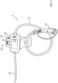
- the figure 1 shows a set 1 consisting of a charging device 2 in the form of a charging cable and a number of different connector adapters 3.
- the charging cable has a control unit 10, e.g. a protection and control box, which is connected to a cable 11, at the end of which is the vehicle connector 12 for connecting to the charging port of the electric vehicle.
- This vehicle connector 12 is set up to be plugged into the charging socket of an electric vehicle in a form-fitting manner.
- the control unit 10 is further connected to a second cable 13 at the end of which another plug in the form of a power source plug connector 14 is located.
- This plug is not compatible with a standard household or industrial plug connection, but can only be connected with plug connection adapters specially made for this set.
- Each connector adapter has on one side a second connector 15, eg a coupling, which is adapted to be connected to the power source connector 14.
- a first plug connector 16 for connection to the charging energy source, for example for the usual plug devices in households and industry.
- each of these plug connection adapters has plug contacts for one to three phases, the neutral conductor and the protective conductor.
- An exception is the connector adapter 3a, which has two control contacts in addition to the three phases, the neutral conductor and the protective conductor.
- This plug-in adapter is designed to be plugged into a public AC charging facility or into a wall box without a charging cable. The two control contacts are used for charging control and signaling of the maximum available charging current that the charging energy source can provide and that can be transmitted via the charging device 2 .
- connector adapters 3a, 3b, 3d, 3e in which the first and second connectors 16, 15 are housed in one housing, and there are connector adapters 3c, 3f, 3g, 3h in which a short cable is between the two connectors 15, 16 is located.
- the charging device 2 with a wall adapter 21 can be seen.
- the wall adapter 21 is firmly integrated into the house installation of the power grid.
- the control unit 10 of the charging device 2 recognizes that it is in a fixed installation after identifying the connector 20.
- the control unit 10 enables all features that are possible at this location.
- Other charging devices 2 can also access the information in the cloud.
- a second charging device 2 which is plugged into a wall adapter whose identifier has already been linked to the location, can access the data in the cloud directly without further input.
- FIG 3 shows a wall adapter 21 with a bracket 30 for receiving and locking the control unit 10 of the charging device 2.
- a lock 32 for example a lock operated with a key or a combination lock, can protect the control unit 10 and thus the entire charging device against theft, which is a great advantage for an installation in a public or semi-public space.
- the bracket 30 has a latch that engages when the control unit 10 is placed in a receiving area of the bracket 30 .
- the lock protects the control unit 10 against falling out or being pulled out. It can be released by a button 31, which retracts the locking projection when it is pressed in and releases the control unit 10 for removal.
- the lock 32 can be used to prevent the button 31 from being pressed in when locked, which protects the system against theft.
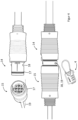
- FIG 4 shows the principle of protecting the adapter plug connection against unauthorized interruption or against theft, for example by a lockable connection of the energy source plug connection 14 and the associated second plug connector 15 of the plug connection adapter.
- Each of the two connector parts has a protective wall 17 in the form of a hollow cylinder around the electrical contacts.
- the diameters of the respective protective walls 17 are matched to one another in such a way that when plugged in, the protective wall of one connector part surrounds the protective wall of the other connector part, so that one connector part forms an outer protective wall and the other has an inner protective wall.
- the inner bulkhead has a tangential bore 18, which bore 18 may or may not be entirely within the bulkhead, for example about 60% to 80%.
- the outer protective wall also has a bore 19 in the tangential direction, resulting in a single bore when the two connector parts are plugged together, ie the bores are aligned with one another.
- a hole 18, 19 Through this hole 18, 19, the straight part of the shackle of a padlock can be inserted and the lock can be locked by snapping.
- figure 4 is not a padlock, but a lock 4 with a wire to see. The wire rope is pulled through the hole formed by the bores 18, 19 of the two adapter parts and the end snapped into the lock. The connector parts are thus mechanically connected to one another and cannot be released without removing the lock 4, ie by pulling out the cable.
Landscapes
- Engineering & Computer Science (AREA)
- Power Engineering (AREA)
- Transportation (AREA)
- Mechanical Engineering (AREA)
- Life Sciences & Earth Sciences (AREA)
- Sustainable Development (AREA)
- Sustainable Energy (AREA)
- Electric Propulsion And Braking For Vehicles (AREA)
- Charge And Discharge Circuits For Batteries Or The Like (AREA)
Applications Claiming Priority (1)
| Application Number | Priority Date | Filing Date | Title |
|---|---|---|---|
| DE102021134295.3A DE102021134295A1 (de) | 2021-12-22 | 2021-12-22 | System zum Aufladen einer Antriebsbatterie |
Publications (1)
| Publication Number | Publication Date |
|---|---|
| EP4201727A1 true EP4201727A1 (fr) | 2023-06-28 |
Family
ID=86498067
Family Applications (1)
| Application Number | Title | Priority Date | Filing Date |
|---|---|---|---|
| EP22215007.0A Pending EP4201727A1 (fr) | 2021-12-22 | 2022-12-20 | Système et chargeur pour charger une batterie d'entraînement |
Country Status (2)
| Country | Link |
|---|---|
| EP (1) | EP4201727A1 (fr) |
| DE (1) | DE102021134295A1 (fr) |
Families Citing this family (2)
| Publication number | Priority date | Publication date | Assignee | Title |
|---|---|---|---|---|
| DE102023111246A1 (de) * | 2023-05-02 | 2024-11-07 | Bayerische Motoren Werke Aktiengesellschaft | Ladekabel mit Diebstahlsicherung für ein elektrisch betriebenes Fahrzeug und Verfahren zu seiner Steuerung |
| DE102024108694B4 (de) | 2024-03-27 | 2025-10-09 | Dr. Ing. H.C. F. Porsche Aktiengesellschaft | Verfahren und Vorrichtung zur Fahrzeugaufladung gemäß einer Adapterspezifikation |
Citations (3)
| Publication number | Priority date | Publication date | Assignee | Title |
|---|---|---|---|---|
| EP2882066B1 (fr) * | 2012-07-30 | 2017-07-26 | Mitsubishi Electric Corporation | Dispositif de charge/décharge |
| EP3453559A1 (fr) * | 2017-09-12 | 2019-03-13 | Dietmar Niederl | Câble de charge et adaptateur permettant le chargement électrique d'un |
| DE102021203363A1 (de) * | 2020-07-27 | 2022-01-27 | Robert Bosch Gesellschaft mit beschränkter Haftung | Ladekabel |
Family Cites Families (3)
| Publication number | Priority date | Publication date | Assignee | Title |
|---|---|---|---|---|
| DE102009025302B4 (de) | 2009-06-15 | 2011-07-28 | Rwe Ag, 45128 | Verbindung zwischen Ladestation und Elektrofahrzeug |
| WO2012099978A2 (fr) | 2011-01-19 | 2012-07-26 | Aerovironment, Inc. | Connecteur pour connexion de véhicule électrique à contrôleur evse incorporé |
| DE102013007330B4 (de) | 2013-04-27 | 2019-11-28 | Volkswagen Aktiengesellschaft | Teilesatz mit Wechselstecker zum länderübergreifenden elektrischen Laden eines Fortbewegungsmittels |
-
2021
- 2021-12-22 DE DE102021134295.3A patent/DE102021134295A1/de active Pending
-
2022
- 2022-12-20 EP EP22215007.0A patent/EP4201727A1/fr active Pending
Patent Citations (3)
| Publication number | Priority date | Publication date | Assignee | Title |
|---|---|---|---|---|
| EP2882066B1 (fr) * | 2012-07-30 | 2017-07-26 | Mitsubishi Electric Corporation | Dispositif de charge/décharge |
| EP3453559A1 (fr) * | 2017-09-12 | 2019-03-13 | Dietmar Niederl | Câble de charge et adaptateur permettant le chargement électrique d'un |
| DE102021203363A1 (de) * | 2020-07-27 | 2022-01-27 | Robert Bosch Gesellschaft mit beschränkter Haftung | Ladekabel |
Also Published As
| Publication number | Publication date |
|---|---|
| DE102021134295A1 (de) | 2023-06-22 |
Similar Documents
| Publication | Publication Date | Title |
|---|---|---|
| EP3453559B1 (fr) | Câble de charge et adaptateur permettant le chargement électrique d'un | |
| DE102021203363B4 (de) | Ladekabel, Anschlussvorrichtung zur Verwendung als erste Anschlussvorrichtung in einem Ladekabel und Anschlussvorrichtung zur Verwendung als zweite Anschlussvorrichtung in einem Ladekabel | |
| DE102019121108B3 (de) | Mobile Ladestation für ein Elektrofahrzeug | |
| WO2019228687A1 (fr) | Unité de chargement pour véhicules électriques | |
| EP2774799B1 (fr) | Procédé de communication entre un véhicule électrique et une borne de charge destinée au chargement électrique d'au moins un dispositif de stockage d'énergie du véhicule électrique | |
| EP3230114B1 (fr) | Dispositif de sécurité et dispositif de fixation permettant de protéger un véhicule | |
| DE102018126949A1 (de) | Ladevorrichtung für elektrofahrzeuge | |
| DE102016214050B4 (de) | Anordnung aus einem Kraftfahrzeug und einem Verbindungsmittel, Kraftfahrzeug und Verbindungsmittel | |
| AT508192B1 (de) | Überwachungsvorrichtung | |
| DE102018126947A1 (de) | Ladestation für elektrofahrzeuge | |
| DE102018126912A1 (de) | Ladevorrichtung für Elektrofahrzeuge | |
| EP3501883B1 (fr) | Adaptateur de charge | |
| DE202021104997U1 (de) | Mobiles Ladekabel und Netzanschlussstation | |
| EP3744561A1 (fr) | Dispositif de charge pour véhicules électriques | |
| DE102017221597B4 (de) | Ladeverbindungsvorrichtung und Ladesystem | |
| DE102021134295A1 (de) | System zum Aufladen einer Antriebsbatterie | |
| DE102011007763A1 (de) | Adapterkabel zur Wandlung eines an einem Fahrzeugladekabel vorgesehenen Anschlusses eines ersten Typs in einen Anschluss zweiten Typs | |
| DE102018112958A1 (de) | Docking Station für Ladestationen | |
| DE102021209521B3 (de) | Versorgungskabel für ein Fahrzeug, Primärverbinder eines Versorgungskabels und Sekundärverbinder eines Versorgungskabels | |
| EP3831643B1 (fr) | Station de recharge de scooter électrique | |
| EP4259476A1 (fr) | Module de commande de charge, station de charge, et système de charge pour commander des processus de charge de moyens de stockage d'énergie de traction pour véhicules électriques | |
| WO2019228679A1 (fr) | Unité de charge pour véhicules électriques | |
| DE19613793A1 (de) | Mehrpolige Steckvorrichtung nach DIN EN 60309/IEC 309 | |
| DE102021119374A1 (de) | Mobiles Ladekabel und Netzanschlussstation | |
| EP3965247B1 (fr) | Système mobile de distribution réseau |
Legal Events
| Date | Code | Title | Description |
|---|---|---|---|
| PUAI | Public reference made under article 153(3) epc to a published international application that has entered the european phase |
Free format text: ORIGINAL CODE: 0009012 |
|
| STAA | Information on the status of an ep patent application or granted ep patent |
Free format text: STATUS: THE APPLICATION HAS BEEN PUBLISHED |
|
| AK | Designated contracting states |
Kind code of ref document: A1 Designated state(s): AL AT BE BG CH CY CZ DE DK EE ES FI FR GB GR HR HU IE IS IT LI LT LU LV MC ME MK MT NL NO PL PT RO RS SE SI SK SM TR |
|
| STAA | Information on the status of an ep patent application or granted ep patent |
Free format text: STATUS: REQUEST FOR EXAMINATION WAS MADE |
|
| 17P | Request for examination filed |
Effective date: 20231221 |
|
| RBV | Designated contracting states (corrected) |
Designated state(s): AL AT BE BG CH CY CZ DE DK EE ES FI FR GB GR HR HU IE IS IT LI LT LU LV MC ME MK MT NL NO PL PT RO RS SE SI SK SM TR |