EP4201758A1 - Batteriefördersystem, batteriewechselstation und batteriewechselverfahren - Google Patents
Batteriefördersystem, batteriewechselstation und batteriewechselverfahren Download PDFInfo
- Publication number
- EP4201758A1 EP4201758A1 EP21859715.1A EP21859715A EP4201758A1 EP 4201758 A1 EP4201758 A1 EP 4201758A1 EP 21859715 A EP21859715 A EP 21859715A EP 4201758 A1 EP4201758 A1 EP 4201758A1
- Authority
- EP
- European Patent Office
- Prior art keywords
- battery
- support structure
- support
- conveying mechanism
- conveying
- Prior art date
- Legal status (The legal status is an assumption and is not a legal conclusion. Google has not performed a legal analysis and makes no representation as to the accuracy of the status listed.)
- Withdrawn
Links
Images



Classifications
-
- B—PERFORMING OPERATIONS; TRANSPORTING
- B60—VEHICLES IN GENERAL
- B60L—PROPULSION OF ELECTRICALLY-PROPELLED VEHICLES; SUPPLYING ELECTRIC POWER FOR AUXILIARY EQUIPMENT OF ELECTRICALLY-PROPELLED VEHICLES; ELECTRODYNAMIC BRAKE SYSTEMS FOR VEHICLES IN GENERAL; MAGNETIC SUSPENSION OR LEVITATION FOR VEHICLES; MONITORING OPERATING VARIABLES OF ELECTRICALLY-PROPELLED VEHICLES; ELECTRIC SAFETY DEVICES FOR ELECTRICALLY-PROPELLED VEHICLES
- B60L53/00—Methods of charging batteries, specially adapted for electric vehicles; Charging stations or on-board charging equipment therefor; Exchange of energy storage elements in electric vehicles
- B60L53/80—Exchanging energy storage elements, e.g. removable batteries
-
- B—PERFORMING OPERATIONS; TRANSPORTING
- B60—VEHICLES IN GENERAL
- B60L—PROPULSION OF ELECTRICALLY-PROPELLED VEHICLES; SUPPLYING ELECTRIC POWER FOR AUXILIARY EQUIPMENT OF ELECTRICALLY-PROPELLED VEHICLES; ELECTRODYNAMIC BRAKE SYSTEMS FOR VEHICLES IN GENERAL; MAGNETIC SUSPENSION OR LEVITATION FOR VEHICLES; MONITORING OPERATING VARIABLES OF ELECTRICALLY-PROPELLED VEHICLES; ELECTRIC SAFETY DEVICES FOR ELECTRICALLY-PROPELLED VEHICLES
- B60L53/00—Methods of charging batteries, specially adapted for electric vehicles; Charging stations or on-board charging equipment therefor; Exchange of energy storage elements in electric vehicles
- B60L53/50—Charging stations characterised by energy-storage or power-generation means
- B60L53/53—Batteries
-
- Y—GENERAL TAGGING OF NEW TECHNOLOGICAL DEVELOPMENTS; GENERAL TAGGING OF CROSS-SECTIONAL TECHNOLOGIES SPANNING OVER SEVERAL SECTIONS OF THE IPC; TECHNICAL SUBJECTS COVERED BY FORMER USPC CROSS-REFERENCE ART COLLECTIONS [XRACs] AND DIGESTS
- Y02—TECHNOLOGIES OR APPLICATIONS FOR MITIGATION OR ADAPTATION AGAINST CLIMATE CHANGE
- Y02T—CLIMATE CHANGE MITIGATION TECHNOLOGIES RELATED TO TRANSPORTATION
- Y02T10/00—Road transport of goods or passengers
- Y02T10/60—Other road transportation technologies with climate change mitigation effect
- Y02T10/70—Energy storage systems for electromobility, e.g. batteries
-
- Y—GENERAL TAGGING OF NEW TECHNOLOGICAL DEVELOPMENTS; GENERAL TAGGING OF CROSS-SECTIONAL TECHNOLOGIES SPANNING OVER SEVERAL SECTIONS OF THE IPC; TECHNICAL SUBJECTS COVERED BY FORMER USPC CROSS-REFERENCE ART COLLECTIONS [XRACs] AND DIGESTS
- Y02—TECHNOLOGIES OR APPLICATIONS FOR MITIGATION OR ADAPTATION AGAINST CLIMATE CHANGE
- Y02T—CLIMATE CHANGE MITIGATION TECHNOLOGIES RELATED TO TRANSPORTATION
- Y02T10/00—Road transport of goods or passengers
- Y02T10/60—Other road transportation technologies with climate change mitigation effect
- Y02T10/7072—Electromobility specific charging systems or methods for batteries, ultracapacitors, supercapacitors or double-layer capacitors
Definitions
- the disclosure relates to a vehicle battery swapping technology, and more particularly to a battery conveying system, a battery swapping station and a battery swapping method.
- a battery swapping station is equipment for swapping a battery for an electric vehicle.
- a conventional battery swapping station 1 is mainly composed of a battery swapping platform 11, a rail guided vehicle (RGV) 12 and a battery storage mechanism 13.
- the battery swapping platform 11 is configured to park and position a vehicle, and the battery storage mechanism 13 is configured to enable storage, transfer and charging operations of batteries.
- the rail guided vehicle 12 is further configured to convey a battery between the battery swapping platform 11 and the battery storage mechanism 13 in addition to enabling operations such as locking and unlocking of the battery.
- the rail guided vehicle 12 needs to exit the battery swapping platform 11 and then be docked with the battery storage mechanism 13 for transporting the battery, so that it is necessary to leave enough space in a conventional battery swapping station 1 to perform a battery transportation operation between the battery swapping platform 11 and the battery storage mechanism 13, resulting in a large overall footprint of the conventional battery swapping station 1, which is not only unfavorable for site selection for equipment in the battery swapping station, but also increases the overall cost of the equipment.
- the disclosure provides a battery conveying system, a battery swapping station and a battery swapping method in order to solve or at least partially solve the above-mentioned problems.
- a first aspect of the disclosure provides a battery conveying system, including a first conveying mechanism and a second conveying mechanism.
- the first conveying mechanism includes a mechanism body; and a first support structure movably arranged on the mechanism body and liftable relative to the mechanism body, the first support structure supporting a battery.
- the second conveying mechanism includes a second support structure configured to support the battery; and a channel structure formed on the second support structure.
- the first support structure is perpendicularly aligned with the channel structure to enable, when the first support structure is being lifted or lowered relative to the mechanism body, the first support structure to run through the channel structure, such that a support surface of the first support structure is higher or lower than a support surface of the second support structure in a horizontal direction, so as to allow the battery to be transported between the first support structure and the second support structure.
- the battery is supported on the support surface of the first support structure or the support surface of the second support structure.
- the battery supported on the support surface of the second support structure is transferable to the support surface of the first support structure when the support surface of the first support structure is being lifted from a position lower than the support surface of the second support structure to a position higher than the support surface of the second support structure; and the battery supported on the support surface of the first support structure is transferable to the support surface of the second support structure when the support surface of the first support structure is being lowered from a position higher than the support surface of the second support structure to a position lower than the support surface of the second support structure.
- the first support structure includes a plurality of first support members arranged in the shape of a comb
- the second support structure includes a plurality of second support members arranged in the shape of a comb
- the channel structure is naturally formed by a gap between every two adjacent second support members
- the first support member and/or the second support member further includes a conveying roller for allowing the first support structure and/or the second support structure to convey the battery in the horizontal direction.
- the second support structure further includes an adjustment member for adjusting the gap between the second support members in the second support structure such that the channel structure is adapted to first support structures of different specifications.
- the second conveying mechanism further includes a carrying device configured to support the second support structure and be movable relative to the first conveying mechanism such that the first conveying mechanism and the second conveying mechanism are located at the docking position.
- the carrying device includes a rail guided vehicle.
- the second conveying mechanism further includes a battery conveying device, and the second support structure is fixedly arranged at the end of the battery conveying device close to the first conveying mechanism.
- the first conveying mechanism further includes a lifting device which is arranged on the mechanism body, connected to the first support structure and configured to drive the first support structure to be lifted or lowered relative to the mechanism body.
- a lifting device which is arranged on the mechanism body, connected to the first support structure and configured to drive the first support structure to be lifted or lowered relative to the mechanism body.
- a second aspect of the disclosure provides a battery swapping station, including: a battery swapping platform for performing a battery dismounting/mounting operation on a vehicle; a battery storage mechanism for storing a battery; and the battery conveying system as described above in the first aspect.
- the first conveying mechanism of the battery conveying system is dockable with the battery storage mechanism for allowing the battery to be conveyed between the battery storage mechanism and the first conveying mechanism
- the second conveying mechanism of the battery conveying system is dockable with the battery swapping platform for allowing the battery to be conveyed between the battery swapping platform and the second conveying mechanism.
- the battery storage mechanism includes a plurality of battery compartments arranged in a stacked manner; and the first support structure of the first conveying mechanism is dockable with one of the battery compartments of the battery storage mechanism when being lifted or lowered relative to the mechanism body in a vertical direction.
- the battery storage mechanism includes two battery storage racks, each of the battery storage racks including a plurality of the battery compartments arranged in a stacked manner, and the first conveying mechanism is provided between the two battery storage racks.
- the battery storage mechanism includes a plurality of battery storage racks arranged side-by-side on one side of the first conveying mechanism, the first conveying mechanism being movable in a horizontal direction of the battery storage racks so as to be docked with one of the plurality of battery storage racks.
- the battery storage rack is arranged on a side portion of the first conveying mechanism in a first axial direction
- the second conveying mechanism is arranged on a side portion of the first conveying mechanism in a second axial direction perpendicular to the first axial direction.
- the battery swapping station further includes charging devices which are respectively arranged in the battery compartments and are configured to be electrically connected to batteries stored in the battery compartments for charging.
- a third aspect of the disclosure provides a battery swapping method applied to the battery swapping station as described above in the second aspect, the method including: conveying a used battery detached from a vehicle from the battery swapping platform to the second conveying mechanism; controlling the second conveying mechanism to be docked with the first conveying mechanism, and causing the support surface of the first support structure of the first conveying mechanism to be lower than the support surface of the second support structure in the horizontal direction; controlling the first support structure to be lifted relative to the mechanism body such that the support surface of the first support structure is lifted from a position lower than the support surface of the second support structure to a position higher than the support surface of the second support structure, so as to transfer the used battery supported on the support surface of the second support structure to the support surface of the first support structure; controlling the first support structure to be lifted or lowered relative to the mechanism body such that the first support structure is docked with an empty battery compartment in the battery storage mechanism, and conveying the used battery from the first support structure to the battery compartment for storage; controlling the first support structure to be lifted or
- the first conveying mechanism having the first support structure and the second conveying mechanism having the second support structure and the channel structure
- the first support structure can run, when being lifted or lowered, through the channel structure of the second conveying mechanism, such that the support surface of the first support structure is higher or lower than the support surface of the second support structure in the horizontal direction, thereby transferring the battery between the first support structure and the second support structure.
- the disclosure can reduce or eliminate a battery transportation area between the first conveying mechanism and the second conveying mechanism, not only shortening a battery transfer path in the battery swapping station, but also effectively reducing the overall footprint of the battery swapping station.
- the first embodiment of the disclosure provides a battery conveying system.
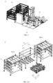
- the battery conveying system 2 of the disclosure mainly includes a first conveying mechanism 21 and a second conveying mechanism 22.
- the first conveying mechanism 21 mainly includes a mechanism body 211 and a first support structure 212.
- the first support structure 212 is movably arranged on the mechanism body 211 and can be lifted or lowered relative to the mechanism body 211, and the first support structure 212 is configured to support a battery.
- the first conveying mechanism 21 further includes a lifting device 213 which is arranged on the mechanism body 211, connected to the first support structure 212 and configured to drive the first support structure 212 to be lifted or lowered relative to the mechanism body 211.
- the mechanism body 211 is a frame structure.
- the first support structure 212 includes a plurality of first support members 2121 arranged in the shape of a comb.
- the lifting device 213 may include a lifting chain and a driving motor.
- the lifting chain is connected to the first support structure 212 and drives the first support structure 212 to be lifted or lowered relative to the mechanism body 211 by means of a driving force provided by the driving motor.
- the structural arrangement of the lifting device 213 is not limited to the above embodiment, and may also be adjusted according to actual requirements, which is not limited in the disclosure.
- the second conveying mechanism 22 includes a second support structure 221 and a channel structure 2210.
- the second support structure 221 is configured to support the battery.
- the second support structure 221 includes a plurality of second support members 2211 arranged in the shape of a comb.
- the channel structure 2210 is formed in the second support structure 221.
- the channel structure 2210 is naturally formed by a gap between every two adjacent second support members 2211.
- the second conveying mechanism 22 and the first conveying mechanism 21 may be located at a docking position for allowing the battery to be transported between the first conveying mechanism 21 and the second conveying mechanism 22.
- the second conveying mechanism 22 may include a carrying device 222 (as shown in Figs. 5A and 5B ) that is configured to support the second support structure 221 and can move relative to the first conveying mechanism 21 such that the first conveying mechanism 21 and the second conveying mechanism 22 are located at the docking position.
- a carrying device 222 as shown in Figs. 5A and 5B ) that is configured to support the second support structure 221 and can move relative to the first conveying mechanism 21 such that the first conveying mechanism 21 and the second conveying mechanism 22 are located at the docking position.
- the carrying device 222 is, for example, a rail guided vehicle (RGV), but is not limited thereto.
- the carrying device 222 may also be implemented using other apparatuses having a moving function, which is not limited in the disclosure.
- the second conveying mechanism 22 may further include a battery conveying device 223 (as shown in Figs. 6A and 6B ).
- the second support structure 221 is fixedly arranged at the end of the battery conveying device 223 close to the first conveying mechanism 21 and is kept in a docking position relationship with the first support structure 212.
- the second support structure 221 and the battery conveying device 223 may be implemented using an integrally formed structural design or may be implemented in a fixed connection manner.
- the first support structure 212 is perpendicularly aligned with the channel structure 2210 to enable, when the first support structure 212 is being lifted or lowered relative to the mechanism body 211, the first support structure 212 to run through the channel structure 2210, such that a support surface of the first support structure 212 is higher or lower than a support surface of the second support structure 221 in a horizontal direction, so as to allow the battery to be transported between the first support structure 212 and the second support structure 221.
- the battery 6 may be supported on the support surface 212a of the first support structure 212 or the support surface 221a of the second support structure 221.
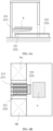
- the support surface 212a of the first support structure 212 is being lifted from a position lower than the support surface 221a of the second support structure 221 to a position higher than the support surface 221a of the second support structure 221 (i.e., when it is switched from the state shown in Fig. 5A into the state shown in Fig. 5B )
- the battery 6 supported on the support surface 221a of the second support structure 221 can be transferred to the support surface 212a of the first support structure 212.
- the battery supported on the support surface 212a of the first support structure 212 can be transferred to the support surface 221a of the second support structure 221. Therefore, the battery 6 is transported between the first support structure 212 and the second support structure 221.
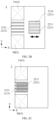
- the first support structure 212 and the second support structure 221 are respectively composed of a plurality of first support members 2121 and a plurality of second support members 2211 arranged in the shape of a comb. Therefore, it can be clearly seen from Figs. 2B and 2C that when the first conveying mechanism 21 and the second conveying mechanism 22 are located at the docking position, as viewed from the top, the first support members 2121 and the second support members 2211 are arranged in a staggered manner (i.e., in the state shown in Fig. 2C ). That is to say, with the structural design of the disclosure, an operating space required for transporting the battery between the first conveying mechanism 21 and the second conveying mechanism 22 is reduced, and the overall footprint of the battery conveying system 2 is reduced.
- the second support structure 221 may further include an adjustment member (not shown) that may be configured to adjust a gap between the second support members 2211 in the second support structure 221, such that the channel structure 2210 formed by the gap between every two adjacent second support members 2211 is adapted to the first support structure 212. That is to say, the first support members 2121 in the first support structure 212 are respectively aligned with the gap in the channel structure 2212 in terms of position when the first conveying mechanism 21 and the second conveying mechanism 22 are located at the docking position.
- an adjustment member (not shown) that may be configured to adjust a gap between the second support members 2211 in the second support structure 221, such that the channel structure 2210 formed by the gap between every two adjacent second support members 2211 is adapted to the first support structure 212. That is to say, the first support members 2121 in the first support structure 212 are respectively aligned with the gap in the channel structure 2212 in terms of position when the first conveying mechanism 21 and the second conveying mechanism 22 are located at the docking position.
- the channel structure 2210 of the second conveying mechanism 22 adapted to first support structures 212 of different specifications, so that the range of application of the second conveying mechanism 22 can be expanded.
- first support member 2121 of the first support structure 212 and/or the second support member 2211 of the second support structure 221 further includes a conveying roller for enabling the first support structure 212 and/or the second support structure 221 to convey the battery in the horizontal direction, for example, to enable the conveying of the battery between the first conveying mechanism 21 and the second conveying mechanism 22 and other apparatuses or mechanisms.
- the second embodiment of the disclosure provides a battery swapping station.
- the battery swapping station of the disclosure mainly includes a battery swapping platform, battery storage mechanisms and a battery conveying system according to the first embodiment described above.
- the battery swapping platform (not shown) is configured to perform a battery dismounting/mounting operation on the vehicle, i.e., to dismount a used battery from the vehicle or mount a fully-charged battery to the vehicle.
- the battery storage mechanisms 5A and 5B are configured to store batteries.
- the battery conveying system includes a first conveying mechanism 21 and a second conveying mechanism 22 that are configured to convey batteries between the battery swapping platform and the battery storage mechanisms 5A, 5B.
- the first conveying mechanism 21 of the battery conveying system 2 may be docked with the battery storage mechanisms 5A, 5B for allowing batteries to be transported and conveyed between the battery storage mechanisms 5A, 5B and the first conveying mechanism 21, and the second conveying mechanism 22 of the battery conveying system 2 may be docked with the battery swapping platform for allowing a battery to be transported and conveyed between the battery swapping platform and the second conveying mechanism 22.
- the first support structure 212 in the first conveying mechanism 21 may include a plurality of first support members 2121 arranged in the shape of a comb.
- Each first support member 2121 is composed, for example, of a conveying roller, for allowing a battery to be conveyed in the horizontal direction between the first support structure 212 and the battery storage mechanism 5 after the first support structure 212 is docked with the battery storage mechanism 5.
- the battery storage mechanisms 5A, 5B each include a plurality of battery compartments 51 arranged in a stacked manner.
- the first support structure 212 of the first conveying mechanism 21 may be docked, when being lifted or lowered relative to the mechanism body 211 under the drive of the lifting device 213, with a designated battery compartment 51 in the battery storage mechanisms 5A, 5B for allowing a battery to be conveyed between the first support structure 212 and the designated battery compartment 51.
- the second support structure 221 of the second conveying mechanism 22 may further include a plurality of second support members 2211 arranged in the shape of a comb, each second support member 2211 being composed, for example, of a conveying roller, for allowing a battery to be conveyed in the horizontal direction between the second support structure 221 and the battery swapping platform after the second support structure 221 is docked with the battery swapping platform.
- the second conveying mechanism 22 may include a carrying device 222.
- the carrying device 222 may move along a preset traveling track between the first conveying mechanism 21 and the battery swapping platform to allow for the mutual docking of the second conveying mechanism 22 and the first conveying mechanism 21, thereby transporting and transferring a battery between the first support structure 212 and the second support structure 221, or to allow for the mutual docking of the second conveying mechanism 22 and a battery dismounting/mounting structure (not shown) of the battery swapping platform, thereby transporting and conveying a battery between the second support structure 221 and the battery dismounting/mounting structure.
- the second conveying mechanism 22 is, for example, a rail guided vehicle including the second support structure 221.
- the second conveying mechanism 22 may further include a battery conveying device 223, the second support structure 221 may be fixedly arranged at the end of the battery conveying device 223 close to the first conveying mechanism 21, and the end of the battery conveying device 223 away from the first conveying mechanism 21 may be mutually docked with the battery dismounting/mounting mechanism (not shown) of the battery swapping platform 4, thereby allowing the battery to be conveyed between the second support structure 221 and the battery dismounting/mounting mechanism of the battery swapping platform 4 by means of the battery conveying device 223.
- the battery conveying device 223 is, for example, a conveying mechanism such as a roller conveying line, a chain conveying line, a belt conveying line, etc., which is not limited in the disclosure.
- no battery conveying device 223 is provided, and only the second support structure 221 is configured to dock with the first conveying mechanism 21 and the battery dismounting/mounting mechanism of the battery swapping platform 4 respectively.
- the battery storage mechanism 5 may include two battery storage racks 5A, 5B.
- the battery storage racks 5A, 5B each includes a plurality of battery compartments 51 arranged in a stacked manner.
- the first conveying mechanism 21 may be arranged between the two battery storage racks 5A, 5B to enable the first support structure 212 of the first conveying mechanism 21, when being lifted or lowered relative to the mechanism body 211 in a vertical direction under the drive of the lifting device 213, to be mutually docked with a designated battery compartment 51 in the battery storage rack 5A or 5B, thereby performing a battery conveying operation between the battery compartment 51 and the first support structure 212.
- the battery storage mechanism 5 may further include a plurality of battery storage racks 5A, 5B arranged side-by-side on one side of the first conveying mechanism 21.
- the first conveying mechanism 21 can move in a horizontal direction of the battery storage racks 5A, 5B so as to be docked with one of the plurality of battery storage racks 5A, 5B.
- a guide rail may be added below the first conveying mechanism 21 so that the first conveying mechanism 21 can move along the guide rail between the plurality of battery storage racks 5A, 5B arranged side-by-side, and the capacity of the battery compartment 51 is thus increased.
- the battery storage racks 5A, 5B are arranged on one side or two opposite sides of the first conveying mechanism 21 in a first axial direction (i.e., the Y-axis direction shown in Fig. 2B ), and the second conveying mechanism 22 is arranged on one side of the first conveying mechanism 21 in a second axial direction perpendicular to the first axial direction (i.e., the X-axis direction shown in Fig. 2B ).
- the overall layout of the battery swapping station can be more compact, and the overall footprint of the battery swapping station is accordingly decreased.
- the battery swapping station may further include charging devices (not shown) which are respectively arranged in the battery compartments 51 and are configured to be electrically connected to batteries stored in the battery compartments 51 for charging.
- the battery swapping station may further include a rest room 7 and a control room 8.
- the control room 8 is responsible for respective operations of the battery conveying system, the battery swapping platform and the battery storage mechanisms 5A, 5B, and is further responsible for cooperative operations between the battery conveying system and the battery swapping platform and the battery storage mechanisms 5A, 5B.
- the control room 8 may be configured to provide an equipment room, an electrical cabinet, a cooling device, a power distribution cabinet, etc. and be responsible for the logical control of movements of constituent components in the entire battery swapping station, such as dismounting/mounting, transfer and conveying, and charging and cooling operations of batteries, etc.
- the rest room 8 is configured to provide a rest area for an operator of the battery swapping station and/or a vehicle owner (user).
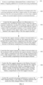
- the third embodiment of the disclosure provides a battery swapping method applied to the battery swapping station as described above in the second aspect, the method including the following steps.
- step S81 a used battery detached from a vehicle is conveyed from the battery swapping platform to the second conveying mechanism.
- the vehicle may be driven into and positioned on the battery swapping platform, such that the used battery is dismounted from the vehicle by means of the battery dismounting/mounting mechanism of the battery swapping platform, and the used battery dismounted is conveyed from the battery swapping platform to the second support structure of the second conveying mechanism.
- step S82 the second conveying mechanism is controlled to be docked with the first conveying mechanism, and the support surface of the first support structure of the first conveying mechanism is caused to be lower than the support surface of the second support structure in the horizontal direction.
- the carrying device may support the used battery and move same from the battery swapping platform toward the first conveying mechanism when it is determined that the support surface of the first support structure of the first conveying mechanism is lower than the support surface of the second support structure in the horizontal direction, such that the second conveying mechanism and the first conveying mechanism are located at a docking position.
- the battery conveying device can directly convey the used battery from the battery swapping platform to the second support structure when it is determined that the support surface of the first support structure of the first conveying mechanism is lower than the support surface of the second support structure in the horizontal direction.
- step S83 the first support structure is controlled to be lifted relative to the mechanism body such that the support surface of the first support structure is lifted from a position lower than the support surface of the second support structure to a position higher than the support surface of the second support structure, so as to transfer the used battery supported on the support surface of the second support structure to the support surface of the first support structure (i.e., it is switched from the state shown in Fig. 5A to the state shown in Fig. 5B ).
- step S84 the first conveying mechanism is controlled to lifted or lower relative to the mechanism body such that the first support structure is docked with an empty battery compartment in the battery storage mechanism, and the used battery is conveyed from the first support structure to the battery compartment for storage and charging.
- step S85 the first support structure is controlled to be lifted or lowered relative to the mechanism body such that the first support structure is docked with a battery compartment in the battery storage mechanism that stores a fully-charged battery, and the fully-charged battery is conveyed from the battery compartment to the first support structure.
- step S86 the first support structure is controlled to be lowered relative to the mechanism body such that the support surface of the first support structure is lowered from a position higher than the support surface of the second support structure to a position lower than the support surface of the second support structure, so as to transfer the fully-charged battery supported on the support surface of the first support structure to the support surface of the second support structure (i.e., it is switched from the state shown in Fig. 5B to the state shown in Fig. 5A ).
- step S87 the second conveying mechanism is controlled to convey the fully-charged battery to the battery swapping platform, and the fully-charged battery is mounted to the vehicle.
- the first support structure of the first conveying mechanism can run through the channel structure of the second conveying mechanism during lifting or lowering, such that the support surface of the first support structure is higher or lower than the support surface of the second support structure in the horizontal direction, thereby allowing battery to be transferred between the first support structure and the second support structure.
- the first conveying mechanism and the second conveying mechanism are located at the docking position, as viewed from the top, the first support structure of the first conveying mechanism and the second support structure of the second conveying mechanism are arranged in a staggered manner.
- the disclosure can greatly reduce or eliminate the transportation area between the first conveying mechanism and the second conveying mechanism and accordingly decreases the overall footprint of the battery swapping station, which not only facilitates site selection for equipment in the battery swapping station, but also reduces the overall cost of the equipment.
- the disclosure greatly reduces or eliminates the transportation position between the first conveying mechanism and the second conveying mechanism, the distance between the battery swapping platform and the battery storage mechanism in the battery swapping station can be relatively shortened, the transfer path of the battery therebetween is shortened, and the efficiency of battery transportation and transfer is improved.
Landscapes
- Engineering & Computer Science (AREA)
- Power Engineering (AREA)
- Transportation (AREA)
- Mechanical Engineering (AREA)
- Arrangement Or Mounting Of Propulsion Units For Vehicles (AREA)
- Charge And Discharge Circuits For Batteries Or The Like (AREA)
- Electric Propulsion And Braking For Vehicles (AREA)
Applications Claiming Priority (2)
| Application Number | Priority Date | Filing Date | Title |
|---|---|---|---|
| CN202010868352.4A CN111959341A (zh) | 2020-08-24 | 2020-08-24 | 电池传输系统、换电站及换电方法 |
| PCT/CN2021/095152 WO2022041870A1 (zh) | 2020-08-24 | 2021-05-21 | 电池传输系统、换电站及换电方法 |
Publications (2)
| Publication Number | Publication Date |
|---|---|
| EP4201758A1 true EP4201758A1 (de) | 2023-06-28 |
| EP4201758A4 EP4201758A4 (de) | 2024-02-28 |
Family
ID=73390945
Family Applications (1)
| Application Number | Title | Priority Date | Filing Date |
|---|---|---|---|
| EP21859715.1A Withdrawn EP4201758A4 (de) | 2020-08-24 | 2021-05-21 | Batteriefördersystem, batteriewechselstation und batteriewechselverfahren |
Country Status (5)
| Country | Link |
|---|---|
| US (1) | US20240025290A1 (de) |
| EP (1) | EP4201758A4 (de) |
| CN (1) | CN111959341A (de) |
| TW (1) | TWI759070B (de) |
| WO (1) | WO2022041870A1 (de) |
Cited By (1)
| Publication number | Priority date | Publication date | Assignee | Title |
|---|---|---|---|---|
| CN117465283A (zh) * | 2023-12-27 | 2024-01-30 | 宁波格劳博智能工业有限公司 | 一种电池包快换支架、电池包换电站以及换电方法 |
Families Citing this family (5)
| Publication number | Priority date | Publication date | Assignee | Title |
|---|---|---|---|---|
| CN111959341A (zh) * | 2020-08-24 | 2020-11-20 | 武汉蔚来能源有限公司 | 电池传输系统、换电站及换电方法 |
| CN114683921A (zh) * | 2020-12-31 | 2022-07-01 | 奥动新能源汽车科技有限公司 | 换电站 |
| CN115723617A (zh) * | 2021-08-31 | 2023-03-03 | 比亚迪股份有限公司 | 轨道车辆自动换电控制方法、系统、电子设备及存储介质 |
| CN114435179B (zh) * | 2022-04-07 | 2022-06-17 | 深圳万甲荣实业有限公司 | 一种新能源汽车流动换电车及换电池方法 |
| CN116748192B (zh) * | 2023-06-29 | 2026-02-24 | 蔚来电池科技(安徽)有限公司 | 载托治具、输送线及电池清洗装置 |
Family Cites Families (22)
| Publication number | Priority date | Publication date | Assignee | Title |
|---|---|---|---|---|
| IL218924A (en) * | 2012-03-29 | 2016-03-31 | Better Place GmbH | Battery replacement system and method for electric vehicles |
| CN202609431U (zh) * | 2012-05-08 | 2012-12-19 | 许继集团有限公司 | 一种电池仓交换平台 |
| DE102014226372A1 (de) * | 2014-12-18 | 2016-06-23 | Kuka Systems Gmbh | Verfahren zum Wechseln von Fahrzeugenergiespeichern und Energiespeicherwechseleinrichtung |
| JP6853505B2 (ja) * | 2017-03-16 | 2021-03-31 | 三菱自動車工業株式会社 | バッテリパック交換装置 |
| CN207860149U (zh) * | 2017-11-22 | 2018-09-14 | 蔚来汽车有限公司 | 电动汽车的自动换电平台和换电站 |
| CN108216151A (zh) * | 2018-02-28 | 2018-06-29 | 蔚来汽车有限公司 | 电池仓、新能源汽车换电站及电池存储转运方法 |
| CN208217606U (zh) * | 2018-04-09 | 2018-12-11 | 博众精工科技股份有限公司 | 充电仓电池交换机构 |
| CN109278719A (zh) * | 2018-10-18 | 2019-01-29 | 博众精工科技股份有限公司 | 一种汽车换电站的扩容式充电仓 |
| CN110027518A (zh) * | 2018-10-19 | 2019-07-19 | 上海蔚来汽车有限公司 | 运输装置、交接机构和换电系统 |
| EP3663126A1 (de) * | 2018-12-06 | 2020-06-10 | Battswap, Inc. | Batteriespeicher- und ladesystem |
| CN209479636U (zh) * | 2018-12-20 | 2019-10-11 | 蔚来汽车有限公司 | 电池包交换装置、电池包存储系统和换电站 |
| CN210116392U (zh) * | 2019-03-20 | 2020-02-28 | 上海蔚来汽车有限公司 | 接驳站及具有该接驳站的充换电站 |
| CN110789394B (zh) * | 2019-09-27 | 2020-12-15 | 王丹 | 一种动力电池自动换电方法 |
| CN111267789B (zh) * | 2020-01-31 | 2022-08-05 | 山东蓝擎重工科技有限公司 | 一种新能源车换电系统 |
| CN111301360A (zh) * | 2020-03-04 | 2020-06-19 | 博众精工科技股份有限公司 | 简易换电系统、换电方法和换电站 |
| CN111301358A (zh) * | 2020-03-04 | 2020-06-19 | 博众精工科技股份有限公司 | 单缓存换电系统、换电方法和换电站 |
| CN111469706B (zh) * | 2020-04-30 | 2021-09-14 | 博众精工科技股份有限公司 | 一种电池缓存装置 |
| CN111959341A (zh) * | 2020-08-24 | 2020-11-20 | 武汉蔚来能源有限公司 | 电池传输系统、换电站及换电方法 |
| CN213056772U (zh) * | 2020-08-24 | 2021-04-27 | 武汉蔚来能源有限公司 | 电池传输系统及换电站 |
| EP4212382B1 (de) * | 2021-08-27 | 2025-08-06 | Contemporary Amperex Technology (Hong Kong) Limited | Batteriewechselplattform und batteriewechselstation |
| IT202200027342A1 (it) * | 2022-12-30 | 2024-06-30 | Tecnobus Ind S R L | Apparecchiatura automatica per la sostituzione di batterie di veicoli a propulsione elettrica |
| US12017622B1 (en) * | 2023-03-24 | 2024-06-25 | Ford Global Technologies, Llc | Systems and methods for a battery exchange system |
-
2020
- 2020-08-24 CN CN202010868352.4A patent/CN111959341A/zh active Pending
-
2021
- 2021-01-13 TW TW110101232A patent/TWI759070B/zh not_active IP Right Cessation
- 2021-05-21 US US18/042,742 patent/US20240025290A1/en active Pending
- 2021-05-21 EP EP21859715.1A patent/EP4201758A4/de not_active Withdrawn
- 2021-05-21 WO PCT/CN2021/095152 patent/WO2022041870A1/zh not_active Ceased
Cited By (1)
| Publication number | Priority date | Publication date | Assignee | Title |
|---|---|---|---|---|
| CN117465283A (zh) * | 2023-12-27 | 2024-01-30 | 宁波格劳博智能工业有限公司 | 一种电池包快换支架、电池包换电站以及换电方法 |
Also Published As
| Publication number | Publication date |
|---|---|
| US20240025290A1 (en) | 2024-01-25 |
| EP4201758A4 (de) | 2024-02-28 |
| TW202208202A (zh) | 2022-03-01 |
| WO2022041870A1 (zh) | 2022-03-03 |
| TWI759070B (zh) | 2022-03-21 |
| CN111959341A (zh) | 2020-11-20 |
Similar Documents
| Publication | Publication Date | Title |
|---|---|---|
| EP4201758A1 (de) | Batteriefördersystem, batteriewechselstation und batteriewechselverfahren | |
| EP4173884B1 (de) | Batteriewechselplattform, batteriewechselstation und batteriewechselverfahren | |
| CN107399302B (zh) | 充换电站及换电方法 | |
| EP3725606A1 (de) | Batterielade- und wechselstation | |
| WO2019100658A1 (zh) | 电动汽车的自动换电平台和换电站 | |
| EP3760500A1 (de) | Batteriefach, station zum austauschen einer fahrzeugbatterie mit neuer energie und batteriespeicher und transferverfahren | |
| CN210422015U (zh) | 换电系统 | |
| WO2019114546A1 (zh) | 充换电站 | |
| CN207790356U (zh) | 电动汽车的自动换电平台和换电站 | |
| CN112319302B (zh) | 一种电动商用车换电系统 | |
| WO2019100659A1 (zh) | 电动汽车的自动换电平台和换电站 | |
| CN207029135U (zh) | 充换电站 | |
| CN207535878U (zh) | 电动汽车的自动换电平台和换电站 | |
| CN212667169U (zh) | 换电系统 | |
| CN212667171U (zh) | 电池传输系统及其换电站 | |
| WO2024139980A1 (zh) | 一种电池包存放装置、电连接装置及电池仓位内电池包转运方法 | |
| WO2009150303A1 (en) | Electrically driven straddle carrier, terminal tractor or corresponding | |
| CN115303121A (zh) | 电池包换电移动组件、换电穿梭车 | |
| CN213056772U (zh) | 电池传输系统及换电站 | |
| CN216374253U (zh) | 优化换电通道布局的换电站 | |
| CN216377370U (zh) | 具有随动式驱动机构的电池转运设备及电池转运系统 | |
| CN217730259U (zh) | 一种可拓展的集成换电站 | |
| KR20180111160A (ko) | 적재물 인입출 대차 | |
| CN216300840U (zh) | 优化仓位布设的换电站 | |
| CN218750265U (zh) | 电动车辆 |
Legal Events
| Date | Code | Title | Description |
|---|---|---|---|
| STAA | Information on the status of an ep patent application or granted ep patent |
Free format text: STATUS: THE INTERNATIONAL PUBLICATION HAS BEEN MADE |
|
| PUAI | Public reference made under article 153(3) epc to a published international application that has entered the european phase |
Free format text: ORIGINAL CODE: 0009012 |
|
| STAA | Information on the status of an ep patent application or granted ep patent |
Free format text: STATUS: REQUEST FOR EXAMINATION WAS MADE |
|
| 17P | Request for examination filed |
Effective date: 20230321 |
|
| AK | Designated contracting states |
Kind code of ref document: A1 Designated state(s): AL AT BE BG CH CY CZ DE DK EE ES FI FR GB GR HR HU IE IS IT LI LT LU LV MC MK MT NL NO PL PT RO RS SE SI SK SM TR |
|
| DAV | Request for validation of the european patent (deleted) | ||
| DAX | Request for extension of the european patent (deleted) | ||
| A4 | Supplementary search report drawn up and despatched |
Effective date: 20240129 |
|
| RIC1 | Information provided on ipc code assigned before grant |
Ipc: B60S 5/06 20190101AFI20240123BHEP |
|
| STAA | Information on the status of an ep patent application or granted ep patent |
Free format text: STATUS: EXAMINATION IS IN PROGRESS |
|
| 17Q | First examination report despatched |
Effective date: 20250205 |
|
| STAA | Information on the status of an ep patent application or granted ep patent |
Free format text: STATUS: THE APPLICATION HAS BEEN WITHDRAWN |
|
| 18W | Application withdrawn |
Effective date: 20250804 |