EP4201775B1 - Appareil de traitement d'informations, système de véhicule et procédé de traitement d'informations - Google Patents
Appareil de traitement d'informations, système de véhicule et procédé de traitement d'informations Download PDFInfo
- Publication number
- EP4201775B1 EP4201775B1 EP22216177.0A EP22216177A EP4201775B1 EP 4201775 B1 EP4201775 B1 EP 4201775B1 EP 22216177 A EP22216177 A EP 22216177A EP 4201775 B1 EP4201775 B1 EP 4201775B1
- Authority
- EP
- European Patent Office
- Prior art keywords
- vehicle
- driving support
- point
- support function
- points
- Prior art date
- Legal status (The legal status is an assumption and is not a legal conclusion. Google has not performed a legal analysis and makes no representation as to the accuracy of the status listed.)
- Active
Links
Images








Classifications
-
- B—PERFORMING OPERATIONS; TRANSPORTING
- B60—VEHICLES IN GENERAL
- B60W—CONJOINT CONTROL OF VEHICLE SUB-UNITS OF DIFFERENT TYPE OR DIFFERENT FUNCTION; CONTROL SYSTEMS SPECIALLY ADAPTED FOR HYBRID VEHICLES; ROAD VEHICLE DRIVE CONTROL SYSTEMS FOR PURPOSES NOT RELATED TO THE CONTROL OF A PARTICULAR SUB-UNIT
- B60W50/00—Details of control systems for road vehicle drive control not related to the control of a particular sub-unit, e.g. process diagnostic or vehicle driver interfaces
- B60W50/06—Improving the dynamic response of the control system, e.g. improving the speed of regulation or avoiding hunting or overshoot
-
- B—PERFORMING OPERATIONS; TRANSPORTING
- B60—VEHICLES IN GENERAL
- B60R—VEHICLES, VEHICLE FITTINGS, OR VEHICLE PARTS, NOT OTHERWISE PROVIDED FOR
- B60R16/00—Electric or fluid circuits specially adapted for vehicles and not otherwise provided for; Arrangement of elements of electric or fluid circuits specially adapted for vehicles and not otherwise provided for
- B60R16/02—Electric or fluid circuits specially adapted for vehicles and not otherwise provided for; Arrangement of elements of electric or fluid circuits specially adapted for vehicles and not otherwise provided for electric constitutive elements
- B60R16/023—Electric or fluid circuits specially adapted for vehicles and not otherwise provided for; Arrangement of elements of electric or fluid circuits specially adapted for vehicles and not otherwise provided for electric constitutive elements for transmission of signals between vehicle parts or subsystems
-
- B—PERFORMING OPERATIONS; TRANSPORTING
- B60—VEHICLES IN GENERAL
- B60W—CONJOINT CONTROL OF VEHICLE SUB-UNITS OF DIFFERENT TYPE OR DIFFERENT FUNCTION; CONTROL SYSTEMS SPECIALLY ADAPTED FOR HYBRID VEHICLES; ROAD VEHICLE DRIVE CONTROL SYSTEMS FOR PURPOSES NOT RELATED TO THE CONTROL OF A PARTICULAR SUB-UNIT
- B60W30/00—Purposes of road vehicle drive control systems not related to the control of a particular sub-unit, e.g. of systems using conjoint control of vehicle sub-units
- B60W30/18—Propelling the vehicle
- B60W30/182—Selecting between different operative modes, e.g. comfort and performance modes
-
- B—PERFORMING OPERATIONS; TRANSPORTING
- B60—VEHICLES IN GENERAL
- B60W—CONJOINT CONTROL OF VEHICLE SUB-UNITS OF DIFFERENT TYPE OR DIFFERENT FUNCTION; CONTROL SYSTEMS SPECIALLY ADAPTED FOR HYBRID VEHICLES; ROAD VEHICLE DRIVE CONTROL SYSTEMS FOR PURPOSES NOT RELATED TO THE CONTROL OF A PARTICULAR SUB-UNIT
- B60W50/00—Details of control systems for road vehicle drive control not related to the control of a particular sub-unit, e.g. process diagnostic or vehicle driver interfaces
- B60W50/08—Interaction between the driver and the control system
- B60W50/14—Means for informing the driver, warning the driver or prompting a driver intervention
-
- B—PERFORMING OPERATIONS; TRANSPORTING
- B60—VEHICLES IN GENERAL
- B60W—CONJOINT CONTROL OF VEHICLE SUB-UNITS OF DIFFERENT TYPE OR DIFFERENT FUNCTION; CONTROL SYSTEMS SPECIALLY ADAPTED FOR HYBRID VEHICLES; ROAD VEHICLE DRIVE CONTROL SYSTEMS FOR PURPOSES NOT RELATED TO THE CONTROL OF A PARTICULAR SUB-UNIT
- B60W60/00—Drive control systems specially adapted for autonomous road vehicles
- B60W60/001—Planning or execution of driving tasks
-
- G—PHYSICS
- G01—MEASURING; TESTING
- G01C—MEASURING DISTANCES, LEVELS OR BEARINGS; SURVEYING; NAVIGATION; GYROSCOPIC INSTRUMENTS; PHOTOGRAMMETRY OR VIDEOGRAMMETRY
- G01C21/00—Navigation; Navigational instruments not provided for in groups G01C1/00 - G01C19/00
- G01C21/38—Electronic maps specially adapted for navigation; Updating thereof
- G01C21/3804—Creation or updating of map data
- G01C21/3807—Creation or updating of map data characterised by the type of data
-
- H—ELECTRICITY
- H04—ELECTRIC COMMUNICATION TECHNIQUE
- H04L—TRANSMISSION OF DIGITAL INFORMATION, e.g. TELEGRAPHIC COMMUNICATION
- H04L67/00—Network arrangements or protocols for supporting network services or applications
- H04L67/01—Protocols
- H04L67/12—Protocols specially adapted for proprietary or special-purpose networking environments, e.g. medical networks, sensor networks, networks in vehicles or remote metering networks
-
- B—PERFORMING OPERATIONS; TRANSPORTING
- B60—VEHICLES IN GENERAL
- B60W—CONJOINT CONTROL OF VEHICLE SUB-UNITS OF DIFFERENT TYPE OR DIFFERENT FUNCTION; CONTROL SYSTEMS SPECIALLY ADAPTED FOR HYBRID VEHICLES; ROAD VEHICLE DRIVE CONTROL SYSTEMS FOR PURPOSES NOT RELATED TO THE CONTROL OF A PARTICULAR SUB-UNIT
- B60W50/00—Details of control systems for road vehicle drive control not related to the control of a particular sub-unit, e.g. process diagnostic or vehicle driver interfaces
- B60W50/08—Interaction between the driver and the control system
- B60W50/14—Means for informing the driver, warning the driver or prompting a driver intervention
- B60W2050/146—Display means
-
- B—PERFORMING OPERATIONS; TRANSPORTING
- B60—VEHICLES IN GENERAL
- B60W—CONJOINT CONTROL OF VEHICLE SUB-UNITS OF DIFFERENT TYPE OR DIFFERENT FUNCTION; CONTROL SYSTEMS SPECIALLY ADAPTED FOR HYBRID VEHICLES; ROAD VEHICLE DRIVE CONTROL SYSTEMS FOR PURPOSES NOT RELATED TO THE CONTROL OF A PARTICULAR SUB-UNIT
- B60W2552/00—Input parameters relating to infrastructure
- B60W2552/30—Road curve radius
-
- B—PERFORMING OPERATIONS; TRANSPORTING
- B60—VEHICLES IN GENERAL
- B60W—CONJOINT CONTROL OF VEHICLE SUB-UNITS OF DIFFERENT TYPE OR DIFFERENT FUNCTION; CONTROL SYSTEMS SPECIALLY ADAPTED FOR HYBRID VEHICLES; ROAD VEHICLE DRIVE CONTROL SYSTEMS FOR PURPOSES NOT RELATED TO THE CONTROL OF A PARTICULAR SUB-UNIT
- B60W2555/00—Input parameters relating to exterior conditions, not covered by groups B60W2552/00, B60W2554/00
- B60W2555/20—Ambient conditions, e.g. wind or rain
-
- B—PERFORMING OPERATIONS; TRANSPORTING
- B60—VEHICLES IN GENERAL
- B60W—CONJOINT CONTROL OF VEHICLE SUB-UNITS OF DIFFERENT TYPE OR DIFFERENT FUNCTION; CONTROL SYSTEMS SPECIALLY ADAPTED FOR HYBRID VEHICLES; ROAD VEHICLE DRIVE CONTROL SYSTEMS FOR PURPOSES NOT RELATED TO THE CONTROL OF A PARTICULAR SUB-UNIT
- B60W2556/00—Input parameters relating to data
- B60W2556/10—Historical data
-
- B—PERFORMING OPERATIONS; TRANSPORTING
- B60—VEHICLES IN GENERAL
- B60W—CONJOINT CONTROL OF VEHICLE SUB-UNITS OF DIFFERENT TYPE OR DIFFERENT FUNCTION; CONTROL SYSTEMS SPECIALLY ADAPTED FOR HYBRID VEHICLES; ROAD VEHICLE DRIVE CONTROL SYSTEMS FOR PURPOSES NOT RELATED TO THE CONTROL OF A PARTICULAR SUB-UNIT
- B60W2556/00—Input parameters relating to data
- B60W2556/45—External transmission of data to or from the vehicle
-
- B—PERFORMING OPERATIONS; TRANSPORTING
- B60—VEHICLES IN GENERAL
- B60W—CONJOINT CONTROL OF VEHICLE SUB-UNITS OF DIFFERENT TYPE OR DIFFERENT FUNCTION; CONTROL SYSTEMS SPECIALLY ADAPTED FOR HYBRID VEHICLES; ROAD VEHICLE DRIVE CONTROL SYSTEMS FOR PURPOSES NOT RELATED TO THE CONTROL OF A PARTICULAR SUB-UNIT
- B60W2556/00—Input parameters relating to data
- B60W2556/45—External transmission of data to or from the vehicle
- B60W2556/50—External transmission of data to or from the vehicle of positioning data, e.g. GPS [Global Positioning System] data
-
- B—PERFORMING OPERATIONS; TRANSPORTING
- B60—VEHICLES IN GENERAL
- B60W—CONJOINT CONTROL OF VEHICLE SUB-UNITS OF DIFFERENT TYPE OR DIFFERENT FUNCTION; CONTROL SYSTEMS SPECIALLY ADAPTED FOR HYBRID VEHICLES; ROAD VEHICLE DRIVE CONTROL SYSTEMS FOR PURPOSES NOT RELATED TO THE CONTROL OF A PARTICULAR SUB-UNIT
- B60W2556/00—Input parameters relating to data
- B60W2556/45—External transmission of data to or from the vehicle
- B60W2556/55—External transmission of data to or from the vehicle using telemetry
Definitions
- the present invention relates to driving support functions of a vehicle.
- Japanese Patent Application Laid-Open Publication No. 2021-094970 discloses an invention related to an in-vehicle device that proposes the use of driving support functions to a driver.
- Document US 2020/356 100 A relates to generating an autonomy map for assisting an autonomous vehicle.
- the object of the present invention is to improve the convenience of a user who drives a vehicle.
- the present invention in its one aspect provides an information processing apparatus configured to be mounted on a first vehicle, comprising a control unit comprising at least one processor configured to execute: obtaining, from the first vehicle, vehicle data relating to travel of the first vehicle; and identifying, based on the vehicle data, one or more first points, which are one or more points at which the first vehicle has satisfied operating conditions for a predetermined driving support function included in the first vehicle while the first vehicle is traveling; the control unit being configured to teach the one or more first points to a user associated with the first vehicle.
- the present invention in its another aspect provides a vehicle system comprising an in-vehicle device mounted on a first vehicle and a server device, wherein the in-vehicle device has a first control unit configured to transmit vehicle data, which is data relating to travel of the first vehicle, to the server device; and the server device has a second control unit configured to identify, based on the vehicle data obtained from the in-vehicle device, one or more first points, which are one or more points at which the first vehicle has satisfied operating conditions for a predetermined driving support function while the first vehicle is traveling; the second control unit being configured to teach the one or more first points to a user associated with the first vehicle.
- One aspect of the embodiment of the present invention is an information processing method including: a step of obtaining, from a first vehicle, vehicle data which is data relating to travel of the first vehicle; a step of identifying, based on the vehicle data, one or more first points which are one or more points at which the first vehicle has satisfied operating conditions for a predetermined driving support function included in the first vehicle while the first vehicle is traveling; and a step of teaching the one or more first points to a user associated with the first vehicle.
- driving support functions there may be mentioned, for example, an adaptive cruise control function, a steering assist function, a function of appropriately distributing power according to road conditions, and a remote parking function.
- These driving support functions are often made available when a host or subject vehicle has satisfied predetermined conditions. For example, in order to start semi-automated driving in a highway, it is necessary to satisfy a plurality of conditions such as (1) that the vehicle is traveling on a predetermined highway, (2) that the vehicle is traveling within a predetermined speed range, and (3) that the vehicle is not changing lanes. In the present invention, such conditions are referred to as operating conditions (for a driving support function).
- An information processing apparatus solves such problems.
- An information processing apparatus is characterized by including a control unit configured to execute: obtaining, from a first vehicle, vehicle data which is data relating to travel of the first vehicle; and identifying, based on the vehicle data, one or more first points which are one or more points at which the first vehicle has satisfied operating conditions for a predetermined driving support function included in the first vehicle while the first vehicle is traveling.
- the user is typically the driver of the first vehicle.
- the predetermined driving support function is at least any of one or more driving support functions included in the first vehicle.
- the control unit obtains data (vehicle data) relating to the running (travel) of the first vehicle from the first vehicle.
- vehicle data is for identifying points (referred to as first points) at which the operating conditions for a predetermined driving support function included in the first vehicle are satisfied.
- control unit may receive the vehicle data transmitted from the first vehicle. Also, in cases where the information processing apparatus is mounted on the first vehicle, the control unit may receive such information from the vehicle platform of the subject vehicle.
- control unit identifies, based on the vehicle data, a point at which the operating conditions for the predetermined driving support function were satisfied (in other words, a point at which the predetermined driving support function was available).
- the point obtained as a result of the identification may be taught to the user. According to such a configuration, it becomes possible to notify the user that the predetermined driving support function was available after the fact.
- the control unit may generate a map in which the one or more first points are mapped to a travel route of the first vehicle in the past. According to such a configuration, it is possible to visually inform the user at what points the driving support function was available.
- control unit does not necessarily have to teach all the first points to the user. For example, in cases where the user has received a notification that the operating conditions for the driving support function are satisfied while the vehicle is traveling, or in cases where there is a history of using the driving support function at a corresponding point, the point may be excluded from teaching.
- a vehicle system of the first embodiment includes a vehicle 10, a server device 200, and a user terminal 300.
- a plurality of vehicles 10 and user terminals 300 may be included in the vehicle system.
- the vehicle 10 is capable of providing a plurality of driving support functions.
- the plurality of driving support functions each become available under predetermined conditions.
- the vehicle 10 determines whether or not operating conditions for each of the plurality of driving support functions have been satisfied while the vehicle 10 is traveling. Also, the vehicle 10 generates data for notifying a combination of driving support functions and their points for and at which their operating conditions have been satisfied, and transmits it to the server device 200.
- the server device 200 generates, based on the data received from the vehicle 10, a map for teaching "which driving support functions were available at which points", and transmits the map to the user terminal 300.
- the driver of the vehicle 10 can recognize that there were available driving support functions after the fact.
- the vehicle 10 is a connected car having a function of communicating with an external network.
- the vehicle 10 is configured to include an in-vehicle device 100 and an electronic control unit 120 (also referred to as an ECU). Note that a single ECU is illustrated in FIG. 1 , but the vehicle 10 may include a plurality of ECUs.
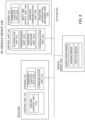
- FIG. 2 is a view for explaining component elements included in the vehicle 10 according to the present embodiment.
- the vehicle 10 according to the present embodiment is configured to include an in-vehicle device 100, a plurality of ECUs 120, and a sensor group 140.
- the vehicle 10 may include a plurality of ECUs that manage different vehicle components.
- the plurality of ECUs there can be mentioned, for example, a body ECU, an engine ECU, a hybrid ECU, a powertrain ECU and the like.
- the ECU may be divided on a functional basis. For example, it may be divided into an ECU that performs a security function, an ECU that performs an automatic parking function, and an ECU that performs a remote control function.
- the in-vehicle device 100 is a device that provides information to an occupant of the vehicle (e.g., a car navigation device).
- the in-vehicle device 100 is also referred to as a car navigation device, an infotainment device, or a head unit. With the in-vehicle device 100, it is possible to provide navigation and entertainment to the occupant of the vehicle.
- the in-vehicle device 100 has a function of performing wireless communication with the external network.
- the in-vehicle device 100 may have a function of downloading traffic information, road map information, music, moving images, etc., by communicating with the external network of the vehicle 10.
- in-vehicle device 100 may be a device capable of cooperating with a smartphone or the like.
- the in-vehicle device 100 can be constituted by a computer having a processor such as a CPU, a GPU or the like, a main storage device such as a RAM, a ROM or the like, and an auxiliary storage device such as an EPROM, a hard disk drive, a removable medium or the like.
- An operating system (OS), various programs, various tables, and the like are stored in the auxiliary storage device, and by executing the programs stored therein, it is possible to realize each function that meets a predetermined purpose, as described later.
- OS operating system
- some or all of the functions may be implemented by a hardware circuit such as an ASIC or an FPGA.
- the in-vehicle device 100 is configured to include a control unit 101, a storage 102, a communication unit 103, an input and output unit 104, a wireless communication unit 105, and a position information obtaining unit 106.
- the control unit 101 is an arithmetic unit that realizes the various functions of the in-vehicle device 100 by executing a predetermined program.
- the control unit 101 may be implemented by a CPU or the like, for example.
- the control unit 101 is configured to include three functional modules: a determination unit 1011, a transmission unit 1012, and a function providing unit 1013. Each functional module may be implemented by executing a stored program by the CPU.
- the determination unit 1011 determines whether or not the operating conditions for each a plurality of driving support functions provided by the ECU 120 are established.
- the determination unit 1011 obtains control data for controlling the vehicle 10 and sensor data generated by sensors mounted on the vehicle via a bus of an in-vehicle network to be described later, for example, and determines whether or not the operating conditions are established.
- the determination unit 1011 may notify the driver to that effect.
- a notification can be made, for example, through an indicator lamp or a display provided in the driver's seat.
- FIG. 3 is a table illustrating a plurality of driving support functions and their operating conditions. For example, in the illustrated example, the use of a driving support function "snow mode" becomes available when the following conditions are satisfied.
- a list of such operating conditions is held as operating condition data by both the ECU 120 and the in-vehicle device 100.
- the in-vehicle device 100 i.e., the determination unit 1011 compares such data with sensor data and the like obtained via the in-vehicle network to determine that the operating conditions for a driving support function have been established. The result of the determination is sent to the transmission unit 1012.
- Transmission unit 1012 generates data relating to the state of vehicle 10 (hereinafter, referred to as vehicle data), and periodically transmits the data to server device 200.
- vehicle data includes data relating to the travel of the vehicle and the result of determinations made by the determination unit 1011.
- FIG. 4 illustrates an example of the vehicle data generated by the transmission unit 1012.
- a vehicle ID is an identifier for uniquely identifying a target vehicle 10.
- Position information is information that indicates the position (latitude, longitude) of a point at which the vehicle data was generated.
- Travel data is data relating to the travel of the vehicle 10.
- the travel data there can be mentioned, for example, the speed of the vehicle 10, the direction of travel, information on driving operation (e.g., a throttle opening, a steering operation amount, etc.), and the like.
- driving operation e.g., a throttle opening, a steering operation amount, etc.
- Such data can be obtained based on control data and sensor data flowing through the in-vehicle network.
- Reference numeral 401 denotes a field in which the result of the determination performed by the determination unit 1011 is stored.
- an identifier of each driving support function for which its operating conditions are established is stored.
- a point at which the operating conditions for a driving support function were satisfied is referred to as a first point.
- the transmission unit 1012 stores the identifier of the corresponding driving support function in a predetermined field (reference numeral 401) in the vehicle data. In cases where the operating conditions for a plurality of driving support functions are established, a plurality of identifiers are stored in this field. Note, however, that in cases where the operating conditions for any driving support function are not established, no data is stored in this field.
- the vehicle data may include other data relating to the travel of the vehicle 10.
- data there can be mentioned, for example, the speed of the vehicle 10, the direction of travel, information on driving operation (e.g., a throttle opening, a steering operation amount, etc.), and the like.
- the vehicle data can be obtained based on control data and sensor data flowing through the in-vehicle network.
- the function providing unit 1013 performs various functions provided by the in-vehicle device 100.
- the functions provided by the in-vehicle device 100 include the following, for example.
- a terminal e.g., smartphone, etc.
- the storage 102 is a unit for storing information, and is constituted by a storage medium such as a RAM, a magnetic disk, a flash memory or the like.
- the storage 102 stores various programs to be executed by the control unit 101, data to be used by the programs, etc.
- the storage 102 stores the above-described operating condition data (102A).
- the communication unit 103 is a communication interface for connecting the in-vehicle device 100 to a bus of the in-vehicle network.
- the input and output unit 104 is a unit that receives an input operation performed by a user and presents information to the user. Specifically, it is composed of a touch panel with its control unit, and a liquid crystal display with its control unit. The touch panel and the liquid crystal display are composed of one touch panel display in the present embodiment.
- the input and output unit 104 may include a unit configured to output sound (e.g., an amplifier and a speaker), a unit configured to input sound (a microphone), and the like.
- the wireless communication unit 105 includes an antenna and a communication module for performing wireless communication.
- the antenna is an antenna element for inputting and outputting radio or wireless signals.
- the antenna is compatible with mobile communication (e.g., mobile communication such as 3G, LTE, 5G, etc.).
- mobile communication e.g., mobile communication such as 3G, LTE, 5G, etc.
- the antenna may be configured to include a plurality of physical antennas. For example, when mobile communication using radio waves in a high frequency band such as a microwave or a millimeter wave is performed, a plurality of antennas may be arranged in a distributed manner in order to stabilize the communication.
- the communication module is a module for performing mobile communication.
- the position information obtaining unit 106 includes a GPS (Global Positioning System) antenna and a positioning module for measuring position information.
- the GPS antenna is an antenna that receives positioning signals transmitted from positioning satellites (also referred to as GNSS satellites).
- the positioning module is a module that calculates the position information based on the signals received by the GPS antenna.
- the ECU is an electronic control unit that controls components included in the vehicle 10.
- the vehicle 10 may include a plurality of ECUs.
- the plurality of ECUs control components of mutually different systems such as an engine system, an electrical system, a power train system, etc.
- the ECUs each have a function to generate a prescribed message and to periodically transmit and receive the message via the in-vehicle network.
- the ECU 120 is one of the plurality of ECUs.
- the ECU 120 is an electronic control unit that provides a plurality of driving support functions.
- the ECU 120 provides the driving support functions based on the instructions of the driver.
- the ECU 120 may transmit a steering control command, a throttle control command, a power distribution command, or the like to another ECU that controls the vehicle.
- Each of the plurality of driving support functions can be provided when predetermined conditions are satisfied.
- the ECU 120 can be configured as a computer having a processor such as a CPU, a GPU or the like, a main storage device such as a RAM, ROM or the like, and an auxiliary storage device such as an EPROM, a disk drive, a removable medium or the like.
- a processor such as a CPU, a GPU or the like
- main storage device such as a RAM, ROM or the like
- an auxiliary storage device such as an EPROM, a disk drive, a removable medium or the like.
- the ECU 120 is configured to include a control unit 121, a storage 122, and a communication unit 123.
- the control unit 121 is an arithmetic unit that realizes the various functions of the ECU 120 by executing a predetermined program.
- the control unit 121 may be implemented by a CPU or the like, for example.
- the control unit 121 is configured to include a driving support unit 1211 as a functional module.
- the functional module may be realized by executing a stored program by the CPU.
- the driving support unit 1211 provides the driving support functions to the driver of the vehicle 10.
- the driving support functions are provided based on the instructions of the driver. For example, when an operation for activating a predetermined driving support function is performed via a hardware switch, a touch panel, or the like, the driving support unit 1211 determines whether or not operating conditions for this driving support function are established. In addition, when the operating conditions are established, the driving support unit 1211 starts providing the driving support function.
- the operation itself for making the predetermined driving support function valid may be disabled. For example, a menu displayed on the touch panel display may be hidden.
- the driving support unit 1211 provides a driving support function by transmitting, for example, a steering control command, a throttle control command, a power distribution command and the like to another ECU for controlling the vehicle.
- a driving support function may be provided by the in-vehicle device 100.
- the storage 122 is a unit for storing information, and is constituted by a storage medium such as a RAM, a magnetic disk, a flash memory or the like.
- the storage 122 stores various programs to be executed by the control unit 121, data to be used by the programs, etc.
- the storage 122 stores operating condition data 122A similar to that stored in the in-vehicle device 100.
- the communication unit 123 is a communication interface for connecting the ECU 120 to a bus of the in-vehicle network.
- the sensor group 140 is a set of a plurality of sensors included in the vehicle 10.
- the in-vehicle device 100 uses sensor data obtained by the sensors included in the sensor group 140 in order to determine whether or not the operating conditions for the predetermined driving support function are established.
- the sensor group 140 includes sensors that obtain sensor data relating to the driving operation, such as, for example, a vehicle speed sensor for obtaining a vehicle speed, a steering sensor for obtaining a steering operation angle, and a throttle sensor for obtaining a throttle opening.
- the sensor group 140 may include sensors that obtain operations other than driving.
- a sensor there can be mentioned, for example, a sensor for obtaining an operating status of a wiper or a winker (direction indicator).
- sensors for obtaining other elements may be included in the sensor group 140.
- the sensor group 140 may include a temperature sensor and a rainfall sensor.
- the sensor data obtained by each sensor is transmitted to the ECU 120 or the in-vehicle device 100 via a network bus.
- the network bus is a communication bus that constitutes the in-vehicle network. Although one bus is illustrated in this example, the vehicle 10 may have two or more communication buses. A plurality of communication buses may be connected to each other by a gateway that organizes the plurality of communication buses.
- server device 200 Next, the server device 200 will be described.
- the server device 200 collects the vehicle data from the vehicle 10 (i.e., the in-vehicle device 100), and provides information on the past travel of the vehicle 10 to the user terminal 300 based on the vehicle data thus collected. Specifically, the server device 200 generates a map for teaching a point at which a predetermined driving support function was available in the past travel of the vehicle 10, and provides the map to the user terminal 300.
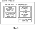
- FIG. 5 is a diagram illustrating in detail the component elements of the server device 200 included in the vehicle system according to the present embodiment.
- the server device 200 can be constituted by a computer having a processor such as a CPU, a GPU or the like, a main storage device such as a RAM, a ROM or the like, and an auxiliary storage device such as an EPROM, a hard disk drive, a removable medium or the like.
- An operating system (OS) various programs, various tables and the like are stored in the auxiliary storage device, so that the programs stored therein are executed by being loaded into a work area of the main storage device, and the component parts and the like are controlled through the execution of the programs, whereby each function meeting a predetermined purpose as described later can be realized.
- OS operating system
- some or all of the functions may be implemented by a hardware circuit such as an ASIC or an FPGA.
- the server device 200 is configured to include a control unit 201, a storage 202, and a communication unit 203.
- the control unit 201 is an arithmetic unit that manages the control performed by the server device 200.
- the control unit 201 can be implemented by an arithmetic processing unit such as a CPU or the like.
- the control unit 201 is configured to include a data collection unit 2011 and an information providing unit 2012 as functional modules. Each functional module may be implemented by executing a stored program by the CPU.
- the data collection unit 2011 performs processing of collecting vehicle data from a plurality of vehicles 10 (i.e., in-vehicle devices 100), and storing the data thus collected in a database.
- a plurality of vehicles 10 i.e., in-vehicle devices 100
- the information providing unit 2012 generates information for supporting the use of a driving support function based on a request from the user terminal 300, and provides the information to the user terminal 300. To be more specific, the information providing unit 2012 generates, for a predetermined driving support function, a map for teaching a point at which the driving support function was available (i.e., a point at which the operating conditions for the driving support function were satisfied), and provides the map to the user terminal 300.
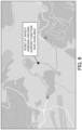
- FIG. 6 illustrates an example of a map representing a travel route of the vehicle 10 (hereinafter, referred to as a route map).
- the information providing unit 2012 refers to the vehicle data of the corresponding vehicle 10, and generates an image by mapping (superimposing) a point (i.e., a first point) where the operating conditions for the driving support function were satisfied on the route map.
- a point i.e., a first point
- the corresponding road section may be mapped on the route map, as illustrated in FIG. 7 .
- the information providing unit 2012 may superimpose, on the route map, text or the like explaining what kind of driving support function was available at the corresponding point or road section.
- the storage 202 is configured to include a main storage device and an auxiliary storage device.
- the main storage device is a memory in which control programs to be executed by the control unit 201 and data to be used by the control programs are developed.
- the auxiliary storage device stores the control programs to be executed in the control unit 201 and data to be used by the control programs.
- the storage 202 stores a vehicle database 202A and a road database 202B.
- the vehicle database 202A is a database that stores vehicle data transmitted from a plurality of in-vehicle devices 100 under the management of the system.
- the vehicle database 202A stores a plurality of vehicle data described with reference to FIG. 4 .
- the road database 202B is a database that stores road map data.
- the data stored in the road database 202B are used when the information providing unit 2012 generates the route map.
- the communication unit 203 is a communication interface for connecting the server device 200 to a network.
- the communication unit 203 is configured to include, for example, a network interface board and a wireless communication interface for wireless communication.
- the user terminal 300 is a computer owned by a user associated with the vehicle 10 (typically, a driver of the vehicle 10).
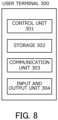
- FIG. 8 illustrates the component elements of the user terminal 300 in more detail.
- the user terminal 300 is configured to include a control unit 301, a storage 302, a communication unit 303, and an input and output unit 304.
- the control unit 301 is an arithmetic unit that manages the control performed by the user terminal 300.
- the control unit 301 can be realized by an arithmetic processing device such as a CPU (Central Processing Unit).
- the control unit 301 performs a function of accessing the server device 200 and interacting with the server device 200. This function may be implemented by dedicated application software that runs on the user terminal 300.
- the control unit 301 performs processing of requesting a route map corresponding to a given vehicle 10 from the server device 200 and processing of outputting the route map received from the server device 200.
- the storage 302 is configured to include a main storage device and an auxiliary storage device.
- the main storage device is a memory in which control programs to be executed by the control unit 301 and data to be used by the control programs are developed.
- the auxiliary storage device stores the control programs to be executed in the control unit 301 and data to be used by the control programs.
- the auxiliary storage device may store programs which are packaged as applications to be executed by the control unit 301.
- the auxiliary storage device may also store an operating system for executing these applications.
- the communication unit 303 is a wireless communication interface for connecting the user terminal 300 to a network.
- the communication unit 303 is configured to be able to communicate with the server device 200 via a wireless LAN or a mobile communication service such as 3G, LTE, 5G or the like.
- the input and output unit 304 is a unit that receives an input operation performed by the user and presents information to the user.
- the input and output unit 304 is composed of, for example, one touch panel display.
- the input and output unit 304 may be composed of a liquid crystal display and its control means, or a touch panel and its control means.
- FIGS. 2 , 5 and 8 are merely examples, and all or part of the functions thus illustrated may be executed by using a circuit designed for exclusive use.
- the programs may be stored or executed by a combination of a main storage device and an auxiliary storage device other than those illustrated in the figure.
- FIG. 9 is a flowchart of the method to be performed by the in-vehicle device 100. The processing illustrated is repeatedly executed at a predetermined cycle while the vehicle 10 is traveling.
- steps S11 to S13 is individually executed for each of the plurality of driving support functions included in the vehicle 10.
- step S11 the determination unit 1011 obtains sensor data.
- the vehicle speed, the outside air temperature, the state of wipers or winkers, drive mode, the operating status of a traction control function or a cruise control function, the history of steering operation, etc. are to be obtained.
- the sensor data can be obtained from sensors included in the sensor group 140 or from a plurality of ECUs provided in the vehicle 10.
- step S12 the determination unit 1011 determines whether or not the operating conditions are satisfied with respect to a target driving support function. The determination can be made based on the sensor data and the operating condition data 102A.
- step S13 the result of the determination performed in step S12 is temporarily stored.
- the identifier of a driving support function for which its operating conditions are satisfied, position information, date and time information, and the like are temporarily stored.
- the determination unit 1011 executes the processing described above for all of the plurality of driving support functions included in the vehicle 10.
- step S14 based on the temporarily stored determination result, the transmission unit 1012 generates vehicle data and transmits it to the server device 200.
- the vehicle data is composed of a plurality of fields.
- the processing illustrated in FIG. 9 is repeatedly executed until the vehicle 10 finishes traveling (e.g., until the ignition is turned off). That is, during a period in which the vehicle 10 is traveling, the vehicle data is periodically generated and sequentially transmitted to the server device 200.
- the vehicle data is received by the server device 200 (i.e., the data collection unit 2011) and stored in the vehicle database 202A.
- the in-vehicle device 100 may execute processing (i.e., initialization processing) of obtaining information on the user and the vehicle from the server device 200.
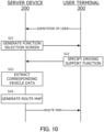
- FIG. 10 is a sequence diagram of processing to be executed by the server device 200 and the user terminal 300.
- the processing is started at the timing when the user terminal 300 (i.e., the control unit 301) activates application software for accessing the server device 200.
- the control unit 301 transmits an identifier of the user to the server device 200.
- the identifier of the user may have been stored in the storage 302 in advance.
- the server device 200 specifies an identifier of the target vehicle 10 based on the identifier of the user received from the user terminal 300.
- step S21 the information providing unit 2012 generates a function selection screen.
- the function selection screen is a screen for selecting any of a plurality of driving support functions available for the vehicle 10.
- the driving support functions available for the vehicle 10 may be obtained based on the vehicle database 202A.
- FIG. 11 illustrates an example of the function selection screen.
- the function selection screen is transmitted to the user terminal 300.
- step S22 the control unit 301 outputs the function selection screen and accepts a selection from the user.
- the user taps any of the buttons (e.g., a reference numeral 1101), a driving support function thus selected is notified to the server device 200.
- step S23 based on the identifier of the vehicle 10 and the driving support function designated by the user, the information providing unit 2012 extracts a record of the corresponding vehicle data from the vehicle database 202A.
- step S24 the information providing unit 2012 generates a user interface screen for presenting a route map to the user.
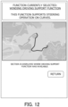
- the information providing unit 2012 generates a graphic for teaching the user about a point or a section where the operating conditions for the driving support function were satisfied, and superimposes the graphic on the route map.
- the graphic may be an icon, a figure, or the like.
- the information providing unit 2012 determines the point (or road section) at which the operating conditions for the designated driving support function were satisfied, and superimposes the graphic representing the point (or road section) on the route map.
- FIG. 12 is an example of an image in which a graphic showing a section in which the operating conditions for the designated driving support function were satisfied is superimposed on the route map.
- the vehicle system periodically determines whether or not each of a plurality of vehicles 10 has satisfied the operating conditions for a predetermined driving support function, and notifies the result of the determination together with the position information thereof to the server device 200.
- the server device 200 informs a user of the points at which the operating conditions for the driving support function were satisfied. As a result, it becomes possible for the user to grasp the points at which the operating conditions for each driving support function were satisfied after the fact.
- the in-vehicle device 100 notifies in real time that the operating conditions for a driving support function are satisfied, while the vehicle is traveling. In such a form, it is not necessary to reissue similar notifications that have already been made.
- the server device 200 determines whether or not to make an ex-post notification for each point.
- the in-vehicle device 100 when the operating conditions for a driving support function have been satisfied while the vehicle 10 is traveling, the in-vehicle device 100 notifies the user (i.e., the driver) in real time under a certain condition. In addition, an ex-post notification is omitted for a point at which a notification was made during the travel of the vehicle.
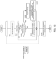
- FIG. 13 is a flowchart of processing to be executed by the in-vehicle device 100 in the second embodiment. Note that the same processing as in the first embodiment is indicated by a dotted line, and a detailed description thereof is omitted.
- the determination unit 1011 determines whether or not the notification condition is satisfied (step S12A).
- the notification condition is a condition for notifying the driver that a driving support function is available while the vehicle is traveling. For example, if a notification is made while the winkers are operating or when the inter-vehicle distance between the subject vehicle and the preceding vehicle is not sufficient, the attention of the driver may be distracted. In this step, it is determined whether or not the vehicle 10 is in such a situation. Note that data relating to the notification condition may have been stored in the storage 102.
- step S13A the determination unit 1011 temporarily stores the determination result.
- step S12B the determination unit 1011 outputs, via the input and output unit 104, a notification to the effect that the corresponding driving support function can be used.
- step S13B the determination result is temporarily stored in association with a notification flag.
- the notification flag is a flag indicating the presence or absence of a notification during travel.
- the notification flag is added to the vehicle data.
- FIG. 14 illustrates an example of the vehicle data in the second embodiment.
- the notification flag i.e., reference numeral 1401
- the transmission unit 1012 generates vehicle data including such a flag.
- step S24 the server device 200 (i.e., the information providing unit 2012) performs mapping to the route map only for a point(s) (or a road section(s)) at which the notification has not been made while the vehicle is traveling. In other words, the mapping is omitted for the first point at which the notification flag is set.
- a notification is not made in the vehicle when the notification condition is not satisfied, but in such a case, a notification may be temporarily suspended so that it may be output at the timing when the notification condition is satisfied (e.g., at the timing when a lane change is completed).
- FIG. 15 is a flowchart of processing to be executed by the in-vehicle device 100 in the third embodiment. Note that the same processing as in the first embodiment is indicated by a dotted line, and a detailed description thereof is omitted.
- step S12 when the determination is affirmative in step S12, the determination unit 1011 determines whether or not the corresponding driving support function is currently being used (step S12C).
- step S13A the determination unit 1011 temporarily stores the determination result.
- step S13C the determination unit 1011 temporarily stores the determination result in association with a use flag.
- the use flag is a flag indicating whether or not the corresponding driving support function has been used while the vehicle is traveling.
- the notification flag (i.e., reference numeral 1401) in the second embodiment is replaced by the use flag.
- the use flag when the use flag is set, it means that the corresponding driving support function has been used at the corresponding point.
- step S24 the server device 200 (i.e., the information providing unit 2012) performs mapping to the route map only for the driving support functions that were not used during the travel of the vehicle. In other words, the mapping is omitted for the first point at which the use flag is set.
- the in-vehicle device 100 may generate vehicle data and transmits it to the server device 200, but the role of the server device 200 may be given to the in-vehicle device 100.
- the in-vehicle device 100 may generate a route map and transmit it to the user terminal 300.
- the server device 200 teaches a user a point or section where the operating conditions were satisfied for a driving support function designated by the user, but a point or section where ex-post teaching is not needed may be omitted.
- the driving support function can be excluded from teaching.
- the storage 202 may store data that associates the user with the driving support functions to be taught (or to be excluded from teaching).
- processing described as being performed by one device may be shared and executed by a plurality of devices.
- processing described as being performed by different devices may be executed by one device.
- what hardware configuration (server configuration) realizes each function can be flexibly changed.
- a computer program including the functions described in the above embodiments to a computer and causing one or more processors included in the computer to read and execute the program.
- Such a computer program may be provided to the computer by a non-transitory computer-readable storage medium connectable to a system bus of the computer, or may be provided to the computer via a network.
- non-transitory computer readable storage media include: any type of disk such as a magnetic disk (floppy (registered trademark) disk, hard disk drive (HDD), etc.), an optical disk (CD-ROM, DVD disk, Blu-ray disk, etc.); and any type of medium suitable for storing electronic instructions, such as read-only memory (ROM), random access memory (RAM), EPROM, EEPROM, magnetic cards, flash memory, and optical cards.
- ROM read-only memory
- RAM random access memory
- EPROM EPROM
- EEPROM electrically erasable programmable read-only memory
Landscapes
- Engineering & Computer Science (AREA)
- Automation & Control Theory (AREA)
- Mechanical Engineering (AREA)
- Transportation (AREA)
- Human Computer Interaction (AREA)
- Radar, Positioning & Navigation (AREA)
- Remote Sensing (AREA)
- Physics & Mathematics (AREA)
- General Physics & Mathematics (AREA)
- Health & Medical Sciences (AREA)
- Computing Systems (AREA)
- General Health & Medical Sciences (AREA)
- Medical Informatics (AREA)
- Computer Networks & Wireless Communication (AREA)
- Signal Processing (AREA)
- Traffic Control Systems (AREA)
- Navigation (AREA)
Claims (13)
- Appareil de traitement de l'information (200) configuré pour être monté sur un premier véhicule (10), comprenant une unité de commande (201) comprenant au moins un processeur configuré pour exécuter :l'obtention, à partir du premier véhicule (10), de données de véhicule se rapportant à un déplacement du premier véhicule (10) ; etl'identification, sur la base des données de véhicule, de un ou plusieurs premiers points, qui sont un ou plusieurs points où le premier véhicule (10) a satisfait des conditions de fonctionnement pour une fonction d'aide à la conduite prédéterminée incluse dans le premier véhicule (10) alors que le premier véhicule (10) se déplace ;l'appareil de traitement de l'information (200) étant caractérisé en ce que l'unité de commande (201) est configurée pour apprendre les un ou plusieurs premiers points à un utilisateur associé au premier véhicule (10).
- Appareil de traitement de l'information (200) selon la revendication 2, dans lequel
l'unité de commande (201) est configurée pour générer une carte dans laquelle les un ou plusieurs premiers points sont reportés sur un itinéraire de déplacement passé du premier véhicule (10). - Appareil de traitement de l'information (200) selon la revendication 2, dans lequel
les données de véhicule indiquent un état de satisfaction des conditions de fonctionnement pour la fonction d'aide à la conduite pour chaque point. - Appareil de traitement de l'information (200) selon la revendication 2, dans lequel
l'unité de commande (201) est configurée pour extraire un deuxième point satisfaisant une condition prédéterminée à partir des un ou plusieurs premiers points, et pour établir le deuxième point comme cible pour la cartographie. - Appareil de traitement de l'information (200) selon la revendication 4, dans lequelle premier véhicule (10) est un véhicule capable de notifier à l'utilisateur que les conditions de fonctionnement pour la fonction d'aide à la conduite ont été satisfaites alors que le véhicule se déplace ; etle deuxième point est un point où la notification n'a pas été faite à l'utilisateur alors que le premier véhicule (10) se déplace, et éventuellement dans lequelles données de véhicule indiquent une présence ou une absence de la notification pour chaque point.
- Appareil de traitement de l'information (200) selon la revendication 4, dans lequelle deuxième point est un point où une fonction d'aide à la conduite correspondante n'a pas été utilisée quand le premier véhicule (10) se déplace, et éventuellement dans lequelles données de véhicule indiquent un état d'utilisation de la fonction d'aide à la conduite pour chaque point.
- Système de véhicule comprenant un dispositif embarqué (100) configuré pour être monté sur un premier véhicule (10) et un dispositif de serveur (200), dans lequelle dispositif embarqué (100) a une première unité de commande (101) configurée pour transmettre au dispositif de serveur (200) des données de véhicule, qui sont des données se rapportant à un déplacement du premier véhicule (10) ; etle dispositif de serveur (200) a une deuxième unité de commande (201) configurée pour identifier, sur la base des données de véhicule obtenues à partir du dispositif embarqué (100), un ou plusieurs premiers points, qui sont un ou plusieurs points où le premier véhicule (10) a satisfait des conditions de fonctionnement pour une fonction d'aide à la conduite prédéterminée alors que le premier véhicule (10) se déplace ;le système de véhicule étant caractérisé en ce que la deuxième unité de commande (201) est configurée pour apprendre les un ou plusieurs premiers points à un utilisateur associé au premier véhicule (10).
- Système de véhicule selon la revendication 7, dans lequel
la deuxième unité de commande (201) est configurée pour générer une carte dans laquelle les un ou plusieurs premiers points sont reportés sur un itinéraire de déplacement passé du premier véhicule (10). - Système de véhicule selon la revendication 8, dans lequel
les données de véhicule indiquent un état de satisfaction des conditions de fonctionnement pour la fonction d'aide à la conduite pour chaque point. - Système de véhicule selon la revendication 8, dans lequel
la deuxième unité de commande (201) est configurée pour extraire un deuxième point satisfaisant une condition prédéterminée à partir des un ou plusieurs premiers points, et pour établir le deuxième point comme cible pour la cartographie. - Système de véhicule selon la revendication 10, dans lequelle premier véhicule (10) est un véhicule capable de notifier à l'utilisateur que les conditions de fonctionnement pour la fonction d'aide à la conduite ont été satisfaites alors que le véhicule se déplace ; etle deuxième point est un point où la notification n'a pas été faite à l'utilisateur alors que le premier véhicule (10) se déplace, et éventuellement dans lequelles données de véhicule indiquent une présence ou une absence de la notification pour chaque point.
- Système de véhicule selon la revendication 10, dans lequelle deuxième point est un point où une fonction d'aide à la conduite correspondante n'a pas été utilisée quand le premier véhicule (10) se déplace, et éventuellement dans lequelles données de véhicule indiquent un état d'utilisation de la fonction d'aide à la conduite pour chaque point.
- Procédé de traitement de l'information comprenant :une étape d'obtention, à partir d'un premier véhicule (10), de données de véhicule se rapportant à un déplacement du premier véhicule (10) ; etune étape d'identification, sur la base des données de véhicule, de un ou plusieurs premiers points, qui sont un ou plusieurs points où le premier véhicule (10) a satisfait des conditions de fonctionnement pour une fonction d'aide à la conduite prédéterminée incluse dans le premier véhicule (10) alors que le premier véhicule (10) se déplace ;le procédé de traitement de l'information étant caractérisé en ce qu'il comprend une étape d'apprentissage des un ou plusieurs premiers points à un utilisateur associé au premier véhicule (10).
Applications Claiming Priority (1)
| Application Number | Priority Date | Filing Date | Title |
|---|---|---|---|
| JP2021208621A JP7582174B2 (ja) | 2021-12-22 | 2021-12-22 | 情報処理装置、車両システム、および情報処理方法 |
Publications (2)
| Publication Number | Publication Date |
|---|---|
| EP4201775A1 EP4201775A1 (fr) | 2023-06-28 |
| EP4201775B1 true EP4201775B1 (fr) | 2024-09-25 |
Family
ID=84569446
Family Applications (1)
| Application Number | Title | Priority Date | Filing Date |
|---|---|---|---|
| EP22216177.0A Active EP4201775B1 (fr) | 2021-12-22 | 2022-12-22 | Appareil de traitement d'informations, système de véhicule et procédé de traitement d'informations |
Country Status (4)
| Country | Link |
|---|---|
| US (1) | US20230192109A1 (fr) |
| EP (1) | EP4201775B1 (fr) |
| JP (1) | JP7582174B2 (fr) |
| CN (1) | CN116331127A (fr) |
Family Cites Families (15)
| Publication number | Priority date | Publication date | Assignee | Title |
|---|---|---|---|---|
| JP4807421B2 (ja) | 2009-03-04 | 2011-11-02 | 株式会社デンソー | 車載用報知装置 |
| JP6348357B2 (ja) * | 2014-07-09 | 2018-06-27 | 株式会社デンソーテン | 情報提供装置、通信システム及び情報提供方法 |
| US9189897B1 (en) * | 2014-07-28 | 2015-11-17 | Here Global B.V. | Personalized driving ranking and alerting |
| JP6532709B2 (ja) | 2015-03-09 | 2019-06-19 | アイシン・エィ・ダブリュ株式会社 | 走行支援システム、方法およびプログラム |
| WO2016151750A1 (fr) * | 2015-03-24 | 2016-09-29 | パイオニア株式会社 | Dispositif de mémorisation d'informations de carte, dispositif de commande de conduite automatique, procédé de commande, programme et support d'informations |
| US9767687B2 (en) * | 2015-09-11 | 2017-09-19 | Sony Corporation | System and method for driving assistance along a path |
| US10315665B2 (en) * | 2016-01-29 | 2019-06-11 | Faraday & Future Inc. | System and method for driver pattern recognition, identification, and prediction |
| JP6493282B2 (ja) * | 2016-04-14 | 2019-04-03 | トヨタ自動車株式会社 | サーバー及び情報提供装置 |
| JP6418199B2 (ja) * | 2016-04-27 | 2018-11-07 | トヨタ自動車株式会社 | 車両の自動運転システム |
| JP2019158648A (ja) * | 2018-03-14 | 2019-09-19 | トヨタ自動車株式会社 | 運転支援装置、制御方法、及びプログラム |
| DE102019102924A1 (de) * | 2019-02-06 | 2020-08-06 | Bayerische Motoren Werke Aktiengesellschaft | Verfahren, Vorrichtung, Computerprogramm und Computerprogrammprodukt zum Betreiben einer Fahrerassistenzfunktion eines Fahrzeuges |
| US12078993B2 (en) * | 2019-05-09 | 2024-09-03 | ANI Technologies Private Limited | Generation of autonomy map for autonomous vehicle |
| DE102019216746A1 (de) * | 2019-10-30 | 2021-05-06 | Zf Active Safety Gmbh | Verfahren zum assistierten Betreiben eines Fahrzeugs, Verfahren zum Bereitstellen eines Assistenzsystemparameters, Fahrerassistenzsystem und System |
| JP7414490B2 (ja) | 2019-11-27 | 2024-01-16 | 株式会社Subaru | 制御装置 |
| JP7365563B2 (ja) | 2019-12-16 | 2023-10-20 | トヨタ自動車株式会社 | 運転支援制御装置 |
-
2021
- 2021-12-22 JP JP2021208621A patent/JP7582174B2/ja active Active
-
2022
- 2022-12-08 US US18/063,230 patent/US20230192109A1/en active Pending
- 2022-12-14 CN CN202211606004.5A patent/CN116331127A/zh active Pending
- 2022-12-22 EP EP22216177.0A patent/EP4201775B1/fr active Active
Also Published As
| Publication number | Publication date |
|---|---|
| JP2023093162A (ja) | 2023-07-04 |
| CN116331127A (zh) | 2023-06-27 |
| US20230192109A1 (en) | 2023-06-22 |
| EP4201775A1 (fr) | 2023-06-28 |
| JP7582174B2 (ja) | 2024-11-13 |
Similar Documents
| Publication | Publication Date | Title |
|---|---|---|
| CN109995631B (zh) | 具有域控制功能的车载控制系统及方法 | |
| US10488868B2 (en) | Dynamic feature availability mapping for a vehicle | |
| US9057624B2 (en) | System and method for vehicle navigation with multiple abstraction layers | |
| JP6493282B2 (ja) | サーバー及び情報提供装置 | |
| US20220107198A1 (en) | First vehicle, second vehicle, vehicle control device, and vehicle control system | |
| US20200377126A1 (en) | Information output control device and information output control method | |
| US8618951B2 (en) | Traffic control database and distribution system | |
| CN111447590A (zh) | 车辆对车辆文件共享系统和方法 | |
| EP4273834A1 (fr) | Dispositif de traitement d'informations, procédé de traitement d'informations, programme, dispositif mobile et système de traitement d'informations | |
| US9014980B2 (en) | Vehicular navigation apparatus | |
| US20240253670A1 (en) | Autonomous driving control device | |
| US12466402B2 (en) | Follow-up travel support device, follow-up travel support method and non transitory recording medium | |
| EP4197873B1 (fr) | Appareil et procédé de traitement d'informations | |
| CN116627081A (zh) | 车辆功能配置方法、装置、车辆、介质及芯片 | |
| EP4201775B1 (fr) | Appareil de traitement d'informations, système de véhicule et procédé de traitement d'informations | |
| JPWO2018179090A1 (ja) | 車両を制御する制御装置、車両を制御する方法、及びプログラム | |
| JP2021130450A (ja) | Hmi制御装置、hmi制御方法、およびhmi制御プログラム | |
| US12583485B2 (en) | Driving assistance device, driving assistance method, and non-transitory computer readable medium storing driving assistance program | |
| CN119585709A (zh) | 一种升级方法及系统 | |
| US20240194007A1 (en) | Information processing apparatus and information processing method | |
| US20240083459A1 (en) | Vehicle control device and vehicle control method | |
| US12428015B2 (en) | Information notification device, information notification method and non-transitory recording medium | |
| CN117677558A (zh) | 控制装置 | |
| CN117141477A (zh) | 一种基于绿波车速控车的方法、装置和车辆 | |
| JP2026004845A (ja) | 車両用情報通信システム |
Legal Events
| Date | Code | Title | Description |
|---|---|---|---|
| PUAI | Public reference made under article 153(3) epc to a published international application that has entered the european phase |
Free format text: ORIGINAL CODE: 0009012 |
|
| STAA | Information on the status of an ep patent application or granted ep patent |
Free format text: STATUS: REQUEST FOR EXAMINATION WAS MADE |
|
| 17P | Request for examination filed |
Effective date: 20221222 |
|
| AK | Designated contracting states |
Kind code of ref document: A1 Designated state(s): AL AT BE BG CH CY CZ DE DK EE ES FI FR GB GR HR HU IE IS IT LI LT LU LV MC ME MK MT NL NO PL PT RO RS SE SI SK SM TR |
|
| GRAP | Despatch of communication of intention to grant a patent |
Free format text: ORIGINAL CODE: EPIDOSNIGR1 |
|
| STAA | Information on the status of an ep patent application or granted ep patent |
Free format text: STATUS: GRANT OF PATENT IS INTENDED |
|
| INTG | Intention to grant announced |
Effective date: 20240430 |
|
| GRAS | Grant fee paid |
Free format text: ORIGINAL CODE: EPIDOSNIGR3 |
|
| GRAA | (expected) grant |
Free format text: ORIGINAL CODE: 0009210 |
|
| STAA | Information on the status of an ep patent application or granted ep patent |
Free format text: STATUS: THE PATENT HAS BEEN GRANTED |
|
| AK | Designated contracting states |
Kind code of ref document: B1 Designated state(s): AL AT BE BG CH CY CZ DE DK EE ES FI FR GB GR HR HU IE IS IT LI LT LU LV MC ME MK MT NL NO PL PT RO RS SE SI SK SM TR |
|
| REG | Reference to a national code |
Ref country code: GB Ref legal event code: FG4D |
|
| REG | Reference to a national code |
Ref country code: CH Ref legal event code: EP |
|
| REG | Reference to a national code |
Ref country code: DE Ref legal event code: R096 Ref document number: 602022006382 Country of ref document: DE |
|
| REG | Reference to a national code |
Ref country code: IE Ref legal event code: FG4D |
|
| P01 | Opt-out of the competence of the unified patent court (upc) registered |
Free format text: CASE NUMBER: APP_57270/2024 Effective date: 20241019 |
|
| REG | Reference to a national code |
Ref country code: LT Ref legal event code: MG9D |
|
| PG25 | Lapsed in a contracting state [announced via postgrant information from national office to epo] |
Ref country code: NO Free format text: LAPSE BECAUSE OF FAILURE TO SUBMIT A TRANSLATION OF THE DESCRIPTION OR TO PAY THE FEE WITHIN THE PRESCRIBED TIME-LIMIT Effective date: 20241225 |
|
| PG25 | Lapsed in a contracting state [announced via postgrant information from national office to epo] |
Ref country code: GR Free format text: LAPSE BECAUSE OF FAILURE TO SUBMIT A TRANSLATION OF THE DESCRIPTION OR TO PAY THE FEE WITHIN THE PRESCRIBED TIME-LIMIT Effective date: 20241226 Ref country code: FI Free format text: LAPSE BECAUSE OF FAILURE TO SUBMIT A TRANSLATION OF THE DESCRIPTION OR TO PAY THE FEE WITHIN THE PRESCRIBED TIME-LIMIT Effective date: 20240925 |
|
| PG25 | Lapsed in a contracting state [announced via postgrant information from national office to epo] |
Ref country code: BG Free format text: LAPSE BECAUSE OF FAILURE TO SUBMIT A TRANSLATION OF THE DESCRIPTION OR TO PAY THE FEE WITHIN THE PRESCRIBED TIME-LIMIT Effective date: 20240925 |
|
| PG25 | Lapsed in a contracting state [announced via postgrant information from national office to epo] |
Ref country code: LV Free format text: LAPSE BECAUSE OF FAILURE TO SUBMIT A TRANSLATION OF THE DESCRIPTION OR TO PAY THE FEE WITHIN THE PRESCRIBED TIME-LIMIT Effective date: 20240925 |
|
| PG25 | Lapsed in a contracting state [announced via postgrant information from national office to epo] |
Ref country code: RS Free format text: LAPSE BECAUSE OF FAILURE TO SUBMIT A TRANSLATION OF THE DESCRIPTION OR TO PAY THE FEE WITHIN THE PRESCRIBED TIME-LIMIT Effective date: 20241225 |
|
| REG | Reference to a national code |
Ref country code: NL Ref legal event code: MP Effective date: 20240925 |
|
| PG25 | Lapsed in a contracting state [announced via postgrant information from national office to epo] |
Ref country code: RS Free format text: LAPSE BECAUSE OF FAILURE TO SUBMIT A TRANSLATION OF THE DESCRIPTION OR TO PAY THE FEE WITHIN THE PRESCRIBED TIME-LIMIT Effective date: 20241225 Ref country code: NO Free format text: LAPSE BECAUSE OF FAILURE TO SUBMIT A TRANSLATION OF THE DESCRIPTION OR TO PAY THE FEE WITHIN THE PRESCRIBED TIME-LIMIT Effective date: 20241225 Ref country code: LV Free format text: LAPSE BECAUSE OF FAILURE TO SUBMIT A TRANSLATION OF THE DESCRIPTION OR TO PAY THE FEE WITHIN THE PRESCRIBED TIME-LIMIT Effective date: 20240925 Ref country code: GR Free format text: LAPSE BECAUSE OF FAILURE TO SUBMIT A TRANSLATION OF THE DESCRIPTION OR TO PAY THE FEE WITHIN THE PRESCRIBED TIME-LIMIT Effective date: 20241226 Ref country code: FI Free format text: LAPSE BECAUSE OF FAILURE TO SUBMIT A TRANSLATION OF THE DESCRIPTION OR TO PAY THE FEE WITHIN THE PRESCRIBED TIME-LIMIT Effective date: 20240925 Ref country code: BG Free format text: LAPSE BECAUSE OF FAILURE TO SUBMIT A TRANSLATION OF THE DESCRIPTION OR TO PAY THE FEE WITHIN THE PRESCRIBED TIME-LIMIT Effective date: 20240925 |
|
| REG | Reference to a national code |
Ref country code: AT Ref legal event code: MK05 Ref document number: 1726443 Country of ref document: AT Kind code of ref document: T Effective date: 20240925 |
|
| PG25 | Lapsed in a contracting state [announced via postgrant information from national office to epo] |
Ref country code: NL Free format text: LAPSE BECAUSE OF FAILURE TO SUBMIT A TRANSLATION OF THE DESCRIPTION OR TO PAY THE FEE WITHIN THE PRESCRIBED TIME-LIMIT Effective date: 20240925 |
|
| PG25 | Lapsed in a contracting state [announced via postgrant information from national office to epo] |
Ref country code: PT Free format text: LAPSE BECAUSE OF FAILURE TO SUBMIT A TRANSLATION OF THE DESCRIPTION OR TO PAY THE FEE WITHIN THE PRESCRIBED TIME-LIMIT Effective date: 20250127 Ref country code: IS Free format text: LAPSE BECAUSE OF FAILURE TO SUBMIT A TRANSLATION OF THE DESCRIPTION OR TO PAY THE FEE WITHIN THE PRESCRIBED TIME-LIMIT Effective date: 20250125 |
|
| PG25 | Lapsed in a contracting state [announced via postgrant information from national office to epo] |
Ref country code: RO Free format text: LAPSE BECAUSE OF FAILURE TO SUBMIT A TRANSLATION OF THE DESCRIPTION OR TO PAY THE FEE WITHIN THE PRESCRIBED TIME-LIMIT Effective date: 20240925 Ref country code: SM Free format text: LAPSE BECAUSE OF FAILURE TO SUBMIT A TRANSLATION OF THE DESCRIPTION OR TO PAY THE FEE WITHIN THE PRESCRIBED TIME-LIMIT Effective date: 20240925 |
|
| PG25 | Lapsed in a contracting state [announced via postgrant information from national office to epo] |
Ref country code: ES Free format text: LAPSE BECAUSE OF FAILURE TO SUBMIT A TRANSLATION OF THE DESCRIPTION OR TO PAY THE FEE WITHIN THE PRESCRIBED TIME-LIMIT Effective date: 20240925 |
|
| PG25 | Lapsed in a contracting state [announced via postgrant information from national office to epo] |
Ref country code: EE Free format text: LAPSE BECAUSE OF FAILURE TO SUBMIT A TRANSLATION OF THE DESCRIPTION OR TO PAY THE FEE WITHIN THE PRESCRIBED TIME-LIMIT Effective date: 20240925 Ref country code: AT Free format text: LAPSE BECAUSE OF FAILURE TO SUBMIT A TRANSLATION OF THE DESCRIPTION OR TO PAY THE FEE WITHIN THE PRESCRIBED TIME-LIMIT Effective date: 20240925 |
|
| PG25 | Lapsed in a contracting state [announced via postgrant information from national office to epo] |
Ref country code: CZ Free format text: LAPSE BECAUSE OF FAILURE TO SUBMIT A TRANSLATION OF THE DESCRIPTION OR TO PAY THE FEE WITHIN THE PRESCRIBED TIME-LIMIT Effective date: 20240925 Ref country code: PL Free format text: LAPSE BECAUSE OF FAILURE TO SUBMIT A TRANSLATION OF THE DESCRIPTION OR TO PAY THE FEE WITHIN THE PRESCRIBED TIME-LIMIT Effective date: 20240925 |
|
| PG25 | Lapsed in a contracting state [announced via postgrant information from national office to epo] |
Ref country code: SK Free format text: LAPSE BECAUSE OF FAILURE TO SUBMIT A TRANSLATION OF THE DESCRIPTION OR TO PAY THE FEE WITHIN THE PRESCRIBED TIME-LIMIT Effective date: 20240925 Ref country code: IT Free format text: LAPSE BECAUSE OF FAILURE TO SUBMIT A TRANSLATION OF THE DESCRIPTION OR TO PAY THE FEE WITHIN THE PRESCRIBED TIME-LIMIT Effective date: 20240925 |
|
| REG | Reference to a national code |
Ref country code: DE Ref legal event code: R097 Ref document number: 602022006382 Country of ref document: DE |
|
| PG25 | Lapsed in a contracting state [announced via postgrant information from national office to epo] |
Ref country code: MC Free format text: LAPSE BECAUSE OF FAILURE TO SUBMIT A TRANSLATION OF THE DESCRIPTION OR TO PAY THE FEE WITHIN THE PRESCRIBED TIME-LIMIT Effective date: 20240925 |
|
| PG25 | Lapsed in a contracting state [announced via postgrant information from national office to epo] |
Ref country code: DK Free format text: LAPSE BECAUSE OF FAILURE TO SUBMIT A TRANSLATION OF THE DESCRIPTION OR TO PAY THE FEE WITHIN THE PRESCRIBED TIME-LIMIT Effective date: 20240925 |
|
| PLBE | No opposition filed within time limit |
Free format text: ORIGINAL CODE: 0009261 |
|
| STAA | Information on the status of an ep patent application or granted ep patent |
Free format text: STATUS: NO OPPOSITION FILED WITHIN TIME LIMIT |
|
| PG25 | Lapsed in a contracting state [announced via postgrant information from national office to epo] |
Ref country code: LU Free format text: LAPSE BECAUSE OF NON-PAYMENT OF DUE FEES Effective date: 20241222 |
|
| 26N | No opposition filed |
Effective date: 20250626 |
|
| PG25 | Lapsed in a contracting state [announced via postgrant information from national office to epo] |
Ref country code: SE Free format text: LAPSE BECAUSE OF FAILURE TO SUBMIT A TRANSLATION OF THE DESCRIPTION OR TO PAY THE FEE WITHIN THE PRESCRIBED TIME-LIMIT Effective date: 20240925 |
|
| REG | Reference to a national code |
Ref country code: DE Ref legal event code: R084 Ref document number: 602022006382 Country of ref document: DE |
|
| REG | Reference to a national code |
Ref country code: BE Ref legal event code: MM Effective date: 20241231 |
|
| PG25 | Lapsed in a contracting state [announced via postgrant information from national office to epo] |
Ref country code: BE Free format text: LAPSE BECAUSE OF NON-PAYMENT OF DUE FEES Effective date: 20241231 |
|
| PG25 | Lapsed in a contracting state [announced via postgrant information from national office to epo] |
Ref country code: IE Free format text: LAPSE BECAUSE OF NON-PAYMENT OF DUE FEES Effective date: 20241222 |
|
| PGFP | Annual fee paid to national office [announced via postgrant information from national office to epo] |
Ref country code: DE Payment date: 20251028 Year of fee payment: 4 |
|
| PG25 | Lapsed in a contracting state [announced via postgrant information from national office to epo] |
Ref country code: HR Free format text: LAPSE BECAUSE OF FAILURE TO SUBMIT A TRANSLATION OF THE DESCRIPTION OR TO PAY THE FEE WITHIN THE PRESCRIBED TIME-LIMIT Effective date: 20240925 |
|
| PGFP | Annual fee paid to national office [announced via postgrant information from national office to epo] |
Ref country code: FR Payment date: 20251117 Year of fee payment: 4 |
|
| REG | Reference to a national code |
Ref country code: GB Ref legal event code: 746 Effective date: 20260106 |