EP4201791B1 - Dispositif de recouvrement, en particulier dispositif de clapet de chargement - Google Patents
Dispositif de recouvrement, en particulier dispositif de clapet de chargement Download PDFInfo
- Publication number
- EP4201791B1 EP4201791B1 EP22215225.8A EP22215225A EP4201791B1 EP 4201791 B1 EP4201791 B1 EP 4201791B1 EP 22215225 A EP22215225 A EP 22215225A EP 4201791 B1 EP4201791 B1 EP 4201791B1
- Authority
- EP
- European Patent Office
- Prior art keywords
- guide
- lid component
- covering device
- opening
- levers
- Prior art date
- Legal status (The legal status is an assumption and is not a legal conclusion. Google has not performed a legal analysis and makes no representation as to the accuracy of the status listed.)
- Active
Links
Images


Classifications
-
- B—PERFORMING OPERATIONS; TRANSPORTING
- B60—VEHICLES IN GENERAL
- B60K—ARRANGEMENT OR MOUNTING OF PROPULSION UNITS OR OF TRANSMISSIONS IN VEHICLES; ARRANGEMENT OR MOUNTING OF PLURAL DIVERSE PRIME-MOVERS IN VEHICLES; AUXILIARY DRIVES FOR VEHICLES; INSTRUMENTATION OR DASHBOARDS FOR VEHICLES; ARRANGEMENTS IN CONNECTION WITH COOLING, AIR INTAKE, GAS EXHAUST OR FUEL SUPPLY OF PROPULSION UNITS IN VEHICLES
- B60K15/00—Arrangement in connection with fuel supply of combustion engines or other fuel consuming energy converters, e.g. fuel cells; Mounting or construction of fuel tanks
- B60K15/03—Fuel tanks
- B60K15/04—Tank inlets
- B60K15/05—Inlet covers
-
- B—PERFORMING OPERATIONS; TRANSPORTING
- B62—LAND VEHICLES FOR TRAVELLING OTHERWISE THAN ON RAILS
- B62D—MOTOR VEHICLES; TRAILERS
- B62D25/00—Superstructure or monocoque structure sub-units; Parts or details thereof not otherwise provided for
- B62D25/24—Superstructure sub-units with access or drainage openings having movable or removable closures; Sealing means therefor
-
- B—PERFORMING OPERATIONS; TRANSPORTING
- B60—VEHICLES IN GENERAL
- B60K—ARRANGEMENT OR MOUNTING OF PROPULSION UNITS OR OF TRANSMISSIONS IN VEHICLES; ARRANGEMENT OR MOUNTING OF PLURAL DIVERSE PRIME-MOVERS IN VEHICLES; AUXILIARY DRIVES FOR VEHICLES; INSTRUMENTATION OR DASHBOARDS FOR VEHICLES; ARRANGEMENTS IN CONNECTION WITH COOLING, AIR INTAKE, GAS EXHAUST OR FUEL SUPPLY OF PROPULSION UNITS IN VEHICLES
- B60K15/00—Arrangement in connection with fuel supply of combustion engines or other fuel consuming energy converters, e.g. fuel cells; Mounting or construction of fuel tanks
- B60K15/03—Fuel tanks
- B60K15/04—Tank inlets
- B60K15/05—Inlet covers
- B60K2015/0515—Arrangements for closing or opening of inlet cover
- B60K2015/0523—Arrangements for closing or opening of inlet cover with sliding connection to the vehicle body
-
- B—PERFORMING OPERATIONS; TRANSPORTING
- B60—VEHICLES IN GENERAL
- B60K—ARRANGEMENT OR MOUNTING OF PROPULSION UNITS OR OF TRANSMISSIONS IN VEHICLES; ARRANGEMENT OR MOUNTING OF PLURAL DIVERSE PRIME-MOVERS IN VEHICLES; AUXILIARY DRIVES FOR VEHICLES; INSTRUMENTATION OR DASHBOARDS FOR VEHICLES; ARRANGEMENTS IN CONNECTION WITH COOLING, AIR INTAKE, GAS EXHAUST OR FUEL SUPPLY OF PROPULSION UNITS IN VEHICLES
- B60K15/00—Arrangement in connection with fuel supply of combustion engines or other fuel consuming energy converters, e.g. fuel cells; Mounting or construction of fuel tanks
- B60K15/03—Fuel tanks
- B60K15/04—Tank inlets
- B60K15/05—Inlet covers
- B60K2015/0515—Arrangements for closing or opening of inlet cover
- B60K2015/053—Arrangements for closing or opening of inlet cover with hinged connection to the vehicle body
-
- Y—GENERAL TAGGING OF NEW TECHNOLOGICAL DEVELOPMENTS; GENERAL TAGGING OF CROSS-SECTIONAL TECHNOLOGIES SPANNING OVER SEVERAL SECTIONS OF THE IPC; TECHNICAL SUBJECTS COVERED BY FORMER USPC CROSS-REFERENCE ART COLLECTIONS [XRACs] AND DIGESTS
- Y02—TECHNOLOGIES OR APPLICATIONS FOR MITIGATION OR ADAPTATION AGAINST CLIMATE CHANGE
- Y02T—CLIMATE CHANGE MITIGATION TECHNOLOGIES RELATED TO TRANSPORTATION
- Y02T10/00—Road transport of goods or passengers
- Y02T10/60—Other road transportation technologies with climate change mitigation effect
- Y02T10/70—Energy storage systems for electromobility, e.g. batteries
Definitions
- the technology according to the invention relates to a covering device, in particular a loading flap device, with a cover component and a displacement mechanism for the cover component for closing and releasing an opening in a vehicle body according to the type defined in more detail in the preamble of claim 1.
- a displacement mechanism for a movable body part for covering a tank and/or a loading area of a motor vehicle is known.
- the movable body part is a flap that can be lowered relative to a fixed body area into a position that completely exposes the loading area and can be displaced under the fixed body area.
- a double guide rail is provided, in which a first guide rail for lowering the flap is arranged on a control carriage, which itself can move linearly along a guide track fixed to the vehicle.
- This well-known displacement mechanism is structurally complex, has a high number of components and requires a high level of assembly effort.
- the DE 44 40 814 A1 discloses a tank flap that can be moved from a closed position to an open position below the vehicle body.
- guide elements with guide bolts are provided on the tank flap, each of which is accommodated in a guide track with a straight and a curved guide section.
- the curved guide section ensures a lifting movement, while the straight guide section causes a sliding movement.
- the adjustment movement is carried out, for example, via a rod that is coupled to a transmission part. and transmitted to the tank flap via a coupling lever arranged between the transmission part and the guide element.
- This solution is characterized by an undesirably high installation space requirement due to the linear adjustment movement of the rod.
- Displacement mechanisms for tank flaps and the like which are known from practice and are designed to be more space-efficient, often use so-called riser cables or pull-push cables to displace the tank flap between its operating state in which it closes the tank opening and its operating state in which it releases the tank recess.
- a locking device for closing an access opening in a motor vehicle body with a pull-push cable is, for example, described in EN 10 2016 110 869 A1 described.
- riser cables or push-pull cables pose problems if such displacement mechanisms are also located in the wet area of a vehicle.
- an undesirably high level of sealing is required to prevent the riser cables or push-pull cables from becoming dirty and/or icing up.
- riser cables are flocked to reduce operating noise, which impairs the impression of quality.
- flocked riser cables require increased forces and torques to move the riser cables compared to guides fixed to the housing.
- the cover device comprises a cover component for closing and opening an opening in a vehicle body, wherein the opening can be a passage of a vehicle body into a loading or tank recess formed within the vehicle body.
- the cover component can be designed, for example, as a loading flap for vehicles with an electric drive, but in principle a design as a tank flap for vehicles with an internal combustion engine is also conceivable.
- the cover device has a displacement mechanism for the cover component for closing and opening the opening in the vehicle body, wherein the cover component can be displaced or lowered under the adjacent area of the vehicle body.
- Part of the displacement mechanism is a link guide system, via which the cover component is adjustably guided between a position closing the opening and a position opening.
- At least one control element which can be pivoted about a preferably stationary axis of rotation and which is rotatably connected to at least two control levers in coupling areas.
- the coupling areas are spaced apart from the axis of rotation and also from one another.
- Coupling elements connect the control levers to the cover component in a rotatable manner and each engages in a control track of the guide system fixed to the body.
- the control levers are adjusted along the control tracks during a pivoting of the control element in the direction of a position that corresponds to the release position of the cover elements and during a further pivoting of the control element in the direction of a position that corresponds to the closing position of the cover component.
- the control levers actuate the cover component in the opening direction or in the closing direction of the opening.
- the cover device according to the invention is structurally simple and has a small number of components, and also requires little installation space.
- the cover component of the cover device according to the invention experiences a harmonious movement when opening and closing, whereby, particularly in comparison to solutions with a drive via climbing cables or pull-push cables, the control element can be adjusted with lower drive forces and drive torques and at the same time low operating noise.
- the control element can be adjusted with lower drive forces and drive torques and at the same time low operating noise.
- it can be protected against actuating forces acting on the cover element from the outside in the opening direction in the closed position with little construction effort.
- the vertical lifting movement of the cover component can be in the
- the movement of the cover component can initially take place essentially perpendicular to the opening plane of the vehicle body using the link guide system.
- the subsequent adjustment of the cover component into the position that releases the opening can overall represent a pivoting of the cover component around the axis of rotation of the control element.
- Another advantage is that the displacement mechanism with a pivoting control element can also be used in the wet area of a vehicle without complex sealing measures.
- the link guide system expediently has control tracks that are designed to adjust the cover component to a defined extent during a pivoting movement of the pivotable control element. It is thus possible for the cover component to be adjusted during a pivoting movement of the control element, starting from a first pivoting position that the control element has in the closing operating state of the cover component, in the direction of a second pivoting position that the first control element has in the opening-releasing operating state of the cover component, first essentially vertically or normally from a contact position on the adjacent area of the vehicle body in the form of a lifting movement away from this in the direction of the vehicle interior. Following this lowering movement, the cover component can be moved further essentially under the adjacent area of the vehicle body to an extent that releases the opening.
- the latter adjustment of the cover component within the vehicle body can, for example, be carried out upwards, downwards in the vehicle vertical direction, forwards or backwards in the vehicle longitudinal direction or also in the vehicle vertical direction and in the vehicle longitudinal direction.
- control tracks of the link guide system are preferably provided in the form of slotted hole-like perforated tracks fixed to the body.
- the coupling elements are firmly connected to the cover component or firmly connected to the control levers, depending on the respective application, and are rotatably connected to the cover component or rotatably connected to the control levers and are moved in the control tracks during a pivoting movement of the control levers.
- the first sections of the control tracks can extend essentially in the direction of the lifting movement of the cover component away from the opening.
- second sections of the control tracks are connected to the first sections of the control tracks.
- the courses of the second sections are each aligned at an angle to the courses of the first sections of the control tracks.
- control element comprises a first control lever section and a second control lever section, which are firmly connected to one another at the ends and preferably enclose an acute or obtuse angle with one another.
- the control element can, for example, be at least approximately L-shaped.
- the axis of rotation of the control element runs through a free end of the first control lever section.
- the second control lever section of the control element can be rotatably connected to one of the control levers in the region of its free end.
- control element can be rotatably connected to one of the control levers in the connection area of the control lever sections in order to transmit the swivel drive to the cover component via the control levers in a structurally simple manner.
- the operative connection between the rotation axis and the cover component via the control element and the control levers can be designed such that the rotation axis and rotation axes of the control levers, about which the control levers rotate relative to the control lever sections of the control element, and rotation axes of the control levers, about which the control levers rotate relative to the cover element, each lie at least approximately on a straight line or line of force action in the closed position of the cover component.
- control levers and the control lever sections of the control element that are rotatably connected to them are in a so-called extended position relative to one another in the closed position of the cover component.
- cover component is protected against external influences in the closed position by the simultaneous extended position of the upper and lower control levers or guide links in relation to the control element or drive link.
- external influences include, for example, undesired manual manipulations such as manual pressing, manual shifting, but also, for example, forces caused by the air flow around the vehicle body during a journey and the like.
- the simultaneous extended position of the control lever and the control element on the cover element applies a closing force to the cover component and the cover element is held in place with an optional sealing unit. This ensures with little effort that the cover component seals the interior of the vehicle body against the ingress of dirt and moisture when the opening is closed.
- the coupling elements can be designed as cylindrical bolts whose longitudinal axes correspond to the rotation axes of the control levers relative to the cover component.
- the cover component can thus be adjusted in a structurally simple manner with low adjusting forces, since only frictional forces in the contact areas between the coupling elements and the cover component or between the coupling elements and the control levers in this area of the operative connection have to be overcome.
- At least one of the coupling elements can engage in a further control track, which is provided in the area of the cover component or in the area of the control lever connected to it and is preferably designed as a slot-like perforated track. This makes it easy to compensate for manufacturing tolerances and avoid undesirable jamming in the area of the displacement mechanism.
- One control lever can be arranged between the control track and the cover element and can be operatively connected to them via one of the coupling elements.
- the cover component is then connected to the other control lever and the control track via a further coupling element in an area that is arranged between the control track and the control lever.
- the axis of rotation of the control element can run in the vertical direction of the vehicle or in the longitudinal direction of the vehicle in order to use existing installation space within the vehicle body in a simple manner and to be able to integrate the covering device into existing vehicle systems with little design effort.
- the covering device can be arranged in a closed section of the vehicle body, which is designed with a water drain in a lower area in order to avoid undesirable accumulation of water inside the vehicle body.
- a sensor device can also be provided, via which a current location or position of the cover element can be determined.
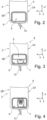
- a vehicle 1 with a vehicle body 2 and a drive device 3 is shown, wherein the drive device can comprise an internal combustion engine, at least one electric machine or also a combination of at least one internal combustion engine and at least one electric machine.
- the vehicle 1 has a covering device 4 with a cover component 5 at the rear, which is intended for closing and opening an opening 6 in the vehicle body 2.
- the opening 6 can be a tank and/or charging recess.
- An electrical plug system can be brought into operative connection through the opening 6 with a corresponding coupling element, which is arranged inside the vehicle body or underneath the outer skin of the vehicle 1, in order to be able to charge an electrical energy storage device of the vehicle 1.
- the cover component 5 then represents either a so-called charging flap, which is essentially designed as a flat or plate-like element.
- Fig.2 is a Fig.1
- the area II is shown, which includes the covering device 4.
- the covering device 4 is in Fig.2 shown in an operating state in which the opening 6 is completely closed by the cover component 5.
- Fig.3 one Fig.2 corresponding representation of the cover device 4 in an operating state in which the opening 6 is partially exposed by the cover component 5 and in which the cover component 5 is partially pivoted upwards in the vehicle vertical direction z within the vehicle body 2.
- the opening 6 is exposed by the cover component 5.
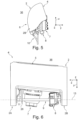
- Fig.5 shows the cover device 4 in a side view, in which a charging plug 7 and the drive unit 8 are shown.
- An electric motor of the drive unit 8 is connected in a manner not shown, for example via a bevel gear or the like, to a Fig.6 operatively connected to the drive shaft 9, which can be seen in more detail.
- the drive unit it is also possible for the drive unit to be driven hydraulically.
- the covering device 4 comprises a water drain 10, via which water or other fluids can be drained downwards in the vertical direction z of the vehicle from the interior of the covering device 4 to the surroundings 36 of the vehicle 1 in a defined manner.
- Fig.7 a rear view of the cover device 4 is shown. From the illustrations according to Fig.6 and Fig.7 It can be seen that the drive shaft 9 extends in the vehicle longitudinal direction x between two lateral body areas 2A and 2B, in each of which parts of a Fig. 8 to Fig. 11 shown in more detail displacement mechanism 11.
- the displacement mechanism 11 comprises two control elements 12, each of which is connected to the drive shaft 9 in a rotationally fixed manner at its end and can be pivoted or rotated together with the drive shaft 9 about a body-fixed axis of rotation 13 by the drive unit 8 in the manner described in more detail below.
- Fig. 8 to Fig. 11 only the control element 12 is shown, which is also referred to below as the drive link.
- the drive link 12 is arranged within the body area 2B.
- the displacement mechanism 11 is designed within the body area 2A to the same extent as in the body area 2B, which will be referred to in the following description.
- Fig. 8 to Fig. 11 referred to in more detail.
- the drive link 12 is essentially L-shaped and comprises two control lever sections 12A and 12B, which are firmly connected to one another at the ends and, in the embodiment shown in more detail in the drawing, essentially form a right angle with one another.
- the rotation axis 13 runs through a free end 12A1 of the first control lever section 12A of the drive link 12.
- the second control lever section 12B is rotatably connected to a control lever 14 in the region of its free end 12B1, which forms a coupling region, which is in a
- the end region 14A facing away from the free end 12B1 of the drive link 12 is rotatably connected to the cover component 5.
- the drive link 12 is rotatably connected to a further control lever 15 in a connection area 12C of the control lever sections 12A and 12B, which also forms a coupling area, which in turn is rotatably connected to the cover component 5 with an end area 15A facing away from the drive link 12.
- the drive link 12 and the lever elements or control levers 14 and 15, which are also referred to below as guide links, are rotatably connected to one another via bolt-like coupling elements 16, 17.
- the guide links 14, 15 are rotatably connected to the cover component 5 via further coupling elements 18, 19 which are firmly connected thereto.
- the coupling elements 18 and 19 additionally engage in control tracks 20, 21 of a link guide system 22 of the covering device 4 and are moved along the control tracks 20 and 21 during pivoting movements of the drive link 12 and the control levers 14, 15 about the axis of rotation 13.
- the control tracks 20 and 21 each have a first section 20A, 21A, which are arranged at an angle to further sections 20B, 21B.
- the control tracks 20, 21 of the slotted guide system 22 are provided in the form of body-fixed slot-like perforated tracks and are designed to move the cover component 5 during a pivoting movement of the drive link 12 starting from its position, which corresponds to the closing position of the cover component and in Fig.9 shown, in the direction of its position, which corresponds to the releasing position of the cover component 5 and which is in Fig. 11 shown, firstly lowered towards the interior of the vehicle from its position on the vehicle body 2 and then moved under the adjacent area of the vehicle body 2.
- the second sections 20B and 21B of the control tracks 20 and 21 each run approximately parallel to the outside of the vehicle body 2 and each have two subsections 20B1, 20B2 and 21B1, 21B2 respectively.
- the subsections 20B1, 20B2 or 21B1, 21B2 again have a straight course and enclose an obtuse angle with each other.
- the second sections of the control tracks can be curved.
- the curvature of the second sections of the control tracks can correspond to the curvature of the outside of the vehicle body 2.
- the first sections 20A, 21A of the control tracks 20, 21 extend essentially in the direction of the lifting movement of the cover component 5 away from the opening 6 in the direction of the interior of the body.
- the second sections 20B, 21B adjoining the first sections 20A, 21A of the control tracks 20, 21 each run at an angle to the courses of the first sections 20A, 21A. This ensures that a pivoting movement of the control element 12 in the direction of its second pivoting position results in the adjusting movement of the cover component 5 following the lifting movement of the cover component 5 under the adjacent area of the vehicle body 2.
- the drive link 12 and the two guide links 14, 15 are each in a so-called extended position.
- This extended position enables the cover component 5 to be held securely in its position closing the opening 6 in a simple manner.
- the cover component 5 is secured against an unwanted lifting movement of the coupling elements 18 and 19 along the first sections 20A, 21A of the control tracks 20, 21 by supporting forces acting on the cover component 5 in the transverse direction of the vehicle along the force action lines F1 and F2 in the area of the drive axle or the rotation axis 13, without imposing a force acting in the opening direction on the drive link or the guide links 14, 15.
- the displacement mechanism 11 has a double over-center position when the opening 6 is closed in order to avoid an unwanted opening of the opening 6 in a structurally simple manner.
- the rotation axes 16A and 17A are each located in the vertical direction z of the vehicle below the force action lines F1 and F2, whereby the cover component 5 only lifts inwards from the vehicle body 2 when the drive link 12 carries out a corresponding pivoting movement.
- the coupling element 18 engages in a further control track 25, which is provided in the area of the cover component 5 and is designed as a slot-like perforated track.
- the further control track 25 makes it possible for the coupling element 18 to be movable both rotationally and translationally relative to the cover component 5 during the opening or closing movement of the cover component 5. This makes it easy to compensate for manufacturing tolerances in the area of the individual components of the cover device 4 with little structural effort and prevents the occurrence of undesirable clamping forces that counteract the movement of the cover component 5.
- the covering device 4 is designed with a sensor device 26, via which a current position of the cover component 5 can be determined.
Landscapes
- Engineering & Computer Science (AREA)
- Chemical & Material Sciences (AREA)
- Combustion & Propulsion (AREA)
- Transportation (AREA)
- Mechanical Engineering (AREA)
- Life Sciences & Earth Sciences (AREA)
- Sustainable Development (AREA)
- Sustainable Energy (AREA)
- Power-Operated Mechanisms For Wings (AREA)
Claims (15)
- Dispositif de couverture (4), en particulier dispositif de couvercle de chargement, avec un élément de couvercle (5) et un mécanisme de déplacement (11) pour le composant de couvercle (5) pour fermer et découvrir une ouverture (6) dans une carrosserie de véhicule (2), dans lequel l'élément de couvercle (5) peut être déplacé sous une zone adjacente de la carrosserie de véhicule (2), et avec un système de guidage de rail (22), par lequel l'élément de couvercle (5) peut être déplacé entre une position fermant l'ouverture (6) et une position découvrant l'ouverture (6), caractérisé en ce qu'il est prévu au moins un élément de guidage (12) povant pivoter autour d'un axe de rotation particulièrement fixe (13) et qu'il est relié de manière opérationnelle à au moins deux leviers de guidage (14, 15) dans des zones de couplage (12C, 12B1) qui sont éloignées de l'axe de rotation (13) et également l'une de l'autre, dans lesquelles des éléments de couplage (18, 19) sont prévus qui relient de manière rotative les leviers de guidage (14, 15) à l'élément de couvercle (5) et qui s'engagent chacun dans un rail de guidage (20, 21), fixé au corps, du système de guidage de rail (22), et dans lequel les leviers de guidage (14, 15) peuvent être déplacés le long des rails de guidage (20, 21) lors d'un pivotement de l'élément de guidage (12) vers une position correspondant à la position de découverte de l'élément de couvercle (5), et lors d'un autre pivotement de l'élément de guidage (12) vers une position correspondant à la position de fermeture de l'élément de couvercle (5), et ainsi actionner l'élément de couvercle (5) dans le sens de l'ouverture ou dans le sens de la fermeture de l'ouverture (6).
- Dispositif de couverture selon la revendication 1,
caractérisé en ce que les rails de guidage (20, 21) sont conçus pour déplacer l'élément de couvercle (5) pendant un mouvement de pivotement de l'élément de guidage (12) à partir de sa position correspondant à la position de fermeture de l'élément de couvercle (5) en direction de sa position correspondant à la position de découverte de l'élément de couvercle (5), en l'abaissant d'abord dans la direction de l'intérieur du véhicule, de préférence verticalement, normalement à partir d'une position de contact, et en le déplaçant ensuite sous la zone adjacente de la carrosserie du véhicule (2). - Dispositif de couverture selon la revendication 1 ou 2,
caractérisé par le fait que les rails de guidage (20, 21) du système de guidage des rails (22) se présentent de préférence sous la forme de rails en forme de fente fixés au corps. - Dispositif de couverture selon l'une des revendications précédentes, caractérisé par le fait que les éléments de couplage (18, 19) sont solidement reliés à l'élément du couvercle (5) ou aux leviers de guidage (14, 15), et reliés de manière rotative à l'élément du couvercle (5) ou aux leviers de guidage (14, 15), et peuvent être déplacés dans les rails de guidage (20, 21) lors d'un mouvement de pivotement du levier de guidage (14, 15).
- Dispositif de couverture selon l'une des revendications précédentes, caractérisé par le fait que les premières sections (20A, 21A) des rails de guidage (20, 21) s'étendent à l'écart de l'ouverture (6) essentiellement dans la direction du mouvement de levage de l'élément de couvercle (5).
- Dispositif de couverture selon l'une des revendications précédentes, caractérisé en ce que les premières sections (20A, 21A) des rails de guidage (20, 21) sont chacune suivies de secondes sections (20B, 21B) des rails de guidage (20, 21), dont les parcours sont chacun à un angle par rapport aux parcours des premières sections (20A, 21A) des rails de guidage (20, 21), de sorte qu'un mouvement de pivotement de l'élément de guidage (12) dans la direction de sa deuxième position de pivotement entraîne le déplacement de l'élément de couvercle (5), à la suite du mouvement de levage, sous la zone adjacente de la carrosserie du véhicule (2).
- Dispositif de couverture selon l'une des revendications précédentes, caractérisé par le fait que l'élément de guidage (12) comprend une première section de levier de guidage (12A) et une deuxième section de levier de guidage (12B), qui sont fermement reliées l'une à l'autre aux extrémités et forment de préférence un angle aigu l'une par rapport à l'autre.
- Dispositif de couverture selon l'une des revendications précédentes, caractérisé par le fait que l'axe de rotation (13) passe par une extrémité libre (12A1) de la première section du levier de guidage (12A), et que la deuxième section du levier de guidage (12B) est, dans la zone de son extrémité libre (12B1), reliée de manière rotative à l'un des leviers de guidage (14).
- Dispositif de couverture selon l'une des revendications précédentes, caractérisé par le fait que l'élément de guidage (12) est, dans la zone de connexion (12C) des sections de levier de guidage (12A, 12B), relié de manière rotative à l'un des leviers de guidage (15).
- Dispositif de couverture selon l'une des revendications précédentes,
caractérisé par le fait que la liaison opérationnelle entre l'axe de rotation (13) et l'élément du couvercle (5) via l'élément de guidage (12) et les leviers de guidage (14, 15) est conçue de manière à ce que l'axe de rotation (13) et les axes de rotation (16A, 17A) des leviers de guidage (14, 15), autour desquels les leviers de guidage (14, 15) tournent par rapport aux sections de levier de guidage (12A, 12B) de l'élément de guidage (12), et les axes de rotation (18A, 19A) des leviers de guidage (14, 15), autour desquels les leviers de guidage (14, 15) tournent par rapport à l'élément de couvercle (5), se situent sur une ligne droite (F1, F2) dans la position fermée de l'élément de couvercle (5). - Dispositif de couverture selon l'une des revendications précédentes,
caractérisé par le fait que les éléments d'accouplement sont conçus comme des boulons cylindriques dont les axes longitudinaux (57A, 58A) correspondent aux axes de rotation des leviers de guidage par rapport à l'élément du couvercle. - Dispositif de couverture selon l'une des revendications précédentes,
caractérisé par le fait qu'au moins un des éléments de couplage (18) s'engage dans un autre rail de guidage (25), qui est prévu dans la zone de l'élément du couvercle (5) ou dans la zone du levier de guidage (15) qui lui est relié, et qui est de préférence conçu comme un rail allongé en forme de fente. - Véhicule (1) avec un dispositif de couverture (4) selon l'une des revendications 1 à 12.
- Véhicule selon la revendication 13,
caractérisé par le fait qu'un mouvement de levage vertical de l'élément de couvercle (5) a lieu essentiellement normalement par rapport au plan de l'ouverture de la carrosserie du véhicule (2), et que le mouvement ultérieur de l'élément de couvercle (5) dans la position découvrant l'ouverture (6) contient un mouvement de rotation et de pivotement de l'élément de couvercle (5) autour de l'axe de rotation (13) de l'élément de guidage (12). - Véhicule selon la revendication 13 ou 14,
caractérisé par le fait que le dispositif de couverture (4) est disposé dans une section fermée de la carrosserie du véhicule (2), qui est conçue avec un drain d'eau (10) dans une zone inférieure.
Applications Claiming Priority (1)
| Application Number | Priority Date | Filing Date | Title |
|---|---|---|---|
| DE102021134396.8A DE102021134396A1 (de) | 2021-12-22 | 2021-12-22 | Abdeckvorrichtung, insbesondere ladeklappenvorrichtung |
Publications (2)
| Publication Number | Publication Date |
|---|---|
| EP4201791A1 EP4201791A1 (fr) | 2023-06-28 |
| EP4201791B1 true EP4201791B1 (fr) | 2024-07-31 |
Family
ID=86498072
Family Applications (1)
| Application Number | Title | Priority Date | Filing Date |
|---|---|---|---|
| EP22215225.8A Active EP4201791B1 (fr) | 2021-12-22 | 2022-12-20 | Dispositif de recouvrement, en particulier dispositif de clapet de chargement |
Country Status (2)
| Country | Link |
|---|---|
| EP (1) | EP4201791B1 (fr) |
| DE (1) | DE102021134396A1 (fr) |
Families Citing this family (4)
| Publication number | Priority date | Publication date | Assignee | Title |
|---|---|---|---|---|
| DE102022120728A1 (de) * | 2022-08-17 | 2024-02-22 | Illinois Tool Works Inc. | Betätigungsmechanismus zum betätigen von abdeckungen für fahrzeuge |
| DE102023116334A1 (de) * | 2023-06-21 | 2024-12-24 | Valmet Automotive Oy | Fahrzeugklappeneinheit mit verlagerungsmechanismus |
| FR3150476A1 (fr) * | 2023-06-28 | 2025-01-03 | Psa Automobiles Sa | Vehicule automobile comportant une trappe d’acces dissimulable |
| PL448332A1 (pl) * | 2024-04-17 | 2025-10-20 | Bos Gmbh & Co. Kg | Urządzenie zamykające dla doku załadunkowego pojazdu mechanicznego |
Family Cites Families (5)
| Publication number | Priority date | Publication date | Assignee | Title |
|---|---|---|---|---|
| DE4440814A1 (de) | 1994-11-15 | 1996-05-23 | Bayerische Motoren Werke Ag | Verschiebbare Klappe, insbesondere Tankklappe eines Kraftfahrzeugs |
| DE102016110869A1 (de) | 2016-06-14 | 2017-12-14 | Dr. Ing. H.C. F. Porsche Aktiengesellschaft | Verschlussvorrichtung zum Verschließen einer Zugriffsöffnung in einer Kraftfahrzeugkarosserie |
| DE102017212397B4 (de) | 2017-07-19 | 2020-09-24 | Bos Gmbh & Co. Kg | Verlagerungsmechanik für ein bewegliches Karosserieteil und Abdeckvorrichtung mit einer solchen Verlagerungsmechanik |
| KR102931329B1 (ko) * | 2020-02-07 | 2026-02-25 | 현대자동차주식회사 | 충전도어 개폐장치 |
| DE202021001685U1 (de) * | 2021-05-07 | 2021-06-04 | sauer product GmbH | Fahrzeugklappe mit Öffnungs- und Schließvorrichtung |
-
2021
- 2021-12-22 DE DE102021134396.8A patent/DE102021134396A1/de active Pending
-
2022
- 2022-12-20 EP EP22215225.8A patent/EP4201791B1/fr active Active
Also Published As
| Publication number | Publication date |
|---|---|
| EP4201791A1 (fr) | 2023-06-28 |
| DE102021134396A1 (de) | 2023-06-22 |
Similar Documents
| Publication | Publication Date | Title |
|---|---|---|
| EP4201791B1 (fr) | Dispositif de recouvrement, en particulier dispositif de clapet de chargement | |
| EP3612695B1 (fr) | Serrure de véhicule automobile | |
| EP4019312B1 (fr) | Dispositif de recouvrement, en particulier dispositif formant volet de chargement, doté d'un composant couvercle permettant de fermer et d'ouvrir une ouverture dans une carrosserie de véhicule | |
| DE102022113349A1 (de) | Ladeschnittstelle für ein fahrzeug, mit einer ladedose, einer fahrzeugklappe und einer antriebsvorrichtung | |
| DE102022107707B3 (de) | Antriebsvorrichtung für eine fahrzeugklappe | |
| DE102020209607B4 (de) | Verschlussanordnung zum Verschließen einer Tankmulde einer Karosserie eines Kraftfahrzeugs | |
| DE102007013517B4 (de) | Betätigungsvorrichtung für ein bewegliches Verkleidungselement, insbesondere Gestängeklappe, und Cabrioletfahrzeug mit einem solchen Verkleidungselement oder einer solchen Gestängeklappe | |
| DE102021111573A1 (de) | Abdeckvorrichtung, insbesondere ladeklappenvorrichtung, mit einer deckelkomponente zum verschliessen und freigeben einer öffnung in einer fahrzeugkarosserie | |
| DE202024100584U1 (de) | Öffnungs- und Schließvorrichtung für ein Kraftfahrzeug | |
| WO2023148331A1 (fr) | Dispositif d'ouverture et de fermeture pour un véhicule automobile | |
| DE102004023614A1 (de) | Vorrichtung zur Abdeckung eines Stauraums eines Kraftfahrzeugs | |
| EP3148826B1 (fr) | Dispositif pourvu d'un couvercle pour toit de véhicule | |
| DE102020134314A1 (de) | Abdeckvorrichtung, insbesondere ladeklappenvorrichtung, mit einer deckelkomponente zum verschliessen und freigeben einer öffnung in einer fahrzeugkarosserie | |
| DE102011015093A1 (de) | Verdeckkastendeckel-Hinterkantenscharnier | |
| DE102023120353B4 (de) | Fahrzeugeinheit eines konduktiven Ladesystems mit einer Hub-Schwenk-Kulisse | |
| EP4206016B1 (fr) | Interface de chargement pour un véhicule, comprenant une boîte de chargement, un hayon de véhicule et un dispositif d'entraînement | |
| DE202024100401U1 (de) | Öffnungs- und Schließvorrichtung für ein Kraftfahrzeug | |
| DE102022105588A1 (de) | Fahrzeug mit einer bewegbaren klappe | |
| EP3183407B1 (fr) | Ensemble charnière pour porte de véhicule automobile | |
| EP4201724B1 (fr) | Véhicule avec un volet mobile | |
| EP2357103A2 (fr) | Verrouillage pour un couvercle pour un véhicule de type cabriolet | |
| DE102008045905A1 (de) | Kraftfahrzeug mit Spindelantrieb zum Bewegen einer Klappe | |
| DE102023111170A1 (de) | Antriebsvorrichtung einer fahrzeugklappeneinheit | |
| DE102024120212B4 (de) | Schließvorrichtung für eine Öffnung eines Kraftfahrzeugs | |
| DE102023114126A1 (de) | Vorrichtung zum verstellen einer fahrzeug-klappeneinheit, insbesondere einer ladeklappeneinheit |
Legal Events
| Date | Code | Title | Description |
|---|---|---|---|
| PUAI | Public reference made under article 153(3) epc to a published international application that has entered the european phase |
Free format text: ORIGINAL CODE: 0009012 |
|
| STAA | Information on the status of an ep patent application or granted ep patent |
Free format text: STATUS: THE APPLICATION HAS BEEN PUBLISHED |
|
| AK | Designated contracting states |
Kind code of ref document: A1 Designated state(s): AL AT BE BG CH CY CZ DE DK EE ES FI FR GB GR HR HU IE IS IT LI LT LU LV MC ME MK MT NL NO PL PT RO RS SE SI SK SM TR |
|
| STAA | Information on the status of an ep patent application or granted ep patent |
Free format text: STATUS: REQUEST FOR EXAMINATION WAS MADE |
|
| 17P | Request for examination filed |
Effective date: 20230821 |
|
| RBV | Designated contracting states (corrected) |
Designated state(s): AL AT BE BG CH CY CZ DE DK EE ES FI FR GB GR HR HU IE IS IT LI LT LU LV MC ME MK MT NL NO PL PT RO RS SE SI SK SM TR |
|
| GRAJ | Information related to disapproval of communication of intention to grant by the applicant or resumption of examination proceedings by the epo deleted |
Free format text: ORIGINAL CODE: EPIDOSDIGR1 |
|
| GRAP | Despatch of communication of intention to grant a patent |
Free format text: ORIGINAL CODE: EPIDOSNIGR1 |
|
| GRAP | Despatch of communication of intention to grant a patent |
Free format text: ORIGINAL CODE: EPIDOSNIGR1 |
|
| STAA | Information on the status of an ep patent application or granted ep patent |
Free format text: STATUS: GRANT OF PATENT IS INTENDED |
|
| INTG | Intention to grant announced |
Effective date: 20240229 |
|
| P01 | Opt-out of the competence of the unified patent court (upc) registered |
Effective date: 20240425 |
|
| GRAS | Grant fee paid |
Free format text: ORIGINAL CODE: EPIDOSNIGR3 |
|
| GRAA | (expected) grant |
Free format text: ORIGINAL CODE: 0009210 |
|
| STAA | Information on the status of an ep patent application or granted ep patent |
Free format text: STATUS: THE PATENT HAS BEEN GRANTED |
|
| AK | Designated contracting states |
Kind code of ref document: B1 Designated state(s): AL AT BE BG CH CY CZ DE DK EE ES FI FR GB GR HR HU IE IS IT LI LT LU LV MC ME MK MT NL NO PL PT RO RS SE SI SK SM TR |
|
| REG | Reference to a national code |
Ref country code: CH Ref legal event code: EP Ref country code: GB Ref legal event code: FG4D Free format text: NOT ENGLISH |
|
| REG | Reference to a national code |
Ref country code: DE Ref legal event code: R096 Ref document number: 502022001360 Country of ref document: DE |
|
| REG | Reference to a national code |
Ref country code: IE Ref legal event code: FG4D Free format text: LANGUAGE OF EP DOCUMENT: GERMAN |
|
| REG | Reference to a national code |
Ref country code: LT Ref legal event code: MG9D |
|
| REG | Reference to a national code |
Ref country code: NL Ref legal event code: MP Effective date: 20240731 |
|
| PG25 | Lapsed in a contracting state [announced via postgrant information from national office to epo] |
Ref country code: PT Free format text: LAPSE BECAUSE OF FAILURE TO SUBMIT A TRANSLATION OF THE DESCRIPTION OR TO PAY THE FEE WITHIN THE PRESCRIBED TIME-LIMIT Effective date: 20241202 |
|
| PG25 | Lapsed in a contracting state [announced via postgrant information from national office to epo] |
Ref country code: PT Free format text: LAPSE BECAUSE OF FAILURE TO SUBMIT A TRANSLATION OF THE DESCRIPTION OR TO PAY THE FEE WITHIN THE PRESCRIBED TIME-LIMIT Effective date: 20241202 |
|
| PG25 | Lapsed in a contracting state [announced via postgrant information from national office to epo] |
Ref country code: NO Free format text: LAPSE BECAUSE OF FAILURE TO SUBMIT A TRANSLATION OF THE DESCRIPTION OR TO PAY THE FEE WITHIN THE PRESCRIBED TIME-LIMIT Effective date: 20241031 |
|
| PG25 | Lapsed in a contracting state [announced via postgrant information from national office to epo] |
Ref country code: GR Free format text: LAPSE BECAUSE OF FAILURE TO SUBMIT A TRANSLATION OF THE DESCRIPTION OR TO PAY THE FEE WITHIN THE PRESCRIBED TIME-LIMIT Effective date: 20241101 Ref country code: FI Free format text: LAPSE BECAUSE OF FAILURE TO SUBMIT A TRANSLATION OF THE DESCRIPTION OR TO PAY THE FEE WITHIN THE PRESCRIBED TIME-LIMIT Effective date: 20240731 Ref country code: NL Free format text: LAPSE BECAUSE OF FAILURE TO SUBMIT A TRANSLATION OF THE DESCRIPTION OR TO PAY THE FEE WITHIN THE PRESCRIBED TIME-LIMIT Effective date: 20240731 Ref country code: PL Free format text: LAPSE BECAUSE OF FAILURE TO SUBMIT A TRANSLATION OF THE DESCRIPTION OR TO PAY THE FEE WITHIN THE PRESCRIBED TIME-LIMIT Effective date: 20240731 |
|
| PG25 | Lapsed in a contracting state [announced via postgrant information from national office to epo] |
Ref country code: BG Free format text: LAPSE BECAUSE OF FAILURE TO SUBMIT A TRANSLATION OF THE DESCRIPTION OR TO PAY THE FEE WITHIN THE PRESCRIBED TIME-LIMIT Effective date: 20240731 |
|
| PG25 | Lapsed in a contracting state [announced via postgrant information from national office to epo] |
Ref country code: LV Free format text: LAPSE BECAUSE OF FAILURE TO SUBMIT A TRANSLATION OF THE DESCRIPTION OR TO PAY THE FEE WITHIN THE PRESCRIBED TIME-LIMIT Effective date: 20240731 |
|
| PG25 | Lapsed in a contracting state [announced via postgrant information from national office to epo] |
Ref country code: IS Free format text: LAPSE BECAUSE OF FAILURE TO SUBMIT A TRANSLATION OF THE DESCRIPTION OR TO PAY THE FEE WITHIN THE PRESCRIBED TIME-LIMIT Effective date: 20241130 |
|
| PG25 | Lapsed in a contracting state [announced via postgrant information from national office to epo] |
Ref country code: HR Free format text: LAPSE BECAUSE OF FAILURE TO SUBMIT A TRANSLATION OF THE DESCRIPTION OR TO PAY THE FEE WITHIN THE PRESCRIBED TIME-LIMIT Effective date: 20240731 |
|
| PG25 | Lapsed in a contracting state [announced via postgrant information from national office to epo] |
Ref country code: RS Free format text: LAPSE BECAUSE OF FAILURE TO SUBMIT A TRANSLATION OF THE DESCRIPTION OR TO PAY THE FEE WITHIN THE PRESCRIBED TIME-LIMIT Effective date: 20241031 Ref country code: ES Free format text: LAPSE BECAUSE OF FAILURE TO SUBMIT A TRANSLATION OF THE DESCRIPTION OR TO PAY THE FEE WITHIN THE PRESCRIBED TIME-LIMIT Effective date: 20240731 |
|
| PG25 | Lapsed in a contracting state [announced via postgrant information from national office to epo] |
Ref country code: RS Free format text: LAPSE BECAUSE OF FAILURE TO SUBMIT A TRANSLATION OF THE DESCRIPTION OR TO PAY THE FEE WITHIN THE PRESCRIBED TIME-LIMIT Effective date: 20241031 Ref country code: PL Free format text: LAPSE BECAUSE OF FAILURE TO SUBMIT A TRANSLATION OF THE DESCRIPTION OR TO PAY THE FEE WITHIN THE PRESCRIBED TIME-LIMIT Effective date: 20240731 Ref country code: NO Free format text: LAPSE BECAUSE OF FAILURE TO SUBMIT A TRANSLATION OF THE DESCRIPTION OR TO PAY THE FEE WITHIN THE PRESCRIBED TIME-LIMIT Effective date: 20241031 Ref country code: NL Free format text: LAPSE BECAUSE OF FAILURE TO SUBMIT A TRANSLATION OF THE DESCRIPTION OR TO PAY THE FEE WITHIN THE PRESCRIBED TIME-LIMIT Effective date: 20240731 Ref country code: LV Free format text: LAPSE BECAUSE OF FAILURE TO SUBMIT A TRANSLATION OF THE DESCRIPTION OR TO PAY THE FEE WITHIN THE PRESCRIBED TIME-LIMIT Effective date: 20240731 Ref country code: IS Free format text: LAPSE BECAUSE OF FAILURE TO SUBMIT A TRANSLATION OF THE DESCRIPTION OR TO PAY THE FEE WITHIN THE PRESCRIBED TIME-LIMIT Effective date: 20241130 Ref country code: HR Free format text: LAPSE BECAUSE OF FAILURE TO SUBMIT A TRANSLATION OF THE DESCRIPTION OR TO PAY THE FEE WITHIN THE PRESCRIBED TIME-LIMIT Effective date: 20240731 Ref country code: GR Free format text: LAPSE BECAUSE OF FAILURE TO SUBMIT A TRANSLATION OF THE DESCRIPTION OR TO PAY THE FEE WITHIN THE PRESCRIBED TIME-LIMIT Effective date: 20241101 Ref country code: FI Free format text: LAPSE BECAUSE OF FAILURE TO SUBMIT A TRANSLATION OF THE DESCRIPTION OR TO PAY THE FEE WITHIN THE PRESCRIBED TIME-LIMIT Effective date: 20240731 Ref country code: ES Free format text: LAPSE BECAUSE OF FAILURE TO SUBMIT A TRANSLATION OF THE DESCRIPTION OR TO PAY THE FEE WITHIN THE PRESCRIBED TIME-LIMIT Effective date: 20240731 Ref country code: BG Free format text: LAPSE BECAUSE OF FAILURE TO SUBMIT A TRANSLATION OF THE DESCRIPTION OR TO PAY THE FEE WITHIN THE PRESCRIBED TIME-LIMIT Effective date: 20240731 |
|
| PG25 | Lapsed in a contracting state [announced via postgrant information from national office to epo] |
Ref country code: DK Free format text: LAPSE BECAUSE OF FAILURE TO SUBMIT A TRANSLATION OF THE DESCRIPTION OR TO PAY THE FEE WITHIN THE PRESCRIBED TIME-LIMIT Effective date: 20240731 Ref country code: SM Free format text: LAPSE BECAUSE OF FAILURE TO SUBMIT A TRANSLATION OF THE DESCRIPTION OR TO PAY THE FEE WITHIN THE PRESCRIBED TIME-LIMIT Effective date: 20240731 Ref country code: RO Free format text: LAPSE BECAUSE OF FAILURE TO SUBMIT A TRANSLATION OF THE DESCRIPTION OR TO PAY THE FEE WITHIN THE PRESCRIBED TIME-LIMIT Effective date: 20240731 |
|
| PG25 | Lapsed in a contracting state [announced via postgrant information from national office to epo] |
Ref country code: EE Free format text: LAPSE BECAUSE OF FAILURE TO SUBMIT A TRANSLATION OF THE DESCRIPTION OR TO PAY THE FEE WITHIN THE PRESCRIBED TIME-LIMIT Effective date: 20240731 |
|
| PG25 | Lapsed in a contracting state [announced via postgrant information from national office to epo] |
Ref country code: CZ Free format text: LAPSE BECAUSE OF FAILURE TO SUBMIT A TRANSLATION OF THE DESCRIPTION OR TO PAY THE FEE WITHIN THE PRESCRIBED TIME-LIMIT Effective date: 20240731 |
|
| PG25 | Lapsed in a contracting state [announced via postgrant information from national office to epo] |
Ref country code: SK Free format text: LAPSE BECAUSE OF FAILURE TO SUBMIT A TRANSLATION OF THE DESCRIPTION OR TO PAY THE FEE WITHIN THE PRESCRIBED TIME-LIMIT Effective date: 20240731 Ref country code: IT Free format text: LAPSE BECAUSE OF FAILURE TO SUBMIT A TRANSLATION OF THE DESCRIPTION OR TO PAY THE FEE WITHIN THE PRESCRIBED TIME-LIMIT Effective date: 20240731 |
|
| REG | Reference to a national code |
Ref country code: DE Ref legal event code: R097 Ref document number: 502022001360 Country of ref document: DE |
|
| PLBE | No opposition filed within time limit |
Free format text: ORIGINAL CODE: 0009261 |
|
| STAA | Information on the status of an ep patent application or granted ep patent |
Free format text: STATUS: NO OPPOSITION FILED WITHIN TIME LIMIT |
|
| PG25 | Lapsed in a contracting state [announced via postgrant information from national office to epo] |
Ref country code: MC Free format text: LAPSE BECAUSE OF FAILURE TO SUBMIT A TRANSLATION OF THE DESCRIPTION OR TO PAY THE FEE WITHIN THE PRESCRIBED TIME-LIMIT Effective date: 20240731 |
|
| 26N | No opposition filed |
Effective date: 20250501 |
|
| REG | Reference to a national code |
Ref country code: DE Ref legal event code: R081 Ref document number: 502022001360 Country of ref document: DE Owner name: VALMET AUTOMOTIVE GMBH, DE Free format text: FORMER OWNER: VALMET AUTOMOTIVE OY, UUSIKAUPUNKI, FI |
|
| PG25 | Lapsed in a contracting state [announced via postgrant information from national office to epo] |
Ref country code: LU Free format text: LAPSE BECAUSE OF NON-PAYMENT OF DUE FEES Effective date: 20241220 |
|
| PG25 | Lapsed in a contracting state [announced via postgrant information from national office to epo] |
Ref country code: SE Free format text: LAPSE BECAUSE OF FAILURE TO SUBMIT A TRANSLATION OF THE DESCRIPTION OR TO PAY THE FEE WITHIN THE PRESCRIBED TIME-LIMIT Effective date: 20240731 |
|
| REG | Reference to a national code |
Ref country code: BE Ref legal event code: MM Effective date: 20241231 |
|
| PG25 | Lapsed in a contracting state [announced via postgrant information from national office to epo] |
Ref country code: BE Free format text: LAPSE BECAUSE OF NON-PAYMENT OF DUE FEES Effective date: 20241231 |
|
| PG25 | Lapsed in a contracting state [announced via postgrant information from national office to epo] |
Ref country code: IE Free format text: LAPSE BECAUSE OF NON-PAYMENT OF DUE FEES Effective date: 20241220 |
|
| PGFP | Annual fee paid to national office [announced via postgrant information from national office to epo] |
Ref country code: AT Payment date: 20260113 Year of fee payment: 4 |
|
| PGFP | Annual fee paid to national office [announced via postgrant information from national office to epo] |
Ref country code: FR Payment date: 20251218 Year of fee payment: 4 |
|
| REG | Reference to a national code |
Ref country code: GB Ref legal event code: 732E Free format text: REGISTERED BETWEEN 20260102 AND 20260107 |
|
| PGFP | Annual fee paid to national office [announced via postgrant information from national office to epo] |
Ref country code: DE Payment date: 20260120 Year of fee payment: 4 |