EP4201816B1 - Druckentlastungstüranordnung mit temperaturbetätigtem schloss - Google Patents
Druckentlastungstüranordnung mit temperaturbetätigtem schloss Download PDFInfo
- Publication number
- EP4201816B1 EP4201816B1 EP22210018.2A EP22210018A EP4201816B1 EP 4201816 B1 EP4201816 B1 EP 4201816B1 EP 22210018 A EP22210018 A EP 22210018A EP 4201816 B1 EP4201816 B1 EP 4201816B1
- Authority
- EP
- European Patent Office
- Prior art keywords
- pressure relief
- latch
- relief door
- lock
- configuration
- Prior art date
- Legal status (The legal status is an assumption and is not a legal conclusion. Google has not performed a legal analysis and makes no representation as to the accuracy of the status listed.)
- Active
Links
Images



Classifications
-
- B—PERFORMING OPERATIONS; TRANSPORTING
- B64—AIRCRAFT; AVIATION; COSMONAUTICS
- B64D—EQUIPMENT FOR FITTING IN OR TO AIRCRAFT; FLIGHT SUITS; PARACHUTES; ARRANGEMENT OR MOUNTING OF POWER PLANTS OR PROPULSION TRANSMISSIONS IN AIRCRAFT
- B64D29/00—Power-plant nacelles, fairings or cowlings
- B64D29/06—Attaching of nacelles, fairings or cowlings
-
- B—PERFORMING OPERATIONS; TRANSPORTING
- B64—AIRCRAFT; AVIATION; COSMONAUTICS
- B64D—EQUIPMENT FOR FITTING IN OR TO AIRCRAFT; FLIGHT SUITS; PARACHUTES; ARRANGEMENT OR MOUNTING OF POWER PLANTS OR PROPULSION TRANSMISSIONS IN AIRCRAFT
- B64D29/00—Power-plant nacelles, fairings or cowlings
- B64D29/08—Inspection panels for power plants
-
- E—FIXED CONSTRUCTIONS
- E05—LOCKS; KEYS; WINDOW OR DOOR FITTINGS; SAFES
- E05B—LOCKS; ACCESSORIES THEREFOR; HANDCUFFS
- E05B51/00—Operating or controlling locks or other fastening devices by other non-mechanical means
- E05B51/005—Operating or controlling locks or other fastening devices by other non-mechanical means by a bimetallic or memory-shape element
-
- B—PERFORMING OPERATIONS; TRANSPORTING
- B64—AIRCRAFT; AVIATION; COSMONAUTICS
- B64C—AEROPLANES; HELICOPTERS
- B64C1/00—Fuselages; Constructional features common to fuselages, wings, stabilising surfaces or the like
- B64C2001/009—Fuselages; Constructional features common to fuselages, wings, stabilising surfaces or the like comprising decompression panels or valves for pressure equalisation in fuselages or floors
Definitions
- the present disclosure generally relates to the field of pressure relief doors and, more particularly, to latches for such pressure relief doors.
- a nacelle for an aircraft propulsion system typically includes an inlet, a fan cowl, a thrust reverser, and an exhaust section.
- the nacelle is typically mounted to a wing or a fuselage of an aircraft via a pylon.
- the nacelle may provide smooth, aerodynamic surfaces for airflow around and into a gas turbine engine located within the nacelle.
- Access doors may be incorporated at different locations on a nacelle to allow for easy and/or quick maintenance access.
- Pressure relief doors may also be incorporated by the nacelle to help reduce the internal pressures in the event of a failed pressurized ducting, which may be located throughout the interior of the nacelle. Some doors may serve as both an access door and a pressure relief door (i.e., a dual purpose door).
- One or more pressure relief latches are typically used to control movement of a pressure relief door from a closed position to an open position.
- a pressure relief door may be disposed in its open position to reduce an increased pressure within the nacelle, for instance due to a burst event, failure of pressurized ducting, or the like.
- a pressure relief latch is disposable in each of a latched configuration (e.g., to retain the corresponding pressure relief door in its closed position) and an unlatched configuration (e.g., to allow the corresponding pressure relief door to move to its open position).
- Pressure relief latches are susceptible to failure in the case of at least a certain temperature increases within the nacelle, for instance due to a fire, engine failure, or the like.
- thermal blanket installations have been utilized to reduce the potential of pressure relief latches being heated by an engine fire or the like to the point where the latch changes to its corresponding unlatched configuration to allow the corresponding pressure relief door to move to its open position.
- US 2020/095806 A1 relates to a pressure relief door assembly which is suitable for use in a compartment of an aircraft engine or auxiliary power unit.
- a pressure relief door assembly is presented herein. Both the configuration of such a pressure relief door assembly (including at least certain individual components/subassemblies thereof) and the operation/assembly/manufacture of such a pressure relief door assembly are within the scope of this Summary.
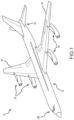
- FIG. 1 A representative aircraft is illustrated in Figure 1 and is identified by reference numeral 10.
- the aircraft 100 includes a fuselage 12, a pair of wings 14, a pair of engines 16 for each wing 14, a vertical stabilizer 18 at an aft end section of the aircraft 10, and a cockpit 20 at forward end section of the aircraft 100.
- Each engine 106 may be mounted to the corresponding wing 14 in any appropriate manner, including using any appropriate pylon.
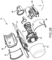
- a nacelle 100 for a propulsion system is illustrated in Figure 2A , in accordance with various embodiments.
- the nacelle 100 may include an inlet 102, a fan cowl 104, a thrust reverser 106, and an exhaust system 108.
- the nacelle 100 may include a pylon 110.
- the pylon 110 may be configured to mount the nacelle 100 and an engine surrounded by nacelle 100 to an aircraft structure, such as a wing (e.g., a wing 14 of the aircraft 10 of Figure 1 ) or aircraft fuselage.
- the propulsion system 112 includes the nacelle 100 and a gas turbine engine 114.
- the gas turbine engine 114 may be surrounded by components of the nacelle 100.
- the nacelle 100 may provide smooth, aerodynamic surfaces for airflow around and into the gas turbine engine 114.
- a fan 116 of the gas turbine engine 114 draws and directs a flow of air into and through the propulsion system 112.
- gas turbine engine 114 is depicted as a turbofan gas turbine engine herein, it should be understood that the concepts described herein are not limited to use with turbofans as the teachings may be applied to other types of turbine engines, including turbojet engines, low-bypass turbofans, high bypass turbofans, or any other gas turbine.
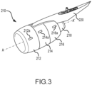
- the nacelle 210 may include an inlet 212, a fan cowl 214, a thrust reverser 216, and an exhaust system 218.
- the inlet 212, fan cowl 214, thrust reverser 216, and exhaust system 218 may be positioned around a central longitudinal axis A-A' of the nacelle 210.
- the nacelle 210 provides smooth aerodynamic surfaces for airflow around and into a gas turbine engine surrounded by the nacelle 210.
- the nacelle 210 may be coupled to a pylon 220.
- the pylon 220 may be configured to mount the nacelle 210 and the gas turbine engine surrounded by nacelle 210 to an aircraft wing (e.g., a wing 14 of the aircraft 10 of Figure 1 ) or aircraft body.
- the nacelle 210 may include one or more doors, such as door 212a, door 214a, and door 216a.
- the inlet 212 may include one or more doors 212a
- the fan cowl 214 may include one or more doors 214a
- the thrust reverser 216 may include one or more doors 216a.
- the doors 212a, 214a, 216a may translate between an open position, wherein an interior of nacelle 210 that is radially inward of the door is exposed, and a closed position, wherein the door contacts and/or forms a sealing interface with the underlying nacelle component (e.g., inlet 212, fan cowl 214 or thrust reverser 216).
- one or more of the doors 212a, 214a, 216a may be a pressure relief door configured to translate to the open position in response to a pressure differential across the door (i.e., the difference between the pressure in the area on the interior of the door and the pressure in the area on the exterior of the door) exceeding a preselected pressure differential.
- a pressure differential across the door i.e., the difference between the pressure in the area on the interior of the door and the pressure in the area on the exterior of the door
- the area on the interior of a door refers to a space or area that is radially inward of the door
- the area on the exterior of a door refers to a space or area that is radially outward of the door.
- One or more of the doors 212a, 214a, 216a could be used by the nacelle 100 of Figures 1-2 .
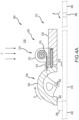
- a pressure relief door assembly is illustrated in Figures 4A-4C and is identified by reference numeral 300.
- Components of the pressure relief door assembly 300 include a pressure relief door 310 and a latch 320 (the latch 320 in turn including a first latch component or latch body 330 and a second latch component or latch bolt 350).
- the pressure relief door 310 is disposable in each of a closed position 312 ( Figure 4A ) and an open position 314 ( Figure 4C ).
- the latch 320 is pressure-actuated and is disposable in each of a latched configuration (so as to retain the pressure relief door 310 in its closed position 312 of Figure 4A ) and an unlatched configuration (so as to allow the pressure relief door 310 to move to its open position 314 of Figure 4C ).
- Figure 4A also shows the latch 320 in its latched configuration
- Figure 4C also shows the latch 320 in its unlatched configuration
- the lock 370 is temperature-actuated and is disposable in each of a locked configuration (so as to retain the pressure relief door 310 in its closed position 312 of Figure 4A , and to also retain the latch 320 in its latched configuration of Figure 4A ) and an unlocked configuration (so as to allow the pressure relief door 310 to move to its open position 314 of Figure 4C when the latch 320 is in its unlatched configuration).
- the pressure relief door 310 includes an interior surface 318 that interfaces with an interior space 316 (e.g., an interior of a nacelle). Both the latch 320 and the lock 370 are disposed within this interior space 316.
- a hinge 308 of any appropriate type movably interconnects (e.g., pivotally) a door frame 302 and the pressure relief door 310.
- One or more hinges 308 may movably interconnect the doorframe 302 and the pressure relief door 310, and each such hinge 308 may be of any appropriate configuration.
- the pressure relief door 310 pivots about the hinge 308 in the direction of the arrow B to change the pressure relief door 310 from its closed position 312 of Figure 4A to its open position 314 of Figure 4C .
- a stop or striker plate 304 may protrude from the door frame 302 for interfacing with the latch 320.
- a perimeter of the door frame 302 defines an opening 306 in which the pressure relief door 310 is disposed when in its closed position 312 of Figure 4A .
- a space is shown between the outer perimeter of the pressure relief door 310 and the inner perimeter of the door frame 302 in Figure 4A for clarity.
- An appropriate seal may be disposed between the door frame 302 and the pressure relief door 310.
- the latch body 330 of the latch 320 may be formed from any appropriate material or combination of materials, and may be mounted to the pressure relief door 310 in any appropriate manner such that the latch body 330 is maintained in a fixed position relative to the pressure relief door 310.
- the latch body 330 includes a bore 332 in the form of a "blind hole,” in that the bore 332 extends from a closed end 334 to a perimeter of the latch body 330.
- a detent 336 is movably disposed within the bore 332 of the latch body 330.
- a free end of the detent 336 that is disposable beyond the perimeter of the latch body 330 may include an enlarged head 338.
- One or more biasing members 340 e.g., a spring 340 is disposed within the bore 332.
- One part of the spring 340 may be maintained in a fixed position relative to the latch body 330 (e.g., by the spring 340 being seated on the closed end 334), while another part of the spring 340 may be maintained in a fixed position relative to the detent 336. In any case, the spring 340 biases the detent 336 in the direction of the latch bolt 350.
- the latch bolt 350 is movable relative to each of the pressure relief door 310 and the latch body 330, and may be movably interconnected with one or more of the pressure relief door 310 and the latch body 330 in any appropriate manner.
- This movable interconnection is shown as a rotational movement in Figure 4A in that the latch bolt 350 is rotatable about a rotational axis 352 in the direction of the arrow A to change the latch 320 from its latched configuration of Figure 4A to its unlatched configuration of Figure 4C .
- the latch bolt 350 may be characterized as having an outer or perimeter wall 354 and a pair of oppositely disposed sidewalls 356 (one such sidewall 356 being shown in Figure 6 , discussed below).
- a detent recess or pocket 358 and a locking recess or pocket 360 are disposed on the perimeter wall 354 of the latch bolt 350.
- the latch bolt 350 further includes a stop 362 that cooperates with the striker plate 304 on the door frame 302 to change the latch 320 from its latched configuration ( Figure 4A ) to its unlatched configuration ( Figure 4C ) such that the pressure relief door 310 may be moved from its closed position 312 ( Figure 4A ) to its open position 314 ( Figure 4C ).
- the lock 370 is maintained in a fixed position relative to each of the latch body 330 and the pressure relief door 310.
- Figures 4A and 4B illustrate the lock 370 being mounted in any appropriate manner to the latch body 330.
- the lock 370 includes a housing 372, which may include an extension 374.
- a bimetallic coil 378 is disposed within the interior of the housing 372, and includes a first metal layer 378a and a second metal layer 378b that are appropriately secured to one another.
- One portion of the bimetallic coil 378 is appropriately secured to an anchor location 380, with the bimetallic coil 378 being "coiled" about this anchor location 380.
- a locking pin 382 is appropriately attached to the bimetallic coil 378, for instance such that the locking pin 382 extends from a free end of the bimetallic coil 378.
- the locking pin 382 is movably disposed in a bore 376 that extends from within the interior of the housing 372 to a perimeter of the housing 372.
- An outer perimeter of the bore 376 may be correspondingly-shaped with an outer perimeter of the locking pin 382.
- the locking pin 382 may move axially relative to the housing 372 in response to expansion or contraction of the bimetallic coil 378.
- the latch 320 is pressure-actuated.
- the head 338 of the detent 336 is disposed in the detent recess 358 of the latch bolt 350 to retain the pressure relief door 310 in the closed position 312 of Figure 4A (the latched configuration for the latch 320).
- the latch 320 will remain in this latched configuration until a pressure threshold within the interior space 316 is satisfied. Satisfaction of the pressure threshold means at least one of: a) that the pressure within the interior space 316 at least one of reaches or exceeds a predetermined pressure; or b) an existence of at least a certain pressure differential across the pressure relief door 310.
- This predetermined pressure is directly proportional to the biasing force exerted by the spring 340, which in turn corresponds with the force that the detent 336 exerts on the latch bolt 350.
- the pressure within the interior space 316 will exert a force on the pressure release door 310 in the direction indicated by the arrows C in Figure 4A (and that will attempt to move the pressure relief door 310 in a counterclockwise direction about the door hinge 308 in the view shown in Figure 4A and represented by the arrow B).
- the force being exerted on the interior surface 318 of the pressure relief door 310 is opposed by the door frame 302 via the engagement between the stop 362 of the latch bolt 350 and the striker plate 304 on the door frame 302.
- the latch bolt 350 When the pressure threshold for the latch 320 is satisfied (e.g., from a burst event), the latch bolt 350 will rotate about the rotational axis 352 (clockwise in the view shown in Figure 4A and represented by the arrow A) and relative to the latch body 330 such that the head 338 of the detent 336 is disposed out of the detent recess 358 of the latch bolt 350 (the unlatched configuration for the latch 320). With the latch 320 now being in this unlatched configuration, the pressure relief door 310 may move from the closed position 312 of Figure 4A to the open position 314 of Figure 4C .
- the lock 370 is temperature-actuated. Disposing the lock 370 in its locked configuration may be characterized as locking the latch 320 in its latched configuration, may be characterized as locking the pressure relief door 310 in its closed position 312, or both.
- the locking pin 382 disposed out of the locking recess 360 of the latch bolt 350 when the lock 370 in its unlocked configuration of Figure 4A .
- the lock 370 will remain in this unlocked configuration until a temperature threshold within the interior space 316 is satisfied. Satisfaction of the temperature threshold means that the temperature within the interior space 316 at least one of reaches or exceeds a predetermined temperature (e.g., due to a fire within the interior space 316).
- the bimetallic coil 378 changes from the contracted configuration shown in Figure 4A to an expanded configuration.
- This expansion of the bimetallic coil 378 produces a corresponding axial movement of the locking pin 382 that disposes the locking pin 382 within the locking recess 360 of the latch bolt 350 (e.g., the locking pin 382 will protrude beyond the housing 372 of the lock 370 at this time).
- the locking pin 382 With the locking pin 382 being disposed within the locking recess 360 of the latch bolt 350 (the locked configuration for the lock 370), the latch bolt 350 is unable to rotate relative to the latch body 330 such that the latch 320 is locked in its latched configuration of Figure 4A .
- the pressure relief door 310 is similarly locked in its closed position 312 of Figure 4A .
- the free end of the locking pin 382 will be spaced further from a reference location (e.g., from a plane that is perpendicular to the locking pin 382 and that extends through the anchor location 380) when the lock 370 is in its locked configuration (again where the locking pin 382 is disposed in the locking recess 360 of the latch bolt 350) compared to its unlocked configuration (where the locking pin 382 is disposed out of the locking recess 360 of the latch bolt 350 - Figure 4A ).
- a reference location e.g., from a plane that is perpendicular to the locking pin 382 and that extends through the anchor location 380
- the locking pin 382 could be entirely disposed within the housing 372 when the lock 370 is in its unlocked configuration, the locking pin 382 could instead protrude beyond the housing 372 when the lock 370 is also in its unlocked configuration (but by a lesser amount compared to when the lock 370 is in its locked configuration).
- a fire within the interior space 316 may cause a temperature increase within the interior space 316 that could satisfy the temperature threshold of the lock 370 (such that the lock 370 is changed from its unlocked configuration to its locked configuration in accordance with the foregoing). At least a certain temperature increase within the interior space 316 may reduce the magnitude of the pressure threshold associated with the latch 320 (such that a reduced pressure within the interior space 316 would change the latch 320 from its latched configuration to its unlatched configuration, to in turn allow the pressure relief door 310 to change from its closed position 312 ( Figure 4A ) to its open position 314 ( Figure 4C ). In the case of a fire, allowing the pressure relief door 310 to move to its open position 314 would provide additional oxygen to support combustion.
- the temperature threshold for the lock 370 may be selected such that the lock 370 changes from its unlocked configuration to its locked configuration with the latch 320 remaining in its latched configuration (which in turn maintains the pressure relief door 310 in its closed position 312) and which may be beneficial in relation to extinguishing a fire within the interior space 316.
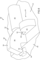
- FIG. 5A-5C illustrate a housing section 390 that includes a pressure relief door assembly 400 (only schematically illustrated in Figure 5A ).
- the housing section 390 may be part of a nacelle for an aircraft.
- the housing section 390 may include a plurality of rails 392 that are spaced from one another along a longitudinal axis and that are disposed about this longitudinal axis.
- the rails 392 may be attached to an outer wall 394 of the housing section 390 in any appropriate manner.
- a support 396 may extend between an adjacent pair of rails 392 to accommodate mounting of the pressure relief door assembly 400 to the housing section 390.
- the pressure relief door assembly 400 includes a door frame 402 (e.g., in accord with the door frame 302 of Figure 4A ), a stop or striker plate 404 (e.g., in accord with the striker plate 304 of Figure 4A ), a pressure relief door 410 (e.g., in accord with the pressure relief door 310 of Figure 4A ), and a latch 420 (e.g., in accord with the latch 320 of Figure 4A ).
- the door frame 402 may be mounted to the support 396 of the housing section 390 in any appropriate manner (e.g., via one or more fasteners such as bolts).
- the latch 420 of the pressure relief door assembly 400 includes a first latch component or latch body 430 (e.g., in accord with the latch body 330 of Figure 4A ) and a second latch component or latch bolt 450 (e.g., in accord with the latch bolt 350 of Figure 4A ).
- the latch bolt 450 is rotatable relative to each of the pressure relief door 410 and the latch body 430 and includes a stop 462 (e.g., in accord with the stop 362 of Figure 4A ).
- the pressure relief door 410 is pivotally interconnected with the door frame 402 by a pair of door hinges 408 (e.g., in accord with the door hinge 308 of Figure 4A ), such that the pressure relief door 410 is rotatable about a hinge axis 406 for rotation relative to the housing section 390 between the closed position of Figure 5A-5C (e.g., in accord with Figure 4A ) and an open position (e.g., in accord with Figure 4C ).
- a lanyard 440 may extend between the door frame 402 and the pressure relief door 410 to provide a limit for the open position of the pressure relief door 410.
- Figure 6 presents a pressure relief door assembly 300' that is a variation of the pressure relief door assembly 300 of Figure 4A (and thus is identified by a "single prime" designation in Figure 6 ).
- the pressure relief door assembly 300' of Figure 6 includes the same general pressure relief door 310, latch 320, and lock 370 of the pressure relief door assembly 300 of Figure 4A .
- the lock 370 is disposed in a different position/orientation in Figure 6 compared to Figure 4A .
- the lock 370 is mounted either directly on the pressure relief door 310 or on a support (not shown) that in turn is mounted directly on the pressure relief door 310. Moreover, when the lock 370 is disposed in its locked configuration, its locking pin 382 extends into a locking recess 360' that intersects with a corresponding sidewall 356 of the latch bolt 350' for the case of the pressure relief door assembly 300' of Figure 6 .
- references to "one embodiment,” “an embodiment,” “various embodiments,” etc. indicate that the embodiment described may include a particular feature, structure, or characteristic, but every embodiment may not necessarily include the particular feature, structure, or characteristic. Moreover, such phrases are not necessarily referring to the same embodiment. Further, when a particular feature, structure, or characteristic is described in connection with an embodiment, it is submitted that it is within the knowledge of one skilled in the art to affect such feature, structure, or characteristic in connection with other embodiments whether or not explicitly described. After reading the description, it will be apparent to one skilled in the relevant art(s) how to implement the disclosure in alternative embodiments.
Landscapes
- Engineering & Computer Science (AREA)
- Aviation & Aerospace Engineering (AREA)
- Special Wing (AREA)
Claims (13)
- Druckentlastungstüranordnung (300; 400), umfassend:eine Druckentlastungstür (310; 410);einen Riegel (320; 420), der einen Riegelkörper (330; 430) und einen Riegelbolzen (350; 450) umfasst;eine Arretierung (336), die bewegbar mit dem Riegelkörper (330; 430) verbunden ist;ein Schloss (370), das eine Bimetallspule (378) und ein Verriegelungselement (382) umfasst, das mit der Bimetallspule (378) verbunden und mit dieser bewegbar ist; wobeider Riegelbolzen (350; 450) relativ zu dem Riegelkörper (330; 430) bewegbar ist, wobei der Riegelbolzen (350; 450) eine mit der Arretierung (336) ausrichtbare Arretierungsaussparung (358) und eine mit dem Verriegelungselement (382) des Schlosses (370) ausrichtbare Verriegelungsaussparung (360) umfasst,wobei sich der Riegel (320; 420) in einer eingeriegelten Konfiguration befindet, wenn sich die Arretierung (336) in der Arretierungsaussparung (358) des Riegelbolzens (350; 450) befindet, und wobei das Schloss (370) in einer verriegelten Konfiguration angeordnet ist, wenn das Verriegelungselement (382) in der Verriegelungsaussparung (360) des Riegelbolzens (350; 450) angeordnet ist,wobei:
das Verriegelungselement (382) als Reaktion darauf, dass die Druckentlastungstüranordnung (300; 400) einer Temperatur ausgesetzt wird, die eine vorbestimmte Temperatur mindestens eines von erreicht oder überschreitet, innerhalb der Verriegelungsaussparung (360) des Riegelbolzens (350; 450) angeordnet wird. - Druckentlastungstüranordnung (300; 400) nach Anspruch 1, wobei das Verriegelungselement (382) außerhalb der Verriegelungsaussparung (360) des Riegelbolzens (350; 450) angeordnet wird, bevor ein Temperaturschwellenwert erreicht wird.
- Druckentlastungstüranordnung (300; 400) nach Anspruch 2, wobei die Erreichung des Temperaturschwellenwerts umfasst, dass die Druckentlastungstüranordnung (300; 400) einer Temperatur ausgesetzt wird, die eine vorbestimmte Temperatur mindestens eines von erreicht oder überschreitet.
- Druckentlastungstüranordnung (300; 400) nach einem der vorhergehenden Ansprüche, ferner umfassend eine entriegelte Konfiguration, in der sich die Bimetallspule (378) in einem zusammengezogenen Zustand befindet und das Verriegelungselement (382) außerhalb der Verriegelungsaussparung (360) des Riegelbolzens (350; 450) angeordnet ist, wobei die verriegelte Konfiguration umfasst, dass sich die Bimetallspule (378) in einem ausgedehnten Zustand befindet.
- Druckentlastungstüranordnung (300; 400) nach einem der vorhergehenden Ansprüche, wobei der Riegelkörper (330; 430) in einer festen Position relativ zu der Druckentlastungstür (310; 410) gehalten wird und der Riegelbolzen (350; 450) relativ zu jedem von dem Riegelkörper (330; 430) und der Druckentlastungstür (310; 410) bewegbar ist.
- Druckentlastungstüranordnung (300; 400) nach Anspruch 5, wobei:
die Druckentlastungstür (310; 410) zwischen der offenen (314) und einer geschlossenen (312) Position bewegbar ist, wobei die Druckentlastungstür (310; 410) in der geschlossenen Position (312) gehalten wird, wenn mindestens eines des Riegels (320; 420) sich in der eingeriegelten Konfiguration befindet und des Schlosses (370) sich in der verriegelten Konfiguration befindet. - Druckentlastungstüranordnung (300; 400) nach Anspruch 6, wobei die Druckentlastungstür (310; 410) in die offene Position (314) bewegbar ist, wenn jedes des Riegels (320; 420) sich in einer ausgeriegelten Konfiguration befindet und des Schlosses (370) sich in einer entriegelten Konfiguration befindet.
- Gondel (100; 210), umfassend die Druckentlastungstüranordnung (300; 400) nach einem der vorhergehenden Ansprüche.
- Verfahren zum Betreiben der Druckentlastungstüranordnung (300; 400) nach einem der vorhergehenden Ansprüche 1-7, wobei die Druckentlastungstür (310; 410) in jeweils einer geschlossenen Position (312) und einer offenen Position (314) angeordnet werden kann, wobei der Riegel (320; 420) in jeweils einer eingeriegelten Konfiguration und einer ausgeriegelten Konfiguration relativ zu der Druckentlastungstür (310; 410) angeordnet werden kann, wobei das Verfahren Folgendes umfasst:Wechseln des Schlosses (370) von einer entriegelten Konfiguration in eine verriegelte Konfiguration als Reaktion darauf, dass die Druckentlastungstüranordnung (300; 400) einer Temperatur ausgesetzt wird, die eine vorbestimmte Temperatur mindestens eines von erreicht oder überschreitet; undHalten der Druckentlastungstür (310; 410) in der geschlossenen Position (312), wobei sich das Schloss (370) in der verriegelten Konfiguration befindet.
- Verfahren nach Anspruch 9, wobei das Wechseln des Schlosses (370) Bewegen des Verriegelungselements (382) des Schlosses (370) in Eingriff mit dem Riegel (320; 420) umfasst, um den Riegel (320; 420) in der eingeriegelten Konfiguration relativ zu der Druckentlastungstür (310; 410) zu halten.
- Verfahren nach Anspruch 9 oder 10, wobei das Wechseln des Schlosses (370) Ausdehnen der Bimetallspule (378) umfasst.
- Verfahren nach Anspruch 11, wobei das Wechseln des Schlosses (370) ferner Bewegen des Verriegelungselements (382) in Eingriff mit dem Riegel (320; 420) umfasst, um den Riegel (320; 420) in der eingeriegelten Konfiguration relativ zu der Druckentlastungstür (310; 410) zu halten, und wobei das Bewegen eines Verriegelungselements (382) als Reaktion auf das Ausdehnen erfolgt.
- Verfahren nach einem der Ansprüche 9 bis 12, ferner umfassend:Erhöhen einer Temperatur, der die Druckentlastungstüranordnung (300; 400) ausgesetzt ist, während sich der Riegel (320; 420) in der eingeriegelten Konfiguration befindet, um die Druckentlastungstür (310; 410) in der geschlossenen Position (312) zu halten; undAusführen des Wechselns des Schlosses (370) als Reaktion auf das Erhöhen einer Temperatur und bevor der Riegel (320; 420) als Reaktion auf das Erhöhen einer Temperatur von der eingeriegelten Konfiguration in die ausgeriegelte Konfiguration wechselt.
Applications Claiming Priority (1)
| Application Number | Priority Date | Filing Date | Title |
|---|---|---|---|
| US17/559,972 US12221219B2 (en) | 2021-12-22 | 2021-12-22 | Pressure relief door assembly with temperature-actuated lock |
Publications (2)
| Publication Number | Publication Date |
|---|---|
| EP4201816A1 EP4201816A1 (de) | 2023-06-28 |
| EP4201816B1 true EP4201816B1 (de) | 2025-03-26 |
Family
ID=84363937
Family Applications (1)
| Application Number | Title | Priority Date | Filing Date |
|---|---|---|---|
| EP22210018.2A Active EP4201816B1 (de) | 2021-12-22 | 2022-11-28 | Druckentlastungstüranordnung mit temperaturbetätigtem schloss |
Country Status (2)
| Country | Link |
|---|---|
| US (1) | US12221219B2 (de) |
| EP (1) | EP4201816B1 (de) |
Families Citing this family (1)
| Publication number | Priority date | Publication date | Assignee | Title |
|---|---|---|---|---|
| FR3136746A1 (fr) * | 2022-06-16 | 2023-12-22 | Airbus Operations (S.A.S.) | Dispositif de surpression comprenant une paroi mobile maintenue en position fermée tant que sa déformation ne dépasse pas un état déformé donné et aéronef équipé d’au moins un tel dispositif |
Family Cites Families (6)
| Publication number | Priority date | Publication date | Assignee | Title |
|---|---|---|---|---|
| US5771742A (en) | 1995-09-11 | 1998-06-30 | Tini Alloy Company | Release device for retaining pin |
| US9169678B2 (en) * | 2009-12-04 | 2015-10-27 | Hartwell Corporation | Pressure relief latch mechanism |
| HUE033299T2 (en) * | 2014-02-16 | 2017-11-28 | Qrp Inc | Press release latch |
| US9708073B2 (en) * | 2014-08-22 | 2017-07-18 | Rohr, Inc. | Automatic deflection limiting latches for a thrust reverser |
| WO2017075345A1 (en) * | 2015-10-30 | 2017-05-04 | Alcoa Inc. | Pressure relief latch |
| DE102018123573B4 (de) * | 2018-09-25 | 2021-04-29 | Rolls-Royce Deutschland Ltd & Co Kg | Druckausgleichsklappenbaugruppe |
-
2021
- 2021-12-22 US US17/559,972 patent/US12221219B2/en active Active
-
2022
- 2022-11-28 EP EP22210018.2A patent/EP4201816B1/de active Active
Also Published As
| Publication number | Publication date |
|---|---|
| US20230192307A1 (en) | 2023-06-22 |
| US12221219B2 (en) | 2025-02-11 |
| EP4201816A1 (de) | 2023-06-28 |
Similar Documents
| Publication | Publication Date | Title |
|---|---|---|
| US6032901A (en) | Linkage system for an aircraft turbojet engine | |
| EP3669062B1 (de) | Schubumkehrerbetätigungssystem vom kaskadentyp mit drei stellantrieben | |
| US10507932B2 (en) | Automatic deflection limiting latches for a thrust reverser | |
| US7559507B2 (en) | Thrust reversers including locking assemblies for inhibiting deflection | |
| US9677502B2 (en) | Nacelle thrust reverser and nacelle equipped with at least one reverser | |
| US10487690B2 (en) | Actively controlled cooling air exhaust door on an aircraft engine nacelle | |
| EP3205867B1 (de) | Schubumkehrersystem mit translatorischer haube und überlauf-entriegelung | |
| EP3789303B1 (de) | Brandschutzanordnung für gondeltüren | |
| EP3517766B1 (de) | Translationssperre für schwenktürschubumkehrvorrichtung | |
| EP4201816B1 (de) | Druckentlastungstüranordnung mit temperaturbetätigtem schloss | |
| EP3736217A1 (de) | Druckentlastungsriegel | |
| EP4331999B1 (de) | Verriegelungsanordnung | |
| EP3748174B1 (de) | Befestigungsanordnung für gondeldruckentlastungstüren | |
| US12448140B2 (en) | Pressure relief latch | |
| EP3747774B1 (de) | Verriegelung und verfahren zur bedienung der verriegelung | |
| US5072898A (en) | Engine cowling roller attachment | |
| EP4123152B1 (de) | Verriegelungsvorrichtung für ein schubumkehrsystem und betriebsverfahren dafür | |
| US12560005B2 (en) | Long throw latch |
Legal Events
| Date | Code | Title | Description |
|---|---|---|---|
| PUAI | Public reference made under article 153(3) epc to a published international application that has entered the european phase |
Free format text: ORIGINAL CODE: 0009012 |
|
| STAA | Information on the status of an ep patent application or granted ep patent |
Free format text: STATUS: THE APPLICATION HAS BEEN PUBLISHED |
|
| AK | Designated contracting states |
Kind code of ref document: A1 Designated state(s): AL AT BE BG CH CY CZ DE DK EE ES FI FR GB GR HR HU IE IS IT LI LT LU LV MC ME MK MT NL NO PL PT RO RS SE SI SK SM TR |
|
| STAA | Information on the status of an ep patent application or granted ep patent |
Free format text: STATUS: REQUEST FOR EXAMINATION WAS MADE |
|
| 17P | Request for examination filed |
Effective date: 20231228 |
|
| RBV | Designated contracting states (corrected) |
Designated state(s): AL AT BE BG CH CY CZ DE DK EE ES FI FR GB GR HR HU IE IS IT LI LT LU LV MC ME MK MT NL NO PL PT RO RS SE SI SK SM TR |
|
| GRAP | Despatch of communication of intention to grant a patent |
Free format text: ORIGINAL CODE: EPIDOSNIGR1 |
|
| STAA | Information on the status of an ep patent application or granted ep patent |
Free format text: STATUS: GRANT OF PATENT IS INTENDED |
|
| INTG | Intention to grant announced |
Effective date: 20241016 |
|
| GRAS | Grant fee paid |
Free format text: ORIGINAL CODE: EPIDOSNIGR3 |
|
| GRAA | (expected) grant |
Free format text: ORIGINAL CODE: 0009210 |
|
| STAA | Information on the status of an ep patent application or granted ep patent |
Free format text: STATUS: THE PATENT HAS BEEN GRANTED |
|
| AK | Designated contracting states |
Kind code of ref document: B1 Designated state(s): AL AT BE BG CH CY CZ DE DK EE ES FI FR GB GR HR HU IE IS IT LI LT LU LV MC ME MK MT NL NO PL PT RO RS SE SI SK SM TR |
|
| REG | Reference to a national code |
Ref country code: GB Ref legal event code: FG4D |
|
| REG | Reference to a national code |
Ref country code: CH Ref legal event code: EP |
|
| REG | Reference to a national code |
Ref country code: DE Ref legal event code: R096 Ref document number: 602022012222 Country of ref document: DE |
|
| REG | Reference to a national code |
Ref country code: IE Ref legal event code: FG4D |
|
| PG25 | Lapsed in a contracting state [announced via postgrant information from national office to epo] |
Ref country code: RS Free format text: LAPSE BECAUSE OF FAILURE TO SUBMIT A TRANSLATION OF THE DESCRIPTION OR TO PAY THE FEE WITHIN THE PRESCRIBED TIME-LIMIT Effective date: 20250626 |
|
| PG25 | Lapsed in a contracting state [announced via postgrant information from national office to epo] |
Ref country code: FI Free format text: LAPSE BECAUSE OF FAILURE TO SUBMIT A TRANSLATION OF THE DESCRIPTION OR TO PAY THE FEE WITHIN THE PRESCRIBED TIME-LIMIT Effective date: 20250326 |
|
| REG | Reference to a national code |
Ref country code: LT Ref legal event code: MG9D |
|
| PG25 | Lapsed in a contracting state [announced via postgrant information from national office to epo] |
Ref country code: NO Free format text: LAPSE BECAUSE OF FAILURE TO SUBMIT A TRANSLATION OF THE DESCRIPTION OR TO PAY THE FEE WITHIN THE PRESCRIBED TIME-LIMIT Effective date: 20250626 |
|
| PG25 | Lapsed in a contracting state [announced via postgrant information from national office to epo] |
Ref country code: HR Free format text: LAPSE BECAUSE OF FAILURE TO SUBMIT A TRANSLATION OF THE DESCRIPTION OR TO PAY THE FEE WITHIN THE PRESCRIBED TIME-LIMIT Effective date: 20250326 |
|
| PG25 | Lapsed in a contracting state [announced via postgrant information from national office to epo] |
Ref country code: LV Free format text: LAPSE BECAUSE OF FAILURE TO SUBMIT A TRANSLATION OF THE DESCRIPTION OR TO PAY THE FEE WITHIN THE PRESCRIBED TIME-LIMIT Effective date: 20250326 |
|
| PG25 | Lapsed in a contracting state [announced via postgrant information from national office to epo] |
Ref country code: BG Free format text: LAPSE BECAUSE OF FAILURE TO SUBMIT A TRANSLATION OF THE DESCRIPTION OR TO PAY THE FEE WITHIN THE PRESCRIBED TIME-LIMIT Effective date: 20250326 Ref country code: GR Free format text: LAPSE BECAUSE OF FAILURE TO SUBMIT A TRANSLATION OF THE DESCRIPTION OR TO PAY THE FEE WITHIN THE PRESCRIBED TIME-LIMIT Effective date: 20250627 |
|
| REG | Reference to a national code |
Ref country code: NL Ref legal event code: MP Effective date: 20250326 |
|
| PG25 | Lapsed in a contracting state [announced via postgrant information from national office to epo] |
Ref country code: NL Free format text: LAPSE BECAUSE OF FAILURE TO SUBMIT A TRANSLATION OF THE DESCRIPTION OR TO PAY THE FEE WITHIN THE PRESCRIBED TIME-LIMIT Effective date: 20250326 |
|
| PG25 | Lapsed in a contracting state [announced via postgrant information from national office to epo] |
Ref country code: SE Free format text: LAPSE BECAUSE OF FAILURE TO SUBMIT A TRANSLATION OF THE DESCRIPTION OR TO PAY THE FEE WITHIN THE PRESCRIBED TIME-LIMIT Effective date: 20250326 |
|
| REG | Reference to a national code |
Ref country code: AT Ref legal event code: MK05 Ref document number: 1778848 Country of ref document: AT Kind code of ref document: T Effective date: 20250326 |
|
| PG25 | Lapsed in a contracting state [announced via postgrant information from national office to epo] |
Ref country code: SM Free format text: LAPSE BECAUSE OF FAILURE TO SUBMIT A TRANSLATION OF THE DESCRIPTION OR TO PAY THE FEE WITHIN THE PRESCRIBED TIME-LIMIT Effective date: 20250326 |
|
| PG25 | Lapsed in a contracting state [announced via postgrant information from national office to epo] |
Ref country code: ES Free format text: LAPSE BECAUSE OF FAILURE TO SUBMIT A TRANSLATION OF THE DESCRIPTION OR TO PAY THE FEE WITHIN THE PRESCRIBED TIME-LIMIT Effective date: 20250326 Ref country code: PT Free format text: LAPSE BECAUSE OF FAILURE TO SUBMIT A TRANSLATION OF THE DESCRIPTION OR TO PAY THE FEE WITHIN THE PRESCRIBED TIME-LIMIT Effective date: 20250728 |
|
| PG25 | Lapsed in a contracting state [announced via postgrant information from national office to epo] |
Ref country code: PL Free format text: LAPSE BECAUSE OF FAILURE TO SUBMIT A TRANSLATION OF THE DESCRIPTION OR TO PAY THE FEE WITHIN THE PRESCRIBED TIME-LIMIT Effective date: 20250326 Ref country code: IT Free format text: LAPSE BECAUSE OF FAILURE TO SUBMIT A TRANSLATION OF THE DESCRIPTION OR TO PAY THE FEE WITHIN THE PRESCRIBED TIME-LIMIT Effective date: 20250326 |
|
| PG25 | Lapsed in a contracting state [announced via postgrant information from national office to epo] |
Ref country code: AT Free format text: LAPSE BECAUSE OF FAILURE TO SUBMIT A TRANSLATION OF THE DESCRIPTION OR TO PAY THE FEE WITHIN THE PRESCRIBED TIME-LIMIT Effective date: 20250326 |
|
| PG25 | Lapsed in a contracting state [announced via postgrant information from national office to epo] |
Ref country code: EE Free format text: LAPSE BECAUSE OF FAILURE TO SUBMIT A TRANSLATION OF THE DESCRIPTION OR TO PAY THE FEE WITHIN THE PRESCRIBED TIME-LIMIT Effective date: 20250326 |
|
| PG25 | Lapsed in a contracting state [announced via postgrant information from national office to epo] |
Ref country code: RO Free format text: LAPSE BECAUSE OF FAILURE TO SUBMIT A TRANSLATION OF THE DESCRIPTION OR TO PAY THE FEE WITHIN THE PRESCRIBED TIME-LIMIT Effective date: 20250326 |
|
| PG25 | Lapsed in a contracting state [announced via postgrant information from national office to epo] |
Ref country code: SK Free format text: LAPSE BECAUSE OF FAILURE TO SUBMIT A TRANSLATION OF THE DESCRIPTION OR TO PAY THE FEE WITHIN THE PRESCRIBED TIME-LIMIT Effective date: 20250326 |
|
| PG25 | Lapsed in a contracting state [announced via postgrant information from national office to epo] |
Ref country code: IS Free format text: LAPSE BECAUSE OF FAILURE TO SUBMIT A TRANSLATION OF THE DESCRIPTION OR TO PAY THE FEE WITHIN THE PRESCRIBED TIME-LIMIT Effective date: 20250726 |
|
| REG | Reference to a national code |
Ref country code: DE Ref legal event code: R097 Ref document number: 602022012222 Country of ref document: DE |
|
| PGFP | Annual fee paid to national office [announced via postgrant information from national office to epo] |
Ref country code: DE Payment date: 20251022 Year of fee payment: 4 |
|
| PG25 | Lapsed in a contracting state [announced via postgrant information from national office to epo] |
Ref country code: DK Free format text: LAPSE BECAUSE OF FAILURE TO SUBMIT A TRANSLATION OF THE DESCRIPTION OR TO PAY THE FEE WITHIN THE PRESCRIBED TIME-LIMIT Effective date: 20250326 |
|
| PGFP | Annual fee paid to national office [announced via postgrant information from national office to epo] |
Ref country code: FR Payment date: 20251022 Year of fee payment: 4 |
|
| PG25 | Lapsed in a contracting state [announced via postgrant information from national office to epo] |
Ref country code: CZ Free format text: LAPSE BECAUSE OF FAILURE TO SUBMIT A TRANSLATION OF THE DESCRIPTION OR TO PAY THE FEE WITHIN THE PRESCRIBED TIME-LIMIT Effective date: 20250326 |
|
| PLBE | No opposition filed within time limit |
Free format text: ORIGINAL CODE: 0009261 |
|
| STAA | Information on the status of an ep patent application or granted ep patent |
Free format text: STATUS: NO OPPOSITION FILED WITHIN TIME LIMIT |
|
| REG | Reference to a national code |
Ref country code: CH Ref legal event code: L10 Free format text: ST27 STATUS EVENT CODE: U-0-0-L10-L00 (AS PROVIDED BY THE NATIONAL OFFICE) Effective date: 20260211 |
|
| 26N | No opposition filed |
Effective date: 20260105 |