EP4201822B1 - Dispositif pour emballer des groupes d'emballages de sachet - Google Patents
Dispositif pour emballer des groupes d'emballages de sachet Download PDFInfo
- Publication number
- EP4201822B1 EP4201822B1 EP22214752.2A EP22214752A EP4201822B1 EP 4201822 B1 EP4201822 B1 EP 4201822B1 EP 22214752 A EP22214752 A EP 22214752A EP 4201822 B1 EP4201822 B1 EP 4201822B1
- Authority
- EP
- European Patent Office
- Prior art keywords
- pouch
- gripping means
- configuration
- pouch wrapping
- machine
- Prior art date
- Legal status (The legal status is an assumption and is not a legal conclusion. Google has not performed a legal analysis and makes no representation as to the accuracy of the status listed.)
- Active
Links
Images




Classifications
-
- B—PERFORMING OPERATIONS; TRANSPORTING
- B65—CONVEYING; PACKING; STORING; HANDLING THIN OR FILAMENTARY MATERIAL
- B65B—MACHINES, APPARATUS OR DEVICES FOR, OR METHODS OF, PACKAGING ARTICLES OR MATERIALS; UNPACKING
- B65B11/00—Wrapping, e.g. partially or wholly enclosing, articles or quantities of material, in strips, sheets or blanks, of flexible material
-
- B—PERFORMING OPERATIONS; TRANSPORTING
- B65—CONVEYING; PACKING; STORING; HANDLING THIN OR FILAMENTARY MATERIAL
- B65B—MACHINES, APPARATUS OR DEVICES FOR, OR METHODS OF, PACKAGING ARTICLES OR MATERIALS; UNPACKING
- B65B35/00—Supplying, feeding, arranging or orientating articles to be packaged
- B65B35/10—Feeding, e.g. conveying, single articles
- B65B35/16—Feeding, e.g. conveying, single articles by grippers
-
- B—PERFORMING OPERATIONS; TRANSPORTING
- B65—CONVEYING; PACKING; STORING; HANDLING THIN OR FILAMENTARY MATERIAL
- B65B—MACHINES, APPARATUS OR DEVICES FOR, OR METHODS OF, PACKAGING ARTICLES OR MATERIALS; UNPACKING
- B65B35/00—Supplying, feeding, arranging or orientating articles to be packaged
- B65B35/30—Arranging and feeding articles in groups
- B65B35/36—Arranging and feeding articles in groups by grippers
-
- B—PERFORMING OPERATIONS; TRANSPORTING
- B65—CONVEYING; PACKING; STORING; HANDLING THIN OR FILAMENTARY MATERIAL
- B65B—MACHINES, APPARATUS OR DEVICES FOR, OR METHODS OF, PACKAGING ARTICLES OR MATERIALS; UNPACKING
- B65B35/00—Supplying, feeding, arranging or orientating articles to be packaged
- B65B35/30—Arranging and feeding articles in groups
- B65B35/50—Stacking one article, or group of articles, upon another before packaging
-
- B—PERFORMING OPERATIONS; TRANSPORTING
- B65—CONVEYING; PACKING; STORING; HANDLING THIN OR FILAMENTARY MATERIAL
- B65B—MACHINES, APPARATUS OR DEVICES FOR, OR METHODS OF, PACKAGING ARTICLES OR MATERIALS; UNPACKING
- B65B35/00—Supplying, feeding, arranging or orientating articles to be packaged
- B65B35/56—Orientating, i.e. changing the attitude of, articles, e.g. of non-uniform cross-section
-
- B—PERFORMING OPERATIONS; TRANSPORTING
- B65—CONVEYING; PACKING; STORING; HANDLING THIN OR FILAMENTARY MATERIAL
- B65B—MACHINES, APPARATUS OR DEVICES FOR, OR METHODS OF, PACKAGING ARTICLES OR MATERIALS; UNPACKING
- B65B5/00—Packaging individual articles in containers or receptacles, e.g. bags, sacks, boxes, cartons, cans, jars
- B65B5/06—Packaging groups of articles, the groups being treated as single articles
- B65B5/061—Filled bags
Definitions
- the present invention relates to a machine for packaging pouch wrappings. More in detail, the present invention relates to a machine configured to bundle pouch wrappings, for example paper pouches, to allow them to be easily transported. In other words, the machine in question is configured to pack stacks of pouch wrappings.
- the present invention finds advantageous use in the technical field of the production and marketing of packaging machines, and more particularly in the technical field of the production and marketing of substantially automatic machines for packaging together a plurality of products.
- machines for packaging are known, and in particular machines for packaging pouch wrappings are known.
- pouch wrapping is to be understood, for the purposes of this privative, as meaning a substantially flexible container shaped like a pouch, for example made of paper or plastic or similar, intended to contain further products, for example foodstuffs or similar.
- pouch-shaped wrapping made of substantially paper material intended to contain bakery products.
- pouch wrapping have an opening for the products to be contained and an opposite bottom, realised by fixing, normally by sealing or gluing, two opposing flaps. This fixing of the flaps defines a larger footprint than the footprint of the opening.
- a further drawback is that the stack of pouch wrappings thus formed is difficult to wrap with the plastic layer, increasing costs and packaging time.
- An example of a packaging machine known in the relevant technical field is equipped with a conveyor belt to transport the pouch wrappings along a movement direction.
- the pouch wrappings are loaded onto the machine's conveyor belt in groups comprising a plurality of wrappings stacked vertically all in the same direction.
- the groups of pouch wrappings are loaded onto the conveyor belt in succession, one group following the other.
- Said machine of a known type comprises a rotating platform placed at the interception of said conveyor belt and capable of rotating one group of pouch wrappings by 180° with respect to the previous one and to the next one in such a way as to realise a column of pouch wrappings groups rotated by 180° compared to each other in an alternating manner.
- the machine of the known type further comprises a mobile platform placed at the exit section of the conveyor belt and configured to receive the pouch wrappings groups.
- Said movable platform is vertically movable downwards step-by-step, i.e. as it receives a new group of pouches wrapping to allow the next group to stack on top of the previous one.
- the pouch wrappings groups stack on top of each other rotated 180° each relative to the next and the previous one.
- the known type of machine involves packing the stack of pouch wrappings groups inside a package, e.g. a cardboard box or a layer of flexible plastic material.
- a package e.g. a cardboard box or a layer of flexible plastic material.
- the main drawback lies is that it is very complex to set up a conveyor belt.
- a further drawback is that the known machine is very expensive to manufacture, which results into a high selling price.
- a machine suitable for packaging pouch wrapping(s) comprising a support frame, defining an object feed and an outlet section, first gripping means mechanically mounted on said support frame in proximity to said inlet section and configured and controlled to be movable at least between a loading configuration, a first unloading configuration and a second unloading configuration rotated about 180° with respect to said first unloading configuration, packaging means mechanically assembled on said support frame and configured to receive and wrap an item in at least one layer of flexible material and thus make a package, and second gripping means mechanically mounted on said support frame.
- a further purpose of the invention is to provide a machine for packaging pouch wrappings which is more easily realisable than the known art.
- a further purpose of the invention is to provide a machine for packaging pouch wrappings which is more economical than machines of the known art.
- a further purpose of the invention is to provide a machine for packaging pouch wrappings which is both economically advantageous and technically completely reliable.
- a further purpose of the present invention is to provide a machine for packaging pouch wrappings which is alternative and/or improved compared to conventional solutions.
- Another purpose of the present invention is to propose a machine for packaging pouch wrappings which has an alternative and/or improved configuration, both in terms of construction and in terms of function, compared to traditional solutions.
- the machine in question is advantageously used in the technical area of the production and marketing of machines for packaging products, and in particular in the technical area of the packaging of pouch wrappings, such as, in particular, flexible pouches made of plastic and/or paper material or similar.
- the machine 1 object of the present invention is advantageously applicable to a larger plant for the production of pouch wrappings, suitably placed downstream of suitable further machines (not object of the present invention and therefore not described in detail below) for making the wrapping and/or machines for making groups of pouch wrappings vertically stacked on each other.
- the term "pouch wrapping” is to be understood in the following as meaning a containing element, preferably flexible, made of plastic and/or paper and/or similar and/or analogous material, configured to contain at least one product inside it, in particular provided with a main body extending between a first end in which an access opening is realised for inserting the products inside it and a second end in which a closed bottom is realised, opposed to the opening.
- the closed bottom of each pouch wrapping is thicker than the opening.
- group of pouch wrappings is to be understood in the following as meaning a plurality of pouch wrapping vertically stacked with each other, one overlapping the other with all first ends vertically aligned with each other and all second ends vertically aligned with each other.
- the group of pouch wrappings therefore has a larger footprint at the second end wherein the closed ends are aligned, and a smaller footprint at the first end wherein the access apertures of the plurality of pouch wrappings comprising it are aligned.
- the term "stack" of pouch wrappings groups is to be understood hereafter as meaning a succession of vertically stacked groups, wherein each group is rotated 180° around a vertical axis compared to the preceding group and to the following group.
- the groups are stacked vertically in a staggered manner so that the openings of a first group are then covered by the closed bottoms of the next group.
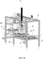
- the machine 1 for packaging pouch wrappings comprises a support frame 2 defining an inlet section 3 for at least one group of pouch wrappings and an outlet section 4 for packaging a plurality of pouch wrappings groups.
- the inlet section 3 and the outlet section 4 are realised laterally compared to a longitudinal X-direction (coinciding with a movement direction X described below).
- the inlet section 3 and the outlet section 4 can be provided specularly compared to the highlighted one, or again the inlet section 3 can be provided on a different side compared to the outlet section 4, without thereby departing from the purpose of protection of this privative.
- the inlet section 3 is configured to allow the entry of only one group of pouch wrappings to make a package comprising a single stack of pouch wrappings groups.
- the inlet section 3 may be configured to receive two or more groups of pouches wrappings horizontally arranged side-by-side with each other to realise a corresponding pack comprising two or more stacks of pouch wrappings groups.
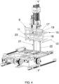
- the machine advantageously comprises first gripping means 5 mechanically mounted on said support frame 2 in the proximity of said inlet section 3 and configured and controlled to be movable at least between a loading configuration in which they receive said group of pouch wrappings, a first unloading configuration and a second unloading configuration rotated about 180° compared to said first unloading configuration.
- the machine 1 further comprises second gripping means 6 mechanically mounted on said support frame 2 and configured and controlled to be movable between a first configuration in which they pick up said group of pouch wrappings directly from said first gripping means 5 in said first unloading configuration with said group of pouch wrappings in a first angular position and, alternatively, in said second unloading configuration with said group of pouch wrappings in a second angular position, and a second configuration in which they release said group of pouch wrappings to form a stack of pouch wrappings groups.
- second gripping means 6 mechanically mounted on said support frame 2 and configured and controlled to be movable between a first configuration in which they pick up said group of pouch wrappings directly from said first gripping means 5 in said first unloading configuration with said group of pouch wrappings in a first angular position and, alternatively, in said second unloading configuration with said group of pouch wrappings in a second angular position, and a second configuration in which they release said group of pouch wrappings to form a stack of pouch wrappings groups.
- the stack of pouch wrappings groups is made with groups vertically stacked with each other in the first angular position and in the second angular position alternately.
- the packaging means 7 are mechanically mounted on said support frame 2 and configured to receive said stack of pouch wrappings groups and wrap said stack with at least one layer of flexible material and thus realize said package.
- said first gripping means 5 are configured to rotate about a first substantially vertical rotation axis Y, wherein said first unloading configuration is rotated about 90° clockwise compared to said loading configuration and said second unloading configuration is rotated about 90° counter clockwise compared to said loading configuration.
- said second gripping means 6 are configured at least to rotate about a second rotation axis Y' substantially vertical and parallel to said first rotation axis Y of said first gripping means 5, wherein in a first angular position they are turned towards said first gripping means 5 to pick up said group of pouch wrappings and in a second angular position they are turned towards said packaging means 7.
- said second gripping means 6 in said second configuration are intersected with said first gripping means 5 in said first unloading configuration or in said second unloading configuration to pick up said pouch wrappings group.
- said first gripping means comprise a first loading base 9 configured to support said pouch wrappings groups and comprising a first series of elongated elements 10 parallel to each other and spaced apart.
- said second gripping means 6 comprise a second loading base 11 configured to support said pouch wrappings group and comprising a second series of elongated elements 12 parallel to each other and spaced apart and configured to be interposed between said first series of elongated elements 10 with said second gripping means 6 in said first configuration.
- said first gripping means 5 comprise an upper jaw 13 movable between an open configuration, wherein it is moved away from said first loading base 9 to allow said pouch wrappings group to rest on said first loading base 9, and a closed configuration wherein it is placed substantially counter faced to said first loading base 9 to block said pouch wrappings group.
- the upper jaw 13 of the first gripping means 5 is rotatably mounted at an end of said first loading base 9 and is rotatably movable around a rotation axis Z orthogonal compared to said first rotation axis Y and preferably is substantially horizontal. In this way, the upper jaw 13 is rotatable around the horizontal rotation axis X between the open configuration and the closed configuration.
- the first gripping means 5 block the pouch wrappings group on the first loading base 9 by movement of the first upper jaw 13 from the open configuration to the closed configuration, such that the pouch wrappings group remains stable during movement of the first gripping means 5 from the loading configuration to the first unloading configuration or to the second unloading configuration.
- first upper jaw 13 of the first gripping means 5 is configured to be moved from the closed configuration to the open configuration when the first gripping means 5 themselves reach the first unloading configuration or the second unloading configuration. In this way, the first gripping means 5 allow the second gripping means 6 to pick up the pouch wrappings group.
- said upper jaw 13 of said first gripping means 5 comprises a third series of elongated elements 14 which are parallel to each other and spaced apart and arranged vertically offset from corresponding first series of elongated elements 10, thereby defining spaces between them to allow the insertion of said second series of elongated elements 12 with said second gripping means 6 in said first configuration.
- the second gripping means 6 comprise a second upper jaw 15 movable between an open configuration, wherein it is moved away from said second loading base 11 to allow the pick-up of said set of pouch wrappings from said first gripping means 5, and a closed configuration wherein it is placed substantially counter faced to said second loading base 11 to block said set of pouch wrappings, in particular to hold them against said second loading base 11.
- the second gripping means 6 are movable along a movement direction X, substantially orthogonal compared to the second rotation axis Y'.
- the first series of elongated elements 10 of the first loading base 9 of the first gripping means 5 and preferably the second series of elongated elements 12 of the second loading base 11 are movable parallel to the movement direction X, i.e. they are movable substantially horizontally.
- the second gripping means 6 are moved along the movement direction X towards the first gripping means to intersect the second series of elongated elements 12 of the second loading base 11 with the first series of elongated elements 10 of the first loading base 9.
- the second series of elongated elements 12, as intersected with the first series of elongated elements 10, is placed at an equal and preferably lower height than the height at which the first series of elongated elements 10 is arranged.
- the first upper jaw 13 is placed in its open configuration to allow the second gripping means 6 to pick up the pouch wrapping.
- the second gripping means 6, with the second series of elongated elements 12 placed below the first series of elongated elements 10 and thus below the pouch wrappings group resting on the first loading base 9, are moved vertically along the second rotation axis Y', so that the second series of elongated elements 12 passes between the first series of elongated elements 10, thereby picking up the pouch wrappings group.
- the second gripping means 6 pick up the pouch wrappings group in the same angular position in which they are presented by the first gripping means 5, i.e. in particular with the closed bottoms arranged either on one side or on the other side of the second loading base 11.
- the movement of the second gripping means 6 is numerically controlled by an electronic control unit and is commanded to intersect with the first gripping means 5 for a linear distance equal to or greater than the width of the pouch wrapping.
- the electronic control unit controls the movement of the second gripping means 6 along the movement direction X for a linear distance equal to a multiple of the width of the pouch wrappings. For example, if a pack is to be made with two groups stacks, then the second gripping means 6 will move at the intersection of the first gripping means 5 by a distance equal to or greater than two times the width of the gripping means. Appropriately, following the pick-up of the pouch wrappings group, the second gripping means 6 is moved from its open configuration to the second closed configuration.
- the first series of elongated elements 10 of the first loading base 9 are movable towards or away from each other to define a first loading base 9 of different width.
- the second series of elongated elements 12 of the second loading base 11 are movable towards or away from each other to define a second loading base 11 of different amplitude.
- the first gripping means 5 comprise a support ferrule 16 on which the elongated elements 10 of the first loading base 9 are mounted.
- the support ferrule 16 is interchangeable by an operator with a ferrule 16 having elongated elements 10 at different relative spacing.
- the second gripping means 6 comprise a support crossbar17 extending transversely compared to the second rotation axis Y' and compared to the movement direction X and preferably substantially horizontally, on which the elongated elements 12 are fixed.
- the elongated elements 12 of the second loading base 11 are fixed to the support crossbar17 by means of corresponding fixing pillars 18 extending parallel to the second rotation axis Y'.
- the support crossbar 17 (preferably fixed) is arranged at a higher height than the second loading base 11 defined by the second series of elongated elements 12. Therefore, the fixing pillars 18 are arranged as a mechanical connection between the support crossbar 17 and the elongated elements 12 thereof.
- the support crossbar 17 is provided with mechanical coupling means, comprising in particular a plurality of holes 19 arranged along its prevailing extension and configured to be occupied by corresponding mechanical coupling counter-means of the fixing pillars 18.
- the operator is able to vary the relative distance between the second series of elongated elements 12 of the second loading base 11 on the basis of necessity, i.e. on the basis of, for example, a different size of the pouch wrapping.
- the machine 1 comprises a stacking zone 8 configured to receive said stack of pouch wrappings groups is configured to be moved parallel to a substantially horizontal movement direction X to transport said stack towards said packaging means 7.
- the stacking zone 8 of the machine 1 advantageously comprises a platform 20 configured to support the pouch wrappings group stacked with each other, arranged by the second gripping means 6.
- the platform 20 of the stacking zone 8 may support a single stack of pouch wrappings group.
- the platform 20 of the stacking zone 8 may be configured and/or dimensioned to support two or more stacks of pouch wrappings groups.
- the stacking zone 8 advantageously comprises stop means 21, extending substantially vertically and configured to act as a stop and/or end-stack for the pouch wrappings group arranged by the second gripping means 6.
- the second gripping means are configured to be moved along the direction X until reaching the second series of elongated elements 12 the stacking zone 8, at a higher height than the stop means 21, as long as the group of pouch casings exceeds, along the movement direction X, the stop barrier means 21.
- said second gripping means 6 are movable, preferably vertically, at least along said second rotation axis Y' to release said pouch wrappings group above at least one further pouch wrappings group.
- the second gripping means 6 are moved vertically along said second rotation axis Y' until the pouch wrappings group supported by the second loading base 11 reaches the platform 20 or reaches another pouch wrappings group(arranged in another angular position, i.e. with the bottom arranged on the other side).
- the second gripping means 6 Upon reaching such a position, the second gripping means 6 are moved in the open configuration and thus along the movement direction X.
- the pouch wrappings group encounters the stop means 21 which block their movement, holding them in their position on the platform 20, thus creating a stack of pouch wrappings groups staggered between them, i.e. alternately provided with a different angular position.
- the stack of pouch wrappings group is advantageously formed against the stop means 21 and the assemblies are arranged such that the bottom of one assembly is overlaid by the openings of a subsequent assembly and vice versa.
- the stop means 21 comprise at least one pillar 22 and preferably two pillars 22 parallel to each other and configured to be interposed to the second series of elongated elements 12 of the second loading base 11 of the second gripping means 6.
- the at least one pillar 22 of the stop means 21 comprises, at an upper free end thereof, a wheel 23 configured to assist the descent of the pouch wrappings group with the second gripping means and, preferably, to assist the handling of the flexible material layer of the packaging means 7, as described in more detail below.
- the stop means 21 are movable parallel to the movement direction X to push the stack of pouch wrappings group towards the packaging means 7.
- the packaging means 7 comprise at least one support base 24 configured to support the stack of pouch wrappings group pushed by the stop means 21 from the stacking zone 8.
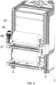
- a tract of a flexible material layer 25 is interposed between the stop means 21 and the support base 24 of the packaging means, which extends substantially vertically. More in detail, the layer of flexible material 25 is maintained in said vertical position by suitable tensioning means 26 comprising at least one reel and preferably two reels 27 of flexible material.
- the tensioning means 26 comprise two reels 27 of flexible material web, preferably rotatably constrained to the support frame 2, around corresponding preferably horizontal and parallel axes of rotation, at one end thereof, located in proximity to the support base 24.
- Each reel 27 is unrolled in the opposite direction to the other and the free edges of each strip of flexible material are mechanically constrained to each other at the section of flexible material interposed between the stop means 21 and the packaging means 7.
- the stack of pouch wrappings group pushed by the stop means 21 intercepts the vertical tract of flexible material 25, which wraps itself around the same stack, partially wrapping it until the stack reaches the support base 24 of the packaging means 7.
- the tract 25 of flexible material wraps around a front part of the stack and defines two substantially horizontal or inclined tracts, with the stack placed above the support base 24.
- the reels 27 of flexible material are unrolled to allow proper wrapping of the stack and preferably are actively unroll by at least one electric motor 28 connected to at least one reel 27. Active unrolling of the reels 27 obviates the risk that the pulling performed by the pushing of the stop means 21 and the tapping of the stack will tear and/or damage the flexible material.
- the flexible material 25 is a plastic material, e.g. transparent, such as a polyethylene or similar.
- the packaging means 7 comprise a sealing and cutting device 29 interposed between the stop means 21 and the tract 25 of flexible material, preferably comprising at least one sealing bar, which extends horizontally transversely compared to the movement direction X and is movable between a raised position in which it allows the passage of the 21 pushing the stack of pouch wrappings groups and a lowered position in which it intercepts the substantially horizontal or inclined layers of flexible material and thermally joins and seals them together, thereby creating a horizontal sealing line.
- a sealing and cutting device 29 interposed between the stop means 21 and the tract 25 of flexible material, preferably comprising at least one sealing bar, which extends horizontally transversely compared to the movement direction X and is movable between a raised position in which it allows the passage of the 21 pushing the stack of pouch wrappings groups and a lowered position in which it intercepts the substantially horizontal or inclined layers of flexible material and thermally joins and seals them together, thereby creating a horizontal sealing line.
- the sealing and cutting device 29 further comprises at least one cutting bar, arranged parallel to the sealing bar.
- the sealing and cutting device 29 comprises two sealing bars.
- the cutting bar of the sealing and cutting device 29 is interposed between the two sealing bars, such that with the sealing and cutting device 29 intercepting substantially horizontal or inclined sections of the flexible material seals along the two sealing lines made by the two sealing bars and cuts along a cutting line interposed between the two sealing lines.
- the sealing and cutting device 29 allows the plastic material to be closed around the stack of pouch wrappings groups and simultaneously joins together the free edges of the plastic material strips unroll from the two reels to define again a vertical tract 25 of flexible material intended to be intercepted again by a subsequent stack of pouch wrappings groups.
- the packaging means 7 comprise a heating means 30 provided at the support base 24 and configured to heat the flexible plastic material wrapping the stack of pouch wrappings group.
- the plastic material is a shrinkable material, i.e. configured to decrease its extension when exposed to a heat source.
- the heating means 30 are configured to shrink the plastic material wrapping the stack and thus make a compact and easy to handle and transport package.
- the heating means 30 comprise a device for delivering a flow of hot air, in particular comprising at least one duct 31 and preferably two ducts 31 arranged on the sides of the support base 24, in particular symmetrically compared to the movement direction X.
- the ducts 31 terminate with exhaust ports facing a volume defined above the support base 24 intended to be occupied by the stack wrapped by the flexible material.
- the discharge outlets of the ducts 31 of the heating means 30 are configured to emit said flow of hot air over the side edges of the shrinkable plastic material in order to make them retract and thus wrap the stack of pouch wrappings groups.
- the packaging means 7 comprise at least one covering body 32 movable between a position distal to the support base 24, to allow the arrival of the stack wrapped by the plastic material, and a position proximal to the support base in which it covers superiorly (and preferably at least partially also laterally) the volume defined superiorly to the support base 24 and thus the stack of pouch wrappings groups.
- the covering body 32 is provided with side openings 33 configured to be aligned with the duct discharge outlets 31 when in the position proximal to the support base 24 to allow the flow of hot air to enter it.
- the covering body 32 is configured to retain within it the hot air and thus the heat generated by the heating means 30.
- the machine 1 comprises at least one electronic control unit (not illustrated in the appended figures), at which it is configured and/or programmed to control the movement of appropriate handling means mechanically mounted on the support frame.
- the movement means are configured to move each moving part of the machine 1, for example the movement of the first and second gripping means 5, 6 and/or the handling of the stop barrier means 21 and/or the movement of the sealing and cutting device 29 etc.
- the machine 1 comprises at least one user interface device, for example a screen and at least one numeric keypad and/or a touch screen, for setting initial working parameters, such as for example the size of the pouch wrappings, the number of group stacks desired in the final package, etc.
- the movement of the moving parts of machine 1 is carried out in feedback and/or numerical control on the basis of appropriate command signals sent by the electronic control unit.
- the pouch wrappings machine is particularly advantageous in that:
Landscapes
- Engineering & Computer Science (AREA)
- Mechanical Engineering (AREA)
- Auxiliary Devices For And Details Of Packaging Control (AREA)
- Supplying Of Containers To The Packaging Station (AREA)
Claims (15)
- Machine pour l'emballage de sachets, comprenant:- un cadre de support (2) définissant une section d'entrée (3) pour au moins un groupe d'emballage de sachets et une section de sortie (4) pour un emballage d'une pluralité de groupes d'emballage de sachets;- des premiers moyens de préhension (5) montés mécaniquement sur ledit cadre de support (2) à proximité de ladite section d'entrée (3) et configurés et commandés pour être mobiles au moins entre une configuration de chargement dans laquelle ils reçoivent ledit groupe d'emballage de sachets, une première configuration de déchargement et une deuxième configuration de déchargement tournée d'environ 180° par rapport à ladite première configuration de déchargement;- des moyens d'emballage (7) montés mécaniquement sur ledit cadre de support (2) et configurés pour recevoir ladite pile de groupes d'emballage de sachets et envelopper ladite pile avec au moins une couche de matériau flexible et ainsi réaliser ledit emballage;- des deuxièmes moyens de préhension (6) montés mécaniquement sur ledit cadre de support (2); ladite machine étant caractérisée en ce que lesdits deuxièmes moyens de préhension (6) sont configurés et commandés pour être mobiles entre une première configuration, dans laquelle ils saisissent ledit groupe d'emballage de sachets directement depuis ledit premier moyen de préhension (5) dans ladite première configuration de déchargement avec ledit groupe d'emballage de sachets dans une première position angulaire, et en variante, dans ladite deuxième configuration de déchargement avec ledit groupe d'emballage de sachets dans une deuxième position angulaire, et une deuxième configuration dans laquelle ils libèrent ledit groupe d'emballage de sachets pour former une pile de groupes d'emballage de sachets;ladite pile de groupes d'emballage de sachets étant constituée de groupes d'emballage de sachets empilés verticalement ensemble dans la première position angulaire et dans la deuxième position angulaire de manière alternée.
- Machine d'emballage de sachets selon la revendication 1, caractérisée en ce que lesdits premiers moyens de préhension (5) sont configurés pour tourner autour d'un premier axe de rotation (Y) sensiblement vertical, dans laquelle ladite première configuration de déchargement est tournée d'environ 90° dans le sens des aiguilles d'une montre par rapport à ladite configuration de chargement et à ladite deuxième configuration de déchargement tournée d'environ 90° dans le sens inverse des aiguilles d'une montre par rapport à ladite configuration de chargement.
- Machine d'emballage de sachets selon la revendication 2, caractérisée en ce que lesdits deuxièmes moyens de préhension (6) sont configurés au moins pour tourner autour d'un deuxième axe de rotation (Y') sensiblement vertical et parallèle audit premier axe de rotation (Y) desdits premiers moyens de préhension (5), dans lesquels, dans une première position angulaire, ils sont tournés vers lesdits premiers moyens de préhension (5) pour saisir ledit groupe d'emballage de sachets et dans une deuxième position angulaire, ils sont tournés vers lesdits moyens d'emballage (7).
- Machine d'emballage de sachets selon une ou plusieurs des revendications précédentes, caractérisée en ce que lesdits deuxièmes moyens de préhension (6) dans ladite deuxième configuration sont en intersection avec lesdits premiers moyens de préhension (5) dans ladite première configuration de déchargement ou dans ladite deuxième configuration de déchargement, pour récupérer ledit groupe d'emballage de sachets.
- Machine d'emballage de sachets selon la revendication 4, caractérisée en ce que lesdits premiers moyens de préhension comprennent une première base de chargement (9) configurée pour supporter ledit groupe d'emballage de sachets et comprenant une première série d'éléments allongés (10) parallèles les uns aux autres et espacés.
- Machine d'emballage de sachets selon la revendication 5, caractérisée en ce que lesdits deuxièmes moyens de préhension comprennent une deuxième base de chargement (11) configurée pour supporter ledit groupe d'emballage de sachets et comprenant une deuxième série d'éléments allongés (12) parallèles les uns aux autres et espacés. et configuré pour être interposé entre ladite première série d'éléments allongés (10) avec lesdits deuxièmes moyens de préhension (6) dans ladite première configuration.
- Machine d'emballage de sachets selon la revendication 5 ou 6, caractérisée en ce que lesdits premiers moyens de préhension comprennent une mâchoire supérieure (13) mobile entre une configuration ouverte, dans laquelle elle est déplacée de ladite première base de chargement (9) pour permettre le support dudit groupe d'emballage de sachets sur ladite première base de chargement (9), et une configuration fermée dans laquelle il est placé sensiblement contrefait sur ladite première base de chargement (9) pour bloquer ledit groupe d'emballage de sachets.
- Machine d'emballage de sachets selon la revendication 7, caractérisée en ce que ladite mâchoire supérieure (13) dudit premier moyen de préhension (5) comprend une troisième série d'éléments allongés (14) parallèles les uns aux autres et espacés et disposés verticalement contrefaits à la correspondants première série d'éléments allongés (10), définissant ainsi des espaces entre eux pour permettre l'insertion de ladite deuxième série d'éléments allongés (12) avec lesdits deuxièmes moyens de préhension (6) dans ladite première configuration.
- Machine d'emballage de sachets selon une ou plusieurs des revendications précédentes, caractérisée en ce que lesdits deuxièmes moyens de préhension (6) sont mobiles au moins le long dudit deuxième axe de rotation (Y') pour libérer ledit groupe d'emballage de sachets au-dessus d'au moins un autre groupe d'emballage de sachets.
- Machine d'emballages de sachets selon une ou plusieurs des revendications précédentes, caractérisée en ce qu'elle comprend une zone d'empilage (8) configurée pour recevoir ladite pile des groupes d'emballage de sachets et configurée pour être déplacée parallèlement à une direction de déplacement sensiblement horizontale (X), pour transporter ladite pile vers lesdits moyens d'emballage (7).
- Machine d'emballage de sachets selon une ou plusieurs des revendications précédentes, caractérisée en ce que lesdits premiers moyens de préhension (5) bloquent ledit groupe d'emballage de sachets sur ladite première base de chargement (9) par le mouvement de ladite première mâchoire (13) depuis la configuration ouverte à la configuration fermée, de telle sorte que ledit groupe d'emballage de sachets reste stable pendant le mouvement desdits premiers moyens de préhension (5) de la configuration de chargement à la première configuration de déchargement ou à la deuxième configuration de déchargement.
- Machine d'emballage de sachets selon une ou plusieurs des revendications précédentes, caractérisée en ce que ladite première mâchoire (13) desdits premiers moyens de préhension (5) est configurée pour être déplacée de la configuration fermée à la configuration ouverte, lorsque lesdits premiers moyens de préhension (5) atteignent la première configuration de déchargement ou la deuxième configuration de déchargement.
- Machine d'emballage de sachets selon une ou plusieurs des revendications précédentes, caractérisée en ce que lesdits deuxièmes moyens de préhension (6) comprennent une deuxième mâchoire supérieure (15) mobile entre une configuration ouverte, dans laquelle elle est déplacée de ladite deuxième base de chargement (11) pour permettre la récupération dudit groupe d'emballage de sachets depuis ledit premier moyen de préhension (5), et une configuration fermée dans laquelle il est placé sensiblement contrefait sur ladite deuxième base de chargement (11) pour bloquer ledit groupe d'emballage de sachets.
- Machine d'emballage de sachets selon une ou plusieurs des revendications précédentes, caractérisée en ce que le mouvement du deuxième moyen de préhension (6) est commandé numériquement par une unité de commande électronique et est commandé pour croiser le premier moyen de préhension (5) pour une distance linéaire égale ou supérieure à la largeur de l'emballage des sachets.
- Machine d'emballage de sachets selon une ou plusieurs des revendications précédentes, caractérisée en ce que la première série d'éléments allongés (10) de la première base de chargement (9) sont mobiles les uns vers les autres ou les éloignent pour définir une première base de chargement (9) de différentes largeurs.
Applications Claiming Priority (1)
| Application Number | Priority Date | Filing Date | Title |
|---|---|---|---|
| IT102021000032072A IT202100032072A1 (it) | 2021-12-21 | 2021-12-21 | Macchina per confezionare involucri a sacchetto |
Publications (3)
| Publication Number | Publication Date |
|---|---|
| EP4201822A1 EP4201822A1 (fr) | 2023-06-28 |
| EP4201822B1 true EP4201822B1 (fr) | 2024-09-18 |
| EP4201822C0 EP4201822C0 (fr) | 2024-09-18 |
Family
ID=80625185
Family Applications (1)
| Application Number | Title | Priority Date | Filing Date |
|---|---|---|---|
| EP22214752.2A Active EP4201822B1 (fr) | 2021-12-21 | 2022-12-19 | Dispositif pour emballer des groupes d'emballages de sachet |
Country Status (2)
| Country | Link |
|---|---|
| EP (1) | EP4201822B1 (fr) |
| IT (1) | IT202100032072A1 (fr) |
Family Cites Families (5)
| Publication number | Priority date | Publication date | Assignee | Title |
|---|---|---|---|---|
| EP0146643A1 (fr) * | 1983-12-06 | 1985-07-03 | Icoma Packtechnik GmbH | Dispositif de palettisation |
| EP1657191A1 (fr) * | 2004-11-12 | 2006-05-17 | Bema s.r.l. | Procédé de palettisation de conteneurs déformables et instables |
| EP2358617B2 (fr) * | 2008-11-21 | 2017-12-13 | Dematic Corp. | Appareil d'empilement et procédé d'empilement multicouche d'objets sur un support |
| US8997438B1 (en) * | 2012-09-18 | 2015-04-07 | David M. Fallas | Case packing system having robotic pick and place mechanism and dual dump bins |
| WO2019035325A1 (fr) * | 2017-08-16 | 2019-02-21 | 株式会社イシダ | Dispositif d'emballage de boîtes |
-
2021
- 2021-12-21 IT IT102021000032072A patent/IT202100032072A1/it unknown
-
2022
- 2022-12-19 EP EP22214752.2A patent/EP4201822B1/fr active Active
Also Published As
| Publication number | Publication date |
|---|---|
| IT202100032072A1 (it) | 2023-06-21 |
| EP4201822A1 (fr) | 2023-06-28 |
| EP4201822C0 (fr) | 2024-09-18 |
Similar Documents
| Publication | Publication Date | Title |
|---|---|---|
| EP1988020B1 (fr) | Equipement et procédé pour fabriquer en continu des paquets de piles de carreaux ou similaires | |
| CN105492327B (zh) | 用可伸缩膜包裹物品的冷加工收缩包裹机及相关方法 | |
| CN102358445B (zh) | 在物品堆周围包裹薄膜的设备和方法 | |
| ES2304648T3 (es) | Maquina para empaquetar en cajas semiautomatica. | |
| JP6082000B2 (ja) | 1つの容器が他の容器の内側にある少なくとも2つの容器を各々が備えた硬質パケットを製造するための包装機及び方法 | |
| JP2019520238A (ja) | 段ボールブランクの折曲げステーション、及び段ボールブランクから得られる段ボール箱の中に物品を梱包するための機械 | |
| JPS5952092B2 (ja) | 周囲にシ−トが被着されている一個物貨物特に袋物のパレツトのない積み重ねを作るための装置 | |
| EP0860356B1 (fr) | Appareil pour placer de groupes d'objets sur des palettes | |
| EP4201822B1 (fr) | Dispositif pour emballer des groupes d'emballages de sachet | |
| JP7492579B2 (ja) | 煎じ出し製品を含むフィルタバッグを製造するための包装機械 | |
| US6935091B2 (en) | Method and apparatus for wrapping articles with a packaging sheet | |
| CN101181938B (zh) | 片材供给装置及使用该装置的片材包装机 | |
| EP1775233A1 (fr) | Emballage externe pour groupes de rouleaux d'objets emballés | |
| US20250074639A1 (en) | An apparatus for packaging articles | |
| EP2392513B1 (fr) | Équipement, procédé et station pour l'emballage latéral de produits au moyen d'un film plastique | |
| KR100485788B1 (ko) | 사면 포장기 | |
| EP1254839B1 (fr) | Méthode et dispositif pour envelopper des articles avec une feuille d'emballage | |
| EP0532785B1 (fr) | Machine d'enveloppement avec un film et d'encaissage spécialement pour bobines de fil et similaires | |
| JP7614645B2 (ja) | 位置ずれ防止装置および包装機 | |
| CN112839872A (zh) | 用于聚拢和卸载物品的设备和方法 | |
| EP3221219B1 (fr) | Ligne pour emballer des produits dans un conteneur | |
| ITMI950774A1 (it) | Dispositivo per piegare lembi di piegatura di una confezione e per trasportare la stessa | |
| EP2077233B1 (fr) | Procédé et agencement pour la mise en place de rouleaux de matériau d'emballage et pour entraîner le matériau d'emballage dans une machine de conditionnement de rouleaux | |
| CN120897875A (zh) | 用于形成产品的层的机器和方法 | |
| EP4671141A2 (fr) | Machine d'emballage pour emballer des enveloppes de sacs |
Legal Events
| Date | Code | Title | Description |
|---|---|---|---|
| PUAI | Public reference made under article 153(3) epc to a published international application that has entered the european phase |
Free format text: ORIGINAL CODE: 0009012 |
|
| STAA | Information on the status of an ep patent application or granted ep patent |
Free format text: STATUS: THE APPLICATION HAS BEEN PUBLISHED |
|
| AK | Designated contracting states |
Kind code of ref document: A1 Designated state(s): AL AT BE BG CH CY CZ DE DK EE ES FI FR GB GR HR HU IE IS IT LI LT LU LV MC ME MK MT NL NO PL PT RO RS SE SI SK SM TR |
|
| STAA | Information on the status of an ep patent application or granted ep patent |
Free format text: STATUS: REQUEST FOR EXAMINATION WAS MADE |
|
| 17P | Request for examination filed |
Effective date: 20231115 |
|
| RBV | Designated contracting states (corrected) |
Designated state(s): AL AT BE BG CH CY CZ DE DK EE ES FI FR GB GR HR HU IE IS IT LI LT LU LV MC ME MK MT NL NO PL PT RO RS SE SI SK SM TR |
|
| GRAP | Despatch of communication of intention to grant a patent |
Free format text: ORIGINAL CODE: EPIDOSNIGR1 |
|
| STAA | Information on the status of an ep patent application or granted ep patent |
Free format text: STATUS: GRANT OF PATENT IS INTENDED |
|
| RIC1 | Information provided on ipc code assigned before grant |
Ipc: B65B 35/50 20060101ALI20240404BHEP Ipc: B65B 5/06 20060101ALI20240404BHEP Ipc: B65B 35/52 20060101ALI20240404BHEP Ipc: B65B 35/56 20060101ALI20240404BHEP Ipc: B65B 35/36 20060101ALI20240404BHEP Ipc: B65B 35/16 20060101ALI20240404BHEP Ipc: B65B 11/00 20060101AFI20240404BHEP |
|
| INTG | Intention to grant announced |
Effective date: 20240418 |
|
| GRAS | Grant fee paid |
Free format text: ORIGINAL CODE: EPIDOSNIGR3 |
|
| GRAA | (expected) grant |
Free format text: ORIGINAL CODE: 0009210 |
|
| STAA | Information on the status of an ep patent application or granted ep patent |
Free format text: STATUS: THE PATENT HAS BEEN GRANTED |
|
| AK | Designated contracting states |
Kind code of ref document: B1 Designated state(s): AL AT BE BG CH CY CZ DE DK EE ES FI FR GB GR HR HU IE IS IT LI LT LU LV MC ME MK MT NL NO PL PT RO RS SE SI SK SM TR |
|
| REG | Reference to a national code |
Ref country code: GB Ref legal event code: FG4D |
|
| REG | Reference to a national code |
Ref country code: CH Ref legal event code: EP |
|
| REG | Reference to a national code |
Ref country code: IE Ref legal event code: FG4D |
|
| REG | Reference to a national code |
Ref country code: DE Ref legal event code: R096 Ref document number: 602022006215 Country of ref document: DE |
|
| U01 | Request for unitary effect filed |
Effective date: 20241015 |
|
| U07 | Unitary effect registered |
Designated state(s): AT BE BG DE DK EE FI FR IT LT LU LV MT NL PT RO SE SI Effective date: 20241031 |
|
| PG25 | Lapsed in a contracting state [announced via postgrant information from national office to epo] |
Ref country code: NO Free format text: LAPSE BECAUSE OF FAILURE TO SUBMIT A TRANSLATION OF THE DESCRIPTION OR TO PAY THE FEE WITHIN THE PRESCRIBED TIME-LIMIT Effective date: 20241218 |
|
| PG25 | Lapsed in a contracting state [announced via postgrant information from national office to epo] |
Ref country code: GR Free format text: LAPSE BECAUSE OF FAILURE TO SUBMIT A TRANSLATION OF THE DESCRIPTION OR TO PAY THE FEE WITHIN THE PRESCRIBED TIME-LIMIT Effective date: 20241219 |
|
| PG25 | Lapsed in a contracting state [announced via postgrant information from national office to epo] |
Ref country code: HR Free format text: LAPSE BECAUSE OF FAILURE TO SUBMIT A TRANSLATION OF THE DESCRIPTION OR TO PAY THE FEE WITHIN THE PRESCRIBED TIME-LIMIT Effective date: 20240918 |
|
| PG25 | Lapsed in a contracting state [announced via postgrant information from national office to epo] |
Ref country code: RS Free format text: LAPSE BECAUSE OF FAILURE TO SUBMIT A TRANSLATION OF THE DESCRIPTION OR TO PAY THE FEE WITHIN THE PRESCRIBED TIME-LIMIT Effective date: 20241218 |
|
| PG25 | Lapsed in a contracting state [announced via postgrant information from national office to epo] |
Ref country code: RS Free format text: LAPSE BECAUSE OF FAILURE TO SUBMIT A TRANSLATION OF THE DESCRIPTION OR TO PAY THE FEE WITHIN THE PRESCRIBED TIME-LIMIT Effective date: 20241218 Ref country code: NO Free format text: LAPSE BECAUSE OF FAILURE TO SUBMIT A TRANSLATION OF THE DESCRIPTION OR TO PAY THE FEE WITHIN THE PRESCRIBED TIME-LIMIT Effective date: 20241218 Ref country code: HR Free format text: LAPSE BECAUSE OF FAILURE TO SUBMIT A TRANSLATION OF THE DESCRIPTION OR TO PAY THE FEE WITHIN THE PRESCRIBED TIME-LIMIT Effective date: 20240918 Ref country code: GR Free format text: LAPSE BECAUSE OF FAILURE TO SUBMIT A TRANSLATION OF THE DESCRIPTION OR TO PAY THE FEE WITHIN THE PRESCRIBED TIME-LIMIT Effective date: 20241219 |
|
| U21 | Renewal fee for the european patent with unitary effect paid with additional fee |
Year of fee payment: 3 Effective date: 20250228 |
|
| PG25 | Lapsed in a contracting state [announced via postgrant information from national office to epo] |
Ref country code: IS Free format text: LAPSE BECAUSE OF FAILURE TO SUBMIT A TRANSLATION OF THE DESCRIPTION OR TO PAY THE FEE WITHIN THE PRESCRIBED TIME-LIMIT Effective date: 20250118 |
|
| PG25 | Lapsed in a contracting state [announced via postgrant information from national office to epo] |
Ref country code: SM Free format text: LAPSE BECAUSE OF FAILURE TO SUBMIT A TRANSLATION OF THE DESCRIPTION OR TO PAY THE FEE WITHIN THE PRESCRIBED TIME-LIMIT Effective date: 20240918 |
|
| PG25 | Lapsed in a contracting state [announced via postgrant information from national office to epo] |
Ref country code: ES Free format text: LAPSE BECAUSE OF FAILURE TO SUBMIT A TRANSLATION OF THE DESCRIPTION OR TO PAY THE FEE WITHIN THE PRESCRIBED TIME-LIMIT Effective date: 20240918 |
|
| PG25 | Lapsed in a contracting state [announced via postgrant information from national office to epo] |
Ref country code: CZ Free format text: LAPSE BECAUSE OF FAILURE TO SUBMIT A TRANSLATION OF THE DESCRIPTION OR TO PAY THE FEE WITHIN THE PRESCRIBED TIME-LIMIT Effective date: 20240918 Ref country code: PL Free format text: LAPSE BECAUSE OF FAILURE TO SUBMIT A TRANSLATION OF THE DESCRIPTION OR TO PAY THE FEE WITHIN THE PRESCRIBED TIME-LIMIT Effective date: 20240918 |
|
| PG25 | Lapsed in a contracting state [announced via postgrant information from national office to epo] |
Ref country code: SK Free format text: LAPSE BECAUSE OF FAILURE TO SUBMIT A TRANSLATION OF THE DESCRIPTION OR TO PAY THE FEE WITHIN THE PRESCRIBED TIME-LIMIT Effective date: 20240918 |
|
| PG25 | Lapsed in a contracting state [announced via postgrant information from national office to epo] |
Ref country code: MC Free format text: LAPSE BECAUSE OF FAILURE TO SUBMIT A TRANSLATION OF THE DESCRIPTION OR TO PAY THE FEE WITHIN THE PRESCRIBED TIME-LIMIT Effective date: 20240918 |
|
| PLBE | No opposition filed within time limit |
Free format text: ORIGINAL CODE: 0009261 |
|
| STAA | Information on the status of an ep patent application or granted ep patent |
Free format text: STATUS: NO OPPOSITION FILED WITHIN TIME LIMIT |
|
| 26N | No opposition filed |
Effective date: 20250619 |
|
| PG25 | Lapsed in a contracting state [announced via postgrant information from national office to epo] |
Ref country code: IE Free format text: LAPSE BECAUSE OF NON-PAYMENT OF DUE FEES Effective date: 20241219 |
|
| U21 | Renewal fee for the european patent with unitary effect paid with additional fee |
Year of fee payment: 4 Effective date: 20260126 |