EP4201825A1 - Machine de stratification de film et son procédé d'utilisation - Google Patents
Machine de stratification de film et son procédé d'utilisation Download PDFInfo
- Publication number
- EP4201825A1 EP4201825A1 EP21798262.8A EP21798262A EP4201825A1 EP 4201825 A1 EP4201825 A1 EP 4201825A1 EP 21798262 A EP21798262 A EP 21798262A EP 4201825 A1 EP4201825 A1 EP 4201825A1
- Authority
- EP
- European Patent Office
- Prior art keywords
- film
- motor
- assembly
- cold
- roller
- Prior art date
- Legal status (The legal status is an assumption and is not a legal conclusion. Google has not performed a legal analysis and makes no representation as to the accuracy of the status listed.)
- Pending
Links
- 238000010030 laminating Methods 0.000 title claims abstract description 63
- 238000000034 method Methods 0.000 title claims abstract description 19
- 230000000712 assembly Effects 0.000 claims abstract description 47
- 238000000429 assembly Methods 0.000 claims abstract description 47
- 230000005540 biological transmission Effects 0.000 claims abstract description 44
- 238000007789 sealing Methods 0.000 claims description 40
- 210000000078 claw Anatomy 0.000 claims description 15
- 230000005611 electricity Effects 0.000 claims description 14
- 230000003068 static effect Effects 0.000 claims description 14
- 230000008030 elimination Effects 0.000 claims description 11
- 238000003379 elimination reaction Methods 0.000 claims description 11
- 239000003638 chemical reducing agent Substances 0.000 description 12
- 238000010586 diagram Methods 0.000 description 10
- 238000003475 lamination Methods 0.000 description 5
- 238000004806 packaging method and process Methods 0.000 description 5
- 238000004519 manufacturing process Methods 0.000 description 4
- 239000001120 potassium sulphate Substances 0.000 description 4
- 238000005520 cutting process Methods 0.000 description 3
- 230000008878 coupling Effects 0.000 description 2
- 238000010168 coupling process Methods 0.000 description 2
- 238000005859 coupling reaction Methods 0.000 description 2
- 238000001514 detection method Methods 0.000 description 2
- 230000000694 effects Effects 0.000 description 2
- 238000012986 modification Methods 0.000 description 2
- 230000004048 modification Effects 0.000 description 2
- 238000004804 winding Methods 0.000 description 2
- 230000001133 acceleration Effects 0.000 description 1
- 238000006073 displacement reaction Methods 0.000 description 1
- 239000007888 film coating Substances 0.000 description 1
- 238000009501 film coating Methods 0.000 description 1
- 238000010438 heat treatment Methods 0.000 description 1
- 230000001771 impaired effect Effects 0.000 description 1
- 238000012858 packaging process Methods 0.000 description 1
Images


Classifications
-
- B—PERFORMING OPERATIONS; TRANSPORTING
- B65—CONVEYING; PACKING; STORING; HANDLING THIN OR FILAMENTARY MATERIAL
- B65B—MACHINES, APPARATUS OR DEVICES FOR, OR METHODS OF, PACKAGING ARTICLES OR MATERIALS; UNPACKING
- B65B9/00—Enclosing successive articles, or quantities of material, e.g. liquids or semiliquids, in flat, folded, or tubular webs of flexible sheet material; Subdividing filled flexible tubes to form packages
- B65B9/10—Enclosing successive articles, or quantities of material, in preformed tubular webs, or in webs formed into tubes around filling nozzles, e.g. extruded tubular webs
- B65B9/13—Enclosing successive articles, or quantities of material, in preformed tubular webs, or in webs formed into tubes around filling nozzles, e.g. extruded tubular webs the preformed tubular webs being supplied in a flattened state
- B65B9/135—Enclosing successive articles, or quantities of material, in preformed tubular webs, or in webs formed into tubes around filling nozzles, e.g. extruded tubular webs the preformed tubular webs being supplied in a flattened state for palletised loads
-
- B—PERFORMING OPERATIONS; TRANSPORTING
- B65—CONVEYING; PACKING; STORING; HANDLING THIN OR FILAMENTARY MATERIAL
- B65B—MACHINES, APPARATUS OR DEVICES FOR, OR METHODS OF, PACKAGING ARTICLES OR MATERIALS; UNPACKING
- B65B11/00—Wrapping, e.g. partially or wholly enclosing, articles or quantities of material, in strips, sheets or blanks, of flexible material
- B65B11/02—Wrapping articles or quantities of material, without changing their position during the wrapping operation, e.g. in moulds with hinged folders
-
- B—PERFORMING OPERATIONS; TRANSPORTING
- B65—CONVEYING; PACKING; STORING; HANDLING THIN OR FILAMENTARY MATERIAL
- B65B—MACHINES, APPARATUS OR DEVICES FOR, OR METHODS OF, PACKAGING ARTICLES OR MATERIALS; UNPACKING
- B65B35/00—Supplying, feeding, arranging or orientating articles to be packaged
- B65B35/10—Feeding, e.g. conveying, single articles
- B65B35/22—Feeding, e.g. conveying, single articles by roller-ways
-
- B—PERFORMING OPERATIONS; TRANSPORTING
- B65—CONVEYING; PACKING; STORING; HANDLING THIN OR FILAMENTARY MATERIAL
- B65B—MACHINES, APPARATUS OR DEVICES FOR, OR METHODS OF, PACKAGING ARTICLES OR MATERIALS; UNPACKING
- B65B35/00—Supplying, feeding, arranging or orientating articles to be packaged
- B65B35/56—Orientating, i.e. changing the attitude of, articles, e.g. of non-uniform cross-section
-
- B—PERFORMING OPERATIONS; TRANSPORTING
- B65—CONVEYING; PACKING; STORING; HANDLING THIN OR FILAMENTARY MATERIAL
- B65B—MACHINES, APPARATUS OR DEVICES FOR, OR METHODS OF, PACKAGING ARTICLES OR MATERIALS; UNPACKING
- B65B41/00—Supplying or feeding container-forming sheets or wrapping material
- B65B41/12—Feeding webs from rolls
- B65B41/14—Feeding webs from rolls by grippers
-
- B—PERFORMING OPERATIONS; TRANSPORTING
- B65—CONVEYING; PACKING; STORING; HANDLING THIN OR FILAMENTARY MATERIAL
- B65B—MACHINES, APPARATUS OR DEVICES FOR, OR METHODS OF, PACKAGING ARTICLES OR MATERIALS; UNPACKING
- B65B51/00—Devices for, or methods of, sealing or securing package folds or closures; Devices for gathering or twisting wrappers, or necks of bags
- B65B51/10—Applying or generating heat or pressure or combinations thereof
- B65B51/26—Devices specially adapted for producing transverse or longitudinal seams in webs or tubes
- B65B51/30—Devices, e.g. jaws, for applying pressure and heat, e.g. for subdividing filled tubes
- B65B51/303—Devices, e.g. jaws, for applying pressure and heat, e.g. for subdividing filled tubes reciprocating along only one axis
-
- B—PERFORMING OPERATIONS; TRANSPORTING
- B65—CONVEYING; PACKING; STORING; HANDLING THIN OR FILAMENTARY MATERIAL
- B65B—MACHINES, APPARATUS OR DEVICES FOR, OR METHODS OF, PACKAGING ARTICLES OR MATERIALS; UNPACKING
- B65B57/00—Automatic control, checking, warning, or safety devices
- B65B57/10—Automatic control, checking, warning, or safety devices responsive to absence, presence, abnormal feed, or misplacement of articles or materials to be packaged
- B65B57/12—Automatic control, checking, warning, or safety devices responsive to absence, presence, abnormal feed, or misplacement of articles or materials to be packaged and operating to control, or stop, the feed of wrapping materials, containers, or packages
-
- B—PERFORMING OPERATIONS; TRANSPORTING
- B65—CONVEYING; PACKING; STORING; HANDLING THIN OR FILAMENTARY MATERIAL
- B65B—MACHINES, APPARATUS OR DEVICES FOR, OR METHODS OF, PACKAGING ARTICLES OR MATERIALS; UNPACKING
- B65B61/00—Auxiliary devices, not otherwise provided for, for operating on sheets, blanks, webs, binding material, containers or packages
- B65B61/04—Auxiliary devices, not otherwise provided for, for operating on sheets, blanks, webs, binding material, containers or packages for severing webs, or for separating joined packages
- B65B61/06—Auxiliary devices, not otherwise provided for, for operating on sheets, blanks, webs, binding material, containers or packages for severing webs, or for separating joined packages by cutting
-
- B—PERFORMING OPERATIONS; TRANSPORTING
- B65—CONVEYING; PACKING; STORING; HANDLING THIN OR FILAMENTARY MATERIAL
- B65B—MACHINES, APPARATUS OR DEVICES FOR, OR METHODS OF, PACKAGING ARTICLES OR MATERIALS; UNPACKING
- B65B11/00—Wrapping, e.g. partially or wholly enclosing, articles or quantities of material, in strips, sheets or blanks, of flexible material
- B65B2011/002—Prestretching mechanism in wrapping machines
-
- B—PERFORMING OPERATIONS; TRANSPORTING
- B65—CONVEYING; PACKING; STORING; HANDLING THIN OR FILAMENTARY MATERIAL
- B65B—MACHINES, APPARATUS OR DEVICES FOR, OR METHODS OF, PACKAGING ARTICLES OR MATERIALS; UNPACKING
- B65B2210/00—Specific aspects of the packaging machine
- B65B2210/04—Customised on demand packaging by determining a specific characteristic, e.g. shape or height, of articles or material to be packaged and selecting, creating or adapting a packaging accordingly, e.g. making a carton starting from web material
-
- Y—GENERAL TAGGING OF NEW TECHNOLOGICAL DEVELOPMENTS; GENERAL TAGGING OF CROSS-SECTIONAL TECHNOLOGIES SPANNING OVER SEVERAL SECTIONS OF THE IPC; TECHNICAL SUBJECTS COVERED BY FORMER USPC CROSS-REFERENCE ART COLLECTIONS [XRACs] AND DIGESTS
- Y02—TECHNOLOGIES OR APPLICATIONS FOR MITIGATION OR ADAPTATION AGAINST CLIMATE CHANGE
- Y02P—CLIMATE CHANGE MITIGATION TECHNOLOGIES IN THE PRODUCTION OR PROCESSING OF GOODS
- Y02P70/00—Climate change mitigation technologies in the production process for final industrial or consumer products
- Y02P70/10—Greenhouse gas [GHG] capture, material saving, heat recovery or other energy efficient measures, e.g. motor control, characterised by manufacturing processes, e.g. for rolling metal or metal working
Definitions
- the present disclosure relates to the technical field of electronic control, and in particular to a film laminating machine and a method for using the same.
- an automatic film laminating machine can realize a function of fast film coating when goods are packaged on a production line, and the efficiency of the film laminating machine far outweighs the efficiency of manual packaging. Consequently, the film laminating machine has been used more and more widely in the packaging field.
- film laminating machines currently available on the market basically can only meet one size of palletized article, only one size of palletized article can be packaged on the same production line. As a result, the compatibility of automatic equipment is seriously reduced, and it is likely to have a problem of sealing failure or instability caused by a complex structure during stretching and sealing.
- embodiments of the present disclosure provide a film laminating machine and a method for using the same, which at least partially solve the problem existing in the prior art.
- the embodiments of the present disclosure provide a film laminating machine, including:
- the bearing assembly further includes two push rods and a variable frequency motor; the two push rods are oppositely arranged on both sides of the roller table; and a drive shaft of the variable frequency motor is in transmission connection with the two push rods, and the variable frequency motor is configured to drive the two push rods to move relatively close to or away from each other, such that the two push rods push the palletized article transported onto the roller table to a middle position thereof.
- the film transporting device further includes a funnel and a suction assembly; the funnel is arranged between the roller sets and the film continuation assemblies, and an opening of the funnel faces the roller sets; and the suction assembly is arranged at a film outlet of the funnel.
- the suction assembly includes a third motor, a first suction cup set and a second suction cup set; the third motor is electrically connected to the controller; the first suction cup set and the second suction cup set are oppositely arranged and are in transmission connection with the third motor; and the third motor is configured to drive the first suction cup set and the second suction cup set to move close to or away from the cold-shrinkable film therebetween, so that the first suction cup set and the second suction cup set suck two opposite film layers of the cold-shrinkable film respectively such that the two opposite film layers are separated.
- the film transporting device further includes a static electricity elimination assembly, arranged between the film outlet of the funnel and the suction assembly.
- the film transporting device further includes a heat-sealing assembly, the heat-sealing assembly including a serrated knife, a knife groove, a first heat-sealing rod, a second heat-sealing rod and an air cylinder; the serrated knife and the air cylinder are both fixedly arranged between the static electricity elimination assembly and the suction assembly; the first heat-sealing rod and the second heat-sealing rod are oppositely arranged below the serrated knife; the serrated knife is in transmission connection with a drive shaft of the air cylinder; and, after the first heat-sealing rod and the second heat-sealing rod cooperatively perform heat seal on the cold-shrinkable film, the air cylinder is applied to drive the serrated knife to move close to or away from the knife groove, such that the serrated knife cooperates with the knife groove to cut the cold-shrinkable film.
- the heat-sealing assembly including a serrated knife, a knife groove, a first heat-sealing
- the film stretching device further includes a plurality of sliders and a second frame body; each of the sliders is connected to one film continuation assembly; a roller is arranged on a surface of each slider that is in contact with the second frame body, and is clamped onto the second frame body, such that the sliders horizontally move along a sliding chute on the second frame body by means of the roller.
- the roller is a V-shaped wheel; a bearing pulley is arranged on each of two sides of the V-shaped wheel, and is arranged on a surface of each slider that is in contact with the second frame body; and the sliders move along the second frame body by means of the bearing pulleys.
- the film continuation assembly includes pulling claws and a fourth motor; the pulling claws are fixedly arranged on the slider; a drive shaft of the fourth motor is in transmission connection with the slider; and the fourth motor is configured to drive the slider to move along a third frame body after that the pulling claws clamp the cold-shrinkable film.
- the embodiments of the present disclosure provide a method for using a film laminating machine.
- the method is applied to the film laminating machine according to any one of above embodiments, and includes:
- the film laminating machine includes: the lifting device including a first frame body, and the first motor arranged on the first frame body; the bearing assembly including a roller table arranged at a middle position below the first frame body, a palletized article being arranged on the roller table; the film transporting device including at least two roller sets and a second motor, all the roller sets are arranged at the different heights, being respectively in transmission connection with a drive shaft of the second motor, and being mounted with the cold-shrinkable films of different specifications; the film stretching device including a plurality of film continuation assemblies respectively arranged below the roller sets, each film continuation assembly being configured to clamp and stretch the cold-shrinkable film in a preset direction, and the stretching directions of the different film continuation assemblies being different; the detector arranged on the first frame body and configured to detect a specification of the palletized article on the roller table; and the controller electrically connected to the first motor, the second motor and a control terminal of the detector, the controller being configured to select a matching target roller set
- the cold-shrinkable film of the corresponding specification is selected based on the specification of the palletized article detected by the detector, and is stretched by the film continuation assemblies to cover the palletized article, so that the processing efficiency and adaptability of the film laminating machine are improved.
- film laminating machine 100 lifting device 110; first motor 111; first frame body 112; bearing assembly 120; roller table 121; push rod 122; variable frequency motor 123; film transporting device 130; roller set 131; second motor 132; funnel 133; suction assembly 134; static electricity elimination assembly 135; heat-sealing assembly 136; film stretching device 140; film continuation assembly 141; and slider 142.
- diagrams provided in the following embodiments merely schematically illustrate the basic concept of the present disclosure, and only the components related to the present disclosure are shown in the diagrams, so that the diagrams are not drawn in accordance with the number, shape and size of the components in actual implementations.
- the type, the number and the proportion of the components in the actual implementations can be arbitrarily changed, and layouts of the components may be more complicated.
- an automatic film laminating machine can realize a function of fast film enveloping, and the efficiency of the film laminating machine far outweighs the efficiency of manual packaging. Consequently, the film laminating machine has been widely used in the packaging field.
- film laminating machines available on the current market basically can only allow one-size palletization, therefore only one size of palletized article can be packaged on the same production line. As a result, the compatibility of automatic equipment is seriously impaired.
- the embodiments of the present disclosure provide a film laminating machine which can be applied to a process of film laminating and packaging for palletized articles in scenes such as a factory assembly line.
- the film laminating machine 100 mainly includes:
- roller sets 131 may be provided, and different roller sets 131 may be mounted with cold-shrinkable films of different specifications. Meanwhile, all the roller sets 131 may be directly mounted at different heights in order to prevent the roller sets 131 from winding or static electricity due to rub friction when transporting the cold-shrinkable films.
- the first motor 111, the roller sets 131, the second motor 132 and the detector may be arranged on the first frame body 112, the roller table 121 may be arranged at a middle position below the first frame body 112, and a drive shaft of the second motor 132 is in transmission connection with the roller sets 131, then the controller is electrically connected to the first motor 111, the second motor 132 and the control terminal of the detector.
- the roller table 121 may be configured to transport the palletized article, wherein the detector detects the specification of the palletized article on the roller table 121 and sends the detected specification information of the palletized article to the controller when the palletized article on the roller table 121 is transported to a detection region of the detector.
- Specifications of palletized articles may be preset to correspond to different cold-shrinkable films within a preset range, wherein the controller is configured to select the matching target roller set 131 based on the specification of the palletized article, to control the second motor 132 to drive the target roller set 131 to rotate, such that the cold-shrinkable film on the target roller set 131 is transported to the film continuation assemblies 141, then to control the film continuation assemblies 141 to stretch the cold-shrinkable film transported from the target roller set 131 such that the cold shrinkable film have a size matched with the palletized article, and to drive all the film continuation assemblies 141 by means of the first motor 111 to clamp the cold-shrinkable film such that the cold shrinkable covers the palletized article.
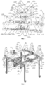
- the lifting device 110 may also consist of the first motor 111, a reducer 202, a coupling 203, a transmission shaft A204, a lifting sprocket A205, a guide post A206, a guide post D207, a transmission chain 208, a guide post B209, a guide post C210, a lifting sprocket B211, a transmission shaft B212, a lifting sprocket C213, a lifting sprocket D214 and the first frame body 112, wherein the first motor 111 is in matched connection with the reducer 202, the reducer 202 is fixed on the first frame body 112, one end of the transmission shaft A204 is connected to the reducer 202 through the coupling 203, the other end of the transmission shaft A204 is in matched connection with the lifting sprocket A205, the transmission shaft B212 is mounted on the first frame body 112, and two ends of the transmission shaft B212 are respectively in matched connection with the lifting sprocket B211,
- the cold-shrinkable film of the corresponding specification is selected based on the specification of the palletized article detected by the detector, and is stretched by the film continuation assemblies to cover the palletized article, so that the processing efficiency and adaptability of the film laminating machine are improved.
- the bearing assembly 120 further includes two push rods 122 and a variable frequency motor 123, wherein the two push rods 122 are oppositely arranged on both sides of the roller table 121, a drive shaft of the variable frequency motor 123 is in transmission connection with the two push rods 122, and the variable frequency motor 123 is configured to drive the two push rods 122 to move relatively close to or away from each other, so that the two push rods 122 can push the palletized article transported onto the roller table 121 to a middle position of the roller table 121.
- the palletized article may not be in the middle position of the roller table 121 during film lamination, resulting in incomplete film lamination or failure of the film lamination, thus, the two push rods 122 and the variable frequency motor 123 may be oppositely arranged on both sides of the roller table 121, and, when the palletized article reaches a corresponding film laminating region on the roller table 121, the variable frequency motor 123 drives the two push rods 122 to move relatively close to each other simultaneously, so as to correct the position of the palletized article on the roller table 121, to obtain a center position of the palletized article , thereby avoiding a process of manually correcting the palletized article position, and improving the degree of automation.
- a plurality of push rods may exist in one film laminating machine to cooperatively correct the position of the palletized article on the roller table 121, for convenience of description hereinafter, the push rods are classified into a push rod A1221 and a push rod B1222.
- the bearing assembly 120 may consist of the variable frequency motor 123, a worm gear reducer 502, a bracket A503, a transmission sprocket assembly A504, a bottom long chain 505, the roller table 121, a transmission sprocket assembly B507, a vertical chain A508, a transmission sprocket assembly C509, the push rod A1221, a horizontal chain A511, a transmission sprocket assembly D512, the palletized article 513, the push rod B1222, a transmission sprocket assembly E515, a horizontal chain B516, a bracket B517, and a vertical chain B.
- variable frequency motor 123 is in matched connection with the worm gear reducer 502, wherein, the worm gear reducer 502, the transmission sprocket assembly A504, and the transmission sprocket assembly E515 are fixed on the bracket A503; the transmission sprocket assembly B507, the transmission sprocket assembly C509 and the transmission sprocket assembly D512 are fixed on the bracket B517; the horizontal chain B516 is in matched connection with the transmission sprocket assembly E515 and the worm gear reducer 502 to drive the push rod B1222 to reciprocate; the vertical chain B is in matched connection with the transmission sprocket assembly E515 and the transmission sprocket assembly A504; the bottom long chain 505 is in matched connection with the transmission sprocket assembly A504 and the transmission sprocket assembly B507; the vertical chain A508 is in matched connection with the transmission sprocket assembly B507 and the transmission sprocket assembly D512;
- the film transporting device 130 further includes a funnel 133 and a suction assembly 134; the funnel 133 is arranged between the roller sets 131 and the film continuation assemblies 141, and an opening of the funnel 133 faces the roller sets 131; the suction assembly 134 is arranged at a film outlet of the funnel 133.
- the funnel 133 When in use, considering that the cold-shrinkable film is lighter, position deviation or winding may occur when the roller sets 131 rotate; thus, the funnel 133 may be arranged between the roller sets 131 and the film continuation assemblies 141, and the opening of the funnel 133 faces the roller sets 131; the film outlet of the funnel 133 corresponds to the positions of the film continuation assemblies 141; when the cold-shrinkable film on the roller set 131 is transported into the funnel 133, it can be ensured that the cold-shrinkable film is output from the film outlet of the funnel 133; meanwhile, considering that the two opposite film layers of the cold-shrinkable film are attached to each other, the suction assembly 134 may be arranged at the film outlet of the funnel 133; after the cold-shrinkable film is output from the film outlet of the funnel 133, the suction assembly 134 sucks the two opposite film layers of the cold-shrinkable film to enable the two opposite film layers to be separated.
- the suction assembly 134 includes a third motor, a first suction cup set and a second suction cup set; the third motor is electrically connected to the controller; the first suction cup set and the second suction cup set are oppositely arranged and are in transmission connection with the third motor; the third motor is configured to drive the first suction cup set and the second suction cup set to move close to or away from the cold-shrinkable film therebetween, so that the first suction cup set and the second suction cup set suck two opposite film layers of the cold-shrinkable film respectively to enable the two opposite film layers to be separated.
- each of the first suction cup set and the second suction cup set may be provided with one or more suction cups; and each of the suction cups in the first suction cup set is opposite to the corresponding suction cup in the second suction cup set; when the cold-shrinkable film is output from the film outlet of the funnel 133, the third motor drives the first suction cup set and the second suction cup set to move close to or away from the cold-shrinkable film therebetween, so that the first suction cup set and the second suction cup set suck two opposite film layers of the cold-shrinkable film respectively to enable the two opposite film layers to be separated.
- other structures capable of drawing or sucking the cold-shrinkable film such as an air extractor, may also be selected as the suction assembly 134.
- the film transporting device 130 further includes a static electricity elimination assembly 135 arranged between the film outlet of the funnel 133 and the suction assembly 134.
- the static electricity elimination assembly 135, such as an ion wind rod or an ion wind machine, may be arranged in a region between the film outlet of the funnel 133 and the suction assembly 134; before the cold-shrinkable film is output from the film outlet of the funnel 133, static electricity on the cold-shrinkable film is removed by the static electricity elimination assembly 135, which is convenient for the suction assembly 134 to subsequently suck and stretch the cold-shrinkable film.
- the film transporting device 130 further includes a heat-sealing assembly 136, the heat-sealing assembly 136 including a serrated knife, a knife groove, a first heat-sealing rod, a second heat-sealing rod and an air cylinder; the serrated knife and the air cylinder are both fixedly arranged between the static electricity elimination assembly 135 and the suction assembly 134; the first heat-sealing rod and the second heat-sealing rod are oppositely arranged below the serrated knife; the serrated knife is fixedly connected to a drive shaft of the air cylinder; the first heat-sealing rod and the second heat-sealing rod are relatively close to each other to clamp and heat the cold-shrinkable film; after the first heat-sealing rod and the second heat-sealing rod cooperatively perform heating and heat seal on the cold-shrinkable film, the air cylinder drives the serrated knife to move close to or away from the knife groove, such that the ser
- both the serrated knife and the air cylinder may be fixedly arranged above the suction assembly 134, and the first heat-sealing rod and the second heat-sealing rod are oppositely arranged between the serrated knife and the suction assembly 134;
- the serrated knife is fixedly connected to the drive shaft of the air cylinder;
- the first heat-sealing rod and the second heat-sealing rod cooperate with each other, so that the first heat-sealing rod and the second heat-sealing rod clamp the cold-shrinkable film; after heat seal of the cold-shrinkable film, the air cylinder can drive the serrated knife to move close to or away from the knife groove, such that the serrated knife cooperates with the knife groove to cut the cold-shrinkable film, thereby improving the stability during heat-sealing cutting.
- roller sets 131 may exist in one film laminating machine to transport cold-shrinkable films of different specifications; for convenience of description hereinafter, the roller sets 131 may be classified into a driven rubber-covered roller set A1311, a driving rubber-covered roller set A1312, a driving rubber-covered roller set B1313 and a driven rubber-covered roller set B1314.
- the film transporting device 130 may consist of the driven rubber-coated roller set A1311, a roller set support assembly A102, the driving rubber-covered roller set A1312, a roller set support assembly B104, the driving rubber-covered roller set B1313, a first-layer support profile A106, a support roller A107, a first-layer support profile B108, a support roller B109, a support roller C137, a support roller D138, the second motor 132, a long support profile A113, a long support profile B114, a roller set support assembly C115, the suction assembly 134, a suction cup A117, a suction cup B118, a suction cup C119, a suction cup D120, the heat-sealing assembly 136, the static electricity elimination assembly 135, a dragging chain A124, a dragging chain B125, a second-layer support profile A126, the funnel 133, a roller set support assembly D128, a second-layer support profile B129 and the driven rubber-coated roller set B131
- the roller set support assembly A102 is mounted on the first-layer support profile A106; the roller set support assembly D128 is mounted on the first-layer support profile B108; the driven rubber-covered roller set A1311 and the driving rubber-covered roller set A1312 are matched together with the roller set support assembly A102; the roller set support assembly B104 is mounted on the first-layer support profile A106; the roller set support assembly C115 is mounted on the second-layer support profile A126; the driving rubber-coated roller set B1313 and the driven rubber-coated roller set B1314 are matched together with the roller set support assembly B104; two ends of the suction assembly 134 and the suction assembly 134 are fixedly connected to the dragging chain A124 and the dragging chain B125, respectively; the suction cup A117 and the suction cup B118 are mounted on the suction assembly 134; the suction cup C119 and the suction cup D120 are mounted on the suction assembly 134; two ends of the heat-sealing assembly 136 are fixed onto the long support profile A113 and the
- the film stretching device 140 further includes a plurality of sliders 142 and a second frame body; each of the sliders 142 is connected to one of the film continuation assemblies 141; a roller is arranged on a surface of each slider 142 that is in contact with the second frame body, and is clamped onto the second frame body; the sliders 142 horizontally move along a sliding chute on the second frame body by means of the roller.
- the roller is a V-shaped wheel; a bearing pulley is arranged on each of two sides of the V-shaped wheel, and is arranged on a surface of each slider 142 that is in contact with the second frame body; the sliders 142 move along the second frame body by means of the bearing pulleys.
- a plurality of sliders 142 may be arranged on the second frame body; the second frame body may consist of a plurality of cross beams and a plurality of longitudinal beams, and the plurality of sliders 142 are arranged on the cross beams and the longitudinal beams, respectively, so that the cold-shrinkable film can be stretched by the plurality of film continuation assemblies 141 to have a size conforming to the size of the palletized article.
- the V-shaped wheel may be selected as the roller to reduce a friction force during sliding and facilitate assembling and disassembling.
- one bearing pulley may be arranged on each of two sides of the V-shaped wheel, and is arranged on a surface of each slider 142 that is in contact with the second frame body; the sliders 142 move along the second frame body by means of the bearing pulleys.
- the V-shaped wheel is supported by the bearing pulleys to cooperate with the sliding of the sliders 142 on the second frame body, thereby prolonging the service life of the machine.
- the film continuation assemblies 141 include a film continuation assembly A1411, a film continuation assembly B1412, a film continuation assembly C1413 and a film continuation assembly D1414.
- the sliders 142 include a hand-held slider A1421, a hand-held slider B1422, a hand-held slider C1423, a hand-held slider D1424, a hand-held slider E1425, a hand-held slider F1426, a hand-held slider G1427 and a hand-held slider H1428.
- the film stretching device 140 may consist of a driving chain A31, a cross beam A32, the hand-held slider A1421, the film continuation assembly A1411, a driving shaft A35, a guide wheel assembly A36, a lifting fixing part A37, a driving sprocket A38, a lifting fixing part B39, a driving chain A40, a cross beam B41, the hand-held slider B1422, a cross beam lifting part A43, a drive assembly A44, an idler assembly A45, an idler assembly B46, the hand-held slider C1423, a driving chain B48, a cross beam lifting part B49, a cross beam C50, an idler assembly C51, a longitudinal beam A52, a driving sprocket B53, a lifting fixing part C54, a lifting fixing part D55, a guide wheel assembly B56, a driving chain C57, a cross beam D58, a drive assembly B59, the hand-held slider D1424, the film continuation assembly B1412, an idler assembly D62
- the guide wheel assembly A36, the lifting fixing part B39, the lifting fixing part H82, the guide wheel assembly D85 and the drive assembly D90 are mounted on the cross beam A32; one end of the driving shaft A35 is in matched connection with the drive assembly D90, and the other end of the driving shaft A35 is in matched connection with the driving sprocket A38; one end of the driving shaft C83 is in matched connection with the drive assembly D90, and the other end of the driving shaft C83 is in matched connected with the driving sprocket C84; the lifting fixing part A37, the idler assembly A45, the idler assembly B46 and the lifting fixing part C54 are mounted on the longitudinal beam A52; the hand-held slider B1422 and the hand-held slider C1423 are matched with the longitudinal beam A52; one end surface of the cross beam lifting part A43 is fixedly connected to the hand-held slider B1422, and the other end surface of the cross beam lifting part A43 is fixedly connected to the cross beam B41; one end surface of the cross beam lifting part
- the film continuation assembly C1413 is mounted on the hand-held slider E1425; the driving chain D65 is in matched connection with the idler assembly D62 and the drive assembly C73; the driving sprocket C69, the lifting fixing part F70, the idler assembly E75, the idler assembly F76 and the lifting fixing part 186 are mounted on the longitudinal beam B80; the driving chain E71 is in matched connection with the driving sprocket C69 and the idler assembly E75 to drive the hand-held slider F1426 to reciprocate on the longitudinal beam B80; one end of the beam lifting part C72 is fixed to the longitudinal beam B80, and the other end of the beam lifting part C72 is fixed to the cross beam C50; one end of the cross beam lifting part D77 is fixed to the longitudinal beam B80, and the other end of the cross beam lifting part D77 is fixedly connected to the cross beam B41; one end of the driving shaft C83 is in matched connection with the drive assembly D90, and the other end of the driving shaft C83 is in matched connection with the driving
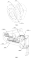
- the idler assembly B consists of an idler shaft 4601, an idler 4602, and a clamp spring 4603; the idler 4602 and the idler shaft 4601 are mounted in a matched manner, and the clamp spring 4603 tightly clamps the idler 4602.
- the film continuation assembly 141 includes pulling claws and a fourth motor; the pulling claws are fixedly arranged on the corresponding slider 142; a drive shaft of the fourth motor is in transmission connection with the slider 142; the fourth motor is configured to drive the slider 142 to move along the third frame body after the pulling claws clamp the cold-shrinkable film.
- the pulling claws clamp the cold-shrinkable film.
- the fourth motor drives the slider 142 to move along the third frame body, so that the plurality of pulling claws can cooperatively stretch the cold-shrinkable film to have a size corresponding to the palletized article.
- each film continuation assembly 141 may consist of a pulling claw fixing part 3401, pulling claws 3402, a small drive motor 3403, a rodless cylinder 3404, a small reducer 3405, and a rubber-covered drive wheel 3406; the pulling claws 3402 and the rodless cylinder 3404 are fixed onto the pulling claw fixing part 3401; the small reducer 3405 is mounted on the rodless cylinder 3404; the small drive motor 3403 is in matched connection with the small reducer 3405; the rubber-covered drive wheel 3406 is fixedly connected to the small reducer 3405.
- the film laminating machine provided by the above embodiments of the present disclosure is suitable for automated assembly line operations.
- the bearing assembly is configured to bear a palletized article to be laminated with a film
- the detector is configured to detect a specification of the palletized article
- the controller selects a matching roller set in the film transporting device based on the specification of the palletized article detected by the detector, controls the film stretching device to stretch the cold-shrinkable film output from the roller set, and enable the cold-shrinkable film to cover the palletized article, so that the processing efficiency and the adaptability of the film laminating machine are improved.
- the embodiments of the present disclosure further provide a method for using a film laminating machine; the method includes the following steps:
- the cold-shrinkable film is stretched by film continuation assemblies of the film stretching device to have a specification corresponding to the palletized article.
- the film stretching device may include the plurality of film continuation assemblies which can clamp the cold-shrinkable film and simultaneously stretch the cold-shrinkable film in different directions, so that the cold-shrinkable film is stretched to have a size corresponding to the palletized article. For example, if the specification of the palletized article is 1m ⁇ 0.8m, the film continuation assemblies are controlled to stretch the cold-shrinkable film to have a size of 1m ⁇ 0.8m or 1.1m*0.9m to ensure that the cold-shrinkable film can cover the palletized article.
- a third frame body of the film stretching device is driven by a first motor of the lifting device to move close to the palletized article, so as to cover the palletized article with the cold-shrinkable film.
- the first motor of the lifting device drives the third frame body of the film stretching device to move close to the palletized article, so as to cover the palletized article with the cold-shrinkable film.
- the first motor may also drive the third frame body of the film stretching device to move close to the palletized article, and then, the cold-shrinkable film is stretched.
- the matching cold-shrinkable film is selected based on the detected palletized articles of different specifications to perform lamination and coverage, so that the efficiency and the adaptability of the film lamination are improved.
- the cold-shrinkable film of the corresponding specification is selected based on the specification of the palletized article detected by the detector, and is stretched by the film continuation assemblies to cover the palletized article, so that the processing efficiency and the adaptability of the film laminating machine are improved.
Landscapes
- Engineering & Computer Science (AREA)
- Mechanical Engineering (AREA)
- Lining Or Joining Of Plastics Or The Like (AREA)
Applications Claiming Priority (2)
| Application Number | Priority Date | Filing Date | Title |
|---|---|---|---|
| CN202010833799.8A CN111846325A (zh) | 2020-08-18 | 2020-08-18 | 一种覆膜机及其使用方法 |
| PCT/CN2021/085288 WO2022037077A1 (fr) | 2020-08-18 | 2021-04-02 | Machine de stratification de film et son procédé d'utilisation |
Publications (2)
| Publication Number | Publication Date |
|---|---|
| EP4201825A1 true EP4201825A1 (fr) | 2023-06-28 |
| EP4201825A4 EP4201825A4 (fr) | 2024-12-11 |
Family
ID=72970284
Family Applications (1)
| Application Number | Title | Priority Date | Filing Date |
|---|---|---|---|
| EP21798262.8A Pending EP4201825A4 (fr) | 2020-08-18 | 2021-04-02 | Machine de stratification de film et son procédé d'utilisation |
Country Status (3)
| Country | Link |
|---|---|
| EP (1) | EP4201825A4 (fr) |
| CN (1) | CN111846325A (fr) |
| WO (1) | WO2022037077A1 (fr) |
Families Citing this family (8)
| Publication number | Priority date | Publication date | Assignee | Title |
|---|---|---|---|---|
| CN111846325A (zh) * | 2020-08-18 | 2020-10-30 | 上海飒智智能科技有限公司 | 一种覆膜机及其使用方法 |
| CO2021010489A1 (es) * | 2021-08-10 | 2021-11-19 | Mekatronica Mx S A S | Dispositivo roll stand compacto para bobinas de material flexible |
| CN115231018B (zh) * | 2022-05-27 | 2023-07-07 | 苏州立德麦自动化有限公司 | 一种细菌培养皿的打包装置及方法 |
| CN115123604B (zh) * | 2022-06-22 | 2024-02-20 | 中建材(宜兴)新能源有限公司 | 一种光伏玻璃自动打包流水线 |
| CN115924178B (zh) * | 2022-12-01 | 2023-06-23 | 杭州宏振玮业科技有限公司 | 一种电能计量箱盖板的覆膜装置 |
| CN115973517A (zh) * | 2022-12-17 | 2023-04-18 | 常州瑞致机电科技有限公司 | 一种套膜机 |
| CN116654351A (zh) * | 2023-06-06 | 2023-08-29 | 颖态智能技术(上海)有限公司 | 一种基于图像处理的冷拉伸套膜机的套膜装置 |
| CN118083213B (zh) * | 2024-04-29 | 2024-06-21 | 常州海天石化配件有限公司 | 一种四氟垫片生产用输送包装机构 |
Family Cites Families (12)
| Publication number | Priority date | Publication date | Assignee | Title |
|---|---|---|---|---|
| CN2717823Y (zh) * | 2004-05-08 | 2005-08-17 | 天珩机械股份有限公司 | 收缩膜自动套袋机的送袋装置膜座及导正结构 |
| CN101830293B (zh) * | 2010-05-12 | 2012-11-21 | 哈尔滨博实自动化股份有限公司 | 通用型拉伸套膜包装机 |
| CA3093344C (fr) * | 2012-06-08 | 2023-03-28 | Wulftec International Inc. | Appareil pour emballer une charge et fournir une pellicule pour emballer une charge et procedes associes |
| CN102689706B (zh) * | 2012-06-14 | 2016-06-29 | 长沙长泰智能装备有限公司 | 侧置式顶膜覆盖机 |
| CN105905370A (zh) * | 2016-06-17 | 2016-08-31 | 锐派包装技术(上海)有限公司 | 一种冷拉式套膜机 |
| CN106379616B (zh) * | 2016-09-23 | 2018-09-21 | 奇瑞汽车股份有限公司 | 一种包装流水线及其控制方法 |
| CN107298199B (zh) * | 2017-06-06 | 2019-09-10 | 佛山宝钢不锈钢贸易有限公司 | 一种同步多规格钢板覆膜机及留边覆膜钢板加工方法 |
| CN207157607U (zh) * | 2017-08-07 | 2018-03-30 | 广州市永兴自动化机械科技有限公司 | 在线缠膜机 |
| CN208007340U (zh) * | 2018-03-14 | 2018-10-26 | 纪焕钊 | 一种冷拉伸套膜包装机 |
| CN209701054U (zh) * | 2019-03-11 | 2019-11-29 | 佛山市顺德彩辉纺织有限公司 | 一种pe膜布匹包装机 |
| CN111846325A (zh) * | 2020-08-18 | 2020-10-30 | 上海飒智智能科技有限公司 | 一种覆膜机及其使用方法 |
| CN212606001U (zh) * | 2020-08-18 | 2021-02-26 | 上海飒智智能科技有限公司 | 一种覆膜机 |
-
2020
- 2020-08-18 CN CN202010833799.8A patent/CN111846325A/zh active Pending
-
2021
- 2021-04-02 WO PCT/CN2021/085288 patent/WO2022037077A1/fr not_active Ceased
- 2021-04-02 EP EP21798262.8A patent/EP4201825A4/fr active Pending
Also Published As
| Publication number | Publication date |
|---|---|
| CN111846325A (zh) | 2020-10-30 |
| WO2022037077A1 (fr) | 2022-02-24 |
| EP4201825A4 (fr) | 2024-12-11 |
Similar Documents
| Publication | Publication Date | Title |
|---|---|---|
| EP4201825A1 (fr) | Machine de stratification de film et son procédé d'utilisation | |
| CN108152305B (zh) | 一种x-ray无损检测设备 | |
| CN107499563B (zh) | 多工位晶体振荡器测试分类打标编带一体设备 | |
| CN104505486B (zh) | 一种圆柱电池自动焊盖帽机 | |
| KR20090114257A (ko) | 자동 용기 실링 장치 | |
| CN103879754A (zh) | 送料装置 | |
| CN110697612A (zh) | 一种输送盘机 | |
| CN110355021A (zh) | 一种面板灯消除亮边的装置和方法 | |
| CN212606001U (zh) | 一种覆膜机 | |
| CN105984729A (zh) | 全自动玻璃水平堆垛机和玻璃堆垛方法 | |
| CN116477142A (zh) | 一种电性能检测贴膜设备 | |
| CN206345042U (zh) | 一种货物码垛后的自动捆扎设备 | |
| CN111994333B (zh) | 一种钣金件出库打包自动薄膜缠绕机 | |
| CN205159346U (zh) | Epe膜自动供给装置和叠焊机 | |
| CN110682540B (zh) | 全自动透气垫片焊接机 | |
| CN207344108U (zh) | 一种铁芯组件自动装配机 | |
| CN212100828U (zh) | 一种自动上下料装置 | |
| CN212220655U (zh) | 一种基于视觉识别的智能制造编带设备 | |
| CN218225458U (zh) | 一种定子绝缘片组装设备 | |
| CN104551688B (zh) | 焊接装置 | |
| CN109177322A (zh) | 一种绕带封袋机 | |
| CN210824478U (zh) | 一种面料收料装置 | |
| CN111791498A (zh) | 一种自动铆合设备 | |
| CN111591532A (zh) | 一种基于视觉识别的智能制造编带设备 | |
| CN115783431B (zh) | 一种智能纸塑袋包装机 |
Legal Events
| Date | Code | Title | Description |
|---|---|---|---|
| STAA | Information on the status of an ep patent application or granted ep patent |
Free format text: STATUS: UNKNOWN |
|
| STAA | Information on the status of an ep patent application or granted ep patent |
Free format text: STATUS: THE INTERNATIONAL PUBLICATION HAS BEEN MADE |
|
| PUAI | Public reference made under article 153(3) epc to a published international application that has entered the european phase |
Free format text: ORIGINAL CODE: 0009012 |
|
| STAA | Information on the status of an ep patent application or granted ep patent |
Free format text: STATUS: REQUEST FOR EXAMINATION WAS MADE |
|
| 17P | Request for examination filed |
Effective date: 20220126 |
|
| AK | Designated contracting states |
Kind code of ref document: A1 Designated state(s): AL AT BE BG CH CY CZ DE DK EE ES FI FR GB GR HR HU IE IS IT LI LT LU LV MC MK MT NL NO PL PT RO RS SE SI SK SM TR |
|
| DAV | Request for validation of the european patent (deleted) | ||
| DAX | Request for extension of the european patent (deleted) | ||
| A4 | Supplementary search report drawn up and despatched |
Effective date: 20241113 |
|
| RIC1 | Information provided on ipc code assigned before grant |
Ipc: B65B 61/00 20060101ALI20241107BHEP Ipc: B65B 11/58 20060101AFI20241107BHEP |