EP4201867A1 - Windenanordnung zur unterstützung der bewegung eines kettenfahrzeugs und zugehöriges steuerungsverfahren - Google Patents
Windenanordnung zur unterstützung der bewegung eines kettenfahrzeugs und zugehöriges steuerungsverfahren Download PDFInfo
- Publication number
- EP4201867A1 EP4201867A1 EP22213865.3A EP22213865A EP4201867A1 EP 4201867 A1 EP4201867 A1 EP 4201867A1 EP 22213865 A EP22213865 A EP 22213865A EP 4201867 A1 EP4201867 A1 EP 4201867A1
- Authority
- EP
- European Patent Office
- Prior art keywords
- signal
- winch
- pressure
- pull force
- control
- Prior art date
- Legal status (The legal status is an assumption and is not a legal conclusion. Google has not performed a legal analysis and makes no representation as to the accuracy of the status listed.)
- Granted
Links
Images


Classifications
-
- B—PERFORMING OPERATIONS; TRANSPORTING
- B66—HOISTING; LIFTING; HAULING
- B66D—CAPSTANS; WINCHES; TACKLES, e.g. PULLEY BLOCKS; HOISTS
- B66D1/00—Rope, cable, or chain winding mechanisms; Capstans
- B66D1/28—Other constructional details
- B66D1/40—Control devices
- B66D1/48—Control devices automatic
- B66D1/485—Control devices automatic electrical
-
- B—PERFORMING OPERATIONS; TRANSPORTING
- B66—HOISTING; LIFTING; HAULING
- B66D—CAPSTANS; WINCHES; TACKLES, e.g. PULLEY BLOCKS; HOISTS
- B66D1/00—Rope, cable, or chain winding mechanisms; Capstans
- B66D1/02—Driving gear
- B66D1/08—Driving gear incorporating fluid motors
-
- B—PERFORMING OPERATIONS; TRANSPORTING
- B66—HOISTING; LIFTING; HAULING
- B66D—CAPSTANS; WINCHES; TACKLES, e.g. PULLEY BLOCKS; HOISTS
- B66D1/00—Rope, cable, or chain winding mechanisms; Capstans
- B66D1/28—Other constructional details
-
- B—PERFORMING OPERATIONS; TRANSPORTING
- B66—HOISTING; LIFTING; HAULING
- B66D—CAPSTANS; WINCHES; TACKLES, e.g. PULLEY BLOCKS; HOISTS
- B66D1/00—Rope, cable, or chain winding mechanisms; Capstans
- B66D1/28—Other constructional details
- B66D1/36—Guiding, or otherwise ensuring winding in an orderly manner, of ropes, cables, or chains
-
- B—PERFORMING OPERATIONS; TRANSPORTING
- B66—HOISTING; LIFTING; HAULING
- B66D—CAPSTANS; WINCHES; TACKLES, e.g. PULLEY BLOCKS; HOISTS
- B66D1/00—Rope, cable, or chain winding mechanisms; Capstans
- B66D1/28—Other constructional details
- B66D1/40—Control devices
- B66D1/48—Control devices automatic
- B66D1/50—Control devices automatic for maintaining predetermined rope, cable, or chain tension, e.g. in ropes or cables for towing craft, in chains for anchors; Warping or mooring winch-cable tension control
- B66D1/505—Control devices automatic for maintaining predetermined rope, cable, or chain tension, e.g. in ropes or cables for towing craft, in chains for anchors; Warping or mooring winch-cable tension control electrical
-
- E—FIXED CONSTRUCTIONS
- E01—CONSTRUCTION OF ROADS, RAILWAYS, OR BRIDGES
- E01H—STREET CLEANING; CLEANING OF PERMANENT WAYS; CLEANING BEACHES; DISPERSING OR PREVENTING FOG IN GENERAL CLEANING STREET OR RAILWAY FURNITURE OR TUNNEL WALLS
- E01H4/00—Working on surfaces of snow or ice in order to make them suitable for traffic or sporting purposes, e.g. by compacting snow
- E01H4/02—Working on surfaces of snow or ice in order to make them suitable for traffic or sporting purposes, e.g. by compacting snow for sporting purposes, e.g. preparation of ski trails; Construction of artificial surfacings for snow or ice sports ; Trails specially adapted for on-the-snow vehicles, e.g. devices adapted for ski-trails
-
- B—PERFORMING OPERATIONS; TRANSPORTING
- B66—HOISTING; LIFTING; HAULING
- B66D—CAPSTANS; WINCHES; TACKLES, e.g. PULLEY BLOCKS; HOISTS
- B66D2700/00—Capstans, winches or hoists
- B66D2700/01—Winches, capstans or pivots
- B66D2700/0125—Motor operated winches
- B66D2700/0133—Fluid actuated
Definitions
- the invention relates to a winch assembly for assisting the movement of a tracked vehicle, in particular a snow groomer, along steep slopes and to the relative control method.
- a tracked vehicle comprises a frame; a vehicle control unit; and the winch assembly, which, in turn, comprises a support structure; a rotary drum, which can rotate relative to the support structure; a cable, which can be wound and unwound around the drum; an actuator assembly, which is coupled to the drum so as to cause the drum to rotate around the axis; and a winch control device, which is coupled to the actuator assembly in order to control the actuator assembly so as to adjust the winding and unwinding of the cable.
- a tracked vehicle of the snow groomer kind also comprises a tiller to process the snowpack of ski slopes and a shovel to move snow masses along ski slopes.
- the free end of the cable of the winch assembly is fixed to an upstream anchorage, so as to operate the traced vehicle with the help of the winch assembly and ensure greater safety as well as prevent the tracked vehicle from skidding in case it loses its grip on the snow surface.
- Document EP 1 118 580 discloses a method to control the winch assembly so that the pull force of the cable changes depending on the difference in pressure values between the two pumps supplying the tracks of the snow groomer and on the angle of the arm of the winch relative to the travel direction.
- control method works well within some limits, but is not very appropriate in case short reaction times are requested and a strong resistance to internal and external disturbances is needed.
- An object of the invention is to provide a winch assembly capable of overcoming at least one of the drawbacks of the prior art.
- the winch assembly ensures precision in the control of the pull force even for high pull force values as well as short reaction times, so as to counter sudden external load changes due to sudden changes in the ground or to sudden changes in the load of the tracked vehicle.
- the winch assembly is insensitive to internal or external disturbances in the control of the pull force of the winch and provides a pull force control system having quick and stable dynamics. More in detail, thanks to the invention, the control of the pull force is capable of quickly reacting to operator's commands and/or to load changes due to external causes.
- the first control signal involved in the adjustment of the pull force of the winch assembly is a signal controlled in open loop relative to the pull force; by so doing, a load cell is no longer needed like in the prior art and this avoids potential oscillations or instabilities of the control system, besides making the control system more simple, economic and intrinsically sturdy.
- the pull force is adjusted based on the pull direction and on the travel direction, in particular the pull force is limited in some circumstances.
- control device ensures a more precise, quick and stable adjustment of the pull force; as a matter of fact, with the value of the wound rope length it is possible to better adjust the torque to be applied to the drum to determine a pull force.
- the winch assembly comprises a variable displacement motor coupled to the hydraulic circuit and supplied by the variable displacement pump through the hydraulic circuit; the variable displacement motor being configured to vary its displacement based on the pressure detected on the hydraulic circuit.
- Another object of the invention is to provide a tracked vehicle capable of reducing the drawbacks of the prior art.
- a tracked vehicle comprising an engine assembly, preferably an internal combustion engine, a first and second track and a winch assembly according to any one of the claims from 1 to 13.
- Another object of the invention is to provide a method for operating a winch assembly for a tracked vehicle capable of reducing at least one of the drawbacks of the prior art.
- number 1 defines, as a whole, a tracked vehicle.
- the tracked vehicle 1 is a snow groomer for the preparation of ski slopes.
- the tracked vehicle 1 comprises a frame 2; two tracks 3 (only one of them is shown in figure 1 ); two drive wheels 4 (only one of them is shown in figure 1 ), which are operatively coupled to the respective tracks 3; a cabin 6; a user interface 7 arranged in the cabin 6; a shovel 8, which is supported by the frame 2 at the front; a tiller 9, which is supported by the frame 2 at the back; a winch assembly 10, which is fixed to the frame 2; an engine assembly 11; and a powertrain 12 (partially visible in figure 3 ), which is operatively connected to the engine assembly 11, to the drive wheels 4, to the shovel 8, to the miller 9. Furthermore, the powertrain 12 connects the engine assembly 11 to the winch assembly 10.
- the tracked vehicle 1 only comprises either the shovel 8 or the tiller 9. In other words, either the shovel 8 or the tiller 9 can be left out.
- the engine assembly 11 comprises an internal combustion engine. In another preferred embodiment, the engine assembly 11 comprises one or more electric machines and, preferably, power supply batteries. In another preferred embodiment, the engine assembly 11 comprises one or more electric machines and at least one internal combustion engine, so as to form a hybrid engine assembly 11 of the series or parallel kind or of another kind. In another preferred embodiment, the engine assembly 11 comprises fuel cells and, preferably, one or more electric motors.
- the powertrain 12 can be hydraulic or electric or a combination of hydraulic and electric.
- the tracked vehicle 1 comprises a vehicle control unit 13, which is connected to the user interface 7 and is designed to control the tracked vehicle 1.
- the winch assembly 10 comprises a winch control device 13a configured to control the winch assembly 10. Furthermore, the winch control device 13a is connected to the user interface 7.
- the tracked vehicle 1 comprises a first pump (not visible in the accompanying figures) to operate one of the tracks 3 and a second pump (not visible in the accompanying figures) to operate the other track 3.
- the tracked vehicle 1 comprises a first electric machine to operate one of the tracks 3 and a second electric machine to operate the other track 3.
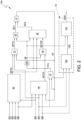
- the winch assembly 10 comprises a support structure 14, which is fixed to the frame 2, a rotary drum 15, which can rotate relative to the support structure 14 around an axis A; a cable 16, which has an end fixed to the drum 15 and is wound around the drum 15; an actuator assembly 17 ( figure 3 ) coupled to the drum 15 so as to wind or unwind the cable 16 through a pull force; and the winch control device 13a coupled to the actuator assembly 17 to control the pull force of the cable 16.
- the winch control device 13a being configured to determine and emit a first control signal SC1 and a second control signal SC2 to control the actuator assembly 17.
- the actuator assembly 17 is configured to receive the first control signal SC1 and the second control signal SC2 from the winch control device 13a and to be controlled by the winch control device 13a through the first control signal SC1 and the second control signal SC2.
- the actuator assembly 17 comprises a hydraulic circuit 20, a variable displacement pump 21, which supplies the hydraulic circuit, and a variable displacement motor 22, which is supplied by the variable displacement pump 21 through the hydraulic circuit 20.
- the actuator assembly 17 comprises a hydraulic shutter valve 24, whose inlet is connected to the high-pressure branch of the hydraulic circuit. Furthermore, the shutter valve 24 is connected to the winch control device 13a so as to receive and be controlled by means of the first control signal SC1. The shutter valve adjusts its outlet based on the first control signal SC1.
- the variable displacement pump 21 comprises a pump control unit 21a to change its displacement.
- the pump control unit 21a comprises a hydraulic input connected to the outlet of the shutter valve 24 and an electric input configured to receive an electric signal and connected to the winch control device 13a in order to receive the second control signal C2. More in detail, the pump control unit 21a is configured to vary the displacement of the variable displacement pump 21 based on the pressure values received through the hydraulic input and on the value of the electric signal received by the electric input; more in detail, the pump control unit 21a adjusts the displacement of the variable displacement pump 21 based on the smaller value between the pressure value and the value of the electric signal.
- the second control signal SC2 is omitted or has a fixed value always equal to the maximum value possible; in this case, the pump control unit 21a adjusts the displacement of the variable displacement pump 21 based on the pressure value received by the hydraulic input.
- the first control signal SC1 is omitted or has a fixed value always equal to the maximum value possible; in this case, the pump control unit 21a adjusts the displacement of the variable displacement pump 21 based on the displacement value received indicated by the second control signal SC2.
- the variable displacement motor 22 comprises a motor control unit 22a, which is configured to adjust the displacement of the variable displacement motor 22.
- the motor control unit 22a is connected to the high pressure branch of the hydraulic circuit 20 as to receive, as an input, the liquid under pressure and adjust the displacement of the variable displacement motor 22 based on the pressure of the high pressure branch of the hydraulic circuit 20.
- the variable displacement motor 22 is configured to vary its displacement based on the pressure of the high pressure branch of the hydraulic circuit 20.
- the pressure of the hydraulic circuit as discussed above, is adjusted depending on the first control signal SC1.
- the variable displacement motor 22 is configured to vary its displacement based on the first control signal SC1.
- variable displacement motor 22 is coupled to the drum 15 and acts upon the drum 15 in order to adjust the pull force of the rope 16.
- the user interface 7 is coupled to the winch control device 13a and allows a desired force control, which is received from the operator U, to be sent. More in detail, the user interface 77 is configured to emit a desired force signs S4 based on the desired force control received from the operator U.
- the winch control device 13a comprises a pressure sensor 28, which is coupled to the high pressure branch of the hydraulic circuit 20 to detect the pressure of the hydraulic circuit 20 and emit a measured pressure signal PF, which is an electric signal indicative of the pressure of the high pressure branch of the hydraulic circuit 20.
- the tracked vehicle 1 comprises a speed sensor (not shown in the accompanying figures) to measure the travel speed of the tracked vehicle 1.
- the speed sensor is coupled to the winch control device 13a in order to determine and send to the winch control device 13a a measured travel speed signal S2 indicative of the measured travel speed.
- the winch assembly 10 comprises a rope speed sensor (not shown in the accompanying figures) coupled to rope 16 to measure the moving speed of the rope 16 and determine a measured rope speed signal S3 indicative of the measured rope speed S3 to be sent to the winch control device 13a.
- the rope speed sensor is coupled to the drum, measures the rotations of the drum and sends the number of rotations of the drum to the winch control device.
- the winch assembly 10 comprises a wound rope sensor coupled to the rope to measure the quantity of rope wound around the drum.
- the wound rope sensor determines and sends to the winch control device a rope a measured wound rope length signal S7.
- the wound rope sensor comprises a calculation unit, which calculates the quantity of wound rope based on the number of positive or negative revolutions of the drum.
- the sensor detecting the revolutions of the drum can be part of the wound rope sensor or be a separate sensor.
- the winch assembly 10 comprises an angle sensor coupled to an arm 5 of the winch assembly 10 to measure the angle formed by the arm 5 of the winch assembly 10 with a travel direction D of the tracked vehicle.
- the angle sensor determines and sends to the winch control device 13a a measured angle signal S5.
- the arm 5 is fixed to the support structure 14 and can rotate around a vertical axis B.
- the arm 5 is coupled to the drum 15 and guides the rope 16.
- the tracked vehicle 1 comprises a pressure sensor (not shown in the accompanying figures) coupled to the first and to the second pump (not shown) of the one of the tracks 3 and of the other track 3, respectively, in particular coupled to the hydraulic circuit of the first pump and to the hydraulic circuit of the second pump.
- the pressure sensor is configured to define a measured track pressure signal S1 indicative of the pressure difference between the two hydraulic circuits of the two tracks 3.
- the track pressure signal S1, the measured travel speed signal S2, the rope speed signal S3, the desired force signal S4, the measured angle signal S5, the wound rope length signal S7, the measured pressure signal PF are electric signals.
- the winch control device 13a is configured to determine the first and the second control signal SC1 and SC2 based on the measured travel speed signal S2 of the tracked vehicle 1, on the measured pressure signal PF, on the rope speed signal S3, on the wound rope length signal S7, on the measured angle signal S5 and on the desired force signal S4.
- the winch control device 13a defines the first control signal SC1 based on the measured angle signal S5, on the rope speed signal S3, on the wound rope signal S7, on the measured travel speed signal S2, on the measured pressure signal PF and on the desired pull force signal S4.
- the winch control device 13a defines the first control signal SC1 based on the track pressure signal S1.
- the winch control device 13a defines the second control signal SC2 based on the measured angle signal S5, on the wound rope signal S7, on the measured travel speed signal S2, on the measured pressure signal PF, on the rope speed signal S3 and, preferably, on the desired pull force signal S4 and/or on the track pressure signal S1.
- the tracked vehicle 1 comprises an engine revolution sensor coupled to the engine assembly 11 and defining a measured engine revolution signal S6 indicative of a number of measured revolutions of the engine assembly 11 of the tracked vehicle 1.
- the engine revolution signal S6 is an electric signal.
- the winch control device 13a defines the second control signal SC2 based on the engine revolution signal S6 in addition to the signals indicated above.
- one or more of the signals listed above are omitted in the determination of the control signal SC1 and of the second control signal SC2 by the winch control device 13a.
- the winch control device 13a does not define the second control signal SC2 or it defines it with a fixed and non-variable value based on the signals listed above. In this case, the winch control device 13a defines the second control signal SC2 as equal to the maximum possible value of the control signal SC2.
- an embodiment of the invention comprises a winch control device 13a which only determines the first control signal SC1 in the ways discussed above.
- the winch control device 13a does not define the first control signal SC1 or it defines it with a fixed and non-variable value based on the signals listed above. In this case, the winch control device 13a defines the first control signal SC1 as equal to the maximum possible value of the control signal SC1.
- an embodiment of the invention comprises a winch control device 13a which only determines the second control signals SC2 in the ways discussed above.
- the winch control device 13a determines the first and/or the second control signals SC1 and SC2 according to the following paragraphs.
- the winch control device 13a comprises a calculation unit 30 configured to calculate a desired theoretical force signal SFTD indicative of a desired theoretical pull force value.
- the control unit 30 receives, as an input, the measured angle signal S5, the rope speed signal S3, the desired pull force signal S4, the measured travel speed signal S2 and defines the desired theoretical force signal SFTD based on the input signals.
- the calculation unit 30 receives, as an input, the track pressure signal S1 and defines the desired theoretical force signal SFTD also based on said signal together with the signals listed above.
- the winch control device 13a comprises a calculation unit 31 connected to the calculation unit 30.
- the calculation unit 31 receives, as an input, the desired theoretical force signal SFTD, the wound rope signal S7 and the measured pressure signal PF and determines a desired theoretical pressure signal SPTD.
- the winch control device 13a comprises a frequency-adjustable active filter 32 and an oscillation detector 33 configured to receive, as an input, a calculated pull force signal FFC and to provide, as an output, a filtering signal SF indicative of one or more frequency values, if an oscillation on the calculated force signal FFC is detected.
- the oscillation detector 33 is configured to detect oscillations through the detection of frequencies related to harmonics having amplitude values greater than a given value and within a first detection frequency range. To this aim, the oscillation detector 33 can perform a FFT or a DFT or be equipped with other electronic means to detect harmonics exceeding a given amplitude and within a first detection frequency range.
- the calculated pull force signal FFC is calculated based on the wound rope length signal S7 and on the measured pressure signal PF.
- the calculated pull force signal FFC is an electric signal.
- the snow groomer 1 does not comprise a force sensor, in particular a load cell, coupled to the rope 16 in order to detect the pull force exhibited by the rope 16, but the pull force is calculated through the wound rope length signal S7 and the measured pressure signal PF.
- the winch control device 13a comprises a control unit 37, which receives, as an input, the wound rope length signal S7 and the measured pressure signal PF and provides, as an output, a calculated pull force signal FFC indicative of the pull force on the rope 16.
- the invention eliminates the problems caused by the measurement of the pull force through a force sensor, in particular a lead cell, as well as the oscillations of said measurement, which, in the prior art, can cause instability in the feedback of the control of the pull force. Thanks to the calculation of the pull force instead of the measurement, the control system is more stable and does not cause oscillations or instability in the controlled system. In other words, thanks to the invention, a perfect control of the pull force is obtained without the disadvantages of the feedback on the control of the pull force.
- the active filter 32 is frequency-adjusted based on the frequency or on the frequencies detected by the oscillation detector 33 so as to dampen or eliminate oscillations in the measured pressure PF or in the calculated pull force FFC.
- the active filter 32 receives, as an input, the filtering signal SF and the desired theoretical pressure signal SPTD and determines, as an output, the control signal SC1.
- the control signal SC1 is defined based on the desired theoretical pressure signal SPTD and filtered from possible oscillations indicated by the filtering signal SF.
- the winch control device 13a comprises a calculation unit 34, which receives, as an input, the measured travel speed signal S2, the wound rope length signal S7, the measured angle signal S5, the measured pressure signal PF and provides, as an output, a desired theoretical displacement signal SCTD calculated based on the input signals.
- the calculation unit 34 receives, as in input, the engine revolution signal S6 and defines the desired theoretical displacement signal SCTD in addition to the signals listed above.
- the winch control device 13a comprises a frequency-adjustable active filter 35 connected to the oscillation detector 33.
- the active filter 35 is frequency-adjusted based on the frequency or on the frequencies detected by the oscillation detector 33 so as to dampen or eliminate oscillations in the measured pressure PF or in the calculated pull force FFC.
- the active filter 35 receives, as an input, the desired theoretical displacement signal SCTD and the filtering signal SF and determines a filtered desired theoretical displacement signal SCTDF.
- the filtered desired theoretical displacement signal SCTDF is determined based on the desired theoretical displacement signal SCTD and filtered from the oscillation indicated in the filtering signal SF.
- the winch control device 13a comprises a calculation unit 36, which receives, as an input, the filtered desired theoretical displacement signal SCTDF, the filtering signal SF, the calculated pull force signal FFC and the desired theoretical force signal SFTD and defines, as an output, the second control signal SC2 based on the input signals.
- the vehicle control unit 13 is configured to define a forward command signal DDC based on the engine revolution number signal S6, on the wound rope length signal S7, on the measured pressure signal PF and on the filtering signal SF.
- the vehicle control unit 13 is connected to the winch control device 13a so as to define the forward command signal DDC.
- the vehicle control unit 13 comprises a processing unit 13b and a processing unit 13c.
- the processing unit 13b receives, as an input, the engine revolution number signal S6, the wound rope length signal S7, the measured pressure signal PF and determines a speed limit signal VSL initiating the maximum speed that can be reached by the tracked vehicle 1.
- the processing unit 13c is connected to the processing unit 13b and receives, as an input, the speed limit signal VSL and the filtering signal SF and defines the forward command signal DDC, which causes the snow groomer 1 to move forward.
- the forward command signal DDC can control the tracks of the snow groomer so as to define the forward movement of the snow groomer 1.
- control signal SC1 adjusts the pull force of the winch assembly 10 by means of a control consisting of an electronic open-loop control relating to the pull force, connected in series to a feedback hydraulic control on the pressure of the hydraulic circuit 20.
- the electronic open-loop control is stable and insensitive to internal and external disturbances and/or to control variations and/or to load variations thanks to the adjustable active filtering and to the oscillation detector.
- the pull force and the pull speed are adjusted in an independent manner and by means of two electronic controls, which are in series to the feedback hydraulic control.
- This type of control ensures the advantages discussed above, in addition to the advantage of having a very precise and stable control on the pull force and on the pull speed, even for high values and even for quick dynamics due to sudden load changes. Moreover, this type of control reduces consumptions.
Landscapes
- Engineering & Computer Science (AREA)
- Mechanical Engineering (AREA)
- Architecture (AREA)
- Civil Engineering (AREA)
- Structural Engineering (AREA)
- Fluid-Pressure Circuits (AREA)
- Placing Or Removing Of Piles Or Sheet Piles, Or Accessories Thereof (AREA)
- Jib Cranes (AREA)
- Control And Safety Of Cranes (AREA)
- Control Of Fluid Gearings (AREA)
Applications Claiming Priority (1)
| Application Number | Priority Date | Filing Date | Title |
|---|---|---|---|
| IT102021000032639A IT202100032639A1 (it) | 2021-12-24 | 2021-12-24 | Gruppo verricello di ausilio alla movimentazione di un veicolo cingolato e relativo metodo di controllo |
Publications (3)
| Publication Number | Publication Date |
|---|---|
| EP4201867A1 true EP4201867A1 (de) | 2023-06-28 |
| EP4201867B1 EP4201867B1 (de) | 2026-01-28 |
| EP4201867C0 EP4201867C0 (de) | 2026-01-28 |
Family
ID=80625319
Family Applications (1)
| Application Number | Title | Priority Date | Filing Date |
|---|---|---|---|
| EP22213865.3A Active EP4201867B1 (de) | 2021-12-24 | 2022-12-15 | Kettenfahrzeug mit windenanordnung und zugehöriges steuerungsverfahren |
Country Status (5)
| Country | Link |
|---|---|
| US (1) | US20230202810A1 (de) |
| EP (1) | EP4201867B1 (de) |
| CN (1) | CN116332066A (de) |
| CA (1) | CA3185311A1 (de) |
| IT (1) | IT202100032639A1 (de) |
Families Citing this family (1)
| Publication number | Priority date | Publication date | Assignee | Title |
|---|---|---|---|---|
| USD983219S1 (en) * | 2019-12-11 | 2023-04-11 | Prinoth S.P.A. | Display screen or a portion thereof with a graphical user interface |
Citations (6)
| Publication number | Priority date | Publication date | Assignee | Title |
|---|---|---|---|---|
| US5984277A (en) * | 1996-12-27 | 1999-11-16 | Kaessbohrer Gelaendefahrzeug Gmbh | Method of operating a winch, and associated device |
| EP1103511A2 (de) * | 1999-11-23 | 2001-05-30 | Liebherr-Werk Ehingen GmbH | Verfahren und Vorrichtung zur Überwachung des Betriebs von Hubwinden |
| EP1118580A1 (de) | 2000-01-21 | 2001-07-25 | LEITNER S.p.A. | Einrichtung zur automatischen Regelung der Zugkraft eines Seiles für ein Pistenpflegegerät |
| WO2008045897A1 (en) * | 2006-10-11 | 2008-04-17 | Oshkosh Truck Corporation | System and method for measuring winch line pull |
| DE102010049984A1 (de) | 2010-10-19 | 2012-04-19 | Kässbohrer Geländefahrzeug AG | Verfahren zur Steuerung einer Seilwinde eines Kettenfahrzeugs und Pistenraupe |
| WO2018225031A1 (en) * | 2017-06-09 | 2018-12-13 | Prinoth S.P.A. | Winch assembly for assisting the movement of a tracked vehicle and control method thereof |
Family Cites Families (5)
| Publication number | Priority date | Publication date | Assignee | Title |
|---|---|---|---|---|
| DE10253412A1 (de) * | 2002-11-08 | 2004-05-27 | Kässbohrer Geländefahrzeug AG | Verfahren zur Steuerung eines Pistenpflegefahrzeugs und Pistenpflegefahrzeug |
| AT502564B1 (de) * | 2004-06-04 | 2008-06-15 | Prinoth S R L | Pistenpräparationsfahrzeug mit einer seilwinde |
| DE102005031076B4 (de) * | 2005-06-27 | 2007-11-29 | Kässbohrer Geländefahrzeug AG | Pistenpflegefahrzeug mit Seilzugmoment-Kompensation |
| DE102007018246A1 (de) * | 2007-04-12 | 2008-10-16 | Kässbohrer Geländefahrzeug AG | Fahrzeug |
| IT1394923B1 (it) * | 2009-02-18 | 2012-07-27 | Rolic Invest Sarl | Veicolo battipista comprendente un gruppo verricello di ausilio alla movimentazione del veicolo battipista lungo pendii ripidi e metodo di azionamento del gruppo verricello |
-
2021
- 2021-12-24 IT IT102021000032639A patent/IT202100032639A1/it unknown
-
2022
- 2022-12-09 CA CA3185311A patent/CA3185311A1/en active Pending
- 2022-12-13 US US18/080,396 patent/US20230202810A1/en active Pending
- 2022-12-14 CN CN202211610123.8A patent/CN116332066A/zh active Pending
- 2022-12-15 EP EP22213865.3A patent/EP4201867B1/de active Active
Patent Citations (6)
| Publication number | Priority date | Publication date | Assignee | Title |
|---|---|---|---|---|
| US5984277A (en) * | 1996-12-27 | 1999-11-16 | Kaessbohrer Gelaendefahrzeug Gmbh | Method of operating a winch, and associated device |
| EP1103511A2 (de) * | 1999-11-23 | 2001-05-30 | Liebherr-Werk Ehingen GmbH | Verfahren und Vorrichtung zur Überwachung des Betriebs von Hubwinden |
| EP1118580A1 (de) | 2000-01-21 | 2001-07-25 | LEITNER S.p.A. | Einrichtung zur automatischen Regelung der Zugkraft eines Seiles für ein Pistenpflegegerät |
| WO2008045897A1 (en) * | 2006-10-11 | 2008-04-17 | Oshkosh Truck Corporation | System and method for measuring winch line pull |
| DE102010049984A1 (de) | 2010-10-19 | 2012-04-19 | Kässbohrer Geländefahrzeug AG | Verfahren zur Steuerung einer Seilwinde eines Kettenfahrzeugs und Pistenraupe |
| WO2018225031A1 (en) * | 2017-06-09 | 2018-12-13 | Prinoth S.P.A. | Winch assembly for assisting the movement of a tracked vehicle and control method thereof |
Also Published As
| Publication number | Publication date |
|---|---|
| EP4201867B1 (de) | 2026-01-28 |
| CA3185311A1 (en) | 2023-06-24 |
| EP4201867C0 (de) | 2026-01-28 |
| CN116332066A (zh) | 2023-06-27 |
| IT202100032639A1 (it) | 2023-06-24 |
| US20230202810A1 (en) | 2023-06-29 |
Similar Documents
| Publication | Publication Date | Title |
|---|---|---|
| US11753283B2 (en) | Winch assembly for assisting the movement of a tracked vehicle and control method thereof | |
| US4896808A (en) | Device for the controlled infeed of a web to a printing machine, method for regulating a corresponding control signal, and device for performing the method | |
| KR101632677B1 (ko) | 공기 안내 장치 및 지상 차량의 공기 저항을 감소시키는 방법 | |
| US9109345B2 (en) | Construction machine, method for controlling construction machine, and program for causing computer to execute the method | |
| US6585232B2 (en) | Device for setting and automatic adjustment of the tractive force of a cable of an overhead winch for a ski slope preparation and maintenance machine | |
| EP4201867A1 (de) | Windenanordnung zur unterstützung der bewegung eines kettenfahrzeugs und zugehöriges steuerungsverfahren | |
| EP3306110A1 (de) | Hydraulische antriebsvorrichtung für arbeitsmaschine | |
| FI75453B (fi) | Raelsloest underjordsfordon. | |
| US20100089962A1 (en) | Method and Device for the Control of a Feed Mechanism | |
| AU722682B2 (en) | Method and arrangement for controlling cable winding and unwinding in an electrically driven vehicle | |
| US10557251B2 (en) | Work machine | |
| CN114270052A (zh) | 工程机械 | |
| EP3613998A1 (de) | Steuerungsvorrichtung für eine hydraulische maschine | |
| JP6094494B2 (ja) | 圧延材の板厚制御装置 | |
| CN110386563A (zh) | 一种基于深沉补偿控制算法的收放存储装置 | |
| CN108910627A (zh) | 一种线缆收放速度自动匹配系统 | |
| WO2021246491A1 (ja) | 地切り制御装置、及び、クレーン | |
| NO322316B1 (no) | Innretning for automatisk innstilling og regulering av trekkraften i en kabel i en endekabelvinde for banevedlikeholdsapparat | |
| JP3750763B2 (ja) | クレーンの旋回制御装置 | |
| JP3980128B2 (ja) | 作業機の旋回制御装置 | |
| KR20100069203A (ko) | 휠로더의 유압 펌프 제어 장치 | |
| JP2523262B2 (ja) | ウインチの自動定速度制御装置 | |
| SE536501C2 (sv) | Anordning och förfarande för styrning av avlindning av ett upplindat långsträckt element | |
| KR940021298A (ko) | 건설중장비의 성차작업속도 제어시스템 및 제어방법 |
Legal Events
| Date | Code | Title | Description |
|---|---|---|---|
| PUAI | Public reference made under article 153(3) epc to a published international application that has entered the european phase |
Free format text: ORIGINAL CODE: 0009012 |
|
| STAA | Information on the status of an ep patent application or granted ep patent |
Free format text: STATUS: THE APPLICATION HAS BEEN PUBLISHED |
|
| AK | Designated contracting states |
Kind code of ref document: A1 Designated state(s): AL AT BE BG CH CY CZ DE DK EE ES FI FR GB GR HR HU IE IS IT LI LT LU LV MC ME MK MT NL NO PL PT RO RS SE SI SK SM TR |
|
| STAA | Information on the status of an ep patent application or granted ep patent |
Free format text: STATUS: REQUEST FOR EXAMINATION WAS MADE |
|
| 17P | Request for examination filed |
Effective date: 20231228 |
|
| RBV | Designated contracting states (corrected) |
Designated state(s): AL AT BE BG CH CY CZ DE DK EE ES FI FR GB GR HR HU IE IS IT LI LT LU LV MC ME MK MT NL NO PL PT RO RS SE SI SK SM TR |
|
| RIC1 | Information provided on ipc code assigned before grant |
Ipc: B66D 1/48 20060101AFI20250624BHEP Ipc: E01H 4/02 20060101ALI20250624BHEP |
|
| GRAP | Despatch of communication of intention to grant a patent |
Free format text: ORIGINAL CODE: EPIDOSNIGR1 |
|
| STAA | Information on the status of an ep patent application or granted ep patent |
Free format text: STATUS: GRANT OF PATENT IS INTENDED |
|
| INTG | Intention to grant announced |
Effective date: 20250801 |
|
| TPAC | Observations filed by third parties |
Free format text: ORIGINAL CODE: EPIDOSNTIPA |
|
| GRAS | Grant fee paid |
Free format text: ORIGINAL CODE: EPIDOSNIGR3 |
|
| GRAA | (expected) grant |
Free format text: ORIGINAL CODE: 0009210 |
|
| STAA | Information on the status of an ep patent application or granted ep patent |
Free format text: STATUS: THE PATENT HAS BEEN GRANTED |
|
| AK | Designated contracting states |
Kind code of ref document: B1 Designated state(s): AL AT BE BG CH CY CZ DE DK EE ES FI FR GB GR HR HU IE IS IT LI LT LU LV MC ME MK MT NL NO PL PT RO RS SE SI SK SM TR |
|
| REG | Reference to a national code |
Ref country code: CH Ref legal event code: F10 Free format text: ST27 STATUS EVENT CODE: U-0-0-F10-F00 (AS PROVIDED BY THE NATIONAL OFFICE) Effective date: 20260128 Ref country code: GB Ref legal event code: FG4D |
|
| REG | Reference to a national code |
Ref country code: CH Ref legal event code: R17 Free format text: ST27 STATUS EVENT CODE: U-0-0-R10-R17 (AS PROVIDED BY THE NATIONAL OFFICE) Effective date: 20260202 |
|
| REG | Reference to a national code |
Ref country code: IE Ref legal event code: FG4D |
|
| U01 | Request for unitary effect filed |
Effective date: 20260128 |
|
| U07 | Unitary effect registered |
Designated state(s): AT BE BG DE DK EE FI FR IT LT LU LV MT NL PT RO SE SI Effective date: 20260203 |