EP4201870B1 - Ein positioniervorrichtung zum positionieren von gabeln für einen gabelstapler - Google Patents
Ein positioniervorrichtung zum positionieren von gabeln für einen gabelstapler Download PDFInfo
- Publication number
- EP4201870B1 EP4201870B1 EP22215384.3A EP22215384A EP4201870B1 EP 4201870 B1 EP4201870 B1 EP 4201870B1 EP 22215384 A EP22215384 A EP 22215384A EP 4201870 B1 EP4201870 B1 EP 4201870B1
- Authority
- EP
- European Patent Office
- Prior art keywords
- bar
- supporting structure
- unit
- lower bar
- liner
- Prior art date
- Legal status (The legal status is an assumption and is not a legal conclusion. Google has not performed a legal analysis and makes no representation as to the accuracy of the status listed.)
- Active
Links
Images


Classifications
-
- B—PERFORMING OPERATIONS; TRANSPORTING
- B66—HOISTING; LIFTING; HAULING
- B66F—HOISTING, LIFTING, HAULING OR PUSHING, NOT OTHERWISE PROVIDED FOR, e.g. DEVICES WHICH APPLY A LIFTING OR PUSHING FORCE DIRECTLY TO THE SURFACE OF A LOAD
- B66F9/00—Devices for lifting or lowering bulky or heavy goods for loading or unloading purposes
- B66F9/06—Devices for lifting or lowering bulky or heavy goods for loading or unloading purposes movable, with their loads, on wheels or the like, e.g. fork-lift trucks
- B66F9/075—Constructional features or details
- B66F9/12—Platforms; Forks; Other load supporting or gripping members
- B66F9/14—Platforms; Forks; Other load supporting or gripping members laterally movable, e.g. swingable, for slewing or transverse movements
- B66F9/147—Whole unit including fork support moves relative to mast
- B66F9/148—Whole unit including fork support moves sideways
Definitions
- This invention relates to a device for positioning forks for a lift truck.
- the device for positioning forks according to the invention is of the integrated translating-positioning type, but without thereby limiting the scope of the invention.
- a single-acting hydraulic cylinder moves a fork-holder carriage along a horizontal direction, parallel to the longitudinal direction of extension of the carriage.
- the carriage performs a lateral translation of the forks, which maintain a fixed position during their translation.
- the fork-carrier carriage is a rectangular frame equipped with an upper bar, a lower bar and a pair of side bars which connect the top bar to the lower bar.
- the carriage has a window whose frame is defined by the bars which constitute it.
- the window defines the field of vision of the driver of the lift truck when the carriage is positioned in a raised position relative to the ground.
- the single-acting cylinder which performs the lateral translation of the carriage, in the prior art solutions, is positioned in a zone of the window close to its centre line.
- a device for positioning forks for a lift truck comprising a supporting structure configured to support a pair of forks which comprises an upper bar, a lower bar, a first side bar and a second side bar for connecting the upper bar and the lower bar wherein the upper bar and the lower bar have a main longitudinal extension.
- the top bar, the lower bar, the first side bar and the second side connecting bar define a viewing window.
- the movement unit is positioned at the lower bar of the supporting structure, outside the viewing window.
- the lower bar comprises a seat for housing at least part of the movement unit.
- the viewing window defined by the bars of the supporting structure of the forks is larger than in prior art solutions, allowing greater visibility for the driver when moving the positioning device.
- the numeral 1 denotes a device for positioning forks for a lift truck according to the invention, see Figures 1 to 3 .
- the positioning device 1 comprises a supporting structure 2 configured for supporting a pair of forks 3.
- the supporting structure 2 comprises an upper bar 4, a lower bar 5, a first side bar 6 and a second side bar 7 for connecting the upper bar 4 and the lower bar 5 wherein the upper bar 4 and the lower bar 5 have a main longitudinal extension.
- the viewing window 8 according to the embodiment illustrated is divided into two parts by a middle bar 39.
- the movement unit 9 is positioned at the lower bar 5.
- the lower bar 5 comprises a seat 10 for housing at least part of the movement unit 9.
- the housing seat 10 is configured to house the entire movement unit 9.
- the movement unit 9 comprises a liner 11, inserted at least partly in the seat 10 for housing the lower bar 5.
- the liner 11 comprises at least one flat top surface 12 configured for the sliding of rolling elements 13 connected to the lower bar 5.
- the liner 11 has a polygonal cross-section, in particular square.
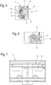
- the liner 11 has a first chamber 37 in which the first rod 14 is partly inserted and a second chamber 38 in which the second rod 15 is partly inserted, as illustrated in Figure 4 .
- Each between the first rod 14 and the second rod 15 is movable in the respective first chamber 37 and second chamber 38 from a retracted position to an extended position, and vice versa.
- the movement of the first rod 14 from the retracted position to the extended position allows a translation of the supporting structure 2 in a first direction, for example towards the right of the driver.
- the movement of the second rod 15 from the retracted position to the extended position allows a translation of the supporting structure 2 in a second direction, opposite the first direction, for example towards the left of the driver.
- the actuation of the first rod 14 or of the second rod 15 is performed by means of a hydraulic system not illustrated.
- the positioning device 1 comprises a unit 16 for supporting the supporting structure 2 slidably constrained to it.
- the supporting structure 2 is movable relative to the supporting unit 16.
- the liner 11 is connected to the supporting unit 16 at two coupling zones, the coupling zones being preferably positioned symmetrical to each other.
- the supporting unit 16 comprises a first bar 27 and a second bar 28 positioned parallel to each other along a vertical direction and a third bar 29, joining the first bar 27 and the second bar 28, positioned along a horizontal direction.
- the first bar 27 and the second bar 28 comprise respective rolling elements 30 designed to slide in respective guides of an upright 36 of the lift truck, see Figure 1 .
- the third bar 29 comprises a plurality of rolling elements 31 designed to slide in a seat 32 made in the upper bar 4 of the supporting structure 2.
- the translation-positioning device comprises anti-friction elements 22 interposed between them.
- anti-friction elements 22 are interposed between the liner 11 of the movement unit 9 and the lower bar 5 of the supporting structure 2.
- anti-friction elements 22 are interposed between the first side surface 34 of the liner 11 and the lower bar 5 of the supporting structure 2, as shown in Figure 5 .
- the antifriction elements 22 are preferably in the form of bronze runners.
- the positioning device 1 comprises first means 17 for coupling the supporting structure 2 and the movement unit 9 configured to prevent a relative rotation of the supporting structure 2 with respect to the supporting unit 16.
- the relative rotation is understood as rotation about a horizontal axis parallel to the longitudinal direction of extension of the upper bar 4 and of the lower bar 5 of the supporting structure 2.
- the first coupling means 17 comprise a male element 19, positioned on the liner 11 of the movement unit 9, and a female element 20, shaped to match the male element 19, connected to the lower bar 5 of the supporting structure 2, as illustrated in Figure 6 .
- the male element 19 has a polygonal cross-section, in particular a right-angled trapezium cross-section.
- the positioning device 1 comprises second coupling means 18 configured to prevent a relative translation of the supporting structure 2 relative to the supporting unit 16 along a vertical direction.
- the second coupling means 18 comprise a plurality of plate-shaped elements 21 interposed between the liner 11 of the movement unit 9 and the lower bar 5.
- the plate-shaped elements 21 are interposed between the bottom surface 33 of the liner 11 and the lower bar 5, as shown in Figure 5 .
- the plate-shaped elements 21 are connected to the lower bar 5 by fixing means.
- the positioning device 1 comprises a first actuator unit 25 and a second actuator unit 26 each configured to move a respective fork 5.
- This movement allows the forks 3 to be positioned relative to each other.
- the movement is a relative translation along the horizontal direction D parallel to the longitudinal direction of extension of the upper bar 4 and of the lower bar 5 of the supporting structure 2.
Landscapes
- Engineering & Computer Science (AREA)
- Transportation (AREA)
- Structural Engineering (AREA)
- Civil Engineering (AREA)
- Life Sciences & Earth Sciences (AREA)
- Geology (AREA)
- Mechanical Engineering (AREA)
- Forklifts And Lifting Vehicles (AREA)
Claims (12)
- Positioniervorrichtung zum Positionieren von Gabeln für einen Gabelstapler, umfassend:eine Tragestruktur (2), die ausgelegt ist, um ein Paar Gabeln (3) zu halten, die mindestens eine obere Stange (4) und eine untere Stange (5) umfasst, die eine Hauptlängsausdehnung aufweisen, und eine erste Seitenstange (6) und eine zweite Seitenstange (7), die die untere Stange (4) und die obere Stange (5) verbinden, wobei die Tragestruktur (2) ein Sichtfenster (8) aufweist, das zumindest durch die obere Stange (4), durch die untere Stange (5) und durch die erste Seitenstange (6) sowie durch die zweite Seitenstange (7) definiert ist;eine Bewegungseinheit (9) zum Bewegen der Tragestruktur (2), die ausgelegt ist, um die Tragestruktur (2) entlang einer horizontalen Richtung (D) parallel zur Längsausdehnungsrichtung der oberen Stange (4) und der unteren Stange (5) der Tragestruktur (2) zu verschieben, wodurch die Bewegungseinheit (9) an der unteren Stange (5) der Tragestruktur (2) außerhalb des Sichtfensters (8) positioniert wird, dadurch gekennzeichnet, dass die untere Stange (5) einen Sitz (10) zur Aufnahme von mindestens einem Teil der Bewegungseinheit (9) umfasst.
- Vorrichtung nach Anspruch 1, dadurch gekennzeichnet, dass die Bewegungseinheit (10) eine Buchse (11) umfasst, die zumindest teilweise in den Sitz (10) zur Aufnahme der unteren Stange (5) eingefügt ist.
- Vorrichtung nach Anspruch 2, dadurch gekennzeichnet, dass die Buchse (11) mindestens eine flache oberseitige Oberfläche (12) umfasst, die zum Verschieben von Wälzkörpern (13) ausgelegt ist, die mit der unteren Stange (5) verbunden sind.
- Vorrichtung nach Anspruch 2 oder 3, dadurch gekennzeichnet, dass die Buchse (11) einen vieleckigen, insbesondere quadratischen Querschnitt aufweist.
- Vorrichtung nach einem der Ansprüche 2 bis 4, dadurch gekennzeichnet, dass die Bewegungseinheit (9) einen ersten Stab (14) umfasst, der mit der ersten Seitenstange (6) verbunden ist, und einen zweiten Stab (15), der mit der zweiten Seitenstange (7) verbunden ist, positioniert auf entgegengesetzten Seiten der Buchse (11), wobei die Buchse (11) eine erste Kammer (37) aufweist, in der der erste Stab (14) bewegbar ist, und eine zweite Kammer (38), in der der zweite Stab (15) bewegbar ist.
- Vorrichtung nach einem der Ansprüche 2 bis 5, dadurch gekennzeichnet, dass sie eine Einheit (16) zum Tragen der Tragestruktur (2) umfasst, die verschiebbar damit verbunden ist, wobei die Buchse (11) der Bewegungseinheit (9) mit mindestens einem Teil der Trageeinheit (16) verbunden ist.
- Vorrichtung nach Anspruch 6, dadurch gekennzeichnet, dass sie erste Mittel (17) zum Kuppeln der Tragestruktur (2) und der Bewegungseinheit (9) umfasst, die ausgelegt sind, um eine relative Drehung der Tragestruktur (2) relativ zur Trageeinheit (16) um eine horizontale Richtung (D) zu vermeiden, die parallel zur Längsausdehnungsrichtung der oberen Stange (4) und der unteren Stange (5) der Tragestruktur (2) verläuft.
- Vorrichtung nach Anspruch 7, dadurch gekennzeichnet, dass die ersten Kupplungsmittel (17) ein Federelement (19) umfassen, das in der Buchse (11) der Bewegungseinheit (9) positioniert ist, und ein Nutelement (20), das mit der unteren Stange (5) der Tragestruktur (16) verbunden ist.
- Vorrichtung nach einem der Ansprüche 6 bis 8, dadurch gekennzeichnet, dass sie zweite Mittel (18) zum Kuppeln der Tragestruktur (2) und der Bewegungseinheit (9) umfasst, die ausgelegt sind, um eine relative Verschiebung der Tragestruktur (2) in Bezug auf die Trageeinheit (16) entlang einer vertikalen Richtung zu vermeiden.
- Vorrichtung nach Anspruch 9, dadurch gekennzeichnet, dass die zweiten Kupplungsmittel (18) eine Vielzahl von plattenförmigen Elementen (21) umfassen, die zwischen der Buchse (11) der Bewegungseinheit (9) und der unteren Stange (5) eingesetzt sind.
- Vorrichtung nach einem der vorhergehenden Ansprüche, dadurch gekennzeichnet, dass sie mindestens eine Betätigungseinheit (23) und Antriebsmittel (24) der Betätigungseinheit (23) umfasst, um die Gabeln (3) relativ zueinander entlang einer horizontalen Richtung (D) parallel zur Längsausdehnungsrichtung der oberen Stange (4) und der unteren Stange (5) der Tragestruktur (2) zu bewegen.
- Vorrichtung nach einem der Ansprüche 1 bis 10, dadurch gekennzeichnet, dass sie eine erste Betätigungseinheit (25) und eine zweite Betätigungseinheit (26) umfasst, die jeweils ausgelegt sind, um eine jeweilige Gabel (3) entlang einer horizontalen Richtung (D) parallel zur Längsausdehnungsrichtung der oberen Stange (4) und der unteren Stange (5) der Tragestruktur (2) zu bewegen.
Applications Claiming Priority (1)
| Application Number | Priority Date | Filing Date | Title |
|---|---|---|---|
| IT102021000032576A IT202100032576A1 (it) | 2021-12-23 | 2021-12-23 | Dispositivo posizionatore di forche per carrello elevatore |
Publications (2)
| Publication Number | Publication Date |
|---|---|
| EP4201870A1 EP4201870A1 (de) | 2023-06-28 |
| EP4201870B1 true EP4201870B1 (de) | 2025-05-07 |
Family
ID=80625224
Family Applications (1)
| Application Number | Title | Priority Date | Filing Date |
|---|---|---|---|
| EP22215384.3A Active EP4201870B1 (de) | 2021-12-23 | 2022-12-21 | Ein positioniervorrichtung zum positionieren von gabeln für einen gabelstapler |
Country Status (3)
| Country | Link |
|---|---|
| EP (1) | EP4201870B1 (de) |
| ES (1) | ES3038724T3 (de) |
| IT (1) | IT202100032576A1 (de) |
Family Cites Families (3)
| Publication number | Priority date | Publication date | Assignee | Title |
|---|---|---|---|---|
| JPH01174396U (de) * | 1988-05-31 | 1989-12-12 | ||
| US5707201A (en) * | 1992-06-11 | 1998-01-13 | Rightline Equipment, Inc. | Forklift truck side shifter |
| ITMI20040325A1 (it) * | 2004-02-25 | 2004-05-25 | Bolzoni Spa | Gruppo modulare per realizzare strutture di supporto e traslazione motorizzata di forche per carrelli elevatori |
-
2021
- 2021-12-23 IT IT102021000032576A patent/IT202100032576A1/it unknown
-
2022
- 2022-12-21 EP EP22215384.3A patent/EP4201870B1/de active Active
- 2022-12-21 ES ES22215384T patent/ES3038724T3/es active Active
Also Published As
| Publication number | Publication date |
|---|---|
| IT202100032576A1 (it) | 2023-06-23 |
| ES3038724T3 (en) | 2025-10-15 |
| EP4201870A1 (de) | 2023-06-28 |
Similar Documents
| Publication | Publication Date | Title |
|---|---|---|
| AU2015263164B2 (en) | Forklift arrangement | |
| NL2004999C2 (en) | Load-handling apparatus adapted to be mounted on an elevatable lift carriage of a lift truck as well as a lift truck comprising such a load-handling apparatus. | |
| EP3034453B1 (de) | Vorrichtung mit seitenschieber | |
| CA2992017C (en) | Method and apparatus for transporting and steering a heavy load | |
| US7632055B2 (en) | Fork-lift attachment with multiple forks | |
| US20140219760A1 (en) | Reach assembly with offset pivot points for a materials handling vehicle | |
| JP5055128B2 (ja) | フォークポジショナー | |
| NL1032038C2 (nl) | Hefbrug en lift daarin. | |
| EP4201870B1 (de) | Ein positioniervorrichtung zum positionieren von gabeln für einen gabelstapler | |
| US9221658B2 (en) | Device for picking up loads | |
| US6202774B1 (en) | Transport module for the moving of heavy loads | |
| KR20180031404A (ko) | 주차설비용 차량운반장치 | |
| CN109382804B (zh) | 升降自如的工件支撑装置 | |
| RU2004119990A (ru) | Грузоподъемное устройство для поддержки груза на транспортном средстве (варианты) | |
| KR101510681B1 (ko) | 시저스 리프트 | |
| GB2266700A (en) | Load lifting carriage for an industrial lift truck | |
| US20060182575A1 (en) | Pull and lift system for transporting roofing materials | |
| EP3560793B1 (de) | Materialhandhabungsfahrzeug | |
| EP2977248A1 (de) | Abdecksystem für container | |
| US20230389692A1 (en) | Segmented support body | |
| JP6016568B2 (ja) | 門形工作機械 | |
| EP0949192A2 (de) | Mittel zum Verstellen von der horizontalen Basisachse von Vorrichtungen für Gabelhubwagen oder ähnlichem | |
| KR101878662B1 (ko) | 주차설비용 차량운반장치 | |
| KR101882144B1 (ko) | 리프팅 장치 | |
| CN220951045U (zh) | 一种同步顶升机构 |
Legal Events
| Date | Code | Title | Description |
|---|---|---|---|
| PUAI | Public reference made under article 153(3) epc to a published international application that has entered the european phase |
Free format text: ORIGINAL CODE: 0009012 |
|
| STAA | Information on the status of an ep patent application or granted ep patent |
Free format text: STATUS: THE APPLICATION HAS BEEN PUBLISHED |
|
| AK | Designated contracting states |
Kind code of ref document: A1 Designated state(s): AL AT BE BG CH CY CZ DE DK EE ES FI FR GB GR HR HU IE IS IT LI LT LU LV MC ME MK MT NL NO PL PT RO RS SE SI SK SM TR |
|
| STAA | Information on the status of an ep patent application or granted ep patent |
Free format text: STATUS: REQUEST FOR EXAMINATION WAS MADE |
|
| 17P | Request for examination filed |
Effective date: 20231219 |
|
| RBV | Designated contracting states (corrected) |
Designated state(s): AL AT BE BG CH CY CZ DE DK EE ES FI FR GB GR HR HU IE IS IT LI LT LU LV MC ME MK MT NL NO PL PT RO RS SE SI SK SM TR |
|
| GRAP | Despatch of communication of intention to grant a patent |
Free format text: ORIGINAL CODE: EPIDOSNIGR1 |
|
| STAA | Information on the status of an ep patent application or granted ep patent |
Free format text: STATUS: GRANT OF PATENT IS INTENDED |
|
| RIC1 | Information provided on ipc code assigned before grant |
Ipc: B66F 9/14 20060101AFI20241104BHEP |
|
| INTG | Intention to grant announced |
Effective date: 20241203 |
|
| GRAS | Grant fee paid |
Free format text: ORIGINAL CODE: EPIDOSNIGR3 |
|
| GRAA | (expected) grant |
Free format text: ORIGINAL CODE: 0009210 |
|
| STAA | Information on the status of an ep patent application or granted ep patent |
Free format text: STATUS: THE PATENT HAS BEEN GRANTED |
|
| AK | Designated contracting states |
Kind code of ref document: B1 Designated state(s): AL AT BE BG CH CY CZ DE DK EE ES FI FR GB GR HR HU IE IS IT LI LT LU LV MC ME MK MT NL NO PL PT RO RS SE SI SK SM TR |
|
| REG | Reference to a national code |
Ref country code: GB Ref legal event code: FG4D |
|
| REG | Reference to a national code |
Ref country code: CH Ref legal event code: EP |
|
| REG | Reference to a national code |
Ref country code: DE Ref legal event code: R096 Ref document number: 602022014215 Country of ref document: DE |
|
| REG | Reference to a national code |
Ref country code: IE Ref legal event code: FG4D |
|
| P01 | Opt-out of the competence of the unified patent court (upc) registered |
Free format text: CASE NUMBER: APP_24468/2025 Effective date: 20250522 |
|
| REG | Reference to a national code |
Ref country code: SE Ref legal event code: TRGR |
|
| REG | Reference to a national code |
Ref country code: NL Ref legal event code: FP |
|
| PG25 | Lapsed in a contracting state [announced via postgrant information from national office to epo] |
Ref country code: PT Free format text: LAPSE BECAUSE OF FAILURE TO SUBMIT A TRANSLATION OF THE DESCRIPTION OR TO PAY THE FEE WITHIN THE PRESCRIBED TIME-LIMIT Effective date: 20250908 Ref country code: FI Free format text: LAPSE BECAUSE OF FAILURE TO SUBMIT A TRANSLATION OF THE DESCRIPTION OR TO PAY THE FEE WITHIN THE PRESCRIBED TIME-LIMIT Effective date: 20250507 |
|
| REG | Reference to a national code |
Ref country code: LT Ref legal event code: MG9D |
|
| PG25 | Lapsed in a contracting state [announced via postgrant information from national office to epo] |
Ref country code: GR Free format text: LAPSE BECAUSE OF FAILURE TO SUBMIT A TRANSLATION OF THE DESCRIPTION OR TO PAY THE FEE WITHIN THE PRESCRIBED TIME-LIMIT Effective date: 20250808 |
|
| PG25 | Lapsed in a contracting state [announced via postgrant information from national office to epo] |
Ref country code: PL Free format text: LAPSE BECAUSE OF FAILURE TO SUBMIT A TRANSLATION OF THE DESCRIPTION OR TO PAY THE FEE WITHIN THE PRESCRIBED TIME-LIMIT Effective date: 20250507 |
|
| REG | Reference to a national code |
Ref country code: ES Ref legal event code: FG2A Ref document number: 3038724 Country of ref document: ES Kind code of ref document: T3 Effective date: 20251015 Ref country code: AT Ref legal event code: MK05 Ref document number: 1792333 Country of ref document: AT Kind code of ref document: T Effective date: 20250507 |
|
| PG25 | Lapsed in a contracting state [announced via postgrant information from national office to epo] |
Ref country code: BG Free format text: LAPSE BECAUSE OF FAILURE TO SUBMIT A TRANSLATION OF THE DESCRIPTION OR TO PAY THE FEE WITHIN THE PRESCRIBED TIME-LIMIT Effective date: 20250507 |
|
| PG25 | Lapsed in a contracting state [announced via postgrant information from national office to epo] |
Ref country code: HR Free format text: LAPSE BECAUSE OF FAILURE TO SUBMIT A TRANSLATION OF THE DESCRIPTION OR TO PAY THE FEE WITHIN THE PRESCRIBED TIME-LIMIT Effective date: 20250507 |
|
| PG25 | Lapsed in a contracting state [announced via postgrant information from national office to epo] |
Ref country code: AT Free format text: LAPSE BECAUSE OF FAILURE TO SUBMIT A TRANSLATION OF THE DESCRIPTION OR TO PAY THE FEE WITHIN THE PRESCRIBED TIME-LIMIT Effective date: 20250507 |
|
| PG25 | Lapsed in a contracting state [announced via postgrant information from national office to epo] |
Ref country code: RS Free format text: LAPSE BECAUSE OF FAILURE TO SUBMIT A TRANSLATION OF THE DESCRIPTION OR TO PAY THE FEE WITHIN THE PRESCRIBED TIME-LIMIT Effective date: 20250807 |
|
| PG25 | Lapsed in a contracting state [announced via postgrant information from national office to epo] |
Ref country code: IS Free format text: LAPSE BECAUSE OF FAILURE TO SUBMIT A TRANSLATION OF THE DESCRIPTION OR TO PAY THE FEE WITHIN THE PRESCRIBED TIME-LIMIT Effective date: 20250907 |
|
| PG25 | Lapsed in a contracting state [announced via postgrant information from national office to epo] |
Ref country code: LV Free format text: LAPSE BECAUSE OF FAILURE TO SUBMIT A TRANSLATION OF THE DESCRIPTION OR TO PAY THE FEE WITHIN THE PRESCRIBED TIME-LIMIT Effective date: 20250507 |
|
| PGFP | Annual fee paid to national office [announced via postgrant information from national office to epo] |
Ref country code: NO Payment date: 20251218 Year of fee payment: 4 |
|
| PG25 | Lapsed in a contracting state [announced via postgrant information from national office to epo] |
Ref country code: DK Free format text: LAPSE BECAUSE OF FAILURE TO SUBMIT A TRANSLATION OF THE DESCRIPTION OR TO PAY THE FEE WITHIN THE PRESCRIBED TIME-LIMIT Effective date: 20250507 Ref country code: SM Free format text: LAPSE BECAUSE OF FAILURE TO SUBMIT A TRANSLATION OF THE DESCRIPTION OR TO PAY THE FEE WITHIN THE PRESCRIBED TIME-LIMIT Effective date: 20250507 |
|
| PGFP | Annual fee paid to national office [announced via postgrant information from national office to epo] |
Ref country code: FR Payment date: 20251223 Year of fee payment: 4 Ref country code: NL Payment date: 20251222 Year of fee payment: 4 |
|
| PGFP | Annual fee paid to national office [announced via postgrant information from national office to epo] |
Ref country code: SE Payment date: 20251222 Year of fee payment: 4 |
|
| PG25 | Lapsed in a contracting state [announced via postgrant information from national office to epo] |
Ref country code: CZ Free format text: LAPSE BECAUSE OF FAILURE TO SUBMIT A TRANSLATION OF THE DESCRIPTION OR TO PAY THE FEE WITHIN THE PRESCRIBED TIME-LIMIT Effective date: 20250507 |
|
| PG25 | Lapsed in a contracting state [announced via postgrant information from national office to epo] |
Ref country code: EE Free format text: LAPSE BECAUSE OF FAILURE TO SUBMIT A TRANSLATION OF THE DESCRIPTION OR TO PAY THE FEE WITHIN THE PRESCRIBED TIME-LIMIT Effective date: 20250507 |
|
| PG25 | Lapsed in a contracting state [announced via postgrant information from national office to epo] |
Ref country code: SK Free format text: LAPSE BECAUSE OF FAILURE TO SUBMIT A TRANSLATION OF THE DESCRIPTION OR TO PAY THE FEE WITHIN THE PRESCRIBED TIME-LIMIT Effective date: 20250507 |
|
| REG | Reference to a national code |
Ref country code: DE Ref legal event code: R097 Ref document number: 602022014215 Country of ref document: DE |
|
| PG25 | Lapsed in a contracting state [announced via postgrant information from national office to epo] |
Ref country code: RO Free format text: LAPSE BECAUSE OF FAILURE TO SUBMIT A TRANSLATION OF THE DESCRIPTION OR TO PAY THE FEE WITHIN THE PRESCRIBED TIME-LIMIT Effective date: 20250507 |
|
| PLBE | No opposition filed within time limit |
Free format text: ORIGINAL CODE: 0009261 |
|
| STAA | Information on the status of an ep patent application or granted ep patent |
Free format text: STATUS: NO OPPOSITION FILED WITHIN TIME LIMIT |
|
| REG | Reference to a national code |
Ref country code: CH Ref legal event code: L10 Free format text: ST27 STATUS EVENT CODE: U-0-0-L10-L00 (AS PROVIDED BY THE NATIONAL OFFICE) Effective date: 20260318 |
|
| PGFP | Annual fee paid to national office [announced via postgrant information from national office to epo] |
Ref country code: ES Payment date: 20260122 Year of fee payment: 4 |
|
| PGFP | Annual fee paid to national office [announced via postgrant information from national office to epo] |
Ref country code: DE Payment date: 20251229 Year of fee payment: 4 |
|
| 26N | No opposition filed |
Effective date: 20260210 |
|
| PGFP | Annual fee paid to national office [announced via postgrant information from national office to epo] |
Ref country code: BE Payment date: 20260109 Year of fee payment: 4 Ref country code: IT Payment date: 20251231 Year of fee payment: 4 |