EP4201876A2 - Vorrichtung zur herstellung von wasserstoffgas mittels photokatalysator - Google Patents
Vorrichtung zur herstellung von wasserstoffgas mittels photokatalysator Download PDFInfo
- Publication number
- EP4201876A2 EP4201876A2 EP22215604.4A EP22215604A EP4201876A2 EP 4201876 A2 EP4201876 A2 EP 4201876A2 EP 22215604 A EP22215604 A EP 22215604A EP 4201876 A2 EP4201876 A2 EP 4201876A2
- Authority
- EP
- European Patent Office
- Prior art keywords
- light
- light source
- water
- photocatalyst
- hydrogen gas
- Prior art date
- Legal status (The legal status is an assumption and is not a legal conclusion. Google has not performed a legal analysis and makes no representation as to the accuracy of the status listed.)
- Granted
Links
Images


Classifications
-
- C—CHEMISTRY; METALLURGY
- C01—INORGANIC CHEMISTRY
- C01B—NON-METALLIC ELEMENTS; COMPOUNDS THEREOF; METALLOIDS OR COMPOUNDS THEREOF NOT COVERED BY SUBCLASS C01C
- C01B3/00—Hydrogen; Gaseous mixtures containing hydrogen; Separation of hydrogen from mixtures containing it; Purification of hydrogen; Reversible storage of hydrogen
- C01B3/02—Production of hydrogen; Production of gaseous mixtures containing hydrogen
- C01B3/04—Production of hydrogen; Production of gaseous mixtures containing hydrogen by decomposition of inorganic compounds
- C01B3/042—Decomposition of water
-
- B—PERFORMING OPERATIONS; TRANSPORTING
- B01—PHYSICAL OR CHEMICAL PROCESSES OR APPARATUS IN GENERAL
- B01J—CHEMICAL OR PHYSICAL PROCESSES, e.g. CATALYSIS OR COLLOID CHEMISTRY; THEIR RELEVANT APPARATUS
- B01J19/00—Chemical, physical or physico-chemical processes in general; Their relevant apparatus
- B01J19/08—Processes employing the direct application of electric or wave energy, or particle radiation; Apparatus therefor
- B01J19/12—Processes employing the direct application of electric or wave energy, or particle radiation; Apparatus therefor employing electromagnetic waves
- B01J19/122—Incoherent waves
- B01J19/127—Sunlight; Visible light
-
- B—PERFORMING OPERATIONS; TRANSPORTING
- B01—PHYSICAL OR CHEMICAL PROCESSES OR APPARATUS IN GENERAL
- B01J—CHEMICAL OR PHYSICAL PROCESSES, e.g. CATALYSIS OR COLLOID CHEMISTRY; THEIR RELEVANT APPARATUS
- B01J2219/00—Chemical, physical or physico-chemical processes in general; Their relevant apparatus
- B01J2219/08—Processes employing the direct application of electric or wave energy, or particle radiation; Apparatus therefor
- B01J2219/0873—Materials to be treated
- B01J2219/0892—Materials to be treated involving catalytically active material
-
- B—PERFORMING OPERATIONS; TRANSPORTING
- B01—PHYSICAL OR CHEMICAL PROCESSES OR APPARATUS IN GENERAL
- B01J—CHEMICAL OR PHYSICAL PROCESSES, e.g. CATALYSIS OR COLLOID CHEMISTRY; THEIR RELEVANT APPARATUS
- B01J35/00—Catalysts, in general, characterised by their form or physical properties
- B01J35/30—Catalysts, in general, characterised by their form or physical properties characterised by their physical properties
- B01J35/39—Photocatalytic properties
-
- C—CHEMISTRY; METALLURGY
- C01—INORGANIC CHEMISTRY
- C01B—NON-METALLIC ELEMENTS; COMPOUNDS THEREOF; METALLOIDS OR COMPOUNDS THEREOF NOT COVERED BY SUBCLASS C01C
- C01B2203/00—Integrated processes for the production of hydrogen or synthesis gas
- C01B2203/02—Processes for making hydrogen or synthesis gas
- C01B2203/0266—Processes for making hydrogen or synthesis gas containing a decomposition step
- C01B2203/0277—Processes for making hydrogen or synthesis gas containing a decomposition step containing a catalytic decomposition step
-
- C—CHEMISTRY; METALLURGY
- C01—INORGANIC CHEMISTRY
- C01B—NON-METALLIC ELEMENTS; COMPOUNDS THEREOF; METALLOIDS OR COMPOUNDS THEREOF NOT COVERED BY SUBCLASS C01C
- C01B2203/00—Integrated processes for the production of hydrogen or synthesis gas
- C01B2203/10—Catalysts for performing the hydrogen forming reactions
- C01B2203/1005—Arrangement or shape of catalyst
- C01B2203/1035—Catalyst coated on equipment surfaces, e.g. reactor walls
-
- C—CHEMISTRY; METALLURGY
- C01—INORGANIC CHEMISTRY
- C01B—NON-METALLIC ELEMENTS; COMPOUNDS THEREOF; METALLOIDS OR COMPOUNDS THEREOF NOT COVERED BY SUBCLASS C01C
- C01B2203/00—Integrated processes for the production of hydrogen or synthesis gas
- C01B2203/10—Catalysts for performing the hydrogen forming reactions
- C01B2203/1041—Composition of the catalyst
-
- Y—GENERAL TAGGING OF NEW TECHNOLOGICAL DEVELOPMENTS; GENERAL TAGGING OF CROSS-SECTIONAL TECHNOLOGIES SPANNING OVER SEVERAL SECTIONS OF THE IPC; TECHNICAL SUBJECTS COVERED BY FORMER USPC CROSS-REFERENCE ART COLLECTIONS [XRACs] AND DIGESTS
- Y02—TECHNOLOGIES OR APPLICATIONS FOR MITIGATION OR ADAPTATION AGAINST CLIMATE CHANGE
- Y02E—REDUCTION OF GREENHOUSE GAS [GHG] EMISSIONS, RELATED TO ENERGY GENERATION, TRANSMISSION OR DISTRIBUTION
- Y02E60/00—Enabling technologies; Technologies with a potential or indirect contribution to GHG emissions mitigation
- Y02E60/30—Hydrogen technology
- Y02E60/36—Hydrogen production from non-carbon containing sources, e.g. by water electrolysis
Definitions
- the present invention relates to a hydrogen gas producing apparatus, and more specifically to an apparatus which manufactures hydrogen gas by the decomposition reaction of water using a photocatalyst.
- Hydrogen gas is expected to be used as clean, next-generation fuel generating no carbon dioxide in its combustion. Since hydrogen gas can be produced by a decomposition reaction of water induced by a photocatalyst with light energy, various techniques for the production of hydrogen gas using a photocatalyst have been proposed. For instance, in patent documents 1 and 2, there are disclosed photocatalysts inducing a decomposition reaction of water by irradiation of ultraviolet light or visible light to generate hydrogen gas and their preparing methods. Patent document 3 discloses a structure of a hydrogen production apparatus including a water oxidation reaction means using a photocatalyst with ultraviolet to visible light in the sunlight and a water reduction reaction means using heat of visible to infrared light in the sunlight.
- Patent document 4 has proposed a structure of a hydrogen generation device in which water with dispersed photocatalyst particles is circulated in a housing having a light-receiving window so that a water decomposition reaction to generate hydrogen gas will be caused by light.
- Patent document 5 has proposed a structure of a hydrogen generation system in which a receiver, having an electrode consisting of a photocatalyst placed in water, is irradiated with light accumulated by means of a sunlight condenser so that valence electrons in the photocatalyst will be excited to cause electrolysis of its surrounding water and produce hydrogen gas continuously.
- Non-patent document 1 "Photocatalytic water splitting with a quantum efficiency of almost unity" Tsuyoshi Takata, Junzhe Jiang, Yoshihisa Sakata, Mamiko Nakabayashi, Naoya Shibata, Vikas Nandal, Kazuhiko Seki, Takashi Hisatomi & Kazunari Domen, Nature volume 581, pages411-414 (2020 )
- the production efficiency of hydrogen gas becomes higher as the temperature of water, which is a reactant, becomes higher.
- the warming of water is effective for raising the efficiency of the production of hydrogen gas, and in that case, if the waste heat of a light source which generates light irradiated to a photocatalyst can be used without using any separate heater to which energy is supplied from the outside, more concretely, if a structure in which, as well as the radiant heat from the light source to the water, the waste heat of the light source can be transferred directly to the water is employed, it will also become possible to improve more the utilization efficiency of energy in connection with the hydrogen gas production.
- deterioration of a surface of the housing is suppressed while the reduction of its heat transfer efficiency is also suppressed as low as possible, and in that case, a structure that improves the light reaction amount of water is advantageous.
- one of the objects of the present invention is to provide an apparatus of producing hydrogen gas by the decomposition reaction of water using a photocatalyst, which apparatus has a structure in which water is warmed by waste heat of a light source for improving the efficiency of the hydrogen gas production.
- another object of the present embodiment is to provide such an apparatus having a structure in which a light source, together with a housing carrying it, is sunk in water, wherein degradation of the surface of the housing can be suppressed and simultaneously the light reaction amount of the water can also be increased.
- a hydrogen gas producing apparatus comprising:
- the "photocatalyst material” may be a material which can cause the decomposition reaction of water to reduce water and generate hydrogen gas when it is irradiated with light as noted above.
- the "photocatalyst body” is composed of the photocatalyst material, which may be particles dispersed in the water, a member made of the photocatalyst material itself, or an arbitrary substrate fixed with the photocatalyst material thereon, placed at an arbitrary position in the water, or both of them (Hereinafter, in this specification, when “a photocatalyst” is referred to simply, a photocatalyst material is indicated.).
- the "light source” may be an arbitrary form of emitting light, which is absorbed by the photocatalyst material and causes the decomposition reaction of water, typically by receiving the supply of electric power, and the light source is carried by the housing and placed in the water while being waterproofed together with the housing.
- the housing is to be formed of a material with high thermal conductivity, and typically, the housing may be formed of a metal material, such as aluminum.
- the emission wavelength of the light source is chosen so that the light irradiated to the photocatalyst will be efficiently absorbed into the photocatalyst to generate excited electrons and electron holes, and preferably so as to fall in a wavelength band in which the quantum yield of the photocatalyst exceeds a predetermined threshold value (chosen arbitrarily).
- a predetermined threshold value chosen arbitrarily.
- the quantum yield of a typical photocatalyst rapidly increases when the wavelength of the irradiated light is below the vicinity of a certain wavelength.
- the light source may be chosen so that the emission wavelength of the light source will be in the shorter side than the wavelength at which the rapid increase of the quantum yield of the photocatalyst occurs.
- photocatalyst which can be used in the present invention, for instance, SrTiOs (strontium titanate), La 2 Ti 2 O 7 (lanthanum titanate), Ga 2 O 3 (gallium oxide), GaN (gallium nitride), NaTaOs (sodium tantalate), TiO 2 (titanium oxide), etc. are usable.
- these photocatalysts may be used while a co-catalyst is added appropriately.
- LED light emission diodes
- InGaN indium gallium nitride
- diamond ultraviolet
- gallium nitride GaN
- AlGaN aluminum gallium nitride
- blue zinc selenide
- blue zinc oxide
- zinc oxide near-ultraviolet, purple, blue
- the surface of the housing in contact with the water is coated with a photocatalyst material.
- the photocatalyst material coated on the housing surface may be a material identical to, or different material from, that of the photocatalyst body.
- the structure of the above-mentioned apparatus of the present invention in which the decomposition reaction of water is caused by irradiating with the light the photocatalyst body in contact with water to produce hydrogen gas, there is provided the structure of warming water by the waste heat of the light source by sinking in the water the light source carried by the housing. According to this structure, the efficiency of hydrogen gas production will be improved because the water, which is a reactant, is warmed. Further, since the warming of the water is achieved using the waste heat of the light source, no heater for warming water, etc. is needed to be prepared separately, and therefore, since it is not necessary to supply energy for warming water separately, the increase in efficiency of the energy used in the hydrogen gas production will be attained.
- the surface of the housing sunk in the water is coated with a photocatalyst material, and thereby, when the housing is made of the metal material, etc., the metal of the housing surface is prevented from being in contact with water directly, so that the dissolution of the metal on the housing surface will be prevented and thereby the deterioration of the housing surface will be suppressed.
- the light emitted from the light source in the water propagates in various directions in the water because of scattering in various ways (Rayleigh scattering, Raman scattering, etc.) and reflection on inner walls of the container portion and the water surface.
- the scattered or reflected light strikes upon the photocatalyst of the housing surface of the light source, the light is absorbed therein, causing the decomposition reaction of water on the housing surface, and thereby the further improvement in the efficiency of hydrogen gas production is expected. Furthermore, according to the above-mentioned structure, since the light source is placed in the container portion and the configuration of the outside of the container portion is simplified, the space required for the placing of the apparatus can be made compact, and thus, it becomes easy to increase the size of the container portion, scaling up the apparatus.
- the apparatus of the present invention there may be provided a structure in which the light emitted from the light source is irradiated also to the photocatalyst material coated on the housing surface in an arbitrary manner.
- the apparatus of the present invention may be designed such that two or more light sources and housings carrying these light sources are placed in the water in the container portion and the light being emitted from one of the light sources is irradiated to the photocatalyst material coated on the surface of the housing of another of the light sources also.
- the apparatus of the present invention may be designed such that the light emitted from the light source is confined in the container portion, and for this, for instance, the container portion may have a light reflecting mechanism for confining the light emitted from the light source in the container portion by providing a light reflecting board on the inner side of the container portion.
- the production efficiency of hydrogen gas decreases as the density of the light irradiated to the photocatalyst is increased. This is considered because, even when the densities of excited electrons and electron holes generated in the photocatalyst are increased by the increase of the light intensity, the speed of the decomposition reaction of water with the excited electrons and electron holes is slow, and thus, the excited electrons and electron holes will disappear due to their recombination before those react to water, respectively, and accordingly, the energy of the light is not effectively used for the production of hydrogen gas.
- the density of the light emitted from the light source is adjusted to be an appropriate value while being balanced with the decrease in the production efficiency of hydrogen gas.
- the density of the light irradiated to the photocatalyst body may be adjusted at, or lower than, the density at which a photocatalyst efficiency (a ratio of the generated amount of hydrogen gas per the amount of photons incident on the photocatalyst material) becomes more than a predetermined value.
- the density of light irradiated to a photocatalyst body is made at or lower than 0.1 W/cm 2 , it is preferable that the relation between the output P of a light source and the irradiated area A is to be adjusted so that the output of the light source P / the irradiated area A ⁇ 0.1 W/cm 2 will be established.
- the light source may be configured to operate with electric power obtained by solar power generation and emit the light to be irradiated to the photocatalyst body and the waste heat in the operation of the light source may be transmitted to water from the housing.
- the production of hydrogen gas will be achieved by renewable energy.
- the light source instead of irradiating the photocatalyst body with the sunlight itself, it becomes possible to supply the light energy to the photocatalyst body while condensing the solar energy which is thin per unit area, attaining the miniaturization of the apparatus.
- the rated output of the light source may be adjusted so that the light-emitting efficiency of the light source will be maximized when the current at the rated current value of the solar power generation is supplied to the light source.
- the solar energy can be more efficiently used for the production of hydrogen gas.
- the solar power generation its output is changed depending upon the sunshine condition, and thus, the available current can change moment by moment.
- the efficiency of the energy used in the production of hydrogen gas will be improved when the light source is operated moment by moment so that its light-emitting efficiency will be maximized.
- two or more LEDs may be employed as the light source, and in that case, since the light-emitting efficiency of each LED changes depending upon the current inputted into it, the light source may be designed so that the number of the actually operating LEDs in the two or more LEDs will be changed according to the output current of the solar power generation so as to maximize the light-emitting efficiency of the light source. Thereby, it is expected that solar energy is more effectively converted into the light from the light source to be used for the production of hydrogen gas.
- the light source in the production of hydrogen gas through the decomposition reaction of water using a photocatalyst, when the temperature of the water, which is the reactant, is raised for improvement in a photocatalyst efficiency, the light source is sunk, together with its housing, in the water, and thereby the waste heat of the light source is discharged from the housing so that the rise of the water temperature will be attained, and further, by coating the surface of the housing with a photocatalyst material, the surface of the housing is protected from the deterioration by water, and simultaneously, since some components in the light emitted from the light source propagate in various directions because of scattering or reflection in the water and strike upon the photocatalyst on the housing surface, it becomes possible that these light components are also made contribute to the production of hydrogen gas, improving the energy efficiency thereof.
- the metal surface of the housing is directly in contact with water and thereby the metal material thereon dissolves into water, the metal ions dissolved in the water would react with excited electrons or electron holes generated in the photocatalyst in the water, which could decrease the production efficiency of hydrogen gas.
- the metal ions dissolved in the water would react with excited electrons or electron holes generated in the photocatalyst in the water, which could decrease the production efficiency of hydrogen gas.
- the elution of the metal material on the housing surface is prevented, the decrease of the production efficiency of hydrogen gas due to the metal ions can be suppressed.
- the water temperature will be more surely raised than in a case of warming water by the radiant heat of the light source, and thus, further improvement in the photocatalyst efficiency is expected.
- a hydrogen gas producing apparatus 1 of the present embodiment has a container portion 2 of an arbitrary form which receives water (liquid) W, particulate photocatalyst bodies 3 consisting of a photocatalyst material and dispersed in the water in the container portion 2, a light source device 4 which emits light to be irradiated to the photocatalyst bodies 3, and an gas pipe 2a which sends discharged hydrogen gas and oxygen gas to a separator (not shown).
- the photocatalyst bodies 3 are particles consisting of a photocatalyst material, which can absorb photons, when irradiated with light, and generate excited electrons and electron holes, causing the decomposition reaction of water to generate hydrogen gas by reducing water, and the particles may be dispersed in the water.
- a material which can generate hydrogen gas from water by the irradiation of light used in this field, may be employed, and concretely, for example, SrTiOs (strontium titanate), La 2 Ti 2 O 7 (lanthanum titanate), Ga 2 O 3 (gallium oxide), GaN (gallium nitride), NaTaOs (sodium tantalate), TiO 2 (titanium oxide), etc., are usable. As shown in Fig.
- a photocatalyst material typically exhibits a wavelength characteristic that its absorbance and quantum yield rapidly increase near a certain wavelength as the wavelength of irradiated light changes from the long wavelength side to the short wavelength side (The generated amounts of excited electrons and electron holes by absorption of photons increase in the wavelength band where the absorbance and quantum yield increase.).
- semiconductor particles consisting of a photocatalyst material are formed by mixing and calcining source materials of compositions forming the photocatalyst material, and these particles may be dispersed in water as the photocatalyst bodies 3.
- the semiconductor particles consisting of the above-mentioned photocatalyst material may be used directly, there may be used particles to which an appropriately selected co-catalyst is added on the particle surfaces to reinforce their catalytic ability.
- the light source device 4 may be an arbitrary light source emitting the light of a wavelength which is absorbed by the photocatalyst material of the above-mentioned photocatalyst bodies 3 to make the photocatalyst material generate excited electrons and electron holes.
- Fig. 1 The light source device 4 may be an arbitrary light source emitting the light of a wavelength which is absorbed by the photocatalyst material of the above-mentioned photocatalyst bodies 3 to make the photocatalyst material generate excited electrons and electron holes.
- the photocatalyst material since the photocatalyst material has the wavelength characteristics of the absorbance and quantum yield which increase when the photocatalyst material is irradiated with the light of a wavelength in the shorter side than a certain wavelength, there is selected, in the light source device 4, a light emitting element or a light-emitting object which generates the light in the wavelength band in which the absorbance and quantum yield of the photocatalyst material of the photocatalyst bodies 3 increase.
- LEDs light emission diodes
- InGaN indium gallium nitride
- diamond ultraviolet
- gallium nitride GaN
- AlGaN aluminum gallium nitride
- SrTiOs is used as the photocatalyst material of Fig.
- the LED of InGaN series which has a peak of an emission wavelength in 360-370 nm can be used advantageously as the light-emitting object of the light source device 4.
- the light source device 4 is configured such that a light source 5, which may be LED, is placed on a printed circuit board 6, under which a heat conduction sheet is laid, and placed in a concave structure of a housing 8.
- the housing 8 may be formed of an arbitrary material with high thermal conductivity, such as metal, e.g., aluminum, etc.
- an opening portion of the concave structure of the housing 8, in which the light source 5 is placed, is closed and sealed by a transparent plate 9 with a light transmissive material, such as glass, silica glass, resin, and thereby, while the light source 5 is sealed from its outside, the light from the light source 5 will be emitted from the transparent plate 9.
- the inner wall of the concave structure of the housing 8 is formed as a light reflector 10, and the light from the light source 5 is efficiently emitted from the transparent plate 9 to its exterior.
- the supplying of electric power to the light source 5 may be done by a power line 11 penetrated through the housing 8 while being sealed.
- the light source device 4 as described above is placed in the water W in the container portion 2, as shown in Fig. 1A , where the waste heat of the light source is transmitted to the water through the housing 8 so that the water will be warmed, and thereby the improvement of the efficiency of hydrogen gas production is achieved.
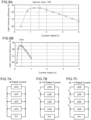
- the rising of the efficiency of the hydrogen gas production by a photocatalyst caused by the water temperature increase has been found out by an experiment as follows:
- a photocatalyst member obtained by spreading and sintering 100 mg SrTiOs (strontium titanate) on a glass plate was immersed in 200 ml of water put in a container made of silica glass, and while adjusting the water temperature to various values with a heater, the light of 365 nm was irradiated to the photocatalyst member at various light intensities by LED (maximum output 0.691W) of a spot type, whereby the decomposition reaction of water was induced, and hydrogen gas generated therefrom was collected and the generated amount of hydrogen gas was measured.
- the area irradiated with the light was 2 cm 2 .
- Photocatalyst efficiency % the generated amount of hydrogen gas H 2 ⁇ 2 / incident light amount , where the unit of the generated amount of hydrogen gas is mmol ⁇ cm -2 ⁇ hr -1 . (The reduced amount of hydrogen ions is twice of hydrogen gas.).
- the density of the light emitted from the above-mentioned light source device 4 may be adjusted so that the efficiency of hydrogen gas production will be improved. More in detail, according to the research of the inventors of the present invention, as already noted, it is found that the efficiency of hydrogen gas production (the produced amount of hydrogen gas per incident light amount) decreases as the density of the light irradiated to a photocatalyst is increased. Referring to Fig. 3B , according to experiments under the same conditions as Fig.
- the photocatalyst efficiency decreased with the increase of the LED output, i.e., the density of the irradiated light. This is considered because, even when the densities of excited electrons and electron holes generated in the photocatalyst are increased by the light intensity increase, the excited electrons and electron holes disappear by their recombination before reacting to water due to the slow speed of the decomposition reaction of water with excited electrons and electron holes.
- the ratio of photon energy which contributes to the generating of hydrogen gas decreases when the density of the light irradiated to the photocatalyst is increased.
- Fig. 3B it is understood that the change of the efficiency of hydrogen gas production is gradual if the light intensity is in the range below 0.1 W/cm 2 .
- the density of the light from the light source device 4 is adjusted to about 0.1 W/cm 2 or somewhat fewer than it in order to obtain more hydrogen gas.
- the area A cm 2 irradiated with the light from the light source device 4 may be adjusted to be P L /0.1 when the optical power from the light source device 4 is P L (W) so that the light intensity making the photocatalyst efficiency high will become 0.1 W/cm 2 or below.
- the area irradiated with light may be adjusted by adjusting the direction of a light reflector.
- the coat 12 of a photocatalyst material is applied on the outside surface of the housing 8.
- the material of the outside surface of the housing 8 was dissolved and the deterioration of the surface was observed.
- ultrapure water electric resistivity ⁇ 15M ⁇ -cm
- the light L from the light source device 4 penetrates the transparent plate 9 and propagates in the water W, and since the light is scattered in the water and reflected on a liquid surface and an inner surface of the container portion, the light propagates in various directions in the water as drawn by dotted arrows in the drawing, and the light which has penetrated the transparent plate 9 repeats the scattering and reflection and reaches also to the surface of the housing 8 at not small amount. So, if a photocatalytic reaction occurs also on the surface of the housing 8, the improvement of the efficiency of hydrogen gas production is expected.
- the surface of the housing 8 may be coated with the photocatalyst material 12 as noted above.
- the photocatalyst material coated on the surface of the housing 8 may be the same material as the photocatalyst bodies 3, and may be different photocatalyst materials.
- the photocatalyst material on the surface of the housing 8 is also a material having a sufficient activity to the light of the wavelength of the light from the light source.
- the container portion 2 may be provided with a structure for confining the light in the container portion 2 in order not to leak the light to the exterior thereof.
- the inner wall of the container portion 2 may be covered with a reflective mirror which reflects the light (light reflecting mechanism).
- the hydrogen gas producing apparatus 1 of the present embodiment there may be employed a plate member with photocatalyst material for a photocatalyst body 3 as schematically drawn in Fig. 4 .
- the photocatalyst body 3 may be formed in plate as illustrated, but, not limited thereto, when the photocatalyst material can be in contact with the water W.
- the photocatalyst body 3 may be formed by fixing a photocatalyst material on a substrate through overlaying powder of a photocatalyst material on a glass substrate or a ceramic board overall and heating to sinter it, or a substrate formed by hardening photocatalyst material in a plate form may be employed as the photocatalyst body 3. Further, for instance, there may be provided a stirring means 13 for generating convection of the water W in the container portion 2. Furthermore, when a plate member is employed as the photocatalyst body 3, particulate photocatalyst bodies 3 consisting of photocatalyst material may also be dispersed in the water to contribute the production of hydrogen gas.
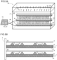
- a light source device 4 in which two or more light sources emitting light L are aligned is sunk in the water W in the container portion 2, and a plurality of such light source devices 4 may be arranged in the water.
- these light source devices 4 as schematically drawn on Fig.
- two or more light sources 5, which may be LEDs, are arranged on the housing 8 via a printed circuit board 6 and a heat conduction sheet 7, and around the respective light sources 5, there may be set light reflectors 10 collecting the light emitted from the light sources 5, and a transparent plate 9 is placed above each light source 5, whereby the light L from the light sources 5 may propagate into the water W through the transparent plates 9. Then, the outer surface of the housing 8 may be coated with the photocatalyst material 12. According to this structure, as shown in Fig.
- the light L emitted from one light source device 4 will be irradiated to the surface, coated with the photocatalyst material 12, of the housing 8 of another light source device 4, whereby the decomposition reaction of water by the photocatalyst occurs so that hydrogen gas can be produced.
- the light source device(s) 4 of the device 1 of the present embodiment is(are) operated by electric power, and preferably, that electric power may be given from energy of sunlight origin, which is generated in a solar panel, etc., or other renewable energy.
- the light source device(s) 4 may be designed to receive the supply of electric power through power lines 16 from a power production source by renewable energy, such as a solar panel 15.
- the light source device 4 emits light by receiving the supply of electric power from a power production source such as the solar panel 5, and the light is irradiated to the photocatalyst bodies 3 in the container portion 2. Further, the water W in the container portion 2 is warmed by the waste heat of the light source device 4. Then, in the photocatalyst material, the light is absorbed; excited electrons and electron holes are generated; hydrogen of the water is reduced by the excited electrons so that hydrogen gas will be formed, while oxygen of the water is oxidized by the electron holes so that oxygen gas will be formed.
- the generated hydrogen gas and oxygen gas pass through the gas pipe 2a, and are sent to a separator (not shown), where the hydrogen gas will be separated and collected.
- the separator may be, for instance, an arbitrary separator using a hydrogen separating membrane being used in this field.
- the electric power supplied to the light source device 4 may be that of renewable energy origin, such as from the solar panel 15.
- the electric power converted from solar energy for the light to be irradiated to a photocatalyst instead of the direct use of the sunlight, it is possible to convert the wavelength of the light into a wavelength band of light well absorbed by the photocatalyst and condense the density of the light, and thereby, the space occupied by the photocatalyst can be made small and the hydrogen gas producing apparatus can easily be miniaturized.
- the current supplied to the light source device 4 is adjusted so that the light-emitting efficiency of the light emitting element or light-emitting object will be maximized.
- the current amount in the light emitting element or light-emitting object may be adjusted so that the light-emitting efficiency will be maximized.
- a light emitting element or a light-emitting object is chosen so that the maximum light-emitting efficiency will be given when the current at the rated current value of the solar panel flows through it.
- a power production source by renewable energy such as a solar panel
- the output of the power production source varies depending upon its environmental conditions, such as the sunshine condition, and thus, the available current can vary every moment.
- the light source device operates in the condition that the light-emitting efficiency becomes maximized every moment, the good efficiency of the energy used for the production of hydrogen gas will be obtained.
- the light source device 4 of the present embodiment there may be employed a structure that two or more LEDs are connected in parallel as light emitting elements or light-emitting objects, as drawn in Fig. 7A - Fig. 7C .
- the number of LEDs connected to the power production source is adjusted in accordance with the output of the power production source, and thereby it will be configured that the current giving the maximum light-emitting efficiency as always as possible flows in the LEDs connected to the power production source.
- the output of the power production source is its rated power
- all of the LEDs may be connected to the power production source PV, as in Fig. 7A
- a half of LEDs may be connected to the power production source PV, as in Fig. 7B
- 1/4 of LEDs may be connected to the power production source PV, as shown in Fig. 7C .
- the electric power inputted to a LED is 5.664W (current 1.6A at 3.54V)
- the light-emitting efficiency of the LED is 32%
- the light-emitting output becomes 1.84W.
- the radiated light density in the photocatalyst bodies 3 is to be about 0.1 W/cm 2 giving the high photocatalyst efficiency
- it is preferable to adjust the irradiation area to be about 18.4 cm 2 .
- the position and direction of a light reflector and the interval of LEDs being placed may be set.
Landscapes
- Chemical & Material Sciences (AREA)
- Organic Chemistry (AREA)
- Health & Medical Sciences (AREA)
- General Health & Medical Sciences (AREA)
- Engineering & Computer Science (AREA)
- Combustion & Propulsion (AREA)
- Inorganic Chemistry (AREA)
- Catalysts (AREA)
- Led Device Packages (AREA)
- Led Devices (AREA)
Applications Claiming Priority (1)
| Application Number | Priority Date | Filing Date | Title |
|---|---|---|---|
| JP2021210009A JP7643997B2 (ja) | 2021-12-23 | 2021-12-23 | 光触媒を用いた水素ガス製造装置 |
Publications (3)
| Publication Number | Publication Date |
|---|---|
| EP4201876A2 true EP4201876A2 (de) | 2023-06-28 |
| EP4201876A3 EP4201876A3 (de) | 2023-09-20 |
| EP4201876B1 EP4201876B1 (de) | 2024-09-25 |
Family
ID=84569588
Family Applications (1)
| Application Number | Title | Priority Date | Filing Date |
|---|---|---|---|
| EP22215604.4A Active EP4201876B1 (de) | 2021-12-23 | 2022-12-21 | Vorrichtung zur herstellung von wasserstoffgas mittels photokatalysator |
Country Status (4)
| Country | Link |
|---|---|
| US (1) | US12434963B2 (de) |
| EP (1) | EP4201876B1 (de) |
| JP (1) | JP7643997B2 (de) |
| CN (1) | CN116332125B (de) |
Families Citing this family (2)
| Publication number | Priority date | Publication date | Assignee | Title |
|---|---|---|---|---|
| CN117285004B (zh) * | 2023-11-27 | 2024-02-20 | 中国科学院过程工程研究所 | 一种泛紫外聚光催化制氢装置、方法及用途 |
| CN117566687B (zh) * | 2024-01-18 | 2024-03-29 | 江苏中熙氢能源科技有限公司 | 一种雾化式光催化分解水制氢装置 |
Citations (6)
| Publication number | Priority date | Publication date | Assignee | Title |
|---|---|---|---|---|
| JPH09510657A (ja) | 1994-08-30 | 1997-10-28 | コリア リサーチ インスティテュート オブ ケミカル テクノロジー | 光触媒及びその製造方法とそれを用いた水素の製造方法 |
| JP2003251197A (ja) | 2002-03-06 | 2003-09-09 | National Institute For Materials Science | 可視光応答性稀土類化合物光触媒とそれを用いた水素の製造方法及び有害化学物質分解方法 |
| JP2013234077A (ja) | 2012-05-02 | 2013-11-21 | Toyota Industries Corp | 水素製造装置、及びそれを用いた水素製造方法 |
| JP2015218103A (ja) | 2014-05-21 | 2015-12-07 | トヨタ自動車株式会社 | 光触媒型水素製造装置 |
| JP2016108181A (ja) | 2014-12-05 | 2016-06-20 | 学校法人東京理科大学 | 二酸化炭素還元装置および還元方法 |
| JP2017024956A (ja) | 2015-07-27 | 2017-02-02 | 株式会社日立プラントメカニクス | 光触媒からなる電極を内蔵したレシーバによる水素発生システム |
Family Cites Families (5)
| Publication number | Priority date | Publication date | Assignee | Title |
|---|---|---|---|---|
| JP3233842B2 (ja) | 1995-11-17 | 2001-12-04 | 三菱重工業株式会社 | 水素製造方法及びその装置 |
| US7553464B2 (en) * | 2004-08-09 | 2009-06-30 | General Motors Corporation | Lanthanum tantalate photocatalysts |
| JP4905856B2 (ja) * | 2007-03-29 | 2012-03-28 | 東京電力株式会社 | 光触媒反応装置 |
| CN204503051U (zh) | 2015-03-07 | 2015-07-29 | 福建师范大学 | 一种光催化分解水制氢装置 |
| JP7355720B2 (ja) | 2020-10-11 | 2023-10-03 | トヨタ自動車株式会社 | 光触媒を用いた水素ガス製造装置 |
-
2021
- 2021-12-23 JP JP2021210009A patent/JP7643997B2/ja active Active
-
2022
- 2022-11-17 US US17/988,820 patent/US12434963B2/en active Active
- 2022-12-21 EP EP22215604.4A patent/EP4201876B1/de active Active
- 2022-12-21 CN CN202211650095.2A patent/CN116332125B/zh active Active
Patent Citations (6)
| Publication number | Priority date | Publication date | Assignee | Title |
|---|---|---|---|---|
| JPH09510657A (ja) | 1994-08-30 | 1997-10-28 | コリア リサーチ インスティテュート オブ ケミカル テクノロジー | 光触媒及びその製造方法とそれを用いた水素の製造方法 |
| JP2003251197A (ja) | 2002-03-06 | 2003-09-09 | National Institute For Materials Science | 可視光応答性稀土類化合物光触媒とそれを用いた水素の製造方法及び有害化学物質分解方法 |
| JP2013234077A (ja) | 2012-05-02 | 2013-11-21 | Toyota Industries Corp | 水素製造装置、及びそれを用いた水素製造方法 |
| JP2015218103A (ja) | 2014-05-21 | 2015-12-07 | トヨタ自動車株式会社 | 光触媒型水素製造装置 |
| JP2016108181A (ja) | 2014-12-05 | 2016-06-20 | 学校法人東京理科大学 | 二酸化炭素還元装置および還元方法 |
| JP2017024956A (ja) | 2015-07-27 | 2017-02-02 | 株式会社日立プラントメカニクス | 光触媒からなる電極を内蔵したレシーバによる水素発生システム |
Non-Patent Citations (1)
| Title |
|---|
| TSUYOSHI TAKATAJUNZHE JIANGYOSHIHISA SAKATAMAMIKO NAKABAYASHINAOYA SHIBATAVIKAS NANDALKAZUHIKO SEKITAKASHI HISATOMIKAZUNARI DOMEN: "Photocatalytic water splitting with a quantum efficiency of almost unity", NATURE, vol. 581, 2020, pages 411 - 414, XP037147962, DOI: 10.1038/s41586-020-2278-9 |
Also Published As
| Publication number | Publication date |
|---|---|
| JP7643997B2 (ja) | 2025-03-11 |
| JP2023094488A (ja) | 2023-07-05 |
| CN116332125A (zh) | 2023-06-27 |
| US12434963B2 (en) | 2025-10-07 |
| EP4201876A3 (de) | 2023-09-20 |
| CN116332125B (zh) | 2025-08-05 |
| EP4201876B1 (de) | 2024-09-25 |
| US20230202837A1 (en) | 2023-06-29 |
Similar Documents
| Publication | Publication Date | Title |
|---|---|---|
| CN114307861B (zh) | 使用了光催化剂的氢气制造装置 | |
| Chen et al. | Doped semiconductor nanomaterials | |
| EP4201876B1 (de) | Vorrichtung zur herstellung von wasserstoffgas mittels photokatalysator | |
| Su et al. | Photon upconversion in hetero-nanostructured photoanodes for enhanced near-infrared light harvesting | |
| Cao et al. | Artificial photosynthetic hydrogen evolution over gC 3 N 4 nanosheets coupled with cobaloxime | |
| US9738529B2 (en) | Method to reduce CO2 to CO using plasmon-enhanced photocatalysis | |
| Hu | Membrane-less photoelectrochemical devices for H 2 O 2 production: efficiency limit and operational constraint | |
| Pihosh et al. | Nanostructured tantalum nitride for enhanced solar water splitting | |
| Li et al. | Towards full‐spectrum photocatalysis: extending to the near‐infrared region | |
| US20200269219A1 (en) | Upconversion luminescence coupled to plasmonic metal nanostructures and photoactive material for photocatalysis | |
| CN115747854A (zh) | 一种太阳能驱动的光-电-热化学协同制氢系统 | |
| JP2007528935A (ja) | 水素を直接発生し、収集するための光電池 | |
| JP2003012569A (ja) | メタン又はメタノール生成システム | |
| JP3697591B2 (ja) | 薄膜光触媒化学変換装置 | |
| US12364977B1 (en) | Triphenylphosphine ruthenium photocatalyst for hydrogen production | |
| JP7736642B2 (ja) | 光触媒を用いた水素ガス製造装置 | |
| JO'M et al. | Photoproduction of hydrogen: Potential dependence of the quantum efficiency as a function of wavelength | |
| CN101971478B (zh) | 太阳能转换装置和方法 | |
| US20040038119A1 (en) | Device and method for converting heat and/or radiation energy into electric energy | |
| JP2005350293A (ja) | 水素生成ユニット及び水素発生装置 | |
| US20240261752A1 (en) | Hydrogen gas production device using photocatalyst | |
| JP2025025907A (ja) | 気体製造装置および気体製造方法 | |
| KR810001137B1 (ko) | 광화학 다이오드 | |
| US20260049404A1 (en) | Photoelectric cell with silicon carbide electrode and production method for same | |
| Rodríguez-Mendozat | Up-conversion processes in Ln (III)-doped luminescent materials for photovoltaics |
Legal Events
| Date | Code | Title | Description |
|---|---|---|---|
| PUAI | Public reference made under article 153(3) epc to a published international application that has entered the european phase |
Free format text: ORIGINAL CODE: 0009012 |
|
| STAA | Information on the status of an ep patent application or granted ep patent |
Free format text: STATUS: REQUEST FOR EXAMINATION WAS MADE |
|
| 17P | Request for examination filed |
Effective date: 20230107 |
|
| AK | Designated contracting states |
Kind code of ref document: A2 Designated state(s): AL AT BE BG CH CY CZ DE DK EE ES FI FR GB GR HR HU IE IS IT LI LT LU LV MC ME MK MT NL NO PL PT RO RS SE SI SK SM TR |
|
| PUAL | Search report despatched |
Free format text: ORIGINAL CODE: 0009013 |
|
| AK | Designated contracting states |
Kind code of ref document: A3 Designated state(s): AL AT BE BG CH CY CZ DE DK EE ES FI FR GB GR HR HU IE IS IT LI LT LU LV MC ME MK MT NL NO PL PT RO RS SE SI SK SM TR |
|
| RIC1 | Information provided on ipc code assigned before grant |
Ipc: B01J 7/02 20060101ALI20230811BHEP Ipc: B01J 35/00 20060101ALI20230811BHEP Ipc: C01B 3/04 20060101AFI20230811BHEP |
|
| REG | Reference to a national code |
Ref legal event code: R079 Ipc: B01J0019120000 Ref country code: DE Ref legal event code: R079 Ref document number: 602022006381 Country of ref document: DE Free format text: PREVIOUS MAIN CLASS: C01B0003040000 Ipc: B01J0019120000 |
|
| GRAP | Despatch of communication of intention to grant a patent |
Free format text: ORIGINAL CODE: EPIDOSNIGR1 |
|
| STAA | Information on the status of an ep patent application or granted ep patent |
Free format text: STATUS: GRANT OF PATENT IS INTENDED |
|
| RIC1 | Information provided on ipc code assigned before grant |
Ipc: C01B 3/04 20060101ALI20240412BHEP Ipc: B01J 19/12 20060101AFI20240412BHEP |
|
| INTG | Intention to grant announced |
Effective date: 20240502 |
|
| GRAS | Grant fee paid |
Free format text: ORIGINAL CODE: EPIDOSNIGR3 |
|
| GRAA | (expected) grant |
Free format text: ORIGINAL CODE: 0009210 |
|
| STAA | Information on the status of an ep patent application or granted ep patent |
Free format text: STATUS: THE PATENT HAS BEEN GRANTED |
|
| AK | Designated contracting states |
Kind code of ref document: B1 Designated state(s): AL AT BE BG CH CY CZ DE DK EE ES FI FR GB GR HR HU IE IS IT LI LT LU LV MC ME MK MT NL NO PL PT RO RS SE SI SK SM TR |
|
| REG | Reference to a national code |
Ref country code: GB Ref legal event code: FG4D |
|
| REG | Reference to a national code |
Ref country code: CH Ref legal event code: EP |
|
| REG | Reference to a national code |
Ref country code: DE Ref legal event code: R096 Ref document number: 602022006381 Country of ref document: DE |
|
| REG | Reference to a national code |
Ref country code: IE Ref legal event code: FG4D |
|
| P01 | Opt-out of the competence of the unified patent court (upc) registered |
Free format text: CASE NUMBER: APP_57268/2024 Effective date: 20241019 |
|
| REG | Reference to a national code |
Ref country code: LT Ref legal event code: MG9D |
|
| PG25 | Lapsed in a contracting state [announced via postgrant information from national office to epo] |
Ref country code: NO Free format text: LAPSE BECAUSE OF FAILURE TO SUBMIT A TRANSLATION OF THE DESCRIPTION OR TO PAY THE FEE WITHIN THE PRESCRIBED TIME-LIMIT Effective date: 20241225 |
|
| PG25 | Lapsed in a contracting state [announced via postgrant information from national office to epo] |
Ref country code: GR Free format text: LAPSE BECAUSE OF FAILURE TO SUBMIT A TRANSLATION OF THE DESCRIPTION OR TO PAY THE FEE WITHIN THE PRESCRIBED TIME-LIMIT Effective date: 20241226 Ref country code: FI Free format text: LAPSE BECAUSE OF FAILURE TO SUBMIT A TRANSLATION OF THE DESCRIPTION OR TO PAY THE FEE WITHIN THE PRESCRIBED TIME-LIMIT Effective date: 20240925 |
|
| PG25 | Lapsed in a contracting state [announced via postgrant information from national office to epo] |
Ref country code: BG Free format text: LAPSE BECAUSE OF FAILURE TO SUBMIT A TRANSLATION OF THE DESCRIPTION OR TO PAY THE FEE WITHIN THE PRESCRIBED TIME-LIMIT Effective date: 20240925 |
|
| PG25 | Lapsed in a contracting state [announced via postgrant information from national office to epo] |
Ref country code: LV Free format text: LAPSE BECAUSE OF FAILURE TO SUBMIT A TRANSLATION OF THE DESCRIPTION OR TO PAY THE FEE WITHIN THE PRESCRIBED TIME-LIMIT Effective date: 20240925 |
|
| PG25 | Lapsed in a contracting state [announced via postgrant information from national office to epo] |
Ref country code: RS Free format text: LAPSE BECAUSE OF FAILURE TO SUBMIT A TRANSLATION OF THE DESCRIPTION OR TO PAY THE FEE WITHIN THE PRESCRIBED TIME-LIMIT Effective date: 20241225 |
|
| REG | Reference to a national code |
Ref country code: NL Ref legal event code: MP Effective date: 20240925 |
|
| PG25 | Lapsed in a contracting state [announced via postgrant information from national office to epo] |
Ref country code: RS Free format text: LAPSE BECAUSE OF FAILURE TO SUBMIT A TRANSLATION OF THE DESCRIPTION OR TO PAY THE FEE WITHIN THE PRESCRIBED TIME-LIMIT Effective date: 20241225 Ref country code: NO Free format text: LAPSE BECAUSE OF FAILURE TO SUBMIT A TRANSLATION OF THE DESCRIPTION OR TO PAY THE FEE WITHIN THE PRESCRIBED TIME-LIMIT Effective date: 20241225 Ref country code: LV Free format text: LAPSE BECAUSE OF FAILURE TO SUBMIT A TRANSLATION OF THE DESCRIPTION OR TO PAY THE FEE WITHIN THE PRESCRIBED TIME-LIMIT Effective date: 20240925 Ref country code: GR Free format text: LAPSE BECAUSE OF FAILURE TO SUBMIT A TRANSLATION OF THE DESCRIPTION OR TO PAY THE FEE WITHIN THE PRESCRIBED TIME-LIMIT Effective date: 20241226 Ref country code: FI Free format text: LAPSE BECAUSE OF FAILURE TO SUBMIT A TRANSLATION OF THE DESCRIPTION OR TO PAY THE FEE WITHIN THE PRESCRIBED TIME-LIMIT Effective date: 20240925 Ref country code: BG Free format text: LAPSE BECAUSE OF FAILURE TO SUBMIT A TRANSLATION OF THE DESCRIPTION OR TO PAY THE FEE WITHIN THE PRESCRIBED TIME-LIMIT Effective date: 20240925 |
|
| REG | Reference to a national code |
Ref country code: AT Ref legal event code: MK05 Ref document number: 1726220 Country of ref document: AT Kind code of ref document: T Effective date: 20240925 |
|
| PG25 | Lapsed in a contracting state [announced via postgrant information from national office to epo] |
Ref country code: NL Free format text: LAPSE BECAUSE OF FAILURE TO SUBMIT A TRANSLATION OF THE DESCRIPTION OR TO PAY THE FEE WITHIN THE PRESCRIBED TIME-LIMIT Effective date: 20240925 |
|
| PG25 | Lapsed in a contracting state [announced via postgrant information from national office to epo] |
Ref country code: PT Free format text: LAPSE BECAUSE OF FAILURE TO SUBMIT A TRANSLATION OF THE DESCRIPTION OR TO PAY THE FEE WITHIN THE PRESCRIBED TIME-LIMIT Effective date: 20250127 Ref country code: IS Free format text: LAPSE BECAUSE OF FAILURE TO SUBMIT A TRANSLATION OF THE DESCRIPTION OR TO PAY THE FEE WITHIN THE PRESCRIBED TIME-LIMIT Effective date: 20250125 |
|
| PG25 | Lapsed in a contracting state [announced via postgrant information from national office to epo] |
Ref country code: RO Free format text: LAPSE BECAUSE OF FAILURE TO SUBMIT A TRANSLATION OF THE DESCRIPTION OR TO PAY THE FEE WITHIN THE PRESCRIBED TIME-LIMIT Effective date: 20240925 Ref country code: SM Free format text: LAPSE BECAUSE OF FAILURE TO SUBMIT A TRANSLATION OF THE DESCRIPTION OR TO PAY THE FEE WITHIN THE PRESCRIBED TIME-LIMIT Effective date: 20240925 |
|
| PG25 | Lapsed in a contracting state [announced via postgrant information from national office to epo] |
Ref country code: ES Free format text: LAPSE BECAUSE OF FAILURE TO SUBMIT A TRANSLATION OF THE DESCRIPTION OR TO PAY THE FEE WITHIN THE PRESCRIBED TIME-LIMIT Effective date: 20240925 |
|
| PG25 | Lapsed in a contracting state [announced via postgrant information from national office to epo] |
Ref country code: EE Free format text: LAPSE BECAUSE OF FAILURE TO SUBMIT A TRANSLATION OF THE DESCRIPTION OR TO PAY THE FEE WITHIN THE PRESCRIBED TIME-LIMIT Effective date: 20240925 Ref country code: AT Free format text: LAPSE BECAUSE OF FAILURE TO SUBMIT A TRANSLATION OF THE DESCRIPTION OR TO PAY THE FEE WITHIN THE PRESCRIBED TIME-LIMIT Effective date: 20240925 |
|
| PG25 | Lapsed in a contracting state [announced via postgrant information from national office to epo] |
Ref country code: CZ Free format text: LAPSE BECAUSE OF FAILURE TO SUBMIT A TRANSLATION OF THE DESCRIPTION OR TO PAY THE FEE WITHIN THE PRESCRIBED TIME-LIMIT Effective date: 20240925 Ref country code: PL Free format text: LAPSE BECAUSE OF FAILURE TO SUBMIT A TRANSLATION OF THE DESCRIPTION OR TO PAY THE FEE WITHIN THE PRESCRIBED TIME-LIMIT Effective date: 20240925 |
|
| PG25 | Lapsed in a contracting state [announced via postgrant information from national office to epo] |
Ref country code: SK Free format text: LAPSE BECAUSE OF FAILURE TO SUBMIT A TRANSLATION OF THE DESCRIPTION OR TO PAY THE FEE WITHIN THE PRESCRIBED TIME-LIMIT Effective date: 20240925 Ref country code: IT Free format text: LAPSE BECAUSE OF FAILURE TO SUBMIT A TRANSLATION OF THE DESCRIPTION OR TO PAY THE FEE WITHIN THE PRESCRIBED TIME-LIMIT Effective date: 20240925 |
|
| REG | Reference to a national code |
Ref country code: DE Ref legal event code: R097 Ref document number: 602022006381 Country of ref document: DE |
|
| PG25 | Lapsed in a contracting state [announced via postgrant information from national office to epo] |
Ref country code: MC Free format text: LAPSE BECAUSE OF FAILURE TO SUBMIT A TRANSLATION OF THE DESCRIPTION OR TO PAY THE FEE WITHIN THE PRESCRIBED TIME-LIMIT Effective date: 20240925 |
|
| PG25 | Lapsed in a contracting state [announced via postgrant information from national office to epo] |
Ref country code: DK Free format text: LAPSE BECAUSE OF FAILURE TO SUBMIT A TRANSLATION OF THE DESCRIPTION OR TO PAY THE FEE WITHIN THE PRESCRIBED TIME-LIMIT Effective date: 20240925 |
|
| PLBE | No opposition filed within time limit |
Free format text: ORIGINAL CODE: 0009261 |
|
| STAA | Information on the status of an ep patent application or granted ep patent |
Free format text: STATUS: NO OPPOSITION FILED WITHIN TIME LIMIT |
|
| PG25 | Lapsed in a contracting state [announced via postgrant information from national office to epo] |
Ref country code: LU Free format text: LAPSE BECAUSE OF NON-PAYMENT OF DUE FEES Effective date: 20241221 |
|
| 26N | No opposition filed |
Effective date: 20250626 |
|
| PG25 | Lapsed in a contracting state [announced via postgrant information from national office to epo] |
Ref country code: SE Free format text: LAPSE BECAUSE OF FAILURE TO SUBMIT A TRANSLATION OF THE DESCRIPTION OR TO PAY THE FEE WITHIN THE PRESCRIBED TIME-LIMIT Effective date: 20240925 |
|
| REG | Reference to a national code |
Ref country code: BE Ref legal event code: MM Effective date: 20241231 |
|
| PG25 | Lapsed in a contracting state [announced via postgrant information from national office to epo] |
Ref country code: BE Free format text: LAPSE BECAUSE OF NON-PAYMENT OF DUE FEES Effective date: 20241231 |
|
| PG25 | Lapsed in a contracting state [announced via postgrant information from national office to epo] |
Ref country code: IE Free format text: LAPSE BECAUSE OF NON-PAYMENT OF DUE FEES Effective date: 20241221 |
|
| PGFP | Annual fee paid to national office [announced via postgrant information from national office to epo] |
Ref country code: DE Payment date: 20251028 Year of fee payment: 4 |
|
| PG25 | Lapsed in a contracting state [announced via postgrant information from national office to epo] |
Ref country code: HR Free format text: LAPSE BECAUSE OF FAILURE TO SUBMIT A TRANSLATION OF THE DESCRIPTION OR TO PAY THE FEE WITHIN THE PRESCRIBED TIME-LIMIT Effective date: 20240925 |
|
| PGFP | Annual fee paid to national office [announced via postgrant information from national office to epo] |
Ref country code: FR Payment date: 20251117 Year of fee payment: 4 |