EP4202102A1 - Waschmaschine und wäschepflegevorrichtung - Google Patents
Waschmaschine und wäschepflegevorrichtung Download PDFInfo
- Publication number
- EP4202102A1 EP4202102A1 EP21929303.2A EP21929303A EP4202102A1 EP 4202102 A1 EP4202102 A1 EP 4202102A1 EP 21929303 A EP21929303 A EP 21929303A EP 4202102 A1 EP4202102 A1 EP 4202102A1
- Authority
- EP
- European Patent Office
- Prior art keywords
- panel
- frame
- washing machine
- control
- guide
- Prior art date
- Legal status (The legal status is an assumption and is not a legal conclusion. Google has not performed a legal analysis and makes no representation as to the accuracy of the status listed.)
- Pending
Links
Images







Classifications
-
- D—TEXTILES; PAPER
- D06—TREATMENT OF TEXTILES OR THE LIKE; LAUNDERING; FLEXIBLE MATERIALS NOT OTHERWISE PROVIDED FOR
- D06F—LAUNDERING, DRYING, IRONING, PRESSING OR FOLDING TEXTILE ARTICLES
- D06F34/00—Details of control systems for washing machines, washer-dryers or laundry dryers
- D06F34/28—Arrangements for program selection, e.g. control panels therefor; Arrangements for indicating program parameters, e.g. the selected program or its progress
- D06F34/34—Arrangements for program selection, e.g. control panels therefor; Arrangements for indicating program parameters, e.g. the selected program or its progress characterised by mounting or attachment features, e.g. detachable control panels or detachable display panels
-
- H—ELECTRICITY
- H05—ELECTRIC TECHNIQUES NOT OTHERWISE PROVIDED FOR
- H05K—PRINTED CIRCUITS; CASINGS OR CONSTRUCTIONAL DETAILS OF ELECTRIC APPARATUS; MANUFACTURE OF ASSEMBLAGES OF ELECTRICAL COMPONENTS
- H05K5/00—Casings, cabinets or drawers for electric apparatus
-
- D—TEXTILES; PAPER
- D06—TREATMENT OF TEXTILES OR THE LIKE; LAUNDERING; FLEXIBLE MATERIALS NOT OTHERWISE PROVIDED FOR
- D06F—LAUNDERING, DRYING, IRONING, PRESSING OR FOLDING TEXTILE ARTICLES
- D06F29/00—Combinations of a washing machine with other separate apparatus in a common frame or the like, e.g. with rinsing apparatus
- D06F29/005—Combinations of a washing machine with other separate apparatus in a common frame or the like, e.g. with rinsing apparatus the other separate apparatus being a drying appliance
-
- D—TEXTILES; PAPER
- D06—TREATMENT OF TEXTILES OR THE LIKE; LAUNDERING; FLEXIBLE MATERIALS NOT OTHERWISE PROVIDED FOR
- D06F—LAUNDERING, DRYING, IRONING, PRESSING OR FOLDING TEXTILE ARTICLES
- D06F34/00—Details of control systems for washing machines, washer-dryers or laundry dryers
- D06F34/08—Control circuits or arrangements thereof
Definitions
- the present disclosure relates to a washing machine and a clothes care apparatus, and more particularly, to a washing machine and a clothes care apparatus each including a control device on a front surface.
- a washing machine is an apparatus used to wash laundry by rotating a cylindrical drum, in which the laundry and wash water are retained, in a tub.
- Washing machines are classified into drum washing machines in which a drum is horizontally disposed and laundry is washed while being lifted and tumbled down along an inner circumferential wall of the drum during rotation of the drum about a horizontal axis in forward and reverse directions and pulsator washing machines in which a drum provided with a pulsator is vertically disposed and laundry is washed by using water streams generated by the pulsator while the drum rotates about a vertical axis in forward and reverse directions.
- a washing machine includes a cabinet defining an external appearance of the washing machine and having an inlet through which laundry is introduced, a tub installed in the cabinet to retain wash water, a drum to rotate in the tub by a rotational force of a motor, a door provided to open and close the inlet, and a control device configured to provide information on washing and detect an input of a user.
- the present disclosure is directed to a washing machine and a clothes care apparatus which allows a user to easily replace a control device of the washing machine and the clothes care apparatus.
- the present disclosure is directed to a washing machine and a clothes care apparatus which allows a user to easily maintain and repair a control device of the washing machine and the clothes care apparatus.
- a washing machine including: a cabinet including a top cover and a front surface; a drum rotatably disposed in the cabinet; and a control assembly configured to be mountable on the front surface of the cabinet and demountable from the front surface of the cabinet without removing the top cover of the cabinet, wherein the control assembly includes, a frame configured to be mountable on the front surface of the cabinet and demountable from the front surface of the cabinet; a control panel configured to be mountable on the frame and demountable from the frame and configured to be movable between a first position where the control panel is separable from the frame and a second position where the control panel is coupled to the frame; and a printed circuit board configured to control the washing machine, the printed circuit board interposed between the frame and the control panel.
- the frame may include a frame coupling part
- the control panel may include a panel coupling part configured to be couplable to the frame coupling part
- the frame may include a panel guide
- the control panel may include a coupling guide configured to be insertable into the panel guide while coupled to the frame.
- the panel guide may include an inclined portion formed to be inclined in a direction where the coupling guide is inserted into the panel guide.
- the coupling guide may be formed to prevent separation from the panel guide while the control panel is located at the second position.
- the control panel may include a fixing guide
- the frame may include a panel fixing part configured to guide movement of the fixing guide and coupled to the fixing guide by a panel fixing member while the control panel is located at the second position.
- the panel fixing member may be screw-coupled to the fixing guide and the panel fixing part.
- the panel fixing member may be formed to be wedge shaped and may include a first end and a second end, wherein the first end is adjacent to the second end while the panel fixing member is coupled to the fixing guide and the panel fixing part, and the first end and the second end are spaced apart to fix the fixing guide and the panel fixing part while the panel fixing member is coupled to the fixing guide and the panel fixing part
- the control panel may include a fixing guide
- the frame may include: a panel fixing part configured to guide movement of the fixing guide; and a panel support configured to be elastically deformed while the control panel is located at the first position, and restored while the control panel is at the second position to support the fixing guide.
- the cabinet may include a cabinet fixing part formed at a front surface
- the frame may include a frame fixing part formed to be fixed to the cabinet fixing part by a frame fixing member.
- the control assembly may be separable from the cabinet in the forward and backward direction.
- the control panel may include a module fixing part configured to fix the printed circuit board.
- the control device may include a rotatable controller on the control panel that is configured to be couplable to the printed circuit board.
- the frame may include a detergent case mount on which a detergent case is mountable.
- a clothes care apparatus including: a washing machine; and a clothing dryer configured to be mountable on the washing machine and demountable from the washing machine, wherein the washing machine includes: a cabinet having a top cover and a front surface; a drum rotatably disposed in the cabinet; and a control assembly mountable on a front surface of the cabinet and demountable from the front surface of the cabinet without removing the top cover while the clothing dryer is mounted on the washing machine, the control assembly including a frame configured to be mountable on the front surface of the cabinet and demountable from the front surface of the cabinet; a control panel configured to be mountable on the frame and demountable from the frame and configured to be movable between a first position where the control panel is separable from the frame and a second position where the control panel is coupled to the frame; and a printed circuit board configured to control the washing machine, the printed circuit board interposed between the control frame and the control panel.
- a washing machine including a cabinet including a front frame defining the front surface and a top cover constituting the upper surface, a tub disposed in the cabinet, a drum rotatably disposed in the tub, and a control device mounted on the cabinet to be separated therefrom in the forward and backward direction when the top cover is located on the front frame, wherein the control device includes a control frame detachably mounted on a front surface of the cabinet, a control panel detachably mounted on the control frame and provided to be movable between a first position where the control panel is detachable from the control frame and a second position where a forward and backward movement with reference to the control frame is limited, and a control module interposed between the control frame and the control panel.
- the control frame may include a frame coupling part
- the control panel may include a panel coupling part provided to be coupled to the frame coupling part.
- the control frame may include a panel guide, and the control panel may include a coupling guide provided to be guided by the panel guide when coupled to the control frame.
- the control panel may include a fixing guide
- the control frame may include a panel fixing part to guide movement of the fixing guide and coupled to the fixing guide by the panel fixing member when the control panel is located at the second position.
- the front frame may include a cabinet fixing part formed on the front surface
- the control frame may include a frame fixing part formed to be fixed to the cabinet fixing part by the frame fixing member.
- control panel In the first position the control panel may be separated from the frame.
- control panel In the second position the control panel may be connected to the frame.
- control device is coupled to the front surface of the cabinet in the washing machine and the clothes care apparatus, the control device may be easily replaced.
- control device is easily replaced in the washing machine and the clothes care apparatus, maintenance and/or repair of the control device may be easily performed.
- FIG. 1 is a view illustrating a washing machine according to an embodiment of the present disclosure.
- FIG. 2 is a side cross-sectional view of the washing machine of FIG. 1 .
- a washing machine 1 includes a cabinet 10 defining an external appearance, a tub 20 disposed in the cabinet 10, a drum 30 rotatably disposed in the tub 20, and a drive motor 40 configured to drive the drum 30.
- the cabinet 10 may include a front frame 13 constituting a front surface.
- An inlet 11 is formed in the front frame 13 of the cabinet 10 such that laundry is introduced into the drum 30.
- the inlet 11 is open and closed by a door 12 installed at a front surface of the cabinet 10.
- a water supply pipe 50 to supply wash water into the tub 20 is installed at an upper portion of the tub 20.
- One end of the water supply pipe 50 is connected to a water supply valve 56, and the other end of the water supply pipe 50 is connected to a detergent case 52.
- the detergent case 52 is connected to the tub 20 via a connection pipe 54. Water supplied through the water supply pipe 50 is supplied into the tub 20 together with a detergent after passing through the detergent case 52.
- the tub 20 is supported by a damper 70.
- the damper 70 connects the internal bottom surface of the cabinet 10 with the external surface of the tub 20.
- the drum 30 includes a cylinder part 31, a front plate 32 disposed at the front of the cylinder part 31, and a rear plate 33 disposed at the rear of the cylinder part 31.
- a plurality of through holes 34, through which wash water flows, are formed at the circumference of the drum 30, and a plurality of lifters 35, by which laundry is lifted and tumbled while the drum 30 is rotated, are installed at the inner circumference of the drum 30.
- the drum 30 is connected to the drive motor 40 via the shaft 90, and washing machines are classified, according to connection type between the shaft 90 and the drive motor 40, into a direct driving type in which the shaft 90 is directly connected to the drive motor 40 to rotate the drum 30, and an indirect driving type in which the shaft 90 is connected to the drive motor via a pulley 91 to drive the drum 30.
- the washing machine 1 may be provided as the indirect type, but the embodiment is not limited thereto, and technical features of the present disclosure may also be applied to the direct driving type.
- One end of the shaft 90 is connected to the rear plate 33 of the drum 30, and the other end of the shaft 90 extends to the outside of a rear portion 21 of the tub 20.
- the other end of the shaft 90 may be provided to be inserted into the pulley 91 to receive the drive power from the drive motor 40.
- a motor pulley 41 is formed at a rotation shaft of the drive motor 40.
- a drive belt 92 is provided between the motor pulley 41 and the pulley 91 and the shaft 90 may be driven by the drive belt 92.
- the drive motor 40 may be disposed at a portion below the tub 20 and drive the shaft 90 while the drive belt 92 rotates in a clockwise or counterclockwise direction in the upward and downward direction of the tub 20.
- a bearing housing 96 is installed at the rear portion 21 of the tub 20 to rotatable support the shaft 90.
- the bearing housing 96 may be formed of an aluminum alloy and may be inserted into the rear portion 21 of the tub 20 when the tub 20 is injection molded.
- a drain pump 80 to drain water contained in the tub 20 out of the cabinet 10
- a connection hose 82 to connect the tub 20 with the drain pump 82 to allow water contained in the tub 20 to flow into the drain pump 80
- a drain hose 84 to guide water pumped by the drain pump 80 out of the cabinet 10.
- a control device 100 may be disposed on the front frame 13 of the cabinet 10 to display a state of the washing machine 1 to a user or to receive an input to operate the washing machine 1 from the user.
- the control device 100 may also be referred to as control assembly 100.
- FIG. 3 is an exploded view of the control device of the washing machine illustrated in FIG. 1 .
- control device 100 may be provided to be mountable to and demountable from the front frame 13 of the washing machine 1.
- the control device 100 may include a control frame 110 (also referred to as frame 110) mountable to and demountable from the front frame 13, a control panel 130 mountable to and demountable from the control frame 110, and a control module 120 interposed between the control frame 110 and the control panel 130.
- a control frame 110 also referred to as frame 110
- control panel 130 mountable to and demountable from the control frame 110
- control module 120 interposed between the control frame 110 and the control panel 130.
- the front frame 13 may include a detergent case passage 19 through which the detergent case 52 passes.
- the control frame 110 may include a detergent case mount 119 on which the detergent case 52 is mounted.
- the detergent case mount 119 may be provided to correspond to the detergent case passage 19.
- FIG. 4 illustrates that the control frame is coupled to the front frame of the washing machine shown in FIG. 3 .
- FIG. 5 is a cross-sectional view illustrating that the control frame is mounted on the front frame of the washing machine illustrated in FIG. 4 and fixed thereto by a frame fixing member.
- control frame 110 may be coupled to the front frame 13 in the forward and backward direction.
- the front frame 13 may include a cabinet fixing part 14.
- the control frame 110 may include a frame fixing part 114 provided to correspond to the cabinet fixing part 14.
- control frame 110 may be fixed to the front frame 13 as a frame fixing member 106 passes through the frame fixing part 114 and the cabinet fixing part 14 in a state where the frame fixing part 114 is located on the front frame 13 to be aligned with the cabinet fixing part 14.
- the control frame 110 is fixed to the cabinet 10 by being coupled thereto in the forward and backward direction.
- the control frame 110 is not coupled to a top cover 18 of the cabinet 10 in the upward and downward direction.
- the control frame 110 is not coupled to the front frame 13 of the cabinet 10 in the upward and downward direction. Therefore, the control device 100 may be separated from the cabinet 10 without separating the top cover 18 from the cabinet 10.
- FIG. 6 shows that the control module is mounted on the control frame, which is mounted on the front frame of the washing machine illustrated in FIG. 5 , and the control panel is mounted thereon.
- FIG. 7 illustrates a portion of a front surface in which the control panel illustrated in FIG. 6 is coupled to the control frame at a first position.
- FIG. 8 illustrates portions of rear surfaces of the control panel and the control frame illustrated in FIG. 7 .
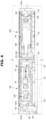
- FIG. 9 is a cross-sectional view taken along line A-A' of FIG. 8 .
- FIG. 10 is a cross-sectional view taken along line B-B' of FIG. 8 .
- FIG. 11 illustrates a portion of the front surface in which the control panel illustrated in FIG. 7 slides to a second position with reference to the control frame.
- FIG. 7 illustrates a portion of a front surface in which the control panel illustrated in FIG. 6 is coupled to the control frame at a first position.
- FIG. 8 illustrates portions of rear surfaces of the control panel and the control frame illustrated in FIG.
- FIG. 12 illustrates portions of the rear surfaces of the control panel and the control frame illustrated in FIG. 11 .
- FIG. 13 is a cross-sectional view taken along line C-C' of FIG. 12 .
- FIG. 14 is a cross-sectional view taken along line D-D' of FIG. 12 .
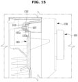
- FIG. 15 is a cross-sectional view taken along line E-E' of FIG. 11 .
- the control module 120 may be accommodated between the control frame 110 mounted on the front frame 13 and the control panel 130.
- the control module 120 may be fixed to the control panel 130.
- the control panel 130 may include a module fixing part 136 formed on the rear surface to fix the control module 120.
- the module fixing part 136 may be hooked to an edge of the control module 120.
- the control module 120 may be fixed to the control frame 110.
- the control module 120 may be coupled to the control frame 110 and/or the control panel 130 in the forward and backward direction.
- the control module 120 may include a printed circuit board (PCB).
- the control module 120 may be provided to control the washing machine 1.
- the control panel 130 may be coupled to the control frame 110 in the forward and backward direction.
- the control frame 110 may include a frame coupling part 111 to mount the control panel 130, a panel guide 112, and a panel fixing part 113.
- the control panel 130 may include a panel coupling part 131, a coupling guide 132, and a fixing guide 133.
- the front surface of the control panel 130 may be configured to include glass.
- the control device 100 may include a controller 101 provided to be operatable by the user.
- the controller 101 may be provided as a knob.
- the controller 101 may penetrate the control panel 130.
- the controller 101 may be provided to be rotatable about the control panel 130.
- the controller 101 may be couped to the control module 120.
- the panel coupling part 131 may be provided to correspond to the frame coupling part 111.
- the frame coupling part 111 may be formed as an opening.
- the panel coupling part 131 may be provided to be inserted into the frame coupling part 111.
- the frame coupling part 111 may support the panel coupling part 131 to prevent the panel coupling part 131 from being separated therefrom after the panel coupling part 131 is inserted thereinto and moves by a predetermined distance.
- a plurality of frame coupling parts 111 may be provided.
- a plurality of panel coupling parts 131 may be provided to correspond to the frame coupling parts 111.
- the coupling guide 132 may be provided to correspond to the panel guide 112.
- the panel guide 112 may be formed as an opening.
- the coupling guide 132 may be provided to be inserted into the panel guide 112.
- the panel guide 112 may support the coupling guide 132 to prevent the coupling guide 132 from being separated therefrom after the coupling guide 132 is inserted thereinto and moves by a predetermined distance.
- a plurality of panel guides 112 may be provided.
- a plurality of coupling guides 132 may be provided to correspond to the panel guides 112.
- the panel guide 112 may include an inclined portion 112a formed to guide the coupling guide 132 in an insertion direction.
- the inclined portion 112a may be formed to be inclined in a direction toward the center of the panel guide 112 in the insertion direction of the coupling guide 132 into the panel guide 112.
- the control panel 130 may be coupled to the control frame 110 at the first position shown in FIG. 7 .
- the panel fixing part 113 may be provided to correspond to the fixing guide 133.
- the panel fixing part 113 may have a groove shape.
- the fixing guide 133 may be provided to slide in a state being securely mounted on the panel fixing part 113.
- the panel fixing part 113 may guide the fixing guide 133 such that the control panel 130 moves between the first position and the second position with reference to the control frame 110.
- the control panel 130 may be fixed to the control frame 110 after being coupled to the control frame 110 at the first position as shown in FIG. 7 and then sliding into the second position as shown in FIG. 8 .
- control panel 130 may be coupled to the control frame 110 by aligning the fixing guide 133 to be securely mounted on the panel fixing part 113.
- control panel 130 may be coupled to the control frame 110 by aligning the coupling guide 132 to be inserted into the panel guide 112.
- the coupling guide 132 may guide the control panel 130 to be located at the first position with reference to the control frame 110 by the inclined portion 112a of the panel guide 112.
- control panel 130 may be coupled to the control frame 110 by aligning the panel coupling part 131 to be inserted into the frame coupling part 111.
- the control panel 130 may slide to the second position with reference to the control frame 110. Accordingly, a guide hole 133a of the fixing guide 133 may be aligned with a panel fixing hole 113a of the panel fixing part 113.
- the control panel 130 may be fixed to the control frame 110 as a panel fixing member 107 is coupled to the guide hole 133a and the panel fixing hole 113a in a state where the guide hole 133a of the fixing guide 133 is aligned with the panel fixing hole 113a of the panel fixing part 113.
- the panel fixing member 107 may be screw-coupled to the panel fixing hole 113a and the guide hole 133a.
- the coupling guide 132 moves to a position where separation thereof from the panel guide 112 is prevented. That is, in the case where a force is applied to the control panel 130 in a direction to separate the control panel 130 from the control frame 110 in a state where the control panel 130 is located at the second position with reference to the control frame 110, the coupling guide 132 is interrupted by the panel guide 112 so that separation from the panel guide 112 may be prevented.
- the panel coupling part 131 may be hooked by the frame coupling part 111. That is, the panel coupling part 131 moves in a position where separation from the frame coupling part 111 is prevented.
- the panel coupling part 131 is interrupted by the frame coupling part 111 so that separation from the frame coupling part 111 may be prevented.
- control device 100 may be separated from the cabinet 10 without separating the top cover 18 in the washing machine 1 according to an embodiment of the present disclosure, and thus the control device 100 may be easily replaced thereby facilitating maintenance and/or repair of the control device 100.
- control module 120 may be easily replaced.
- FIG. 16 illustrates another example of the panel fixing member illustrated in FIG. 15 .
- FIG. 16 a panel fixing member 207 for fixing the control panel 130 to the control frame 110 according to another embodiment will be described.
- the same reference numerals are assigned to the same components as those illustrated in FIG. 15 and detailed descriptions thereof may be omitted.
- the control panel 130 may be fixed to the control frame 110 by coupling the panel fixing member 207 to the guide hole 133a and the panel fixing hole 113a in a state where the guide hole 133a of the fixing guide 133 is aligned with the panel fixing hole 113a of the panel fixing part 113.
- the panel fixing member 207 may have a wedge shape.
- the panel fixing member 207 may be provided such that a first end 207a and a second end 207b become closer to each other in an insertion direction into the guide hole 133a and the panel fixing hole 113a.
- the first end 207a and the second end 207b of the panel fixing member 207 may become closer to each other.
- the panel fixing member 207 is coupled thereto after passing through the guide hole 133a and the panel fixing hole 113a, the first end 207a and the second end 207b of the panel fixing member 207 become farther from each other to prevent the panel fixing member 207 from being separated from the guide hole 133a and the panel fixing hole 113a.
- the panel fixing member 207 may be formed of a material with a predetermined elasticity.
- FIG. 17 illustrates a control pane of a control device is coupled to a control frame according to another embodiment of the present disclosure.
- FIG. 18 is a cross-sectional view taken along line F-F' of FIG. 17 .
- FIG. 19 illustrates that the control panel illustrated in FIG. 17 is fixed to the control frame.
- FIG. 20 is a cross-sectional view taken along line G-G' of FIG. 19 .
- FIGS. 17 to 20 a control device 300 according to another embodiment of the present disclosure will be described.
- the same reference numerals are assigned to the same components as those of the control device 100 illustrated in FIGS. 1 to 15 and detailed descriptions thereof may be omitted.
- a method of fixing a control panel 330 to a control frame 310 of the control device 300 is different from that of the control device 100 illustrated in FIGS. 1 to 15 .
- a panel fixing part 313 of the control device 300 may include a panel support 314.
- the panel fixing part 313 may have a groove shape.
- a fixing guide 333 of the control panel 330 may be slidably mounted on the panel fixing part 313.
- the panel support 314 may be formed of a material with a predetermined elasticity. Referring to FIG. 18 , when the control panel 330 is located at the first position with reference to the control frame 310, the panel support 314 may be pressed by the fixing guide 333 and deformed. Specifically, a supporting end 314a of the panel support 314 may be pressed by the fixing guide 333. The supporting end 314a may protrude from one surface of the panel support 314.
- the fixing guide 333 moves to a position not to press the panel support 314, and the panel support 314 returns to the previous position before the panel support 314 is pressed by a restoring force. Accordingly, the supporting end 314a of the panel support 314 supports the fixing guide 333 to prevent the fixing guide 333 from moving from the second position to the first position.
- control panel 330 may be detachably fixed to the control frame 310 using a simple manner in the control device 300 according to another embodiment of the present disclosure.
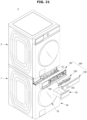
- FIG. 21 shows a clothes care apparatus including the washing machine illustrated in FIG. 1 .
- FIG. 21 a clothes care apparatus 3 in which a clothing dryer 2 is disposed on the washing machine 1 illustrated in FIG. 1 will be described.
- the control device 100 may be easily separated from the cabinet 10 without separating the clothing dryer 2 from the washing machine 1. That is, because the control device 100 of the washing machine 1 according to an embodiment of the present disclosure is provided to be separated from the front frame 13 of the cabinet 10 in the forward and backward direction, the control device 100 may be easily separated from the washing machine 1 without separating the clothing dryer 2 disposed thereon from the washing machine 1.
- the clothing dryer 2 disposed on the washing machine 1 is an example of a clothes care device, and the clothes care device disposed on the washing machine 1 may be a washing machine.
- FIG. 22 is a view illustrating that the control panel of the washing machine illustrated in FIG. 1 has been replaced.
- control device 100 illustrated in FIG. 1 may be separated from the cabinet 10 and a control device 100a having a different design from that of the control device 100 illustrated in FIG. 1 may be mounted thereon.
- the control device 100a illustrated in FIG. 22 may not only have a different design from that of the control device 100 of FIG. 1 but also be formed of a different material therefrom. Specifically, while the front surface of the control device 100 illustrated in FIG. 1 may be formed of glass, the front surface of the control device 100a illustrated in FIG. 22 may be formed of a metal.
- control device 100 may be easily separated from and mount on the cabinet 10 in the washing machine 1 according to an embodiment of the present disclosure, the control device 100 illustrated in FIG. 1 may be easily replaced with the control device 100a having a different design and/or including a different material.
Landscapes
- Engineering & Computer Science (AREA)
- Textile Engineering (AREA)
- Microelectronics & Electronic Packaging (AREA)
- Main Body Construction Of Washing Machines And Laundry Dryers (AREA)
Applications Claiming Priority (3)
| Application Number | Priority Date | Filing Date | Title |
|---|---|---|---|
| KR20210028528 | 2021-03-04 | ||
| KR1020210102478A KR20220125131A (ko) | 2021-03-04 | 2021-08-04 | 세탁기 및 의류관리장치 |
| PCT/KR2021/015835 WO2022186441A1 (ko) | 2021-03-04 | 2021-11-04 | 세탁기 및 의류관리장치 |
Publications (2)
| Publication Number | Publication Date |
|---|---|
| EP4202102A1 true EP4202102A1 (de) | 2023-06-28 |
| EP4202102A4 EP4202102A4 (de) | 2024-03-13 |
Family
ID=83116002
Family Applications (1)
| Application Number | Title | Priority Date | Filing Date |
|---|---|---|---|
| EP21929303.2A Pending EP4202102A4 (de) | 2021-03-04 | 2021-11-04 | Waschmaschine und wäschepflegevorrichtung |
Country Status (3)
| Country | Link |
|---|---|
| US (1) | US12012686B2 (de) |
| EP (1) | EP4202102A4 (de) |
| CN (1) | CN116368950A (de) |
Families Citing this family (3)
| Publication number | Priority date | Publication date | Assignee | Title |
|---|---|---|---|---|
| USD1010252S1 (en) * | 2022-07-15 | 2024-01-02 | Samsung Electronics Co., Ltd. | Washing machine |
| USD1010251S1 (en) * | 2022-07-15 | 2024-01-02 | Samsung Electronics Co., Ltd. | Washing machine |
| WO2024111819A1 (ko) * | 2022-11-22 | 2024-05-30 | 삼성전자주식회사 | 의류처리시스템 |
Family Cites Families (18)
| Publication number | Priority date | Publication date | Assignee | Title |
|---|---|---|---|---|
| US3756115A (en) * | 1971-12-03 | 1973-09-04 | Fastway Fasteners | Plastic rivet |
| KR100793763B1 (ko) * | 2000-12-18 | 2008-01-10 | 엘지전자 주식회사 | 스테인레스 외관 드럼세탁기의 디스플레이 기판 고정구조 |
| JP2005034414A (ja) | 2003-07-15 | 2005-02-10 | Matsushita Electric Ind Co Ltd | 洗濯機制御システム、洗濯機および端末 |
| DE10344918B4 (de) * | 2003-09-17 | 2009-12-17 | Prettl Appliance Systems Gmbh | Blendenanordnung für eine Haushaltsmaschine |
| KR101144996B1 (ko) | 2004-06-01 | 2012-05-11 | 엘지전자 주식회사 | 세탁기 콘솔의 조립구조 |
| KR101057713B1 (ko) | 2004-10-12 | 2011-08-18 | 주식회사 대우일렉트로닉스 | 드럼 세탁기의 컨트롤 패널 결합구조 |
| KR101263862B1 (ko) | 2005-05-23 | 2013-05-13 | 엘지전자 주식회사 | 세정 장치 |
| KR101285662B1 (ko) * | 2006-09-11 | 2013-07-11 | 엘지전자 주식회사 | 세탁 장치 |
| KR101306698B1 (ko) | 2006-09-05 | 2013-09-10 | 엘지전자 주식회사 | 위치 변경식 콘트롤러를 갖는 세탁 또는 세탁물 건조를위한 기계장치 |
| KR100710395B1 (ko) * | 2006-01-25 | 2007-04-24 | 엘지전자 주식회사 | 의류 건조기 |
| KR101275203B1 (ko) | 2006-02-14 | 2013-06-18 | 엘지전자 주식회사 | 세탁장치의 컨트롤 어셈블리 |
| KR101381144B1 (ko) | 2007-02-28 | 2014-04-04 | 삼성전자주식회사 | 세탁기의 세탁코스 추천방법 |
| KR20120075794A (ko) | 2010-12-29 | 2012-07-09 | 삼성전자주식회사 | 세탁기 |
| KR102049515B1 (ko) | 2013-02-07 | 2019-11-28 | 삼성전자주식회사 | 세탁기 |
| EP2837726B1 (de) | 2013-08-13 | 2016-10-12 | Electrolux Appliances Aktiebolag | Wäschebehandlungsvorrichtung mit einer Steuertafelanordnung |
| JP6788785B2 (ja) | 2015-04-09 | 2020-11-25 | パナソニックIpマネジメント株式会社 | 洗濯機 |
| KR101708350B1 (ko) * | 2015-11-02 | 2017-02-20 | 엘지전자 주식회사 | 의류처리장치 |
| PL3187647T3 (pl) * | 2015-12-29 | 2022-06-13 | Electrolux Appliances Aktiebolag | Urządzenie gospodarstwa domowego z płytką elektroniczną i sposób wytwarzania urządzenia gospodarstwa domowego |
-
2021
- 2021-11-04 EP EP21929303.2A patent/EP4202102A4/de active Pending
- 2021-11-04 CN CN202180070121.1A patent/CN116368950A/zh active Pending
-
2022
- 2022-04-04 US US17/712,396 patent/US12012686B2/en active Active
Also Published As
| Publication number | Publication date |
|---|---|
| CN116368950A (zh) | 2023-06-30 |
| EP4202102A4 (de) | 2024-03-13 |
| US20220282418A1 (en) | 2022-09-08 |
| US12012686B2 (en) | 2024-06-18 |
Similar Documents
| Publication | Publication Date | Title |
|---|---|---|
| US12012686B2 (en) | Washing machine and clothes care apparatus | |
| EP3189179B1 (de) | Waschmaschine | |
| KR20220125131A (ko) | 세탁기 및 의류관리장치 | |
| EP3879027B1 (de) | Waschmaschine | |
| KR102482469B1 (ko) | 세탁기 | |
| KR20240142377A (ko) | 세탁기 | |
| US20040107738A1 (en) | Washing machine and cabinet thereof | |
| KR101156707B1 (ko) | 드럼 세탁기와 드럼 세탁기 도어의 조립 방법 | |
| KR20230105099A (ko) | 세탁기 및 의류 처리 장치 | |
| EP3372723B1 (de) | Waschmaschine | |
| EP4353896B1 (de) | Waschmaschine | |
| KR20180074490A (ko) | 세탁기 | |
| KR102567517B1 (ko) | 세탁기 | |
| US11174580B2 (en) | Washing machine | |
| EP3543389B1 (de) | Waschmaschine | |
| US20040154909A1 (en) | Control panel assembly of washing machine | |
| EP3030707B1 (de) | Waschmaschine mit verbesserter kopplungsstruktur | |
| EP4357516A1 (de) | Waschmaschine und vorrichtung zur behandlung von kleidung | |
| KR20220099876A (ko) | 세탁기 | |
| US20180179687A1 (en) | Washing machine | |
| US7415846B2 (en) | Button assembly and washing machine having the same | |
| KR20220114709A (ko) | 세탁기 | |
| US12618188B2 (en) | Washing machine | |
| US20230272573A1 (en) | Washing machine | |
| EP4202110A1 (de) | Waschmaschine |
Legal Events
| Date | Code | Title | Description |
|---|---|---|---|
| STAA | Information on the status of an ep patent application or granted ep patent |
Free format text: STATUS: THE INTERNATIONAL PUBLICATION HAS BEEN MADE |
|
| PUAI | Public reference made under article 153(3) epc to a published international application that has entered the european phase |
Free format text: ORIGINAL CODE: 0009012 |
|
| STAA | Information on the status of an ep patent application or granted ep patent |
Free format text: STATUS: REQUEST FOR EXAMINATION WAS MADE |
|
| 17P | Request for examination filed |
Effective date: 20230321 |
|
| AK | Designated contracting states |
Kind code of ref document: A1 Designated state(s): AL AT BE BG CH CY CZ DE DK EE ES FI FR GB GR HR HU IE IS IT LI LT LU LV MC MK MT NL NO PL PT RO RS SE SI SK SM TR |
|
| A4 | Supplementary search report drawn up and despatched |
Effective date: 20240209 |
|
| RIC1 | Information provided on ipc code assigned before grant |
Ipc: D06F 34/08 20200101ALN20240205BHEP Ipc: G02F 1/1333 20060101ALN20240205BHEP Ipc: H05K 5/00 20060101ALI20240205BHEP Ipc: D06F 34/34 20200101AFI20240205BHEP |
|
| DAV | Request for validation of the european patent (deleted) | ||
| DAX | Request for extension of the european patent (deleted) | ||
| STAA | Information on the status of an ep patent application or granted ep patent |
Free format text: STATUS: EXAMINATION IS IN PROGRESS |
|
| 17Q | First examination report despatched |
Effective date: 20251104 |