EP4202103B1 - Appareil d'alimentation en détergent et machine à laver ayant celui-ci - Google Patents
Appareil d'alimentation en détergent et machine à laver ayant celui-ci Download PDFInfo
- Publication number
- EP4202103B1 EP4202103B1 EP21894952.7A EP21894952A EP4202103B1 EP 4202103 B1 EP4202103 B1 EP 4202103B1 EP 21894952 A EP21894952 A EP 21894952A EP 4202103 B1 EP4202103 B1 EP 4202103B1
- Authority
- EP
- European Patent Office
- Prior art keywords
- detergent
- housing
- water
- pump
- box
- Prior art date
- Legal status (The legal status is an assumption and is not a legal conclusion. Google has not performed a legal analysis and makes no representation as to the accuracy of the status listed.)
- Active
Links
Images








Classifications
-
- D—TEXTILES; PAPER
- D06—TREATMENT OF TEXTILES OR THE LIKE; LAUNDERING; FLEXIBLE MATERIALS NOT OTHERWISE PROVIDED FOR
- D06F—LAUNDERING, DRYING, IRONING, PRESSING OR FOLDING TEXTILE ARTICLES
- D06F39/00—Details of washing machines not specific to a single type of machines covered by groups D06F9/00 - D06F27/00
- D06F39/02—Devices for adding soap or other washing agents
- D06F39/024—Devices for adding soap or other washing agents mounted on the agitator or the rotating drum; Free body dispensers
-
- D—TEXTILES; PAPER
- D06—TREATMENT OF TEXTILES OR THE LIKE; LAUNDERING; FLEXIBLE MATERIALS NOT OTHERWISE PROVIDED FOR
- D06F—LAUNDERING, DRYING, IRONING, PRESSING OR FOLDING TEXTILE ARTICLES
- D06F39/00—Details of washing machines not specific to a single type of machines covered by groups D06F9/00 - D06F27/00
- D06F39/02—Devices for adding soap or other washing agents
- D06F39/022—Devices for adding soap or other washing agents in a liquid state
-
- D—TEXTILES; PAPER
- D06—TREATMENT OF TEXTILES OR THE LIKE; LAUNDERING; FLEXIBLE MATERIALS NOT OTHERWISE PROVIDED FOR
- D06F—LAUNDERING, DRYING, IRONING, PRESSING OR FOLDING TEXTILE ARTICLES
- D06F39/00—Details of washing machines not specific to a single type of machines covered by groups D06F9/00 - D06F27/00
- D06F39/08—Liquid supply or discharge arrangements
- D06F39/081—Safety arrangements for preventing water damage
-
- D—TEXTILES; PAPER
- D06—TREATMENT OF TEXTILES OR THE LIKE; LAUNDERING; FLEXIBLE MATERIALS NOT OTHERWISE PROVIDED FOR
- D06F—LAUNDERING, DRYING, IRONING, PRESSING OR FOLDING TEXTILE ARTICLES
- D06F39/00—Details of washing machines not specific to a single type of machines covered by groups D06F9/00 - D06F27/00
- D06F39/08—Liquid supply or discharge arrangements
- D06F39/083—Liquid discharge or recirculation arrangements
- D06F39/085—Arrangements or adaptations of pumps
-
- D—TEXTILES; PAPER
- D06—TREATMENT OF TEXTILES OR THE LIKE; LAUNDERING; FLEXIBLE MATERIALS NOT OTHERWISE PROVIDED FOR
- D06F—LAUNDERING, DRYING, IRONING, PRESSING OR FOLDING TEXTILE ARTICLES
- D06F39/00—Details of washing machines not specific to a single type of machines covered by groups D06F9/00 - D06F27/00
- D06F39/08—Liquid supply or discharge arrangements
- D06F39/083—Liquid discharge or recirculation arrangements
- D06F39/086—Arrangements for avoiding detergent wastage in the discharge conduit
-
- D—TEXTILES; PAPER
- D06—TREATMENT OF TEXTILES OR THE LIKE; LAUNDERING; FLEXIBLE MATERIALS NOT OTHERWISE PROVIDED FOR
- D06F—LAUNDERING, DRYING, IRONING, PRESSING OR FOLDING TEXTILE ARTICLES
- D06F39/00—Details of washing machines not specific to a single type of machines covered by groups D06F9/00 - D06F27/00
- D06F39/08—Liquid supply or discharge arrangements
- D06F39/088—Liquid supply arrangements
-
- D—TEXTILES; PAPER
- D06—TREATMENT OF TEXTILES OR THE LIKE; LAUNDERING; FLEXIBLE MATERIALS NOT OTHERWISE PROVIDED FOR
- D06F—LAUNDERING, DRYING, IRONING, PRESSING OR FOLDING TEXTILE ARTICLES
- D06F2103/00—Parameters monitored or detected for the control of domestic laundry washing machines, washer-dryers or laundry dryers
- D06F2103/42—Parameters monitored or detected for the control of domestic laundry washing machines, washer-dryers or laundry dryers related to filters or pumps
-
- D—TEXTILES; PAPER
- D06—TREATMENT OF TEXTILES OR THE LIKE; LAUNDERING; FLEXIBLE MATERIALS NOT OTHERWISE PROVIDED FOR
- D06F—LAUNDERING, DRYING, IRONING, PRESSING OR FOLDING TEXTILE ARTICLES
- D06F2105/00—Systems or parameters controlled or affected by the control systems of washing machines, washer-dryers or laundry dryers
- D06F2105/42—Detergent or additive supply
-
- D—TEXTILES; PAPER
- D06—TREATMENT OF TEXTILES OR THE LIKE; LAUNDERING; FLEXIBLE MATERIALS NOT OTHERWISE PROVIDED FOR
- D06F—LAUNDERING, DRYING, IRONING, PRESSING OR FOLDING TEXTILE ARTICLES
- D06F39/00—Details of washing machines not specific to a single type of machines covered by groups D06F9/00 - D06F27/00
- D06F39/12—Casings; Tubs
Definitions
- the invention relates to a washing machine improved to prevent hardening of detergent that has fallen to the bottom of a housing when a detergent box is separated from a detergent supply apparatus.
- a washing machine is a device that washes laundry using a driving force of a motor to agitate laundry, wash water, and detergent introduced into a washing tub together so that washing is performed by mutual friction.
- a detergent supply apparatus is an apparatus that allows a detergent to be evenly mixed and supplied together with water being supplied in a process of supplying water to the inside of a tub of the washing machine.
- the detergent is a liquid detergent
- the liquid detergent may be directly supplied into the tub.
- the detergent supply apparatus is provided to be embedded in a front portion of an upper part of a main body of the washing machine, and includes a box-shaped housing having a front that is openable, and a detergent box mounted to enter the housing through the open front of the housing and detachable in the form of a drawer.
- a washing machine equipped with a liquid detergent supply apparatus in which a detergent box has a detergent input space formed inside for a liquid detergent such that a liquid detergent, such as a rinsing agent and a bleach, is used.
- a liquid detergent such as a rinsing agent and a bleach
- a detergent pump may be fixed to the housing to perform pumping to suction a detergent in the detergent box and discharge the detergent to the housing.
- the detergent in the detergent box may be suctioned into the detergent pump by the detergent pump and then discharged into the housing.
- the detergent discharged into the housing may be supplied into the tub together with water being supplied.
- the detergent pump is provided with a detergent detecting unit for detecting the amount of a residual detergent.
- the detergent detecting unit is provided to, upon insufficiency of the detergent in the detergent box, display the result on a display unit of the washing machine.
- the display unit of the washing machine indicates that the detergent is insufficient
- the user undocks the detergent box from the detergent pump to replenish the detergent box.
- a detergent remaining in the detergent pump may fall to the bottom of the housing and may harden.
- the user may have an inconvenience of cleaning the detergent.
- the detergent detecting unit is installed in a suction portion, which suctions a detergent of the detergent box upon the detergent box being docked onto the detergent pump, to detect the amount of a remaining detergent.
- the detergent detecting unit is provided in a form of a pair of sensors installed in the suction portion, and since all of the pair of sensors need to be installed in the suction portion, the suction portion may need to have a large diameter. In proportion to the increasing diameter of the suction portion, the amount of the detergent remaining in the suction portion may increase when the detergent box is undocked from the detergent pump, in which case the amount of the detergent falling to the bottom of the housing may also increase.
- KR 2020 0017953 A discloses a washing machine which includes a detergent supply apparatus comprising a detergent box and a detergent pump.
- a detergent remaining in a detergent pump can be prevented from directly falling to the bottom of a housing when a detergent box is separated.
- the tub 20 may be provided to be elastically supported from the cabinet 10 by springs (not shown) provided on the upper side thereof and dampers 80 provided on the lower side thereof. That is, the springs and the dampers 80 absorb vibration energy between the tub 20 and the cabinet 10 when vibration generated during rotation of the drum 30 is transmitted to the tub 20 and the cabinet 10, thereby attenuating the vibration.
- the first detergent box 121 may include a first inlet 121a for injecting a detergent into the first detergent box 121 and a first cover 121b for opening and closing the first inlet 121a.
- the second detergent box 123 may include a second inlet 123a for injecting a detergent into the second detergent box 123 and a second cover 123b for opening and closing the second inlet 123a.
- the bent portion 126 may be provided on the upper side of the detergent discharge portion 125 as shown in FIG. 7 .
- the bent portion 126 may prevent the entry of the detergent discharge portion 125 from being exposed to the air. That is, when the end tip of the second bent portion 126b among the bent portions 126 is immersed in the detergent, the entry of the detergent discharge portion 125 may be prevented from being exposed to the air. As a result, the amount of unused detergent may be reduced by the length of the second bent portion 126b.
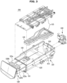
- the detergent pump 130 may be fixed to the rear side of the housing 110.
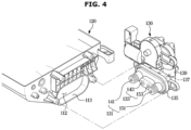
- the detergent pump 130 may include: a fixing portion 135 including a suction portion 131 configured to suction a detergent from the detergent box 120 upon the detergent pump 130 being docked onto the detergent pump, and a discharge portion 133 configured to discharge the detergent, which is suctioned to the suction portion 131, to the housing 110; and a pumping portion 137 configured to perform pumping such that the detergent is suctioned into the suction portion 131 and then discharged to the discharge portion 133.
- the pumping portion 137 may be formed inside a cylinder 139.
- the detergent pump 130 may include a first detergent pump 140 suctioning a detergent from the first detergent box 121 and discharging the suctioned detergent into the housing 110, and a second detergent pump 150 suctioning a detergent from the second detergent box 123 and discharging the suctioned detergent to the housing 110.
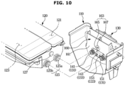
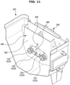
- the drain port 163 may be provided in a front lower portion of the water storage portion 161.
- the drain port 163 may include a drain hole 165 through which the water stored in the water storage portion 161 is drained, and a distribution groove 167 through which the water drained from the drain hole 165 is distributed and falls to the bottom of the housing 110.
- the drain hole 165 upon the detergent box 120 being docked onto the detergent pump 130, may be closed by the opening and closing member 127 of the detergent box 120. While the drain hole 165 is closed by the opening and closing member 127, water may be supplied from the water supply device 16 to fill the water storage portion 161 (see FIG. 1 ).
- the drain port 163 may include a drain hole 165 through which the water stored in the water storage portion 161 is drained, and a distribution rib 169 that allows the water drained from the drain hole 165 to be distributed and fall to the bottom of the housing 110.
- the configuration of the drain hole 165 and the configuration in which the drain hole 165 is opened and closed by the opening and closing member 127 of the detergent box 120 are the same as those shown in FIG. 8 , and thus descriptions thereof will be omitted.
- the distribution rib 169 may be provided on the rear side of the drain hole 165.
- the distribution rib 169 may be a V-shaped rib and may allow water falling from the drain hole 165 to be distributed and fall to the bottom of the housing 110.
- the distribution rib 169 may be provided in other forms as long as it can allow the water falling from the drain hole 165 to be distributed and fall to the bottom of the housing 110.
- FIG. 12 is a view illustrating a state in which a detergent detecting unit is fixed to a detergent pump according to an embodiment of the disclosure.
- the detergent pump 130 may be provided with a detergent detecting unit 170 for detecting the remaining amount of detergent.
- the detergent detecting unit 170 may be provided with a plurality of sensors.
- the detergent detecting unit 170 may be installed in the pumping portion 137 to detect the remaining amount of detergent.
- the detergent detecting unit 170 may be fixed to the outside of a cylinder 139 that forms the pumping portion 137.
- the detergent detecting unit 170 may include a first detecting unit 180 installed as a pair of sensors in the first pumping portion 145 and a second detecting unit 190 installed as a pair of sensors in the second pumping portion 155.
- the first detecting unit 180 may include a first sensor 181 and a second sensor 183 installed to have different heights based on the bottom of the housing 110.
- the first sensor 181 may be installed at a position lower than that of the second sensor 183.
- the remaining amount of detergent may be detected based on a difference in heights between the first sensor 181 and the second sensor 183. That is, when both the first sensor 181 and the second sensor 183 detect the detergent, the amount of detergent stored in the detergent box 120 may be sufficient for use.
- the insufficiency of the detergent may be delivered to the control unit, and may be displayed on the display unit 16b of the washing machine (see FIG. 1 )
- the diameter of the first suction portion 141 for suctioning a detergent from the detergent box 120 may be minimized. That is, when the first sensor 181 and the second sensor 183 for detecting the remaining amount of detergent are installed in the first suction portion 141, there is a restriction in minimizing the diameter of the first suction portion 141, but when both the first sensor 181 and the second sensor 183 are installed in the first pumping portion 145, the diameter of the first suction portion 141 may be minimized.
- the diameter of the first suction portion 141 is minimized, the amount of the detergent remaining in the first suction portion 141 upon the detergent box 120 being undocked from the detergent pump 130 may be reduced. Accordingly, the amount of the detergent falling from the detergent pump 130 to the bottom of the housing 110 upon the detergent box 120 being undocked from the detergent pump 130 may be reduced (see FIG. 14 ).
- the second detecting unit 190 may include a third sensor 191 and a fourth sensor 193 installed to have different heights based on the bottom of the housing 110.
- the third sensor 191 may be installed at a position lower than that of the fourth sensor 193.
- the remaining amount of detergent may be detected based on a difference in heights between the third sensor 191 and the fourth sensor 193. That is, when both the third sensor 191 and the fourth sensor 193 detect the detergent, the amount of detergent stored in the detergent box 120 may be sufficient for use.
- the insufficiency of the detergent may be delivered to the control unit, and may be displayed on the display unit 16b of the washing machine (see FIG. 1 )
- the diameter of the second suction portion 151 for suctioning a detergent from the detergent box 120 may be minimized. That is, when the third sensor 191 and the fourth sensor 193 for detecting the remaining amount of detergent are installed in the second suction portion 151, there is a restriction in minimizing the diameter of the second suction portion 151, but when both the third sensor 191 and the fourth sensor 193 are installed in the second pumping portion 155, the diameter of the second suction portion 151 may be minimized.
- the diameter of the second suction portion 151 is minimized, the amount of the detergent remaining in the second suction portion 151 upon the detergent box 120 being undocked from the detergent pump 130 may be reduced. Accordingly, the amount of the detergent falling from the detergent pump 130 to the bottom of the housing 110 upon the detergent box 120 being undocked from the detergent pump 130 may be reduced (see FIG. 14 ).
- the first sensor 181, installed at a lower position, of the first detecting unit 180 and the third sensor 191, installed at a lower position, of the second detecting unit 190 may be located at the same height.
- the second sensor 183, installed at a higher position, of the first detecting unit 180 and the fourth sensor 193, installed at a higher position, of the second detecting unit 190 may be located at the same height.
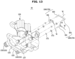
- FIG. 13 is a view illustrating a state in which a detergent detecting unit is fixed to a detergent pump according to another embodiment of the disclosure.
- the first sensor 181 and the third sensor 191 located at a shorter distance therebetween may be integrally formed with each other.
- the number of wires W individually connected to the first sensor 181 and the third sensor 191 may be reduced to one, thereby reducing the material costs.
- the first sensor 181 and the third sensor 191 located at a shorter distance therebetween may be integrally formed with each other, the first sensor 181 and the third sensor 191 may separately informed and connected to each other by a conductor. Even in this case in which the first sensor 181 and the third sensor 191 are connected to each other by a conductor, the number of wires W may be reduced to one, thereby reducing the material cost.
- the first sensor 181 and the third sensor 191 are illustrated as being located at a distance shorter than a distance between the second sensor 183 and the fourth sensor 193, and thus integrally formed with each other, but the disclosure is not limited thereto. That is, when the distance between the second sensor 183 and the fourth sensor 193 is shorter than the distance between the first sensor 181 and the third sensor 191, the second sensor 183 and the fourth sensor 193 located at a shorter distance may be integrally formed with each other. When the second sensor 183 and the fourth sensor 193 are integrally formed with each other, the number of wires W connected to the second sensor 183 and the fourth sensor 193 may be reduced to one, thereby reducing the material costs.
- the second sensor 183 and the fourth sensor 193 installed at a shorter distance therebetween may be integrally formed, the second sensor 183 and the fourth sensor 193 may be formed separately and connected to each other by a conductor. Even in this case in which the second sensor 183 and the fourth sensor 193 are connected to each other by a conductor, the number of wires W may be reduced to one, thereby reducing the material cost.
- FIG. 14 is a view illustrating a state in which, upon a detergent box being docked onto a detergent pump, a detergent in a detergent box is suctioned into the detergent pump according to an embodiment of the disclosure.
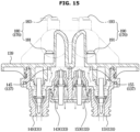
- FIG. 15 is a view illustrating a process in which, upon a detergent box being docked onto a detergent pump, a detergent suctioned by a suction portion of the detergent pump is discharged via a pumping portion to a discharge portion according to an embodiment of the disclosure.
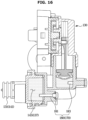
- FIG. 16 is a view illustrating a state in which, upon a detergent box being docked onto a detergent pump, a detergent detecting unit detects the remaining amount of detergent according to an embodiment of the disclosure.
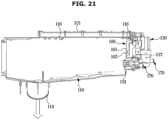
- FIG. 17 is a view illustrating a state in which, upon a detergent box being docked onto a detergent pump, a detergent in the detergent box is discharged to the bottom of a housing by a detergent pump, and water supplied through a water supply hole is stored in a water storage portion according to an embodiment of the disclosure.
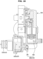
- FIG. 18 is a view illustrating a state in which a detergent detecting unit detects that the remaining amount of detergent is insufficient according to an embodiment of the disclosure.
- the detergent in the detergent box 120 may be suctioned into the first suction portion 141 through the first detergent discharge portion 125a by a pumping of the detergent pump 130.
- the detergent suctioned into the first suction portion 141 through the first detergent discharge portion 125a may be discharged to the first discharge portion 143 via the first pumping portion 145.
- the detergent suctioned into the second suction portion 151 through the second detergent discharge portion 125b may be discharged to the second discharge portion 153 through the second pumping portion 155.
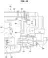
- both the first sensor 181 and the second sensor 183 of the detergent detecting unit 170 are immersed in the detergent, and thus the control unit may receive a signal indicating that the amount of the detergent is sufficient from the detergent detecting unit 170.
- the detergent box 120 may be withdrawn from the housing 110 to replenish the detergent in the detergent box 120.
- the opening and closing member 127 may open the drain hole 165 of the auxiliary tank 160 before the first detergent discharge portion 125a of the detergent box 120 is completely undocked from the first suction portion 141 of the detergent pump 130.
- water stored in the water storage portion 161 may fall to the bottom of the housing 110. The water falling to the bottom of the housing 110 may form a water film.
- the detergent remaining in the first suction portion 141 may fall onto the water film on the bottom of the housing 110. Since the detergent remaining in the first suction portion 141 does not directly fall to the bottom of the housing 110 but falls onto the water film, the detergent may be mixed with water and thus prevented from being hardened.
- the detergent that has fallen onto the water film of the bottom of the housing 110 may be supplied to the tub 20 together with water through the water supply portion 114 (see FIG. 1 ).
Landscapes
- Engineering & Computer Science (AREA)
- Textile Engineering (AREA)
- Detail Structures Of Washing Machines And Dryers (AREA)
Claims (15)
- Machine à laver comprenant :une enceinte (10) ;une cuve (20) prévue à l'intérieur de l'enceinte pour stocker de l'eau dans celle-ci ; etun appareil d'alimentation en détergent (100) conçu pour alimenter en détergent la cuve, l'appareil d'alimentation en détergent comprenant :un boîtier (110) prévu pour comporter une ouverture (111) sur un côté supérieur de la cuve ;un compartiment à détergent (120) prévu pour être inséré dans le boîtier et retiré de celui-ci par l'ouverture ;une pompe à détergent (130) fixée au boîtier pour permettre au compartiment à détergent d'être arrimé à celui-ci ou désarrimé de celui-ci, la pompe à détergent étant conçue pour, lorsque le compartiment à détergent est arrimé à la pompe à détergent, aspirer un détergent du compartiment à détergent et décharger le détergent dans le boîtier ;caractérisé en ce que la machine à laver comprend en outre :
un réservoir auxiliaire (160) prévu dans le boîtier pour stocker de l'eau dans celui-ci, et comprenant :une partie de stockage d'eau (161) dans laquelle l'eau est stockée, etun orifice de vidange (163) à travers lequel l'eau stockée dans la partie de stockage d'eau (161) est vidangée vers le fond du boîtier pour empêcher le détergent de durcir sur le fond du boîtier. - Machine à laver de la revendication 1, ladite ouverture (12) étant ménagée dans une partie avant du boîtier, et
ledit réservoir auxiliaire étant sur une paroi arrière à l'intérieur du boîtier. - Machine à laver de la revendication 1,
ledit orifice de vidange comprend un trou de vidange (165) à travers lequel l'eau est vidangée, et une rainure de distribution (167) formée sous la forme d'une rainure circulaire au niveau d'une circonférence du trou de vidange de sorte que l'eau vidangée en provenance du trou de vidange soit distribuée et tombe au fond du boîtier. - Machine à laver de la revendication 3, comprenant en outre :
un couvercle de boîtier (115) recouvrant un côté supérieur du boîtier et comprenant une pluralité de trous d'alimentation en eau (116) à travers lesquels l'eau peut être fournie au boîtier afin que l'eau fournie à travers certains de la pluralité de trous d'alimentation en eau tombe dans et soit stockée dans la partie de stockage d'eau (161). - Machine à laver de la revendication 3, ladite pompe à détergent (130) comprenant :une partie de fixation (135) comprenant une partie d'aspiration (131) conçue pour aspirer un détergent du compartiment à détergent (120) et une partie de décharge (133) conçue pour décharger le détergent, qui est aspiré dans la partie d'aspiration, dans le boîtier (110) ; etune partie de pompage (137) conçue pour réaliser un pompage afin que le détergent dans la boîte de détergent soit aspiré dans la partie d'aspiration, puis déchargé par la partie de décharge dans le boîtier.
- Machine à laver de la revendication 1,ledit orifice de vidange (163) comprenant un trou de vidange (165) à travers lequel l'eau est vidangée, etune nervure de distribution (169) sur un côté inférieur du trou de vidange qui distribue l'eau vidangée du trou de vidange vers le fond du boîtier.
- Machine à laver de la revendication 5, ledit compartiment à détergent comprenant :une partie de décharge de détergent (125) conçue pour être arrimée à la partie d'aspiration afin de décharger le détergent dans la partie d'aspiration, etun élément d'ouverture et de fermeture (127) conçu pour, lorsque la partie de décharge de détergent est arrimée à la partie d'aspiration (131), fermer le trou de vidange (165), et lorsque la partie de décharge de détergent est désarrimée de la partie d'aspiration, ouvrir le trou de vidange.
- Machine à laver de la revendication 7, ladite partie de décharge de détergent (125) et ledit élément d'ouverture et de fermeture (127) faisant chacun saillie vers l'arrière à partir d'une surface arrière du compartiment à détergent (120), la partie de décharge de détergent faisant saillie plus loin à partir de la surface arrière du compartiment à détergent que l'élément d'ouverture et de fermeture.
- Machine à laver de la revendication 8, ladite partie de décharge de détergent (125) étant formée pour faire saillie plus loin que l'élément d'ouverture et de fermeture (127) de sorte que, dans le cas où la partie de décharge de détergent est désarrimée de la partie d'aspiration, l'élément d'ouverture et de fermeture ouvre le trou de vidange avant que la partie de décharge de détergent ne soit complètement désarrimée de la partie d'aspiration.
- Machine à laver de la revendication 9, ledit compartiment à détergent (120) étant conçu afin qu'avant que la partie de décharge de détergent ne soit complètement désarrimée de la partie d'aspiration, l'eau stockée dans la partie de stockage d'eau soit vidangée vers le fond du boîtier à travers le trou de vidange (165).
- Machine à laver de la revendication 7, ledit boîtier comprenant :une partie d'ouverture (112) qui est ouverte pour permettre à une partie de la partie de fixation de passer à travers celle-ci,une partie de prolongement (113) s'étendant à partir de la partie d'ouverture, dans laquelle une partie restante de la partie de fixation (135) peut être insérée pour être fixée à la partie de prolongement, etune partie d'alimentation en eau (114) permettant au détergent déchargé de la partie de décharge dans le boîtier et à travers la partie d'ouverture d'être fourni à la cuve ensemble avec de l'eau.
- Machine à laver de la revendication 5,ledit compartiment à détergent (120) comprenant un premier compartiment à détergent (121) conçu pour contenir un détergent principal, et un second compartiment à détergent (123) conçu pour contenir un détergent préliminaire,ladite pompe à détergent (130) étant conçue pour aspirer et décharger individuellement dans le boîtier le détergent principal et le détergent préliminaire individuellement.
- Machine à laver de la revendication 12, ladite pompe à détergent (130) comprenant une première pompe à détergent (140) conçue pour aspirer le détergent principal du premier compartiment à détergent (121) et décharger le détergent principal dans le boîtier, et une seconde pompe à détergent (150) conçue pour aspirer le détergent préliminaire du second compartiment à détergent (123) et décharger le détergent préliminaire dans le boîtier.
- Machine à laver de la revendication 13, comprenant en outre :
une unité de détection de détergent (170) est installée dans la partie de pompage pour détecter le détergent restant dans la pompe à détergent, l'unité de détection de détergent comprenant une première unité de détection (180) comprenant un premier capteur (181) et un deuxième capteur (183) dans la première pompe à détergent (140) et une seconde unité de détection (190) comprenant un troisième capteur (191) et un quatrième capteur dans la seconde pompe à détergent (193). - Machine à laver de la revendication 14, ledit premier capteur (181) et ledit deuxième capteur (183) présentant des hauteurs différentes à partir du fond du boîtier, et ledit troisième capteur (191) et ledit quatrième capteur (193) présentant des hauteurs différentes à partir du fond du boîtier.
Applications Claiming Priority (2)
| Application Number | Priority Date | Filing Date | Title |
|---|---|---|---|
| KR1020200157553A KR20220070710A (ko) | 2020-11-23 | 2020-11-23 | 세제공급장치 및 이를 갖는 세탁기 |
| PCT/KR2021/015675 WO2022108181A1 (fr) | 2020-11-23 | 2021-11-02 | Appareil d'alimentation en détergent et machine à laver ayant celui-ci |
Publications (4)
| Publication Number | Publication Date |
|---|---|
| EP4202103A1 EP4202103A1 (fr) | 2023-06-28 |
| EP4202103A4 EP4202103A4 (fr) | 2023-12-20 |
| EP4202103B1 true EP4202103B1 (fr) | 2025-07-02 |
| EP4202103C0 EP4202103C0 (fr) | 2025-07-02 |
Family
ID=81709213
Family Applications (1)
| Application Number | Title | Priority Date | Filing Date |
|---|---|---|---|
| EP21894952.7A Active EP4202103B1 (fr) | 2020-11-23 | 2021-11-02 | Appareil d'alimentation en détergent et machine à laver ayant celui-ci |
Country Status (5)
| Country | Link |
|---|---|
| US (1) | US12480245B2 (fr) |
| EP (1) | EP4202103B1 (fr) |
| KR (1) | KR20220070710A (fr) |
| CN (1) | CN116261612A (fr) |
| WO (1) | WO2022108181A1 (fr) |
Families Citing this family (4)
| Publication number | Priority date | Publication date | Assignee | Title |
|---|---|---|---|---|
| TWD221653S (zh) * | 2021-12-01 | 2022-10-11 | 大陸商無錫小天鵝電器有限公司 | 洗衣機投放模組 |
| KR20240084826A (ko) * | 2022-12-07 | 2024-06-14 | 삼성전자주식회사 | 세제 공급 장치 및 이를 포함하는 세탁기 |
| EP4567182A4 (fr) * | 2023-02-02 | 2025-12-31 | Samsung Electronics Co Ltd | Lave-linge |
| KR20250032661A (ko) * | 2023-08-31 | 2025-03-07 | 삼성전자주식회사 | 의류처리장치 |
Family Cites Families (34)
| Publication number | Priority date | Publication date | Assignee | Title |
|---|---|---|---|---|
| KR940008602B1 (ko) | 1991-12-27 | 1994-09-24 | 삼성전자 주식회사 | 세탁기의 세제 투입장치 및 방법 |
| KR960015981B1 (ko) | 1994-01-14 | 1996-11-25 | 대우전자 주식회사 | 세탁기의 액체세제 투입장치 |
| KR0134735B1 (ko) | 1994-08-31 | 1998-04-23 | 배순훈 | 세제투입장치 |
| EP0849391A1 (fr) * | 1996-11-26 | 1998-06-24 | Unilever N.V. | Procédé et dispositif pour mélanger un détergent et un solubilisant |
| JP2002355494A (ja) * | 2001-06-01 | 2002-12-10 | Hitachi Ltd | 洗濯機 |
| KR100421883B1 (ko) | 2001-11-08 | 2004-03-09 | 엘지전자 주식회사 | 세탁기의 액체세제 투입장치 |
| DE60335445D1 (de) | 2003-02-19 | 2011-02-03 | Whirlpool Co | Waschmaschine mit Waschmittelverteiler |
| KR100987447B1 (ko) | 2003-10-16 | 2010-10-13 | 엘지전자 주식회사 | 세탁기의 세제 투입 장치 |
| KR20050118615A (ko) | 2004-06-14 | 2005-12-19 | 삼성전자주식회사 | 세탁기의 세제공급장치 |
| KR20070088212A (ko) | 2006-02-25 | 2007-08-29 | 엘지전자 주식회사 | 세탁기 및 세제공급기구의 세척방법 |
| KR20070117914A (ko) | 2006-06-09 | 2007-12-13 | 엘지전자 주식회사 | 세탁기의 세탁방법 |
| KR101330244B1 (ko) | 2006-11-21 | 2013-11-15 | 엘지전자 주식회사 | 세탁기의 세탁방법 |
| US8813526B2 (en) * | 2008-07-01 | 2014-08-26 | Whirlpool Corporation | Water flow paths in a household cleaning appliance with single use and bulk dispensing |
| KR20110082761A (ko) * | 2010-01-12 | 2011-07-20 | 주식회사 대우일렉트로닉스 | 액체세제용 펌프장치 |
| KR20120043214A (ko) * | 2010-10-26 | 2012-05-04 | 삼성전자주식회사 | 세탁기 |
| WO2013066118A1 (fr) | 2011-11-02 | 2013-05-10 | 주식회사 대우일렉트로닉스 | Appareil d'alimentation en eau pour machine à laver |
| KR20130048451A (ko) * | 2011-11-02 | 2013-05-10 | 동부대우전자 주식회사 | 세탁기의 급수장치 |
| KR20130131653A (ko) * | 2012-05-24 | 2013-12-04 | 삼성전자주식회사 | 세제공급장치 및 이를 갖춘 세탁기 |
| KR101992137B1 (ko) * | 2012-11-26 | 2019-06-25 | 삼성전자주식회사 | 액체감지장치, 세제공급장치 및 이를 가지는 세탁기 |
| KR101343712B1 (ko) * | 2013-07-16 | 2013-12-20 | 김학열 | 드럼세탁기의 세제공급통 |
| ITTO20130693A1 (it) * | 2013-08-14 | 2015-02-15 | Elbi Int Spa | Struttura di cassetto per l'erogazione dosata di almeno un agente di lavaggio in una macchina lavatrice, in particolare una macchina lavabiancheria. |
| KR102124478B1 (ko) * | 2013-10-30 | 2020-06-19 | 엘지전자 주식회사 | 의류처리장치 |
| WO2015074688A1 (fr) * | 2013-11-20 | 2015-05-28 | Electrolux Appliances Aktiebolag | Machine à laver le linge à tiroir à détergent comprenant un tableau de commande |
| WO2015178657A1 (fr) | 2014-05-22 | 2015-11-26 | Samsung Electronics Co., Ltd. | Machine à laver |
| KR20150135043A (ko) | 2014-05-22 | 2015-12-02 | 삼성전자주식회사 | 세탁기 |
| US11434597B2 (en) | 2017-04-17 | 2022-09-06 | Chongqing Haier Drum Washing Machine Co., Ltd. | Automatic delivery system for a washing machine and washing machine |
| CN108729133B (zh) | 2017-04-17 | 2020-10-16 | 青岛海尔滚筒洗衣机有限公司 | 一种洗衣机自动投放系统及洗衣机 |
| KR101932471B1 (ko) | 2017-07-19 | 2018-12-26 | 엘지전자 주식회사 | 의류처리장치 |
| CN110565336A (zh) * | 2018-06-06 | 2019-12-13 | 苏州三星电子有限公司 | 滚筒洗衣机用自动投料装置 |
| KR102565746B1 (ko) * | 2018-08-10 | 2023-08-11 | 삼성전자주식회사 | 세제공급장치 및 세탁기 |
| KR101992198B1 (ko) | 2018-12-18 | 2019-06-24 | 엘지전자 주식회사 | 의류처리장치 |
| KR102614493B1 (ko) | 2019-01-22 | 2023-12-15 | 엘지전자 주식회사 | 의류처리장치 |
| KR102628096B1 (ko) * | 2019-01-22 | 2024-01-23 | 엘지전자 주식회사 | 의류처리장치 |
| KR102582267B1 (ko) | 2019-04-12 | 2023-09-22 | 엘지전자 주식회사 | 세탁기 |
-
2020
- 2020-11-23 KR KR1020200157553A patent/KR20220070710A/ko active Pending
-
2021
- 2021-11-02 WO PCT/KR2021/015675 patent/WO2022108181A1/fr not_active Ceased
- 2021-11-02 EP EP21894952.7A patent/EP4202103B1/fr active Active
- 2021-11-02 CN CN202180067982.4A patent/CN116261612A/zh active Pending
-
2023
- 2023-03-23 US US18/125,340 patent/US12480245B2/en active Active
Also Published As
| Publication number | Publication date |
|---|---|
| EP4202103A4 (fr) | 2023-12-20 |
| US20230228026A1 (en) | 2023-07-20 |
| KR20220070710A (ko) | 2022-05-31 |
| WO2022108181A1 (fr) | 2022-05-27 |
| EP4202103C0 (fr) | 2025-07-02 |
| CN116261612A (zh) | 2023-06-13 |
| US12480245B2 (en) | 2025-11-25 |
| EP4202103A1 (fr) | 2023-06-28 |
Similar Documents
| Publication | Publication Date | Title |
|---|---|---|
| EP4202103B1 (fr) | Appareil d'alimentation en détergent et machine à laver ayant celui-ci | |
| EP2905369B1 (fr) | Appareil de traitement du linge | |
| EP1634987A1 (fr) | Lave-linge | |
| EP2719816B1 (fr) | Appareil de traitement du linge avec une dispositif de dissolution de détergent | |
| RU2597534C2 (ru) | Устройство подачи моющего средства и стиральная машина, имеющая такое устройство | |
| EP3239386B1 (fr) | Machine à laver | |
| KR101466523B1 (ko) | 자동 계량공급 시스템을 구비한 물 사용 가전 기기 및 자동 계량공급 방법 | |
| CN102587088A (zh) | 洗衣机 | |
| CN105308230A (zh) | 洗衣机 | |
| KR20140131809A (ko) | 자동 세제 공급장치 및 이를 갖는 세탁기 | |
| US20240376656A1 (en) | Washing machine and clothing treatment apparatus | |
| KR100487033B1 (ko) | 드럼식 세탁기 | |
| JP4275160B2 (ja) | ドラム式洗濯機 | |
| US7299663B2 (en) | Washing machine | |
| KR20240080858A (ko) | 의류처리장치의 제어방법 | |
| KR20240080859A (ko) | 의류처리장치의 제어방법 | |
| CN120225749A (zh) | 衣物处理设备 |
Legal Events
| Date | Code | Title | Description |
|---|---|---|---|
| STAA | Information on the status of an ep patent application or granted ep patent |
Free format text: STATUS: THE INTERNATIONAL PUBLICATION HAS BEEN MADE |
|
| PUAI | Public reference made under article 153(3) epc to a published international application that has entered the european phase |
Free format text: ORIGINAL CODE: 0009012 |
|
| STAA | Information on the status of an ep patent application or granted ep patent |
Free format text: STATUS: REQUEST FOR EXAMINATION WAS MADE |
|
| 17P | Request for examination filed |
Effective date: 20230321 |
|
| AK | Designated contracting states |
Kind code of ref document: A1 Designated state(s): AL AT BE BG CH CY CZ DE DK EE ES FI FR GB GR HR HU IE IS IT LI LT LU LV MC MK MT NL NO PL PT RO RS SE SI SK SM TR |
|
| A4 | Supplementary search report drawn up and despatched |
Effective date: 20231117 |
|
| RIC1 | Information provided on ipc code assigned before grant |
Ipc: D06F 39/08 20060101ALI20231113BHEP Ipc: D06F 39/02 20060101AFI20231113BHEP |
|
| DAV | Request for validation of the european patent (deleted) | ||
| DAX | Request for extension of the european patent (deleted) | ||
| GRAP | Despatch of communication of intention to grant a patent |
Free format text: ORIGINAL CODE: EPIDOSNIGR1 |
|
| STAA | Information on the status of an ep patent application or granted ep patent |
Free format text: STATUS: GRANT OF PATENT IS INTENDED |
|
| INTG | Intention to grant announced |
Effective date: 20250214 |
|
| GRAS | Grant fee paid |
Free format text: ORIGINAL CODE: EPIDOSNIGR3 |
|
| GRAA | (expected) grant |
Free format text: ORIGINAL CODE: 0009210 |
|
| STAA | Information on the status of an ep patent application or granted ep patent |
Free format text: STATUS: THE PATENT HAS BEEN GRANTED |
|
| AK | Designated contracting states |
Kind code of ref document: B1 Designated state(s): AL AT BE BG CH CY CZ DE DK EE ES FI FR GB GR HR HU IE IS IT LI LT LU LV MC MK MT NL NO PL PT RO RS SE SI SK SM TR |
|
| REG | Reference to a national code |
Ref country code: GB Ref legal event code: FG4D |
|
| REG | Reference to a national code |
Ref country code: CH Ref legal event code: EP |
|
| REG | Reference to a national code |
Ref country code: DE Ref legal event code: R096 Ref document number: 602021033581 Country of ref document: DE |
|
| REG | Reference to a national code |
Ref country code: IE Ref legal event code: FG4D |
|
| U01 | Request for unitary effect filed |
Effective date: 20250722 |
|
| U07 | Unitary effect registered |
Designated state(s): AT BE BG DE DK EE FI FR IT LT LU LV MT NL PT RO SE SI Effective date: 20250730 |
|
| U20 | Renewal fee for the european patent with unitary effect paid |
Year of fee payment: 5 Effective date: 20251124 |
|
| PG25 | Lapsed in a contracting state [announced via postgrant information from national office to epo] |
Ref country code: IS Free format text: LAPSE BECAUSE OF FAILURE TO SUBMIT A TRANSLATION OF THE DESCRIPTION OR TO PAY THE FEE WITHIN THE PRESCRIBED TIME-LIMIT Effective date: 20251102 |
|
| PGFP | Annual fee paid to national office [announced via postgrant information from national office to epo] |
Ref country code: GB Payment date: 20251001 Year of fee payment: 5 |
|
| PG25 | Lapsed in a contracting state [announced via postgrant information from national office to epo] |
Ref country code: NO Free format text: LAPSE BECAUSE OF FAILURE TO SUBMIT A TRANSLATION OF THE DESCRIPTION OR TO PAY THE FEE WITHIN THE PRESCRIBED TIME-LIMIT Effective date: 20251002 |
|
| PG25 | Lapsed in a contracting state [announced via postgrant information from national office to epo] |
Ref country code: HR Free format text: LAPSE BECAUSE OF FAILURE TO SUBMIT A TRANSLATION OF THE DESCRIPTION OR TO PAY THE FEE WITHIN THE PRESCRIBED TIME-LIMIT Effective date: 20250702 |
|
| PG25 | Lapsed in a contracting state [announced via postgrant information from national office to epo] |
Ref country code: GR Free format text: LAPSE BECAUSE OF FAILURE TO SUBMIT A TRANSLATION OF THE DESCRIPTION OR TO PAY THE FEE WITHIN THE PRESCRIBED TIME-LIMIT Effective date: 20251003 |
|
| PG25 | Lapsed in a contracting state [announced via postgrant information from national office to epo] |
Ref country code: CZ Free format text: LAPSE BECAUSE OF FAILURE TO SUBMIT A TRANSLATION OF THE DESCRIPTION OR TO PAY THE FEE WITHIN THE PRESCRIBED TIME-LIMIT Effective date: 20250702 |
|
| PG25 | Lapsed in a contracting state [announced via postgrant information from national office to epo] |
Ref country code: PL Free format text: LAPSE BECAUSE OF FAILURE TO SUBMIT A TRANSLATION OF THE DESCRIPTION OR TO PAY THE FEE WITHIN THE PRESCRIBED TIME-LIMIT Effective date: 20250702 |
|
| PG25 | Lapsed in a contracting state [announced via postgrant information from national office to epo] |
Ref country code: RS Free format text: LAPSE BECAUSE OF FAILURE TO SUBMIT A TRANSLATION OF THE DESCRIPTION OR TO PAY THE FEE WITHIN THE PRESCRIBED TIME-LIMIT Effective date: 20251002 |
|
| PG25 | Lapsed in a contracting state [announced via postgrant information from national office to epo] |
Ref country code: ES Free format text: LAPSE BECAUSE OF FAILURE TO SUBMIT A TRANSLATION OF THE DESCRIPTION OR TO PAY THE FEE WITHIN THE PRESCRIBED TIME-LIMIT Effective date: 20250702 |
|
| PG25 | Lapsed in a contracting state [announced via postgrant information from national office to epo] |
Ref country code: SM Free format text: LAPSE BECAUSE OF FAILURE TO SUBMIT A TRANSLATION OF THE DESCRIPTION OR TO PAY THE FEE WITHIN THE PRESCRIBED TIME-LIMIT Effective date: 20250702 |
|
| PG25 | Lapsed in a contracting state [announced via postgrant information from national office to epo] |
Ref country code: SK Free format text: LAPSE BECAUSE OF FAILURE TO SUBMIT A TRANSLATION OF THE DESCRIPTION OR TO PAY THE FEE WITHIN THE PRESCRIBED TIME-LIMIT Effective date: 20250702 |