EP4202158B1 - Zaunsystem - Google Patents
Zaunsystem Download PDFInfo
- Publication number
- EP4202158B1 EP4202158B1 EP22159379.1A EP22159379A EP4202158B1 EP 4202158 B1 EP4202158 B1 EP 4202158B1 EP 22159379 A EP22159379 A EP 22159379A EP 4202158 B1 EP4202158 B1 EP 4202158B1
- Authority
- EP
- European Patent Office
- Prior art keywords
- slats
- fencing system
- panel
- horizontal
- fixing
- Prior art date
- Legal status (The legal status is an assumption and is not a legal conclusion. Google has not performed a legal analysis and makes no representation as to the accuracy of the status listed.)
- Active
Links
Images


Classifications
-
- E—FIXED CONSTRUCTIONS
- E04—BUILDING
- E04H—BUILDINGS OR LIKE STRUCTURES FOR PARTICULAR PURPOSES; SWIMMING OR SPLASH BATHS OR POOLS; MASTS; FENCING; TENTS OR CANOPIES, IN GENERAL
- E04H17/00—Fencing, e.g. fences, enclosures, corrals
- E04H17/14—Fences constructed of rigid elements, e.g. with additional wire fillings or with posts
- E04H17/16—Fences constructed of rigid elements, e.g. with additional wire fillings or with posts using prefabricated panel-like elements, e.g. wired frames
- E04H17/161—Fences constructed of rigid elements, e.g. with additional wire fillings or with posts using prefabricated panel-like elements, e.g. wired frames using wire panels
- E04H17/164—Fences constructed of rigid elements, e.g. with additional wire fillings or with posts using prefabricated panel-like elements, e.g. wired frames using wire panels occultation devices therefor, e.g. slats, fence liners or panels blocking view therethrough
-
- E—FIXED CONSTRUCTIONS
- E04—BUILDING
- E04H—BUILDINGS OR LIKE STRUCTURES FOR PARTICULAR PURPOSES; SWIMMING OR SPLASH BATHS OR POOLS; MASTS; FENCING; TENTS OR CANOPIES, IN GENERAL
- E04H17/00—Fencing, e.g. fences, enclosures, corrals
- E04H17/14—Fences constructed of rigid elements, e.g. with additional wire fillings or with posts
- E04H17/16—Fences constructed of rigid elements, e.g. with additional wire fillings or with posts using prefabricated panel-like elements, e.g. wired frames
- E04H17/161—Fences constructed of rigid elements, e.g. with additional wire fillings or with posts using prefabricated panel-like elements, e.g. wired frames using wire panels
Definitions
- the present invention relates to a fencing system.
- the slats are compressed in their upper part against the wires by means of a finishing rail which mainly has a U-shaped configuration, which is fixed by clamping using fixing clips over the upper edge of the 3D panel and over the uppermost ends of the slats below the lowest horizontal wire.
- the slats are provided, on the side facing the wires, with a small downward-facing inclined lip which acts as a clip that prevents the slats from sliding downwards and with which the slats come to rest on the uppermost horizontal wire.
- the small lips are extruded together with the slat profiles and are bent outwards when in use.
- the disadvantage of the small lips is that they have the same minimal thickness as the wall thickness of the profiles, so they are not strong enough and cannot be further reinforced.
- a disadvantage associated with this is that when, in the case of incorrect assembly, the slats are removed from below out of the finishing rail, the small lip remains hooked behind the uppermost horizontal wire and is then folded back. upwards, so that there is a risk of breaking it, and certainly when it is necessary to repeat the disassembly and reassembly several times.
- the clamping of a finishing rail of this type is far from ideal and based on the movements of the finishing rail due to temperature fluctuations, the finishing rail can become deformed and detach by unclipping.
- the finishing rail is sized in such a way that it must rest in its upper part on the uppermost ends of the vertical wires of the 3D panel, so that it can be fixed using the fixing clips below the lowest horizontal wire of the panel, which has the disadvantage that the slats cannot protrude above the 3D panel, otherwise the finishing rail could not be fixed by snapping.
- EP3670790A1 aims to attach slats to existing fences using a connecting element independent of the material from which the slats are made and independent of the dimensions of the slats.
- a hole is provided in the slats from the front to the back of the slat.
- the connecting element consists of a head and one or more legs, the head being larger than the hole. The connecting element is inserted into the hole so that the head rests against the front of the slat and the legs protrude through the hole at the back to be attached to a horizontal wire of the fence.
- EP2924193B1 is intended to prevent the batten from loosening and/or rattling in the wind.
- a batten is provided with a hollow space at the bottom that is accessible from the underside of the batten.
- a bracket is provided with a hook-shaped portion that allows the support bracket to be attached to a horizontal wire of the mesh and a support portion with a lip that acts as an elastic clamping piece. The lip is inserted into the batten hollow space from the bottom of the batten so that the batten is supported from below and clamped with the rear wall.
- FR3081898A1 concerns the fixing of screening slats on rigid fences, the documents EP3249139B1 And EP3502379B1 also disclosing deck profiles that can be used for this purpose.
- the present invention aims to provide a solution for one or more of the aforementioned drawbacks as well as others.
- Fixing clips of this type can be easily applied and detached again by unsnapping several times without the risk of being damaged, in such a way that the problem of sagging can be avoided.
- the fixing clips are separate parts that do not have to be extruded as a component together with the slats, the fixing clips can be made to be as robust as needed so that they can be reused many times.
- the slats represent extruded hollow profiles made from a synthetic material, in which the fixing clips are inserted with their lips into the hollow of the slats, hooking into them, via a passage provided in the aforementioned support wall of the profiles.
- the fixing clips besides the aforementioned first lip, are also provided with a second lip which projects upwards along the outer edge of the supporting wall and the supporting wall of a slat in the assembled state is clamped between the two lips of the fixing clips.
- the fixing clip is provided with an elastic fixing clip bracket with which the fixing clip can be snapped onto the horizontal wire, wherein the fixing clip bracket is made in a tubular shape which has an opening whose width is less than that of the external diameter of the horizontal wire of the 3D panel on which the fixing clips are snapped.
- the free edges of the opening of the fixing clip yoke are folded back to form an entrance that extends into a conical-shaped configuration for a horizontal wire. Therefore, the fixing clips can be snap-fastened without the need for a tool.
- the clamping bars are preferably made from a synthetic material, in the form of elastic profiles which mainly have a V-shaped configuration, the tip of which is made with a concave shape which, in the assembled state, is inserted into the horizontal recess of the 3D panel against a horizontal grain in the recess, in such a way that the clamping bar is clamped between this horizontal grain and the slats.
- a finishing strip is applied which has a U-shaped configuration for aesthetic finishing reasons.
- the finishing strip is made in the form of an elastic profile in the form of a fixing clip which can be fixed by snapping over the fixing clips of the slats.
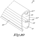
- the finishing rail is applied by snapping on with one leg over the fixing clips, the leg in question being provided, on its free edge, with a hook-shaped element folded inwards which, in the assembled state, hooks onto the fixing clips from below.
- the branch with the hook-shaped element on its inner side is provided with an elastic lip which, in the assembled state, exerts pressure on the vertical threads of the 3D panel, in such a way that the finishing rail is firmly fixed and cannot give rise to rattling.
- a gutter is formed by means of the hook-shaped element of the branch in question, with which the finishing rail can be arranged over the fixing clips and is thus protected against detachment or against unintentional upward sliding.
- the finishing rail protrudes, in the assembled state, with its base, over a certain distance, above the upper edge of the 3D panel.
- guides can be provided for insertion in order to be able to couple the finishing rails to each other in their reciprocal extension by means of connecting strips which can be inserted in a suitable manner into the guides. Consequently, the ends of the finishing rails connected to each other connect reciprocally while being perfectly aligned with each other.
- a fixing clip and a finishing rail which are designed to be applied in a fencing system as described above.
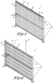
- the closing of the Figure 1 is built from 2 support stakes between which 3D wire panels are applied.
- 3D panels are known panels in the form of a wire mesh consisting of vertical wires 4 which are connected by means of horizontal wires 5, as shown in Figure 2 .
- the vertical wires 4 are provided, at determined heights above the ground, with a fold 6 which has a V-shaped configuration, which projects along one side of the panel 3 and which defines, along the other side, a horizontal recess 7.
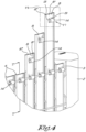
- the clamping bars 9 are made in the form of profiles from a synthetic material, which mainly have a V-shaped configuration, the tip of which is made with a concave-shaped hollow configuration 10 which, in the assembled state, is hooked, over the horizontal wire 5', to the base of the horizontal recess 7.
- the wedge enclosed between the branches 12 exhibits a capacity for elastic deformation, which makes it possible to obtain an elastic embedding by tightening the slats 8 against the horizontal wires 5.
- the slats 8 are produced in the example in the form of hollow profiles made of synthetic material which comprise a clamping wall 8' on the side of the clamping bars 9 and a support wall 8" on the opposite side, said support wall being applied by clamping against the horizontal wires 5.
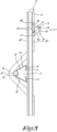
- the slats 8 are provided, near their uppermost ends, with a passage 13 made in the walls 8' and 8" which is intended to hold the slats 8 in the vertical direction by means of elastic fixing clips 14 which are fixed by snap-fastening between the vertical wires 4 over the uppermost horizontal wire 5 in the manner as can be seen in the figures 4 And 5 .
- the fixing clips 14 comprise a fixing clip detail in the form of a tubular-shaped fixing clip bracket 15 which comprises an opening 16 in its lower part with which the fixing clip 14 can be fixed by snap-fastening over the uppermost horizontal wire 5, wherein the width A of the opening 16 is less than the outer diameter B of the uppermost horizontal wire 5, where the fixing clip 14 is snap-fastened.
- edges 17 of the opening 16 of the bracket 15 of the fixing clip are folded back to form an entrance which extends into a conical-shaped configuration for a horizontal wire 5.
- the fixing clips 14 are provided, in their upper part, with a first hook-shaped lip 18 which projects upwards and which, in the assembled state, hooks through the recess 7 behind the support wall 8" into the hollow of the corresponding slat 8 in order to hold the slat in the vertical position.
- the fixing clip 8 is also provided with a second lip 19 which projects upwards and which, in the mounted state, exerts pressure on the external side of the supporting wall 8''.
- the lips 18 and 19 are designed in such a way that the supporting wall 8'' is clamped between them in the assembled state, as can be seen in Figure 5 .
- the clamping bars 9 are applied and held one by one in the recesses by sliding a first slat 8 between the clamping bars 9 and the horizontal wires 5 and then sliding a second slat in the same way in order to fix the clamping bars 9 which have been applied.
- the other slats 8 can be applied and each time fixed to the uppermost horizontal wire by means of the fixing clips 14 in order to obtain a dense partitioning as shown in Figure 2 .
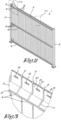
- one or more finishing rails 20 are applied at the top, which mainly have a U-shaped configuration, which are slid over the upper edge of the 3D panel 3 and over the uppermost ends of the slats 8.
- the finishing rail 20, as shown in Figure 10 is produced in the form of an elastic profile in the form of a fixing clip which can be fixed by snapping over the fixing clips 14 of the slats 8 with a branch 20' on the clamping side 8' of the slats 8 and with another branch 20" on the other side 8''.
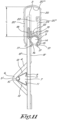
- the branch 20" is provided, at its free edge, with a hook-shaped element 20, folded inwards which, in the assembled state, hooks below the fixing clips 14, and which is provided, on its internal side, with an elastic lip 22 which, in the assembled state, exerts pressure on the vertical wires 4 of the 3D panel 3, as represented in Figure 11 .
- the lip 22 and the hook-shaped element 21 of the relevant branch 20" together define an open gutter 23 with which the finishing rail 20 is arranged over the fixing clips 14, as shown in Figure 11 .
- the fencing system is dimensioned in such a way that in the assembled state of the Figure 11 , there is still a free distance C between the base 20''' of the finishing rail 20 and the upper horizontal grain of the 3D panel, so that the system proves to be suitable for several lengths of spikes, that is to say for several lengths of the ends of the vertical wires above the upper horizontal grain.
- finishing rail 20 rests with the lip 22 on fixing clips 14, so that the finishing rail 20 cannot slide too deeply over the panel 3 and the slats 8.
- a guide 25 is provided in the finishing rails 20 for insertion.
Landscapes
- Engineering & Computer Science (AREA)
- Architecture (AREA)
- Civil Engineering (AREA)
- Structural Engineering (AREA)
- Fencing (AREA)
- Housing For Livestock And Birds (AREA)
Claims (15)
- Zaunsystem, das Folgendes umfasst:Stützpfähle (2), zwischen denen sogenannte 3D-Drahtpaneele (3) in der Form eines aus vertikalen Drähten (4) bestehenden Gitters angebracht sind, die mittels horizontaler Drähte (5) verbunden sind, wobei die vertikalen Drähte (4) in bestimmten Höhen mit einer Falte (6) versehen sind, die sich entlang einer einzigen Seite des Paneels erstreckt und eine horizontale Aussparung (7) definiert;eine Reihe von robusten Latten (8), die auf der Seite der Falte (6) zwischen den vertikalen Drähten (4) angebracht werden;wobei die Latten (8) mit einer Stützwand (8") gegen die horizontalen Drähte (5) mittels einer Klemmstange (9) zwischen den Latten und einem horizontalen Draht (5') in der Höhe von der horizontalen Aussparung (7) gepresst werden,die Latten (8) in der Nähe ihrer obersten Enden mit einem Durchgang (13) versehen sind;und die Latten (8) individuell mittels eines Befestigungsclips (14) gehalten werden, der mit einem Befestigungsclipdetail (15) versehen ist, das dazu bestimmt ist, den Befestigungsclip (14) durch Einrasten an einem horizontalen Draht (5) des 3D-Paneels (3) zu befestigen,
dadurch gekennzeichnet, dass die Latten (8) Hohlprofile darstellen, die aus einem Kunststoff hergestellt sind; wobei die Befestigungsclips (14) mit einer hakenförmigen Lippe (18) in Eingriff kommen, die durch den Durchgang (13) in der vorgenannten Stützwand (8") der Latten (8) nach oben in den Hohlraum der Latten (8) vorspringt, und wobeidie Befestigungsclips (14), neben der vorgenannten ersten Lippe (18) mit einer zweiten, nach oben ragenden Lippe (19) versehen sind, die in dem angebrachten Zustand sich entlang der Außenseite der Stützwand (8") befindet, wobei die Stützwand (8") zwischen den beiden Lippen (18, 19) der Befestigungsclips (14) eingeklemmt ist. - Zaunsystem nach Anspruch 1, dadurch gekennzeichnet, dass das Befestigungsclipdetail (15) des Befestigungsclips (14) in der Form eines Befestigungsclipbügels gebildet ist, mit dem der Befestigungsclip (14) durch Einrasten an dem horizontalen Draht (5) befestigt werden kann.
- Zaunsystem nach Anspruch 2, dadurch gekennzeichnet, dass der Bügel des Befestigungsclips in röhrenförmiger Form mit einer Öffnung (16) ausgebildet ist, deren Breite (A) kleiner ist als der Außendurchmesser (B) des horizontalen Drahtes (5) des 3D-Paneels (3) an der Stelle, wo der Befestigungsclip (14) einrasten soll.
- Zaunsystem nach Anspruch 3, dadurch gekennzeichnet, dass die freien Kanten (17) der Öffnung (16) des Bügels (15) des Befestigungsclips umgebogen sind, um einen Eingang zu erzielen, der sich in einer konisch geformten Konfiguration für einen horizontalen Draht (5) erstreckt.
- Zaunsystem nach einem der vorhergehenden Ansprüche, dadurch gekennzeichnet, dass die Befestigungsclips (14) dazu bestimmt sind, durch Einrasten am obersten horizontalen Draht (5) befestigt zu werden, und dass die Aussparung (13) in den Latten (8) so angebracht ist, dass in diesem Fall das oberste Ende der Latten (8) ungefähr auf der Höhe des obersten Endes des 3D-Paneels (3) liegt.
- System eines Zauns nach einem der vorhergehenden Ansprüche, dadurch gekennzeichnet, dass die Latten (8) und die Befestigungsclips (14) aus einem synthetischen Material hergestellt sind.
- Zaunsystem nach einem der vorhergehenden Ansprüche, dadurch gekennzeichnet, dass die Klemmstangen (9) in Form von Profilen ausgebildet sind, die überwiegend eine V-förmige Konfiguration bilden, deren Spitze mit einer konkav geformten, ausgehöhlten Konfiguration (10) ausgebildet ist, die in dem angebrachten Zustand in die horizontale Aussparung (7) des 3D-Paneels (3) gegen einen horizontalen Draht (5) in der Aussparung (7) eingreift.
- System eines Zauns nach Anspruch 7, dadurch gekennzeichnet, dass die freien Kanten (11) des Profils (9), das eine V-förmige Konfiguration besitzt, zueinander hin umgebogen sind.
- System eines Zauns nach einem der vorhergehenden Ansprüche, dadurch gekennzeichnet, dass eine U-förmig geformte Abschlussleiste (20) über die obere Kante des 3D-Paneels (3) und über die obersten Enden der Latten (8) aufgebracht wird.
- Zaunsystem nach Anspruch 9, dadurch gekennzeichnet, dass die Abschlussleiste (20) nach Art eines elastischen Profils in Form eines Befestigungsclips ausgebildet ist, der über die Befestigungsclips (14) der Latten (8) durch Einrasten befestigt werden kann.
- Zaunsystem nach Anspruch 9 oder 10, dadurch gekennzeichnet, dass die Abschlussleiste (20) mit einem Schenkel (20'') über den Befestigungsclips (14) durch Einrasten befestigt ist; wobei dieser Schenkel (20) an seiner untersten freien Kante mit einem nach innen gebogenen hakenförmigen Element (21) versehen ist, das in dem angebrachten Zustand unter die Befestigungsclips (14) greift.
- Zaunsystem nach Anspruch 11, dadurch gekennzeichnet, dass der Schenkel (20"), der das hakenförmige Element (21) umfasst, an seiner Innenseite mit einer elastischen Lippe (22) versehen ist, die in dem angebrachten Zustand einen Druck auf die vertikalen Drähte (4) des 3D-Paneels (3) ausübt.
- Zaunsystem nach Anspruch 11, dadurch gekennzeichnet, dass die Lippe (22) und das hakenförmige Element (21) des betreffenden Schenkels (20") eine offene Rinne (23) bilden, mit der die Abschlussleiste (20) über den Befestigungsclips (14) angebracht wird.
- Zaunsystem nach einem der Ansprüche 9 bis 13, dadurch gekennzeichnet, dass die Abschlussleiste (20) in dem angebrachten Zustand mit ihrer Basis (20") um eine gewisse Strecke (C) nach oben über die obere Kante des 3D-Paneels (3) hinausragt.
- Zaunsystem nach einem der Ansprüche 9 bis 14, dadurch gekennzeichnet, dass es mit Verbindungsstreifen (24) zur Verbindung von gegenseitigen Verlängerungen von angrenzenden Abschlussleisten (20) versehen ist; wobei hierzu in den Abschlussleisten (20) zum Einschieben bestimmte Führungen (25) vorgesehen sind, in denen die Verbindungsstreifen (24) geeignet verschiebbar sind.
Applications Claiming Priority (1)
| Application Number | Priority Date | Filing Date | Title |
|---|---|---|---|
| BE20216060A BE1030096B1 (nl) | 2021-12-24 | 2021-12-24 | Hekwerksysteem en daarbij horende clips en dekprofiel |
Publications (3)
| Publication Number | Publication Date |
|---|---|
| EP4202158A1 EP4202158A1 (de) | 2023-06-28 |
| EP4202158B1 true EP4202158B1 (de) | 2025-05-07 |
| EP4202158C0 EP4202158C0 (de) | 2025-05-07 |
Family
ID=80623696
Family Applications (1)
| Application Number | Title | Priority Date | Filing Date |
|---|---|---|---|
| EP22159379.1A Active EP4202158B1 (de) | 2021-12-24 | 2022-03-01 | Zaunsystem |
Country Status (3)
| Country | Link |
|---|---|
| EP (1) | EP4202158B1 (de) |
| BE (1) | BE1030096B1 (de) |
| ES (1) | ES3031696T3 (de) |
Families Citing this family (1)
| Publication number | Priority date | Publication date | Assignee | Title |
|---|---|---|---|---|
| CN220954980U (zh) * | 2023-07-11 | 2024-05-14 | 河北富晨贸易有限责任公司 | 一种挂钩及应用其的带压弯铁丝栅栏 |
Family Cites Families (5)
| Publication number | Priority date | Publication date | Assignee | Title |
|---|---|---|---|---|
| BE1021263B1 (nl) * | 2014-03-18 | 2015-10-13 | GENERALE MAATSCHAPPIJ VOOR PLASTIEK INTERNATIONAAL, naamloze vennootschap | Steunbeugel voor het ondersteunen van een lamel van een tuindraadpaneel |
| FR3051817B1 (fr) * | 2016-05-24 | 2020-10-30 | Sarl Clotures Et Portails De France | Ensemble d'habillage pour cloture treillis |
| BE1025808B1 (nl) * | 2017-12-21 | 2019-07-23 | GENERALE MAATSCHAPPIJ VOOR PLASTIEK INTERNATIONAAL, naamloze vennootschap | Kit voor het samenstellen van een tuindraadpaneel en verpakking, opslag en transport van kit en verpakking |
| FR3081898B1 (fr) * | 2018-05-31 | 2020-05-22 | Ap Extrusion Sas | Ensemble d'occultation pour cloture grillagee rigide |
| BE1026553B1 (nl) * | 2018-12-21 | 2020-03-16 | Plastivan Nv | Samenstelling en werkwijze voor het verticaal bevestigen van tuinlamellen aan een tuindraadpaneel |
-
2021
- 2021-12-24 BE BE20216060A patent/BE1030096B1/nl active IP Right Grant
-
2022
- 2022-03-01 EP EP22159379.1A patent/EP4202158B1/de active Active
- 2022-03-01 ES ES22159379T patent/ES3031696T3/es active Active
Also Published As
| Publication number | Publication date |
|---|---|
| BE1030096A1 (nl) | 2023-07-18 |
| ES3031696T3 (en) | 2025-07-10 |
| EP4202158C0 (de) | 2025-05-07 |
| EP4202158A1 (de) | 2023-06-28 |
| BE1030096B1 (nl) | 2023-07-25 |
Similar Documents
| Publication | Publication Date | Title |
|---|---|---|
| FR3018843B1 (fr) | Cloture, kit et procede pour l'installation de ladite cloture | |
| LU85061A1 (fr) | Dispositif et procede pour relier des claies de retenue et de consolidation | |
| EP3492675B1 (de) | Vorrichtung zum befestigen von lamellen an einem starren gitterpaneel, lamellenbefestigungskit an einem starren gitterpaneel und sichtschutzzaun, der mit diesem kit ausgestattet ist | |
| FR2569963A1 (fr) | Corniere support de plateau, panneau ou autre et meuble forme a l'aide de corniere de ce type | |
| FR2966987A1 (fr) | Plateaux de cables en treillis de fils pouvant etre accouples et procede pour reunir des sections dudit plateau | |
| EP0497690A1 (de) | Abdeckvorrichtung | |
| EP4202158A1 (de) | Zaunsystem sowie dazugehöriger befestigungsclip und dazugehörige abschlussleiste | |
| FR2616050A1 (fr) | Dispositif de solidarisation temporaire des extremites de deux structures dont au moins une est souple | |
| EP1306502A1 (de) | Zaunpfosten | |
| FR2516144A1 (fr) | Poteau de cloture | |
| EP0903452B1 (de) | Verbesserte Verbindungseinrichtung von Pfosten und Paneelen | |
| FR2716242A1 (fr) | Attache élastique en fil métallique pour la fixation de chemins de câbles sur leurs supports. | |
| EP0004504A2 (de) | Zaun mit einem vieleckigen Querschnitt aufweisenden Pfosten | |
| FR2922922A1 (fr) | Dispositif d'habillage de debordement de toiture. | |
| EP3006650B1 (de) | Gittervorrichtung zum erstellen eines zauns, und zaun ohne pfosten, der mithilfe einer solchen vorrichtung errichtet wird | |
| FR2888271A1 (fr) | Panneaux, poteaux de cloture et cloture comprenant de tels panneaux et poteaux | |
| EP0725467B1 (de) | Befestigungsvorrichtung zur Verbindung von Stahlblechkabelrinnen | |
| FR2591255A1 (fr) | Element d'aeration et de desaeration pour des bandes de montage de toitures | |
| FR3093748A1 (fr) | Lisse intermédiaire pour panneau de clôture, panneau de clôture intégrant une telle lisse, et clôture mettant en œuvre de tels panneaux de clôture | |
| FR2929767A1 (fr) | Profile de support de plateaux a mailles. | |
| FR2968334A1 (fr) | Cloture comprenant au moins un poteau et au moins un panneau nervure | |
| FR2968331A1 (fr) | Abri pour bassin d'agrement et profile adapte | |
| EP0137086B1 (de) | Bauvorrichtung einer aufgehängten Decke aus einer horizontal gespannten Folie | |
| FR2888056A1 (fr) | Structure de retenue amelioree, permettant l'ancrage d'un collier de serrage a l'interieur d'une goulotte ou la fixation d'une cloison de separation, et goulotte equipee d'une telle structure | |
| FR3132116A1 (fr) | Dispositif brise-vue ou d’occultation de clôtures en treillis rigide et panneau associé |
Legal Events
| Date | Code | Title | Description |
|---|---|---|---|
| PUAI | Public reference made under article 153(3) epc to a published international application that has entered the european phase |
Free format text: ORIGINAL CODE: 0009012 |
|
| STAA | Information on the status of an ep patent application or granted ep patent |
Free format text: STATUS: THE APPLICATION HAS BEEN PUBLISHED |
|
| STAA | Information on the status of an ep patent application or granted ep patent |
Free format text: STATUS: REQUEST FOR EXAMINATION WAS MADE |
|
| AK | Designated contracting states |
Kind code of ref document: A1 Designated state(s): AL AT BE BG CH CY CZ DE DK EE ES FI FR GB GR HR HU IE IS IT LI LT LU LV MC MK MT NL NO PL PT RO RS SE SI SK SM TR |
|
| 17P | Request for examination filed |
Effective date: 20230609 |
|
| RBV | Designated contracting states (corrected) |
Designated state(s): AL AT BE BG CH CY CZ DE DK EE ES FI FR GB GR HR HU IE IS IT LI LT LU LV MC MK MT NL NO PL PT RO RS SE SI SK SM TR |
|
| GRAP | Despatch of communication of intention to grant a patent |
Free format text: ORIGINAL CODE: EPIDOSNIGR1 |
|
| STAA | Information on the status of an ep patent application or granted ep patent |
Free format text: STATUS: GRANT OF PATENT IS INTENDED |
|
| INTG | Intention to grant announced |
Effective date: 20241008 |
|
| GRAS | Grant fee paid |
Free format text: ORIGINAL CODE: EPIDOSNIGR3 |
|
| GRAA | (expected) grant |
Free format text: ORIGINAL CODE: 0009210 |
|
| STAA | Information on the status of an ep patent application or granted ep patent |
Free format text: STATUS: THE PATENT HAS BEEN GRANTED |
|
| AK | Designated contracting states |
Kind code of ref document: B1 Designated state(s): AL AT BE BG CH CY CZ DE DK EE ES FI FR GB GR HR HU IE IS IT LI LT LU LV MC MK MT NL NO PL PT RO RS SE SI SK SM TR |
|
| REG | Reference to a national code |
Ref country code: GB Ref legal event code: FG4D Free format text: NOT ENGLISH |
|
| REG | Reference to a national code |
Ref country code: CH Ref legal event code: EP |
|
| REG | Reference to a national code |
Ref country code: DE Ref legal event code: R096 Ref document number: 602022014074 Country of ref document: DE |
|
| REG | Reference to a national code |
Ref country code: IE Ref legal event code: FG4D Free format text: LANGUAGE OF EP DOCUMENT: FRENCH |
|
| U01 | Request for unitary effect filed |
Effective date: 20250519 |
|
| U07 | Unitary effect registered |
Designated state(s): AT BE BG DE DK EE FI FR IT LT LU LV MT NL PT RO SE SI Effective date: 20250523 |
|
| REG | Reference to a national code |
Ref country code: ES Ref legal event code: FG2A Ref document number: 3031696 Country of ref document: ES Kind code of ref document: T3 Effective date: 20250710 |
|
| PG25 | Lapsed in a contracting state [announced via postgrant information from national office to epo] |
Ref country code: NO Free format text: LAPSE BECAUSE OF FAILURE TO SUBMIT A TRANSLATION OF THE DESCRIPTION OR TO PAY THE FEE WITHIN THE PRESCRIBED TIME-LIMIT Effective date: 20250807 |
|
| PG25 | Lapsed in a contracting state [announced via postgrant information from national office to epo] |
Ref country code: PL Free format text: LAPSE BECAUSE OF FAILURE TO SUBMIT A TRANSLATION OF THE DESCRIPTION OR TO PAY THE FEE WITHIN THE PRESCRIBED TIME-LIMIT Effective date: 20250507 |
|
| PG25 | Lapsed in a contracting state [announced via postgrant information from national office to epo] |
Ref country code: HR Free format text: LAPSE BECAUSE OF FAILURE TO SUBMIT A TRANSLATION OF THE DESCRIPTION OR TO PAY THE FEE WITHIN THE PRESCRIBED TIME-LIMIT Effective date: 20250507 |
|
| PG25 | Lapsed in a contracting state [announced via postgrant information from national office to epo] |
Ref country code: RS Free format text: LAPSE BECAUSE OF FAILURE TO SUBMIT A TRANSLATION OF THE DESCRIPTION OR TO PAY THE FEE WITHIN THE PRESCRIBED TIME-LIMIT Effective date: 20250807 |
|
| PG25 | Lapsed in a contracting state [announced via postgrant information from national office to epo] |
Ref country code: IS Free format text: LAPSE BECAUSE OF FAILURE TO SUBMIT A TRANSLATION OF THE DESCRIPTION OR TO PAY THE FEE WITHIN THE PRESCRIBED TIME-LIMIT Effective date: 20250907 |
|
| PG25 | Lapsed in a contracting state [announced via postgrant information from national office to epo] |
Ref country code: SM Free format text: LAPSE BECAUSE OF FAILURE TO SUBMIT A TRANSLATION OF THE DESCRIPTION OR TO PAY THE FEE WITHIN THE PRESCRIBED TIME-LIMIT Effective date: 20250507 |
|
| PG25 | Lapsed in a contracting state [announced via postgrant information from national office to epo] |
Ref country code: CZ Free format text: LAPSE BECAUSE OF FAILURE TO SUBMIT A TRANSLATION OF THE DESCRIPTION OR TO PAY THE FEE WITHIN THE PRESCRIBED TIME-LIMIT Effective date: 20250507 |
|
| PG25 | Lapsed in a contracting state [announced via postgrant information from national office to epo] |
Ref country code: SK Free format text: LAPSE BECAUSE OF FAILURE TO SUBMIT A TRANSLATION OF THE DESCRIPTION OR TO PAY THE FEE WITHIN THE PRESCRIBED TIME-LIMIT Effective date: 20250507 |
|
| PLBE | No opposition filed within time limit |
Free format text: ORIGINAL CODE: 0009261 |
|
| STAA | Information on the status of an ep patent application or granted ep patent |
Free format text: STATUS: NO OPPOSITION FILED WITHIN TIME LIMIT |
|
| REG | Reference to a national code |
Ref country code: CH Ref legal event code: L10 Free format text: ST27 STATUS EVENT CODE: U-0-0-L10-L00 (AS PROVIDED BY THE NATIONAL OFFICE) Effective date: 20260318 |
|
| REG | Reference to a national code |
Ref country code: CH Ref legal event code: U11 Free format text: ST27 STATUS EVENT CODE: U-0-0-U10-U11 (AS PROVIDED BY THE NATIONAL OFFICE) Effective date: 20260401 |
|
| 26N | No opposition filed |
Effective date: 20260210 |
|
| U20 | Renewal fee for the european patent with unitary effect paid |
Year of fee payment: 5 Effective date: 20260327 |
|
| PGFP | Annual fee paid to national office [announced via postgrant information from national office to epo] |
Ref country code: ES Payment date: 20260420 Year of fee payment: 5 |
|
| PGFP | Annual fee paid to national office [announced via postgrant information from national office to epo] |
Ref country code: CH Payment date: 20260401 Year of fee payment: 5 |