EP4202165A1 - Gasfederbefestigungssystem für ein scharnier für eine auf-/abhebetür - Google Patents
Gasfederbefestigungssystem für ein scharnier für eine auf-/abhebetür Download PDFInfo
- Publication number
- EP4202165A1 EP4202165A1 EP22211313.6A EP22211313A EP4202165A1 EP 4202165 A1 EP4202165 A1 EP 4202165A1 EP 22211313 A EP22211313 A EP 22211313A EP 4202165 A1 EP4202165 A1 EP 4202165A1
- Authority
- EP
- European Patent Office
- Prior art keywords
- door
- attachment
- base
- side panel
- coupling body
- Prior art date
- Legal status (The legal status is an assumption and is not a legal conclusion. Google has not performed a legal analysis and makes no representation as to the accuracy of the status listed.)
- Pending
Links
- 230000008878 coupling Effects 0.000 claims abstract description 40
- 238000010168 coupling process Methods 0.000 claims abstract description 40
- 238000005859 coupling reaction Methods 0.000 claims abstract description 40
- 229910000831 Steel Inorganic materials 0.000 claims description 2
- 230000000903 blocking effect Effects 0.000 claims description 2
- 239000010959 steel Substances 0.000 claims description 2
- 230000006870 function Effects 0.000 description 3
- 238000010276 construction Methods 0.000 description 2
- 238000005452 bending Methods 0.000 description 1
- 230000000295 complement effect Effects 0.000 description 1
- 239000011521 glass Substances 0.000 description 1
- 230000005484 gravity Effects 0.000 description 1
- 238000003780 insertion Methods 0.000 description 1
- 230000037431 insertion Effects 0.000 description 1
Images




Classifications
-
- E—FIXED CONSTRUCTIONS
- E05—LOCKS; KEYS; WINDOW OR DOOR FITTINGS; SAFES
- E05F—DEVICES FOR MOVING WINGS INTO OPEN OR CLOSED POSITION; CHECKS FOR WINGS; WING FITTINGS NOT OTHERWISE PROVIDED FOR, CONCERNED WITH THE FUNCTIONING OF THE WING
- E05F1/00—Closers or openers for wings, not otherwise provided for in this subclass
- E05F1/08—Closers or openers for wings, not otherwise provided for in this subclass spring-actuated, e.g. for horizontally sliding wings
- E05F1/10—Closers or openers for wings, not otherwise provided for in this subclass spring-actuated, e.g. for horizontally sliding wings for swinging wings, e.g. counterbalance
- E05F1/1091—Closers or openers for wings, not otherwise provided for in this subclass spring-actuated, e.g. for horizontally sliding wings for swinging wings, e.g. counterbalance with a gas spring
-
- E—FIXED CONSTRUCTIONS
- E05—LOCKS; KEYS; WINDOW OR DOOR FITTINGS; SAFES
- E05Y—INDEXING SCHEME ASSOCIATED WITH SUBCLASSES E05D AND E05F, RELATING TO CONSTRUCTION ELEMENTS, ELECTRIC CONTROL, POWER SUPPLY, POWER SIGNAL OR TRANSMISSION, USER INTERFACES, MOUNTING OR COUPLING, DETAILS, ACCESSORIES, AUXILIARY OPERATIONS NOT OTHERWISE PROVIDED FOR, APPLICATION THEREOF
- E05Y2201/00—Constructional elements; Accessories therefor
- E05Y2201/60—Suspension or transmission members; Accessories therefor
- E05Y2201/622—Suspension or transmission members elements
- E05Y2201/628—Bearings
- E05Y2201/636—Universal or ball joints
-
- E—FIXED CONSTRUCTIONS
- E05—LOCKS; KEYS; WINDOW OR DOOR FITTINGS; SAFES
- E05Y—INDEXING SCHEME ASSOCIATED WITH SUBCLASSES E05D AND E05F, RELATING TO CONSTRUCTION ELEMENTS, ELECTRIC CONTROL, POWER SUPPLY, POWER SIGNAL OR TRANSMISSION, USER INTERFACES, MOUNTING OR COUPLING, DETAILS, ACCESSORIES, AUXILIARY OPERATIONS NOT OTHERWISE PROVIDED FOR, APPLICATION THEREOF
- E05Y2600/00—Mounting or coupling arrangements for elements provided for in this subclass
- E05Y2600/60—Mounting or coupling members; Accessories therefor
- E05Y2600/63—Retainers
-
- E—FIXED CONSTRUCTIONS
- E05—LOCKS; KEYS; WINDOW OR DOOR FITTINGS; SAFES
- E05Y—INDEXING SCHEME ASSOCIATED WITH SUBCLASSES E05D AND E05F, RELATING TO CONSTRUCTION ELEMENTS, ELECTRIC CONTROL, POWER SUPPLY, POWER SIGNAL OR TRANSMISSION, USER INTERFACES, MOUNTING OR COUPLING, DETAILS, ACCESSORIES, AUXILIARY OPERATIONS NOT OTHERWISE PROVIDED FOR, APPLICATION THEREOF
- E05Y2900/00—Application of doors, windows, wings or fittings thereof
- E05Y2900/20—Application of doors, windows, wings or fittings thereof for furniture, e.g. cabinets
Definitions
- the present invention relates to a gas spring attachment system for a hinge for a lift-up/drop-down door.
- FR2388157 relates to a gas spring attachment system for a hinge according to the preamble of claim 1.
- FR2739664 regards a device for a coupling element of the type with semi-spherical seat to receive a spherical element placed at one end of a rod.
- the general object of the present invention is to produce a gas spring attachment system for a hinge for a lift-up/drop-down door that is capable of solving the aforementioned drawbacks of the prior art in a very simple, economical and particularly functional way.
- Another object of the present invention is to produce a gas spring attachment system for a hinge for a lift-up/drop-down door that is capable of preventing any type of accidental release of the parts.
- Another object of the present invention is to produce a gas spring attachment system for a hinge for a lift-up/drop-down door with a minimum number of components.
- FIGs. 1 and 1B show an embodiment of a gas spring attachment system for a hinge for a lift-up/drop-down door that when mounted is as seen in Fig. 1 .
- a structure of a furniture unit in which a door 17 is to be mounted to close an opening of the furniture unit is shown.
- the system consists of a pair of attachments 14 and 15 that allow its positioning respectively relative to a side panel 16 and to a door 17 of the furniture unit.
- a gas cylinder 18 with related rod 13 that governs the gradual movement of the door relative to the furniture unit or to the side panel 16 is arranged between the pair of attachments 14 and 15.
- threaded pins 19 that extend outward in the same direction as the longitudinal axis of the gas cylinder 18 with related rod 13 must be provided at opposite ends of the gas cylinder 18 with related rod 13.
- the threaded pins 19 are adapted to screw onto and engage with a coupling body 20 that has been produced with a cylindrical shape.
- a threaded hole 22 adapted to receive the threaded pin 19 provided at the two opposite ends of the gas cylinder 18 with related rod 13 is machined in a first base 21 of this coupling body 20.
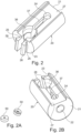
- the coupling body 20 has a cut in a direction transverse to the axis of the body that passes through it from one side to the other for a portion thereof creating a blocking jaw. More precisely, this sectional cut is provided with a slot or hole shaped widened portion 36 and a rectangular shaped elongated portion 37 that ends with a hole shaped widened portion 24. Two spaced appendages 25 having thickened free ends 26 extend axially outward from the second base 23. Moreover, the lateral surface of the coupling body 20 is provided with a recess 27 extending from the first base 21 to the second base 23 to produce a seat.
- a head adapter 50 in the form of a small washer, is arranged the purpose of which is to compensate for the space created between sharp edged attachment and rounded end of the body of the gas cylinder 18.
- a safety cap 30 is provided with a cylindrical base 31, having the same section as the coupling body 20, and an axial extension 32 complementary in shape to the shape of the recess 27 machined on the lateral surface of the coupling body 20, into which it is inserted. Its function is to close the coupling body 20 maintaining spherical ends pre-inserted in position of the attachments 14 and 15.
- the cylindrical base 31 of the safety cap 30 is provided with two shaped cavities 33 adapted to receive and block the two appendages 25, with thickened ends 26, provided on the second base 23 of the coupling body 20 in the manner of a dovetail coupling. In this way, a positioning that is secure and not freely releasable is obtained.
- the inner wall of the axial extension 32 is provided with two rounded extensions 34 and 35 housed respectively in the hole shaped widened portion 24 and in the slot or hole shaped widened portion 36 provided in the sectional cut that on the opposite side respectively house a part of spherical ends 42 and 45 of a pin 40 and of a pin 39 which belong to the two attachments 14 and 15.
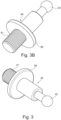
- the first attachment 14 to the side panel 16 of the furniture unit 11 comprises a linear pin 40, cylindrical in shape with a variable section.
- the linear pin 40 is provided with a threaded end 41, which is inserted by screwing into a hole of the side panel 16, and a spherical free end 42 for connection to one of the two coupling bodies 20 integral with an end of the gas cylinder 18 with related rod 13.
- An intermediate portion of the first attachment 40 is provided with a flange 38 that facilitates its stable positioning in the hole of the side panel abutting against the inner surface of the side panel.
- the second attachment 15 to the door 17 is produced in two mutually couplable parts and comprises a right angle base 43 and a right angle moving slide 44.
- the right angle base 43 is to be fixed to the wooden/frame part of the door 17 and the moving slide 44 is positioned exactly over the right angle base 43 and slidably fastened thereto.
- the moving slide 44 is provided in its vertical part with a pin 39 with spherical free end 45 made of steel for coupling to the other of the two coupling bodies 20 integral with the other end of the rod 18 of the aforesaid gas cylinder.
- the right angle base 43 to be fixed to the wooden/frame part of the door 17, has a positioning pin 46, which extends under its base side, to be inserted into a pre-hole specifically created in the wooden door 17/in the frame of the structure.
- the base side also has a countersunk hole 47 for an anti-rotation screw for fastening to the door. In this way two integral connection points are obtained between right angle base 43 and structure of the door 17.
- Two projecting milled sides 48, serving as tracks for sliding and positioning of the moving slide 44, are present on the sides of the base side of the right angle base 43.
- the moving slide 44 in turn has undercuts 49 in the lower part for slidable coupling and positioning on the two milled sides 48 of the right angle base 43.
- the function of the safety cap 30 is to close the coupling body maintaining the spherical ends 42 or 45 blocked as a result of the jaw shape of the coupling body 20.
- the hole 36 machined in the dividing cut is present in the coupling body, along the height of the cylindrical shape that produces it: the hole 36 is for housing the ball head 42 or 45 respectively of the attachment 14 or 15, while the cut that creates the division into two parts is necessary in order to adapt, bending during insertion of the pin 40 or 39, to the ball head present on the attachment 14 or 15.
- the coupling body 20 In the front part of the coupling body 20, opposite the screw attachment of the rod, the coupling body 20 also has the two aforesaid spaced appendages 25 having thickened free ends 26 for connection to the safety cap 30.
- Another interesting detail consists of the construction of the second attachment 15 in which the right angle moving slide 44 is slidable over the right angle base 43, once said right angle base 43 has been fixed to the wooden part/frame of the door 17.
- This moving slide 44 is positioned exactly over the right angle base 43 and this particular design is developed to completely conceal screws or fixing points of the right angle base.
- This system has two particular features:
- the coupling body or head is a cylinder with a diameter of 12 mm and a length of 22 mm.
- the safety cap is cylindrical in shape with a diameter of 12 mm and a height of 6 mm.
- the system must be mounted on gas springs for example having a rod with a diameter of 4 mm.
- the body of the gas springs will have a limited diameter.
- the gas springs will probably be used on furniture products such as lift-up/drop-down doors in which the front part is very often made entirely of glass or has a frame supporting a transparent surface. This means that the gas spring will remain visible even when the door is closed.
- the present invention consists in producing a coupling or attachment body for a gas spring having a rod with a diameter of 4 mm that can obtain features of safety and functionality all enclosed in a cylindrical shape with limited dimensions of around 12 mm in diameter by 30 mm in height.
- the new coupling body and the new attachments on the side panel and on the door must have clean and simple lines in perfect harmony with the body of the gas spring which cannot change in shape and dimension (dimensions dictated by the physical specifications of the spring).
- the gas spring, in compressed position, must be minimal, obviously visible but discreet and elegant.
Landscapes
- Hinges (AREA)
- Closing And Opening Devices For Wings, And Checks For Wings (AREA)
- Fluid-Damping Devices (AREA)
Applications Claiming Priority (1)
| Application Number | Priority Date | Filing Date | Title |
|---|---|---|---|
| IT102021000032108A IT202100032108A1 (it) | 2021-12-22 | 2021-12-22 | Sistema di attacco a molla a gas per una cerniera per un’anta a ribalta |
Publications (1)
| Publication Number | Publication Date |
|---|---|
| EP4202165A1 true EP4202165A1 (de) | 2023-06-28 |
Family
ID=80461257
Family Applications (1)
| Application Number | Title | Priority Date | Filing Date |
|---|---|---|---|
| EP22211313.6A Pending EP4202165A1 (de) | 2021-12-22 | 2022-12-05 | Gasfederbefestigungssystem für ein scharnier für eine auf-/abhebetür |
Country Status (2)
| Country | Link |
|---|---|
| EP (1) | EP4202165A1 (de) |
| IT (1) | IT202100032108A1 (de) |
Citations (4)
| Publication number | Priority date | Publication date | Assignee | Title |
|---|---|---|---|---|
| FR2388157A1 (fr) | 1977-04-20 | 1978-11-17 | Bensa Didier | Embout pour articulation spherique |
| US5112153A (en) * | 1990-07-17 | 1992-05-12 | Maremont Corporation | End connector assembly with ball held captive in socket bearing and shell housing and method of assembly |
| FR2739664A1 (fr) | 1995-10-09 | 1997-04-11 | Adwest Oci Sa | Embout pour element d'accouplement |
| EP2078811A2 (de) * | 2008-01-08 | 2009-07-15 | Baldacci S.p.A. | Scharniervorrichtung für Türen von Möbelteilen in Fahrzeugen, insbesondere für Wohnwagen, mobile Häuser und Boote |
-
2021
- 2021-12-22 IT IT102021000032108A patent/IT202100032108A1/it unknown
-
2022
- 2022-12-05 EP EP22211313.6A patent/EP4202165A1/de active Pending
Patent Citations (4)
| Publication number | Priority date | Publication date | Assignee | Title |
|---|---|---|---|---|
| FR2388157A1 (fr) | 1977-04-20 | 1978-11-17 | Bensa Didier | Embout pour articulation spherique |
| US5112153A (en) * | 1990-07-17 | 1992-05-12 | Maremont Corporation | End connector assembly with ball held captive in socket bearing and shell housing and method of assembly |
| FR2739664A1 (fr) | 1995-10-09 | 1997-04-11 | Adwest Oci Sa | Embout pour element d'accouplement |
| EP2078811A2 (de) * | 2008-01-08 | 2009-07-15 | Baldacci S.p.A. | Scharniervorrichtung für Türen von Möbelteilen in Fahrzeugen, insbesondere für Wohnwagen, mobile Häuser und Boote |
Also Published As
| Publication number | Publication date |
|---|---|
| IT202100032108A1 (it) | 2023-06-22 |
Similar Documents
| Publication | Publication Date | Title |
|---|---|---|
| JP6437081B2 (ja) | 固定デバイス | |
| US8727460B2 (en) | Piece of furniture and device for a piece of furniture | |
| CN108316794B (zh) | 碰珠门扣 | |
| US10865821B2 (en) | Joining device with wide accessibility for parts of furniture and furnishing items | |
| US12553460B2 (en) | Support device for furniture shelves | |
| EP2542118B1 (de) | Sperrvorrichtung zur vorübergehenden befestigung von bauelementen aneinander | |
| ES2890721T3 (es) | Brazo de dirección ajustable en su longitud | |
| HU231217B1 (hu) | Javított csuklópánt határozott megállási pozíciókkal | |
| KR101856862B1 (ko) | 브레이슬릿 용의 조절가능한 링크 | |
| DE112015003447T5 (de) | Befestigungselement, insbesondere zur Befestigung von Fahrzeugverkleidungsplatten an einem Träger | |
| US9587670B2 (en) | Fitting for an aircraft bracing device | |
| AT515304A4 (de) | Vorrichtung zur Verbindung eines Strukturelements sowie Strukturelement | |
| US12571418B2 (en) | Actuation and blocking system of a joint between a shoulder and a shelf of furniture or other furnishing items | |
| EP4202165A1 (de) | Gasfederbefestigungssystem für ein scharnier für eine auf-/abhebetür | |
| KR20180079294A (ko) | 레일 장착용 연결 조립체 | |
| US20210355976A1 (en) | Improved actuation and blocking system of a joint between a shoulder and a shelf of a piece of furniture or other furnishing items | |
| EP3034734A1 (de) | Band für eine tür oder ein fenster | |
| US20040107646A1 (en) | Fixing element for fixing a guide rail for sliding doors | |
| CN101379265A (zh) | 用于门、窗等等的铰链 | |
| DE102014115091A1 (de) | Klemmhalterung | |
| DE102016116518A1 (de) | Halteadapter für die Fixierung von Befehls- und Meldegeräten sowie Anordnung | |
| DE3438854C2 (de) | Verbindungsbeschlag von Möbelböden mit Möbelseitenwänden | |
| DE3820331C2 (de) | ||
| RU2846605C1 (ru) | Поддерживающее полку устройство для двустороннего соединения полки с панелями предмета мебели | |
| RU2840346C1 (ru) | Поддерживающее полку устройство для двустороннего соединения полки с панелями предмета мебели |
Legal Events
| Date | Code | Title | Description |
|---|---|---|---|
| PUAI | Public reference made under article 153(3) epc to a published international application that has entered the european phase |
Free format text: ORIGINAL CODE: 0009012 |
|
| STAA | Information on the status of an ep patent application or granted ep patent |
Free format text: STATUS: THE APPLICATION HAS BEEN PUBLISHED |
|
| AK | Designated contracting states |
Kind code of ref document: A1 Designated state(s): AL AT BE BG CH CY CZ DE DK EE ES FI FR GB GR HR HU IE IS IT LI LT LU LV MC ME MK MT NL NO PL PT RO RS SE SI SK SM TR |
|
| STAA | Information on the status of an ep patent application or granted ep patent |
Free format text: STATUS: REQUEST FOR EXAMINATION WAS MADE |
|
| 17P | Request for examination filed |
Effective date: 20231108 |
|
| RBV | Designated contracting states (corrected) |
Designated state(s): AL AT BE BG CH CY CZ DE DK EE ES FI FR GB GR HR HU IE IS IT LI LT LU LV MC ME MK MT NL NO PL PT RO RS SE SI SK SM TR |