EP4202177A1 - Leiter - Google Patents
Leiter Download PDFInfo
- Publication number
- EP4202177A1 EP4202177A1 EP21217569.9A EP21217569A EP4202177A1 EP 4202177 A1 EP4202177 A1 EP 4202177A1 EP 21217569 A EP21217569 A EP 21217569A EP 4202177 A1 EP4202177 A1 EP 4202177A1
- Authority
- EP
- European Patent Office
- Prior art keywords
- parts
- ladder
- constitutes
- lateral portions
- bent
- Prior art date
- Legal status (The legal status is an assumption and is not a legal conclusion. Google has not performed a legal analysis and makes no representation as to the accuracy of the status listed.)
- Granted
Links
Images




Classifications
-
- E—FIXED CONSTRUCTIONS
- E06—DOORS, WINDOWS, SHUTTERS, OR ROLLER BLINDS IN GENERAL; LADDERS
- E06C—LADDERS
- E06C1/00—Ladders in general
- E06C1/02—Ladders in general with rigid longitudinal member or members
- E06C1/04—Ladders for resting against objects, e.g. walls poles, trees
- E06C1/06—Ladders for resting against objects, e.g. walls poles, trees in one piece
-
- E—FIXED CONSTRUCTIONS
- E06—DOORS, WINDOWS, SHUTTERS, OR ROLLER BLINDS IN GENERAL; LADDERS
- E06C—LADDERS
- E06C7/00—Component parts, supporting parts, or accessories
- E06C7/08—Special construction of longitudinal members, or rungs or other treads
- E06C7/081—Rungs or other treads comprising anti-slip features
-
- E—FIXED CONSTRUCTIONS
- E06—DOORS, WINDOWS, SHUTTERS, OR ROLLER BLINDS IN GENERAL; LADDERS
- E06C—LADDERS
- E06C7/00—Component parts, supporting parts, or accessories
- E06C7/18—Devices for preventing persons from falling
- E06C7/185—Devices providing a back support to a person on the ladder, e.g. cages
Definitions
- the present patent concerns ladders, and more specifically it concerns a new ladder suited to be used also as a step irons structure, a safety cage for ladders and a ladder with safety cage.
- Ladders which are constituted by two generally parallel upright elements or rails joined by a series of parallel crosspieces called rungs.
- the ladder is arranged with the two rails along the surface to be climbed, for example with one end resting on the ground and the other end resting on a wall, and the operator can rest his/her feet alternately on the rungs one after the other to reach the desired height.
- Ladders are used, for example, for performing maintenance activities on lighting columns or streetlights or for maintenance and picking activities on fruit trees.
- step irons are fixed ladders suited to allow quick and safe access to structures and places which, due to their height, are not easy to reach.
- step irons are used to access the roof of industrial and civil buildings, the roof of sheds, terraces, vertical structures of any kind, lighting systems, underground or above ground tanks, wells and underground silos, sewage systems, underground parking spaces, machines.
- Step irons are usually arranged vertically but can also be tilted with an inclination of no less than 75 degrees.
- Step irons due precisely to their structural characteristics, pose the risk of the user falling accidentally and therefore must be provided with a protection cage.
- Said protection cage is compulsory, according to the regulations currently in force, for all ladders exceeding 2 meters in height.
- the distance between the side of the cage opposite the plane defined by the rungs and the rungs themselves cannot exceed sixty centimeters and there must be a distance of at least 15 centimeters between the rungs and the wall where they are applied or where the ladder is applied.
- the ladders and the step irons structures currently in use are constituted by single elements, rails and rungs, which are joined in a stable manner during the production stage.
- the elements constituting ladders are made of wood or metal, while step irons structures are made of metal.
- metal ladders or step irons structures are constructed using metal section bars joined together by means of fixing elements such as, for example, bolts or through a welding operation.
- ladders or step irons structures requires work for the different cutting, shaping, and joining operations, requires the purchase and use of bolts or other connection elements or the use of welding machines for joining the various parts, in addition to producing metal scraps from the metal section bars.
- tread surfaces of the rungs of ladders or step irons structures obtained from pieces of metal section bar are smooth and consequently may be slippery.
- the subject of the present patent is a new ladder or step irons structure, hereinafter referred to only as “ladder” for the sake of description simplicity, obtained from conveniently shaped and bent metal plate.
- the subject of the present patent also includes a new safety cage for ladders, obtained from a single, conveniently shaped and bent metal plate element, and a ladder with safety cage.
- the new ladder comprises a series of steps obtained from a bent metal plate element, wherein a partial cut is carried out at the level of the bent parts, so that after the bending operation an edge portion which is raised with respect to the bent part is obtained. Said raised edge serves the function of a non slip surface.
- the entire ladder can be obtained from a conveniently cut and bent element made of metal plate or metal alloy, so as to obtain both the side rails and the rungs, and to form a ladder.
- the new cage is obtained from a single, shaped and press bent metal plate element, which can be successively mounted on a step ladder of the known type or more preferably on a step ladder of the type described herein.
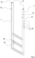
- Said element (A) comprises two lateral portions (1) which constitute the rails (1) and various central portions (2) which constitute the rungs (2).
- Each lateral portion (1) has substantially the shape of a band or strip and is formed by three parts (1a, 1b, 1c) that are parallel to one another:
- said second part (1b) is included between said first part (1a), facing towards the opposite lateral portion (1), and said third part (1c) that is diametrically opposite said opposite lateral portion (1), adheres to the same and constitutes a continuation of them.
- Said three parts (1a, 1b, 1c), which are coplanar and continuous in the element (A) obtained by cutting metal plate or a metal alloy sheet, are bent along two bending lines (v1, v2) indicated by a broken line in Figure 1 and in Figure 1a .
- Said bending lines (v1, v2) are parallel to each other and to the long side of said three parts (1a, 1b, 1c).
- said bending lines (v1, v2) may not be parallel but slightly convergent.
- each of said three parts (1a, 1b, 1c) comes to be arranged so that it is orthogonal to the adjacent part (1c, 1b, 1a) forming a linear, box-shaped element with C-shaped cross section which constitutes the lateral rail (1) of the new ladder.
- Each central portion (2) has substantially the shape of a strip and is formed by three parts (2a, 2b, 2c) parallel to one another:
- Said three parts (2a, 2b, 2c), which are coplanar and continuous in the element (A) obtained by cutting metal plate or a metal alloy element, are bent along two bending lines (o1, o2) indicated by a broken line in Figure 1a .
- Said bending lines (o1, o2) are parallel to each other and to the long side of said three parts (2a, 2b, 2c), and orthogonal to the bending lines of the three parts (1a, 1b, 1c) of the lateral portions (1).
- each of said three parts (2a, 2b, 2c) comes to be arranged so that it is orthogonal to the adjacent part (2c, 2b, 2a), forming a linear, box-shaped element with C-shaped cross section which constitutes the rung (2) of the new ladder.
- said second part (2b) of each central portion (2) constitutes the tread or foot supporting surface of the rung (2).
- cuts (2d) are such as to define further parts (2e) of said first part (2a) and third part (2c) extending towards the centre of said second part (2b).
- said further parts (2e) are facing towards said second parts (2b) and are raised with respect to it.
- each third part (2c) of the central portions (2) can be conveniently joined to said adjacent and adherent third parts (1c) of the lateral portions (1) so that the assembly made up of rungs (2) and rails (1) is sturdier and more stable.
- said sides of each third part (2c) of the central portions (2) can be joined to the third parts (1c) by means of a welding operation, rivets, or bolts or any other suitable system.
- each third part (2c) of each central portion (2) and on each third part (1c) of each lateral portion (1) there are holes (If, 2f) suited to allow the passage of said bolts or rivets and to house them, as shown in Figures 1 , 1a , 2 .
- Said lateral portions (1) are provided with further holes (1g) so that they can be joined to:
- the ends of said lateral portions (1) can be shaped (1d) or provided with seats or holes for connection to other identical shaped and bent elements (A) or to access and transit steps (5) between the ladder and the starting and landing plane of the ladder itself.
- the new ladder made up as described above, has considerable advantages.
- the new ladder has rungs (2) provided with non slip projections (2e) obtained directly by bending the metal plate.
- the new ladder is obtained from an element (A) including both the lateral rails (1) and the rungs (2).
- the new ladder is obtained from an element (A) constituted by a cut and shaped flat metal plate element.
- the new ladder does not require the assembly and/or fixing of the rungs (2) on/to the rails (1).
- the new ladder does not require the purchase and storage of different elements or parts but only of metal plate elements to be cut, shaped and bent.
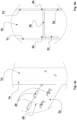
- the cage (4, 6) to be assembled on the ladder can be of the traditional type, as shown in Figure 5 , that is, made up of several shaped pieces constrained to one another, or it can be a cage of the new type, shown in Figure 6 .
- the cage (6) is formed starting from a single metal plate element, shaped and provided with openings (61), and bent in such a way as to surround said ladder completely or partially, and furthermore provided with shaped parts (62) suited to be coupled with the rails (1) of the ladder through common fixing means or other means.
Landscapes
- Engineering & Computer Science (AREA)
- Mechanical Engineering (AREA)
- Ladders (AREA)
Priority Applications (2)
| Application Number | Priority Date | Filing Date | Title |
|---|---|---|---|
| ES21217569T ES3004140T3 (en) | 2021-12-23 | 2021-12-23 | Ladder |
| EP21217569.9A EP4202177B1 (de) | 2021-12-23 | 2021-12-23 | Leiter |
Applications Claiming Priority (1)
| Application Number | Priority Date | Filing Date | Title |
|---|---|---|---|
| EP21217569.9A EP4202177B1 (de) | 2021-12-23 | 2021-12-23 | Leiter |
Publications (3)
| Publication Number | Publication Date |
|---|---|
| EP4202177A1 true EP4202177A1 (de) | 2023-06-28 |
| EP4202177C0 EP4202177C0 (de) | 2024-11-27 |
| EP4202177B1 EP4202177B1 (de) | 2024-11-27 |
Family
ID=80035172
Family Applications (1)
| Application Number | Title | Priority Date | Filing Date |
|---|---|---|---|
| EP21217569.9A Active EP4202177B1 (de) | 2021-12-23 | 2021-12-23 | Leiter |
Country Status (2)
| Country | Link |
|---|---|
| EP (1) | EP4202177B1 (de) |
| ES (1) | ES3004140T3 (de) |
Citations (4)
| Publication number | Priority date | Publication date | Assignee | Title |
|---|---|---|---|---|
| EP1036892A2 (de) * | 1999-03-13 | 2000-09-20 | Wiesbrock, Barbara | Antrittsprofil aus Metall |
| ES2226535A1 (es) * | 2002-09-20 | 2005-03-16 | Escaleras Y Objetos Practicos, S.A. | Procedimiento para la fabricacion de escaleras de mano. |
| CN110043183A (zh) * | 2019-05-17 | 2019-07-23 | 中国建筑第四工程局有限公司 | 一种桥梁圆柱墩重型安全梯笼的连墙装置 |
| CN210013648U (zh) * | 2019-03-05 | 2020-02-04 | 星光农机股份有限公司 | 一种单板成型简易踏梯 |
Family Cites Families (1)
| Publication number | Priority date | Publication date | Assignee | Title |
|---|---|---|---|---|
| IT202000015835A1 (it) * | 2020-07-01 | 2022-01-01 | Rizzotto Srl | Scala a pioli |
-
2021
- 2021-12-23 EP EP21217569.9A patent/EP4202177B1/de active Active
- 2021-12-23 ES ES21217569T patent/ES3004140T3/es active Active
Patent Citations (4)
| Publication number | Priority date | Publication date | Assignee | Title |
|---|---|---|---|---|
| EP1036892A2 (de) * | 1999-03-13 | 2000-09-20 | Wiesbrock, Barbara | Antrittsprofil aus Metall |
| ES2226535A1 (es) * | 2002-09-20 | 2005-03-16 | Escaleras Y Objetos Practicos, S.A. | Procedimiento para la fabricacion de escaleras de mano. |
| CN210013648U (zh) * | 2019-03-05 | 2020-02-04 | 星光农机股份有限公司 | 一种单板成型简易踏梯 |
| CN110043183A (zh) * | 2019-05-17 | 2019-07-23 | 中国建筑第四工程局有限公司 | 一种桥梁圆柱墩重型安全梯笼的连墙装置 |
Also Published As
| Publication number | Publication date |
|---|---|
| EP4202177C0 (de) | 2024-11-27 |
| EP4202177B1 (de) | 2024-11-27 |
| ES3004140T3 (en) | 2025-03-11 |
Similar Documents
| Publication | Publication Date | Title |
|---|---|---|
| US3853203A (en) | Independent toeboard construction | |
| CA1085778A (en) | Shelving structure | |
| EP2567033A1 (de) | Gebäudestruktur | |
| EP0204281A2 (de) | Tragestruktur für einen erhöhten Doppelboden | |
| US6745871B2 (en) | Interlocking scaffold plank | |
| EP4202177B1 (de) | Leiter | |
| US20080277200A1 (en) | Cover insert | |
| EP1840297A2 (de) | Abdeckungseinsatz | |
| US2372003A (en) | Sectional ladder | |
| EP0110849A1 (de) | Eine Oberfläche bildende Platte | |
| EP2698486B1 (de) | Vertikale Stützstruktur für Dachschutzzaun-System | |
| JP2013122156A (ja) | 傾斜屋根上における足場装置 | |
| JP2020200639A (ja) | 枠組足場用の連結ピン及び枠組足場の巾木取付構造 | |
| KR20200114593A (ko) | 이동식 틀 비계용 알루미늄 프로파일 및 이를 이용한 이동식 틀비계 | |
| US4858724A (en) | Safety fence for scaffolds | |
| KR102338929B1 (ko) | 비계용 수직사다리 | |
| IT202000015835A1 (it) | Scala a pioli | |
| EP1246977A1 (de) | Modulare verbindung für industrielle metalstrukturen | |
| US20130192927A1 (en) | Scaffolding System | |
| KR920004954Y1 (ko) | 적층 절첩식 비계 | |
| US12546104B2 (en) | Modular balcony system, components thereof and method of assembly and installation thereof | |
| EP3553251B1 (de) | Anordnung sowie tragestruktur und profil für solch eine anordnung | |
| JP2821666B2 (ja) | 梯子用横桟 | |
| JP7316122B2 (ja) | 作業足場板 | |
| CA1085777A (en) | Shelving structure |
Legal Events
| Date | Code | Title | Description |
|---|---|---|---|
| PUAI | Public reference made under article 153(3) epc to a published international application that has entered the european phase |
Free format text: ORIGINAL CODE: 0009012 |
|
| STAA | Information on the status of an ep patent application or granted ep patent |
Free format text: STATUS: THE APPLICATION HAS BEEN PUBLISHED |
|
| AK | Designated contracting states |
Kind code of ref document: A1 Designated state(s): AL AT BE BG CH CY CZ DE DK EE ES FI FR GB GR HR HU IE IS IT LI LT LU LV MC MK MT NL NO PL PT RO RS SE SI SK SM TR |
|
| STAA | Information on the status of an ep patent application or granted ep patent |
Free format text: STATUS: REQUEST FOR EXAMINATION WAS MADE |
|
| 17P | Request for examination filed |
Effective date: 20231205 |
|
| RBV | Designated contracting states (corrected) |
Designated state(s): AL AT BE BG CH CY CZ DE DK EE ES FI FR GB GR HR HU IE IS IT LI LT LU LV MC MK MT NL NO PL PT RO RS SE SI SK SM TR |
|
| STAA | Information on the status of an ep patent application or granted ep patent |
Free format text: STATUS: EXAMINATION IS IN PROGRESS |
|
| 17Q | First examination report despatched |
Effective date: 20240129 |
|
| GRAP | Despatch of communication of intention to grant a patent |
Free format text: ORIGINAL CODE: EPIDOSNIGR1 |
|
| STAA | Information on the status of an ep patent application or granted ep patent |
Free format text: STATUS: GRANT OF PATENT IS INTENDED |
|
| GRAS | Grant fee paid |
Free format text: ORIGINAL CODE: EPIDOSNIGR3 |
|
| GRAA | (expected) grant |
Free format text: ORIGINAL CODE: 0009210 |
|
| STAA | Information on the status of an ep patent application or granted ep patent |
Free format text: STATUS: THE PATENT HAS BEEN GRANTED |
|
| INTG | Intention to grant announced |
Effective date: 20240926 |
|
| AK | Designated contracting states |
Kind code of ref document: B1 Designated state(s): AL AT BE BG CH CY CZ DE DK EE ES FI FR GB GR HR HU IE IS IT LI LT LU LV MC MK MT NL NO PL PT RO RS SE SI SK SM TR |
|
| REG | Reference to a national code |
Ref country code: GB Ref legal event code: FG4D |
|
| REG | Reference to a national code |
Ref country code: CH Ref legal event code: EP |
|
| REG | Reference to a national code |
Ref country code: IE Ref legal event code: FG4D |
|
| REG | Reference to a national code |
Ref country code: DE Ref legal event code: R096 Ref document number: 602021022363 Country of ref document: DE |
|
| U01 | Request for unitary effect filed |
Effective date: 20241128 |
|
| U07 | Unitary effect registered |
Designated state(s): AT BE BG DE DK EE FI FR IT LT LU LV MT NL PT RO SE SI Effective date: 20241209 |
|
| U20 | Renewal fee for the european patent with unitary effect paid |
Year of fee payment: 4 Effective date: 20241213 |
|
| REG | Reference to a national code |
Ref country code: ES Ref legal event code: FG2A Ref document number: 3004140 Country of ref document: ES Kind code of ref document: T3 Effective date: 20250311 |
|
| PG25 | Lapsed in a contracting state [announced via postgrant information from national office to epo] |
Ref country code: IS Free format text: LAPSE BECAUSE OF FAILURE TO SUBMIT A TRANSLATION OF THE DESCRIPTION OR TO PAY THE FEE WITHIN THE PRESCRIBED TIME-LIMIT Effective date: 20250327 Ref country code: HR Free format text: LAPSE BECAUSE OF FAILURE TO SUBMIT A TRANSLATION OF THE DESCRIPTION OR TO PAY THE FEE WITHIN THE PRESCRIBED TIME-LIMIT Effective date: 20241127 |
|
| PG25 | Lapsed in a contracting state [announced via postgrant information from national office to epo] |
Ref country code: NO Free format text: LAPSE BECAUSE OF FAILURE TO SUBMIT A TRANSLATION OF THE DESCRIPTION OR TO PAY THE FEE WITHIN THE PRESCRIBED TIME-LIMIT Effective date: 20250227 |
|
| PG25 | Lapsed in a contracting state [announced via postgrant information from national office to epo] |
Ref country code: GR Free format text: LAPSE BECAUSE OF FAILURE TO SUBMIT A TRANSLATION OF THE DESCRIPTION OR TO PAY THE FEE WITHIN THE PRESCRIBED TIME-LIMIT Effective date: 20250228 |
|
| PG25 | Lapsed in a contracting state [announced via postgrant information from national office to epo] |
Ref country code: PL Free format text: LAPSE BECAUSE OF FAILURE TO SUBMIT A TRANSLATION OF THE DESCRIPTION OR TO PAY THE FEE WITHIN THE PRESCRIBED TIME-LIMIT Effective date: 20241127 |
|
| PG25 | Lapsed in a contracting state [announced via postgrant information from national office to epo] |
Ref country code: RS Free format text: LAPSE BECAUSE OF FAILURE TO SUBMIT A TRANSLATION OF THE DESCRIPTION OR TO PAY THE FEE WITHIN THE PRESCRIBED TIME-LIMIT Effective date: 20250227 |
|
| PG25 | Lapsed in a contracting state [announced via postgrant information from national office to epo] |
Ref country code: SM Free format text: LAPSE BECAUSE OF FAILURE TO SUBMIT A TRANSLATION OF THE DESCRIPTION OR TO PAY THE FEE WITHIN THE PRESCRIBED TIME-LIMIT Effective date: 20241127 |
|
| PG25 | Lapsed in a contracting state [announced via postgrant information from national office to epo] |
Ref country code: SK Free format text: LAPSE BECAUSE OF FAILURE TO SUBMIT A TRANSLATION OF THE DESCRIPTION OR TO PAY THE FEE WITHIN THE PRESCRIBED TIME-LIMIT Effective date: 20241127 |
|
| PG25 | Lapsed in a contracting state [announced via postgrant information from national office to epo] |
Ref country code: CZ Free format text: LAPSE BECAUSE OF FAILURE TO SUBMIT A TRANSLATION OF THE DESCRIPTION OR TO PAY THE FEE WITHIN THE PRESCRIBED TIME-LIMIT Effective date: 20241127 |
|
| PG25 | Lapsed in a contracting state [announced via postgrant information from national office to epo] |
Ref country code: MC Free format text: LAPSE BECAUSE OF FAILURE TO SUBMIT A TRANSLATION OF THE DESCRIPTION OR TO PAY THE FEE WITHIN THE PRESCRIBED TIME-LIMIT Effective date: 20241127 |
|
| PLBE | No opposition filed within time limit |
Free format text: ORIGINAL CODE: 0009261 |
|
| STAA | Information on the status of an ep patent application or granted ep patent |
Free format text: STATUS: NO OPPOSITION FILED WITHIN TIME LIMIT |
|
| REG | Reference to a national code |
Ref country code: CH Ref legal event code: L10 Free format text: ST27 STATUS EVENT CODE: U-0-0-L10-L00 (AS PROVIDED BY THE NATIONAL OFFICE) Effective date: 20251008 |
|
| PG25 | Lapsed in a contracting state [announced via postgrant information from national office to epo] |
Ref country code: IE Free format text: LAPSE BECAUSE OF NON-PAYMENT OF DUE FEES Effective date: 20241223 |
|
| 26N | No opposition filed |
Effective date: 20250828 |
|
| REG | Reference to a national code |
Ref country code: CH Ref legal event code: U11 Free format text: ST27 STATUS EVENT CODE: U-0-0-U10-U11 (AS PROVIDED BY THE NATIONAL OFFICE) Effective date: 20260101 |
|
| PGFP | Annual fee paid to national office [announced via postgrant information from national office to epo] |
Ref country code: GB Payment date: 20251229 Year of fee payment: 5 |
|
| U20 | Renewal fee for the european patent with unitary effect paid |
Year of fee payment: 5 Effective date: 20251229 |
|
| PGFP | Annual fee paid to national office [announced via postgrant information from national office to epo] |
Ref country code: ES Payment date: 20260102 Year of fee payment: 5 |
|
| PGFP | Annual fee paid to national office [announced via postgrant information from national office to epo] |
Ref country code: CH Payment date: 20260101 Year of fee payment: 5 |
|
| PG25 | Lapsed in a contracting state [announced via postgrant information from national office to epo] |
Ref country code: CY Free format text: LAPSE BECAUSE OF FAILURE TO SUBMIT A TRANSLATION OF THE DESCRIPTION OR TO PAY THE FEE WITHIN THE PRESCRIBED TIME-LIMIT Effective date: 20241127 |