EP4202191B1 - Rückhaltestecker - Google Patents
Rückhaltestecker Download PDFInfo
- Publication number
- EP4202191B1 EP4202191B1 EP22215211.8A EP22215211A EP4202191B1 EP 4202191 B1 EP4202191 B1 EP 4202191B1 EP 22215211 A EP22215211 A EP 22215211A EP 4202191 B1 EP4202191 B1 EP 4202191B1
- Authority
- EP
- European Patent Office
- Prior art keywords
- arm
- sheath
- passage
- slider seal
- plug assembly
- Prior art date
- Legal status (The legal status is an assumption and is not a legal conclusion. Google has not performed a legal analysis and makes no representation as to the accuracy of the status listed.)
- Active
Links
Images


Classifications
-
- F—MECHANICAL ENGINEERING; LIGHTING; HEATING; WEAPONS; BLASTING
- F01—MACHINES OR ENGINES IN GENERAL; ENGINE PLANTS IN GENERAL; STEAM ENGINES
- F01D—NON-POSITIVE DISPLACEMENT MACHINES OR ENGINES, e.g. STEAM TURBINES
- F01D21/00—Shutting-down of machines or engines, e.g. in emergency; Regulating, controlling, or safety means not otherwise provided for
- F01D21/003—Arrangements for testing or measuring
-
- F—MECHANICAL ENGINEERING; LIGHTING; HEATING; WEAPONS; BLASTING
- F01—MACHINES OR ENGINES IN GENERAL; ENGINE PLANTS IN GENERAL; STEAM ENGINES
- F01D—NON-POSITIVE DISPLACEMENT MACHINES OR ENGINES, e.g. STEAM TURBINES
- F01D25/00—Component parts, details, or accessories, not provided for in, or of interest apart from, other groups
- F01D25/24—Casings; Casing parts, e.g. diaphragms, casing fastenings
-
- F—MECHANICAL ENGINEERING; LIGHTING; HEATING; WEAPONS; BLASTING
- F01—MACHINES OR ENGINES IN GENERAL; ENGINE PLANTS IN GENERAL; STEAM ENGINES
- F01D—NON-POSITIVE DISPLACEMENT MACHINES OR ENGINES, e.g. STEAM TURBINES
- F01D9/00—Stators
- F01D9/06—Fluid supply conduits to nozzles or the like
- F01D9/065—Fluid supply or removal conduits traversing the working fluid flow, e.g. for lubrication-, cooling-, or sealing fluids
-
- F—MECHANICAL ENGINEERING; LIGHTING; HEATING; WEAPONS; BLASTING
- F05—INDEXING SCHEMES RELATING TO ENGINES OR PUMPS IN VARIOUS SUBCLASSES OF CLASSES F01-F04
- F05D—INDEXING SCHEME FOR ASPECTS RELATING TO NON-POSITIVE-DISPLACEMENT MACHINES OR ENGINES, GAS-TURBINES OR JET-PROPULSION PLANTS
- F05D2230/00—Manufacture
- F05D2230/72—Maintenance
-
- F—MECHANICAL ENGINEERING; LIGHTING; HEATING; WEAPONS; BLASTING
- F05—INDEXING SCHEMES RELATING TO ENGINES OR PUMPS IN VARIOUS SUBCLASSES OF CLASSES F01-F04
- F05D—INDEXING SCHEME FOR ASPECTS RELATING TO NON-POSITIVE-DISPLACEMENT MACHINES OR ENGINES, GAS-TURBINES OR JET-PROPULSION PLANTS
- F05D2240/00—Components
- F05D2240/10—Stators
- F05D2240/14—Casings or housings protecting or supporting assemblies within
-
- F—MECHANICAL ENGINEERING; LIGHTING; HEATING; WEAPONS; BLASTING
- F05—INDEXING SCHEMES RELATING TO ENGINES OR PUMPS IN VARIOUS SUBCLASSES OF CLASSES F01-F04
- F05D—INDEXING SCHEME FOR ASPECTS RELATING TO NON-POSITIVE-DISPLACEMENT MACHINES OR ENGINES, GAS-TURBINES OR JET-PROPULSION PLANTS
- F05D2240/00—Components
- F05D2240/55—Seals
-
- F—MECHANICAL ENGINEERING; LIGHTING; HEATING; WEAPONS; BLASTING
- F05—INDEXING SCHEMES RELATING TO ENGINES OR PUMPS IN VARIOUS SUBCLASSES OF CLASSES F01-F04
- F05D—INDEXING SCHEME FOR ASPECTS RELATING TO NON-POSITIVE-DISPLACEMENT MACHINES OR ENGINES, GAS-TURBINES OR JET-PROPULSION PLANTS
- F05D2260/00—Function
- F05D2260/30—Retaining components in desired mutual position
- F05D2260/31—Retaining bolts or nuts
-
- F—MECHANICAL ENGINEERING; LIGHTING; HEATING; WEAPONS; BLASTING
- F05—INDEXING SCHEMES RELATING TO ENGINES OR PUMPS IN VARIOUS SUBCLASSES OF CLASSES F01-F04
- F05D—INDEXING SCHEME FOR ASPECTS RELATING TO NON-POSITIVE-DISPLACEMENT MACHINES OR ENGINES, GAS-TURBINES OR JET-PROPULSION PLANTS
- F05D2260/00—Function
- F05D2260/30—Retaining components in desired mutual position
- F05D2260/38—Retaining components in desired mutual position by a spring, i.e. spring loaded or biased towards a certain position
-
- F—MECHANICAL ENGINEERING; LIGHTING; HEATING; WEAPONS; BLASTING
- F05—INDEXING SCHEMES RELATING TO ENGINES OR PUMPS IN VARIOUS SUBCLASSES OF CLASSES F01-F04
- F05D—INDEXING SCHEME FOR ASPECTS RELATING TO NON-POSITIVE-DISPLACEMENT MACHINES OR ENGINES, GAS-TURBINES OR JET-PROPULSION PLANTS
- F05D2260/00—Function
- F05D2260/80—Diagnostics
Definitions
- the subject matter disclosed herein relates generally to gas turbine engines and, more particularly, the present invention relates to a method and tea plug for plugging an inspection port in a gas turbine engine
- US 6 468 033 B1 discloses a borescope plug assembly comprising a plunger, a biasing mechanism and a retainer.
- Gas turbine engines typically operate at high rotational speeds and high temperatures for increased performance and efficiency.
- performance of an engine may be tied to proper operation and function of engine components.
- components may be damaged, fail or otherwise require maintenance.
- control of an engine may be based on the operation of components within an engine.
- Safety inspections and routine maintenance are often required to ensure safe operation and prevent engine failure.
- Many gas turbine engines include inspection ports to allow for inspection and/or maintenance of an engine. Conventional methods of sealing these ports are can be expensive and in some cases, may lead to foreign object damage (FOD) due to improper installation during manufacture or maintenance.
- FOD foreign object damage
- some gas turbine engines may have dozens of ports.
- correct operation and installation of port components may be required for safe and efficient operation of an engine. There is a need in the art for port components for gas turbine engines.
- a method for assembling a plug assembly for plugging one or more ports of a gas turbine engine includes that a first arm is inserted into a sheath through-passage of a sheath.
- the first arm including a first longitudinal portion and a first projection portion.
- the method also includes the first projection portion is inserted through a first opening in a passageway portion of the sheath.
- the method includes a second arm is inserted into the sheath through-passage of the sheath.
- the second arm including a second longitudinal portion and a second projection portion.
- the method further includes the second projection portion is inserted through a second opening in the passageway portion of the sheath, a separating mechanism is inserted into the sheath through-passage between the first arm and the second arm, a biasing mechanism is installed, and a top housing is slid over the biasing mechanism such that the biasing mechanism is located in a cavity defined within the top housing.
- the biasing mechanism being configured to apply a force to the first arm and the second arm when the biasing mechanism is located in the cavity.
- the method may also include that the top housing is secured together with the sheath.
- further embodiments may include a slider seal housing is secured onto a radially outward surface of an inner casing of the gas turbine and a slider seal is inserted into the slider seal housing, the slider seal housing including a slider seal seat configured to fit the slider seal therein.
- the method may also include that a slider seal cover is secured to the slider seal housing. The slider seal cover being configured to secure the slider seal in the slider seal housing.
- the inner casing further includes an inner port.
- the slider seal housing further includes a slider seal housing through-passage aligned with the inner port.
- the slider seal further includes a seal through-passage aligned with the inner port.
- the slider seal cover further includes a cover through-passage aligned with the inner port.
- the method further includes that an inner end of the sheath is inserted through the cover through-passage, the seal through-passage, and the slider seal housing through-passage.
- the method further includes that the inner end of the sheath is inserted into the inner port of the inner casing of the gas turbine engine.
- further embodiments may include that an inner end of the sheath is inserted into an inner port of an inner casing of the gas turbine engine.
- further embodiments may include that the plug assembly is secured to the gas turbine engine.
- further embodiments may include that the plug assembly is secured to an outer casing of the gas turbine engine.
- further embodiments may include that the plug assembly is secured to the gas turbine engine by aligning a housing through-passage within the top housing and a flange through-passage within a flange portion of the sheath with a threaded hole in the outer casing or in a component attached to the outer casing, inserting a fastening mechanism through the housing through-passage and through the flange through-passage, and rotating the fastening mechanism such that a threaded portion of the fastening mechanism interlocks with the threaded hole to secure the plug assembly to the gas turbine engine.
- the separating mechanism is a separator body.
- the separator body includes a lower end, an upper end located opposite the lower end, and a separator body flange located between the lower end and the upper end.
- the separator body flange dividing the separator body into a lower portion located at or proximate the lower end and an upper portion located at or proximate the upper end.
- further embodiments may include that the lower end is pointed or wedge shaped.
- further embodiments may include that the biasing mechanism is installed by sliding the biasing mechanism onto the upper portion of the separator body.
- further embodiments may include that a c-seal is placed on the first arm and the second arm.
- further embodiments may include that the separating mechanism is a spring.
- further embodiments may include that the biasing mechanism is a spring.
- further embodiments may include that the separating mechanism is a wedge shaped body.
- the first longitudinal portion and the second longitudinal portion have a wedge shape.
- further embodiments may include that the separating mechanism is a connector arm connecting the first arm to the second arm.
- a plug assembly for plugging one or more ports of a gas turbine engine includes a sheath that includes an inner end, an outer end located opposite the inner end, a passageway portion located at or proximate the inner end, a sheath through-passage extending from the outer end to a sheath through-passage base proximate the inner end, a first opening in the passageway portion, and a second opening in the passageway portion.
- the plug assembly also includes a first arm that includes a first longitudinal portion located in the sheath through-passage and a first projection portion projecting through the first opening.
- the plug assembly further includes a second arm including a second longitudinal portion located in the sheath through-passage and a second projection portion projecting through the second opening.
- the plug assembly yet further includes a separating mechanism located in the sheath through-passage between the first arm and the second arm. The separating mechanism configured to separate the first arm from the second arm.
- the plug assembly also includes a biasing mechanism configured to apply a force to the first arm and the second arm. The force is parallel to the first longitudinal portion and the second longitudinal portion.
- the plug assembly further includes a top housing abutting the outer end of the sheath. The top housing including a cavity formed therein. The biasing mechanism is located in the cavity.
- further embodiments may include that the separating mechanism is a separator body and the separator body includes a lower end, an upper end located opposite the lower end, and a separator body flange located between the lower end and the upper end.
- the separator body flange dividing the separator body into a lower portion located at or proximate the lower end and an upper portion located at or proximate the upper end.
- further embodiments may include that the lower end is pointed or wedge shaped to help drive the first arm and the second arm apart.
- further embodiments may include that the biasing mechanism is located on the upper portion of the separator body.
- further embodiments may include that the separating mechanism is a spring.
- FIG. 1 schematically illustrates a gas turbine engine 20.
- the gas turbine engine 20 is disclosed herein as a two-spool turbofan that generally incorporates a fan section 22, a compressor section 24, a combustor section 26, and a turbine section 28.
- the fan section 22 drives air along a bypass flow path B in a bypass duct, while the compressor section 24 drives air along a core flow path C for compression and communication into the combustor section 26 then expansion through the turbine section 28.
- FIG. 1 schematically illustrates a gas turbine engine 20.
- the gas turbine engine 20 is disclosed herein as a two-spool turbofan that generally incorporates a fan section 22, a compressor section 24, a combustor section 26, and a turbine section 28.
- the fan section 22 drives air along a bypass flow path B in a bypass duct
- the compressor section 24 drives air along a core flow path C for compression and communication into the combustor section 26 then expansion through the turbine section 28.
- the exemplary engine 20 generally includes a low speed spool 30 and a high speed spool 32 mounted for rotation about an engine central longitudinal axis A relative to an engine static structure 36 via several bearing systems 38. It should be understood that various bearing systems 38 at various locations may alternatively or additionally be provided, and the location of bearing systems 38 may be varied as appropriate to the application.
- the low speed spool 30 generally includes an inner shaft 40 that interconnects a fan 42, a low pressure compressor 44 and a low pressure turbine 46.
- the inner shaft 40 is connected to the fan 42 through a speed change mechanism, which in exemplary gas turbine engine 20 is illustrated as a geared architecture 48 to drive the fan 42 at a lower speed than the low speed spool 30.
- the high speed spool 32 includes an outer shaft 50 that interconnects a high pressure compressor 52 and high pressure turbine 54.
- a combustor 56 is arranged in exemplary gas turbine 20 between the high pressure compressor 52 and the high pressure turbine 54.
- An engine static structure 36 is arranged generally between the high pressure turbine 54 and the low pressure turbine 46.
- the engine static structure 36 further supports bearing systems 38 in the turbine section 28.
- the inner shaft 40 and the outer shaft 50 are concentric and rotate via bearing systems 38 about the engine central longitudinal axis A which is collinear with their longitudinal axes.
- stator vanes 45 in the low pressure compressor 44 and stator vanes 55 in the high pressure compressor 52 may be adjustable during operation of the gas turbine engine 20 to support various operating conditions. In other embodiments, the stator vanes 45, 55 may be held in a fixed position.
- the turbines 46, 54 rotationally drive the respective low speed spool 30 and high speed spool 32 in response to the expansion. It will be appreciated that each of the positions of the fan section 22, compressor section 24, combustor section 26, turbine section 28, and fan drive gear system 48 may be varied. For example, gear system 48 may be located aft of combustor section 26 or even aft of turbine section 28, and fan section 22 may be positioned forward or aft of the location of gear system 48.
- the engine 20 in one example is a high-bypass geared aircraft engine.
- the engine 20 bypass ratio is greater than about six (6), with an example embodiment being greater than about ten (10)
- the geared architecture 48 is an epicyclic gear train, such as a planetary gear system or other gear system, with a gear reduction ratio of greater than about 2.3
- the low pressure turbine 46 has a pressure ratio that is greater than about five.
- the engine 20 bypass ratio is greater than about ten (10:1)
- the fan diameter is significantly larger than that of the low pressure compressor 44
- the low pressure turbine 46 has a pressure ratio that is greater than about five 5:1.
- Low pressure turbine 46 pressure ratio is pressure measured prior to inlet of low pressure turbine 46 as related to the pressure at the outlet of the low pressure turbine 46 prior to an exhaust nozzle.
- the geared architecture 48 may be an epicycle gear train, such as a planetary gear system or other gear system, with a gear reduction ratio of greater than about 2.3:1. It should be understood, however, that the above parameters are only exemplary of one embodiment of a geared architecture engine and that the present disclosure is applicable to other gas turbine engines including direct drive turbofans.
- the fan section 22 of the engine 20 is designed for a particular flight condition--typically cruise at about 0.8Mach and about 35,000 feet (10,688 meters).
- 'TSFC' Thrust Specific Fuel Consumption
- Low fan pressure ratio is the pressure ratio across the fan blade alone, without a Fan Exit Guide Vane (“FEGV”) system.
- the low fan pressure ratio as disclosed herein according to one non-limiting embodiment is less than about 1.45.
- Low corrected fan tip speed is the actual fan tip speed in ft/sec divided by an industry standard temperature correction of [(Tram °R)/(518.7 °R)] 0.5 .
- the "Low corrected fan tip speed” as disclosed herein according to one non-limiting embodiment is less than about 1150 ft/second (350.5 m/sec).
- FIGS. 2 and 3 a graphical representation of a plug assembly 100 (see also FIGS. 3-10) located within a gas turbine engine 20 is illustrated, in accordance with an embodiment of the present disclosure.
- the plug assembly 100 may be a borescope plug assembly and inspection port assembly.
- the plug assembly 100 are shown within an outer port 62 located within an outer casing 60 of the gas turbine engine 20 and an inner port 66 located in an inner casing 64 of the gas turbine engine 20.
- the outer port 62 may be a borescope port or an inspection port.
- the outer casing 60 may be a high pressure turbine case.
- the outer casing 60 may also be a lower pressure turbine case, a diffuser case, a high pressure compressor case, or any other case that requires an in section port in the gas turbine engine 20.
- the plug assembly 100 extend radially inward toward the engine central longitudinal axis A of the gas turbine engine 20. As illustrated in FIG. 2 , the plug assembly 100 may extend from the inner port 66 to the outer port 62.
- the inner casing 64 is located radially inward from the outer casing 60.
- the inner casing 64 may be a mid-turbine frame (MTF) vane casing. It is understood that the inner casing 64 is not limited to the MTF vane casing and the embodiment described herein are applicable to the inner casing 64 being any other casing or component located within the gas turbine engine 20 that is radially inward from the outer casing 60.
- MTF mid-turbine frame
- the inner casing 64 includes a radially inward surface 67 and a radially outward surface 65 located opposite the radially inward surface 67.
- the radially outward surface 65 is located radially outward of the radially inward surface 67.
- the inner port 66 extends from the radially inward surface 67 to the radially outward surface 65.
- the inner port 66 and the outer port 62 may be located in the turbine section 28 of the gas turbine engine 20. It is understood that the embodiments disclosed herein are not limited to the inner port 66 and the outer port 62 being located in the turbine section 28 of the gas turbine engine 20, and therefore the inner port 66 and the outer port 62 may be located in other sections of the gas turbine engine.
- the turbine section 28 is located aft of the combustor section 26.
- the turbine section 28 includes a plurality of vanes 68 extending circumferentially around the engine central longitudinal axis A.
- the inner port 66 and the outer port 62 may be located interposed circumferentially between two adjacent vanes 68, as illustrated in FIG. 3 .
- the plug assembly 100 may allow inspection into the outer port 62 and inner port 66.
- the plug assembly 100 provides access to the gas turbine engine 20 radially inward of the outer port 62 and/or the inner port 66 for mechanical diagnostics or other diagnostic reasons.
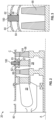
- FIG. 4 a cross-sectional view of a plug assembly 100 is illustrated, in accordance with an embodiment of the present disclosure.
- the plug assembly 100 may be configured to secure an outer casing 60 in place, a slider seal housing 110 in place, a slider seal 120 in place, a slider seal cover 130 in place, or any other component of the gas turbine engine 20 in place. Further it is understood that while the plug assembly 100 has been described herein as securing the slider seal cover 130 in place, the plug assembly 100 may secure any component of the gas turbine engine 20 in place.
- the plug assembly 100 of FIG. 4 may include the slider seal housing 110, the slider seal 120, the slider seal cover 130, a sheath 140, a first arm 150a, a second arm 150b, a separator body 160, a c-seal 170, a top housing 180, one or more fastening mechanism 190, and a biasing mechanism 192.
- the slider seal housing 110 abuts the radially outward surface 65 of the inner casing 64.
- the slider seal housing 110 may be secured to the radially outward surface 65 of the inner casing 64.
- the slider seal housing 110 may be secured to the radially outward surface 65 of the inner casing 64 via a weld or any other attachment method know to one of skill in the art.
- the slider seal housing 110 includes a slider seal seat 112 configured to fit the slider seal 120 therein.
- the slider seal 120 is configured to fit within the slider seal seat 112.
- the slider seal 120 is secured within the slider seal seat 112 by a slider seal cover 130.
- the slider seal cover 130 is secured to the slider seal housing 110.
- the slider seal cover 130 may be secured to the slider seal housing 110 via a weld or any other attachment method know to one of skill in the art.
- the slider seal cover 130 is configured to maintain or entrap the slider seal 120 within the slider seal housing 110 such that the slider seal 120 is free to slide between the slider seal cover 130 and slider seal housing 110 and is not fixed in place.
- the slider seal cover 130 may be configured to allow the slider seal 120 to move freely relative to the slider seal cover 130 and the slider seal housing 110.
- the slider seal housing 110 may be circular in shape with a slider seal housing through-passage 114.
- the slider seal 120 may be circular in shape with a seal through-passage 124.
- the slider seal cover 130 may be circular in shape with a cover through-passage 134.
- the sheath 140 is configured to pass through the slider seal housing through-passage 114, the seal through-passage 124, and the cover through passage 134 to plug the inner port 66.
- the sheath 140 includes an inner end 142 and outer end 144 located radially outward from the inner end 142 when the plug assembly 100 is installed in the gas turbine engine 20.
- the inner end 142 of the sheath 140 is configured to plug the inner port 66 and the outer end 144 of the sheath 140 abuts the top housing 180.
- the sheath 140 includes a passageway portion 146 and a flange portion 148.
- the passageway portion 146 is located at or proximate the inner end 142 and the flange portion 148 is located at or proximate the outer end 144.
- a sheath through-passage 141 extends through the sheath 140 from the outer end 144 to a sheath through-passage base 143 proximate the inner end 142.
- the sheath through-passage 141 is a blind hole as it does not pass completely through the inner end 142.
- the top housing 180 includes a top end 184 and a bottom end 182 located opposite the top end 184.
- the bottom end 182 of the top housing 180 abuts the inner end 142 of the sheath 140.
- the top housing 180 includes a cavity 186 extending from the bottom end 182 of the top housing 180 into the top housing 180 to a base 188.
- the cavity 186 is a blind hole as it does not pass completely through the top housing 180.
- the cavity 186 is configured to align with the sheath through-passage 141.
- the separator body 160 is located within the combined cavity defined by the cavity 186 and the sheath through-passage 141. Thus, the separator body 160 extends across the cavity 186 and the sheath through-passage 141.
- the separator body 160 includes a lower end 162 and an upper end 164 located opposite the lower end 162.
- the upper end 164 is located proximate the base 188 of the cavity 186 in the top housing 180.
- the lower end 162 may be pointed or wedge shaped to help drive the arms 150 apart during installation, as discussed further herein.
- the separator body 160 includes a separator body flange 166 located between the upper end 164 and the lower end 162.
- the separator body flange 166 includes an upper surface 165 and a lower surface 167 located opposite the upper surface 165.
- the separator body flange 166 divides or separates the separator body flange 166 into an upper portion 161 and a lower portion 163.
- the upper portion 161 is located at or proximate the upper end 164 and the lower portion 163 is located at or proximate the lower end 162.
- the biasing mechanism 192 is interposed between the base 188 of the cavity 186 and the upper surface 165 of the separator body flange 166.
- the biasing mechanism 192 may be a spring.
- the biasing mechanism 192 applies a force against the base 188 and the upper surface 165 and pushes the upper surface 165 and the separator body 160 radially inward towards the inner port 66, which applies a radially inward force to the first arm 150a and the second arm 150b, which applies a force to maintain the slider seal cover 130 in place in the event welds were to fail between the slider seal cover 130 and the slider seal housing 110 or between the slider seal housing 110 and the inner casing 64.
- the c-seal 170 may be located interposed between the lower surface 167 and the first arm 150a and the second arm 150b as illustrated in FIG. 4 .
- the first arm 150a includes a first longitudinal portion 152a and a first projection portion 154a.
- the first projection portion 154a may be oriented at about a right angle (e.g., 90 degrees) to the first longitudinal portion 152a.
- the first projection portion 154a applies the aforementioned force to the slider seal cover 130.
- the second arm 150b includes a second longitudinal portion 152b and a second projection portion 154b.
- the second projection portion 154b may be oriented at about a right angle (e.g., 90 degrees) to the second longitudinal portion 152b.
- the second projection portion 154b applies the aforementioned force to the slider seal cover 130.
- the plug assembly 100 of FIG. 4 uses the separator body 160 as a separating mechanism to push the first arm 150a and the second arm 150b apart.
- the separator body 160 may help drive and/or maintain the first projection portion 154a through a first opening 147 in a passageway portion 146 of the sheath 140 and the second projection portion 154b through a second opening 149 in the passageway portion 146 of the sheath 140.
- the first opening 147 and the second opening 149 may be oriented about perpendicular with the sheath through-passage 141 of the sheath 140
- the plug assembly 100 further includes one or more fastening mechanism 190 configured to secure the top housing 180 together with the sheath 140. More specifically, the fastening mechanism 190 secures the top housing 180 to the flange portion 148 of the sheath 140.
- the one or more fastening mechanisms 190 are configured to secure the plug assembly 100 to the outer casing 60 or to a component 63 attached to the outer casing 60.
- the component 63 may be a boss attached to the outer casing 60.
- the one or more fastening mechanisms 190 passes through the top housing 180 and the flange portion 148 of the sheath 140 to secure the plug assembly 100 to the outer casing 60.
- the fastening mechanism 190 may be a bolt.
- the fastening mechanism 190 may have a threaded portion 194.
- the fastening mechanism 190 passes through a housing through-passage 189 in the top housing 180 and a flange through-passage 145 within the flange portion 148 to secure within a threaded hole 61 located in the outer casing 60 or in the component 63 attached to the outer casing 60.
- the threaded portion 194 is configured to interlock with the threaded hole 61 when the fastening mechanism 190 is rotated.
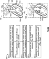
- FIG. 5A an alternate embodiment of a separating mechanism for use in the plug assembly 100 is illustrated, in accordance with an embodiment of the present disclosure.
- the outer case 60, the outer port 62, and the component 63 have been hidden from view in FIG. 5A to better illustrate the plug assembly 100.
- the plug assembly 100 of FIG. 5A uses a spring 160b as a separating mechanism (rather than the separator body 160 of FIG. 4 ) to push the first arm 150a and the second arm 150b apart.
- the spring 160b drives and/or maintains the first projection portion 154a through a first opening 147 in a passageway portion 146 of the sheath 140 and the second projection portion 154b through a second opening 149 in the passageway portion 146 of the sheath 140.
- the spring 160b may be placed between the first arm 150a and the second arm 150b during assembly.
- the spring 160b may be seated in a first indent 159a located in the first longitudinal portion 152a of the first arm 150a and a second indent 159b located in the second longitudinal portion 152b of the second arm 150b.
- FIG. 5B an alternate embodiment of a separating mechanism for use in the plug assembly 100 is illustrated, in accordance with an embodiment of the present disclosure.
- the outer case 60 and the outer port 62 have been hidden from view in FIG. 5B to better illustrate the plug assembly 100.
- the plug assembly 100 of FIG. 5B uses a connecting arm 157 as a separating mechanism (rather than the separator body 160 of FIG. 4 ) to push the first arm 150a and the second arm 150b apart.
- the connecting arm 157 connects the first arm 150a to the second arm 150b.
- first arm 150a to the second arm 150b are pinched together to fit into the sheath through-passage 141 and then the first arm 150a to the second arm 150b spring back into place to drive and/or maintain the first projection portion 154a through a first opening 147 in a passageway portion 146 of the sheath 140 and the second projection portion 154b through a second opening 149 in the passageway portion 146 of the sheath 140.
- the first arm 150a, the second 150b, and the connecting arm 157 have a predetermined rigidity to allow the first arm 150a and the second arm 150b to pinch together and then expand back out again.
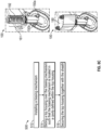
- FIGS. 6 and 7 an alternate embodiment of a separating mechanism for use in the plug assembly 100 is illustrated, in accordance with an embodiment of the present disclosure.
- the plug assembly 100 of FIGS. 6 and 7 uses a wedge shaped body 160c as a separating mechanism (rather than the separator body 160 of FIG. 4 ) to push the first arm 150a and the second arm 150b apart.
- the wedge shaped body 160c drives and/or maintains the first projection portion 154a through a first opening 147 in a passageway portion 146 of the sheath 140 and the second projection portion 154b through a second opening 149 in the passageway portion 146 of the sheath 140.
- the wedge shaped body 160c may be placed between the first arm 150a and the second arm 150b during assembly.
- a positioning bar 111 may be attached to the wedge shaped body 160c to insert the wedge shaped body 160c into place and/or maintain the wedge shaped body 160c in place.
- the positioning bar 111 may have threads that mate with the sheath 140 in order to screw the positioning bar 111 into the sheath 140 and push and/or maintain the wedge shaped body 160c in place.
- the positioning bar 111 may have no threads.
- the positioning bar 111 may be held in place by a locking pin.
- first longitudinal portion 152a and the second longitudinal portion 152b may also have a wedge shape, as illustrated in FIGS. 6 and 7 .
- FIGS. 8A , 8B , and 8C a flow chart of a method 500 of assembling the plug assembly 100 for plugging one or more ports 66, 62 of a gas turbine engine 20 is illustrated, in accordance with an embodiment of the present disclosure.
- the outer case 60 and the outer port 62 have been hidden from view in FIGS. 8A , 8B , and 8C to better illustrate the plug assembly 100.
- the method 500 is being illustrated and described largely with the embodiments of FIG. 4 , the method 500 is not limited to the embodiments illustrated in FIG. 4 and may also be applicable to the embodiments illustrated in FIGS. 5 and 6 .
- the inner end 142 of the sheath 140 is inserted into an inner port 66 of an inner casing 64 of the gas turbine engine 20.
- the plug assembly 100 may be configured to secure the outer casing 60 in place, a slider seal housing 110 in place, a slider seal 120 in place, a slider seal cover 130 in place, or any other component of the gas turbine engine 20 in place.
- the method 500 may further include that a slider seal housing 110 is secured onto a radially outward surface 65 of an inner casing 64 of the gas turbine 20.
- the method 500 may further include that a slider seal 120 is inserted into the slider seal housing 110.
- the slider seal housing 110 include a slider seal seat 112 configured to fit the slider seal 120 therein.
- the method 500 may further include that a slider seal cover 130 is secured to the slider seal housing 110.
- the slider seal cover 130 being configured to secure the slider seal 120 in the slider seal housing 110.
- the method 500 may further include that an inner end 142 of the sheath 140 is inserted through the cover through-passage 134, the seal through-passage 124, and the slider seal housing through-passage 114 and then the inner end 142 of the sheath 140 is inserted into an inner port 66 of an inner casing 64 of the gas turbine engine 20 (See FIG. 4 ).
- a first arm 150a is inserted into a sheath through-passage 141 of a sheath 140.
- the first arm 150a comprising a first longitudinal portion 152a and a first projection portion 154a.
- the first projection portion 154a may be oriented at about a right angle to the first longitudinal portion 152a.
- the first projection portion 154a of the first arm 150a is inserted through the first opening 147 prior to block 506.
- a second arm 150b is inserted into the sheath through-passage 141 of the sheath 140.
- the second arm 150b comprising a second longitudinal portion 152b and a second projection portion 154b.
- the second projection portion 154b may be oriented at about a right angle to the second longitudinal portion 152b.
- the second projection portion 154b of the second arm 150b is inserted through the second opening 149 prior to block 506.
- a c-seal 170 may be placed on the first arm 150a and the second arm 150b. Block 508 may be optional if a c-seal 170 is not required.
- a separating mechanism is inserted into the sheath through-passage 141 between the first arm 150a and the second arm 150b.
- the separating mechanism separates the first arm 150a from the second arm 150b. More specifically, the separating mechanism separates the first longitudinal portion 152a from the second longitudinal portion 152b.
- the separating mechanism may be a separator body 160.
- the separator body 160 may include a lower end 162, an upper end 164 located opposite the lower end 162, a separator body flange 166 dividing the separator body 160 into a lower portion 163 located at or proximate the lower end 162, and an upper portion 161 located at or proximate the upper end 164.
- the lower end 162 may be pointed or wedge shaped to help drive the first arm 150a and the second arm 150b apart in block 510.
- the separating mechanism is a wedge shaped body 160c and the first longitudinal portion 152a and the second longitudinal portion 152b have a wedge shape.
- a biasing mechanism 192 is installed.
- the biasing mechanism 192 may be a spring.
- the biasing mechanism 192 may be slid onto the upper portion 161 of the separator body 160.
- a top housing 180 is slid over the biasing mechanism 192 such that the biasing mechanism 192 is located in a cavity 186 defined within the top housing 180.
- the biasing mechanism 192 may be configured to apply a force to the first arm 150a and the second arm 150b when the biasing mechanism 192 is located in the cavity 186. The force being parallel to the first longitudinal portion 152a and the second longitudinal portion 152b.
- the top housing 180 is secured together with the sheath 140.
- the method 500 may further include that the plug assembly 100 is secured to the gas turbine engine 20. More specifically, the plug assembly 100 is secured to an outer casing 60 of the gas turbine engine 20.
- the plug assembly 100 may be secured to the gas turbine engine 20 by aligning a housing through-passage 189 within the top housing 180 and a flange through-passage 145 within a flange portion 148 of the sheath 140 with a threaded hole 61 in the outer casing 60 or in a component 63 attached to the outer casing 60, inserting a fastening mechanism 190 through the housing through-passage 189 and through the flange through-passage 145, and rotating the fastening mechanism 190 such that a threaded portion 194 of the fastening mechanism 190 interlocks with the threaded hole 61 to secure the plug assembly 100 to the gas turbine engine 20.
- radially outward is intended to be in the direction away from the engine central longitudinal axis A and radially inward is intended to be in the direction towards the engine central longitudinal axis A.
Landscapes
- Engineering & Computer Science (AREA)
- Mechanical Engineering (AREA)
- General Engineering & Computer Science (AREA)
- Turbine Rotor Nozzle Sealing (AREA)
Claims (15)
- Verfahren zum Zusammenbauen einer Steckerbaugruppe (100) zum Verschließen eines oder mehrerer Anschlüsse (66, 62) eines Gasturbinentriebwerks (20), wobei das Verfahren Folgendes umfasst:Einführen (504) eines ersten Arms (150a) in einen Ummantelungsdurchgang (141) einer Ummantelung (140), wobei der erste Arm (150a) einen ersten Längsabschnitt (152a) und einen ersten Vorsprungsabschnitt (154a) umfasst,Einführen (505) des ersten Vorsprungsabschnitts (154a) durch eine erste Öffnung (147) in einem Kanalabschnitt (146) der Ummantelung (140);Einführen (506) eines zweiten Arms (150b) in den Ummantelungsdurchgang (141), wobei der zweite Arm (150b) einen zweiten Längsabschnitt (152b) und einen zweiten Vorsprungsabschnitt (154b) umfasst;Einführen (507) des zweiten Vorsprungsabschnitts (154b) durch eine zweite Öffnung (149) in dem Kanalabschnitt (146);Einführen (510) eines Trennmechanismus (160; 160b; 157; 160c) in den Ummantelungsdurchgang (141) zwischen dem ersten Arm (150a) und dem zweiten Arm (150b);Installieren (512) eines Vorspannmechanismus (192);Schieben (514) eines oberen Gehäuses (180) über den Vorspannmechanismus (192), sodass sich der Vorspannmechanismus (192) in einem Hohlraum (186) befindet, der innerhalb des oberen Gehäuses (180) definiert ist, wobei der Vorspannmechanismus (192) dazu konfiguriert ist, eine Kraft auf den ersten Arm (150a) und den zweiten Arm (150b) aufzubringen, wenn sich der Vorspannmechanismus (192) in dem Hohlraum (186) befindet; undSichern (516) des oberen Gehäuses (180) zusammen mit der Ummantelung (140).
- Verfahren nach Anspruch 1, ferner umfassend:Sichern eines Schieberdichtungsgehäuses (110) auf eine radial nach außen gewandte Oberfläche (65) eines Innengehäuses (64) der Gasturbine (20);Einführen einer Schieberdichtung (120) in das Schieberdichtungsgehäuse (110), wobei das Schieberdichtungsgehäuse (110) einen Schieberdichtungssitz (112) beinhaltet, der so konfiguriert ist, dass die Schieberdichtung (120) darin hineinpasst; undSichern einer Schieberdichtungsabdeckung (130) an dem Schieberdichtungsgehäuse (110), wobei die Schieberdichtungsabdeckung (130) dazu konfiguriert ist, die Schieberdichtung (120) in dem Schieberdichtungsgehäuse (110) zu sichern.
- Verfahren nach Anspruch 2, wobei das Innengehäuse (64) ferner einen Innenanschluss (66) umfasst, das Schieberdichtungsgehäuse (110) ferner einen Schieberdichtungsgehäusedurchgang (114) umfasst, der mit dem Innenanschluss (66) ausgerichtet ist, die Schieberdichtung (120) ferner einen Dichtungsdurchgang (124) umfasst, der mit dem Innenanschluss (66) ausgerichtet ist, die Schieberdichtungsabdeckung (130) ferner einen Abdeckungsdurchgang (134) umfasst, der mit dem Innenanschluss (66) ausgerichtet ist, und das Verfahren ferner Folgendes umfasst:Einführen eines inneren Endes (142) der Ummantelung (140) durch den Abdeckungsdurchgang (134), den Dichtungsdurchgang (124) und den Schieberdichtungsgehäusedurchgang (114); undEinführen des inneren Endes (142) der Ummantelung (140) in den Innenanschluss (66) des Innengehäuses (64) des Gasturbinentriebwerks (20).
- Verfahren nach einem der Ansprüche 1 bis 3, ferner umfassend Einführen eines inneren Endes (142) der Ummantelung (140) in einen Innenanschluss (66) eines Innengehäuses (64) des Gasturbinentriebwerks (20).
- Verfahren nach einem der vorhergehenden Ansprüche, ferner umfassend Sichern der Steckerbaugruppe (100) an dem Gasturbinentriebwerk (20), wobei die Steckerbaugruppe (100) optional an einem Außengehäuse (60) des Gasturbinentriebwerks (20) gesichert ist.
- Verfahren nach Anspruch 5, wobei das Sichern der Steckerbaugruppe (100) an dem Gasturbinentriebwerk (20) ferner Folgendes umfasst:Ausrichten eines Gehäusedurchgangs (189) innerhalb des oberen Gehäuses (180) und eines Flanschdurchgangs (145) innerhalb eines Flanschabschnitts (148) der Ummantelung (140) mit einem Gewindeloch (61) in dem Außengehäuse (60) oder in einer Komponente (63), die an dem Außengehäuse (60) befestigt ist;Einführen eines Befestigungsmechanismus (190) durch den Gehäusedurchgang (189) und durch den Flanschdurchgang (145); undDrehen des Befestigungsmechanismus (190), sodass ein Gewindeabschnitt (194) des Befestigungsmechanismus (190) in das Gewindeloch (61) eingreift, um die Steckerbaugruppe (100) an dem Gasturbinentriebwerk (20) zu sichern.
- Verfahren nach einem der vorhergehenden Ansprüche, wobei der Vorspannmechanismus (192) eine Feder (160b) ist.
- Verfahren nach einem der vorhergehenden Ansprüche, wobei der Trennmechanismus ein Trennkörper (160) ist, wobei der Trennkörper (160) Folgendes umfasst:ein unteres Ende (162);ein oberes Ende (164), das sich gegenüber dem unteren Ende (162) befindet; undeinen Trennkörperflansch (166), der sich zwischen dem unteren Ende (162) und dem oberen Ende (164) befindet, wobei der Trennkörperflansch (166) den Trennkörper (160) unterteilt in:einen unteren Abschnitt (163), der sich an oder nahe dem unteren Ende (162) befindet; undeinen oberen Abschnitt (161), der sich an oder nahe dem oberen Ende (164) befindet, optional:
wobei das untere Ende (162) spitz oder keilförmig ist; und/oder ferner umfassend Platzieren (508) einer C-Dichtung (170) an dem ersten Arm (150a) und dem zweiten Arm (150b). - Verfahren nach Anspruch 8, wobei das Installieren des Vorspannmechanismus (192) ferner Schieben des Vorspannmechanismus (192) auf den oberen Abschnitt (161) des Trennkörpers (160) umfasst.
- Verfahren nach einem der Ansprüche 1 bis 7, wobei der Trennmechanismus ein keilförmiger Körper (160c) ist und wobei der erste Längsabschnitt (152a) und der zweite Längsabschnitt (152b) eine Keilform aufweisen.
- Verfahren nach einem der Ansprüche 1 bis 7, wobei der Trennmechanismus ein Verbindungsarm (157) ist, der den ersten Arm (150a) mit dem zweiten Arm (150b) verbindet.
- Steckerbaugruppe zum Verschließen eines oder mehrerer Anschlüsse (66, 62) eines Gasturbinentriebwerks, wobei die Steckerbaugruppe Folgendes umfasst:
eine Ummantelung (140), umfassend:ein inneres Ende (142);ein äußeres Ende (144), das sich gegenüber dem inneren Ende (142) befindet;einen Kanalabschnitt (146), der sich an oder nahe dem inneren Ende (142) befindet;einen Ummantelungsdurchgang (141), der sich von dem äußeren Ende (144) zu einer Ummantelungsdurchgangsbasis (143) nahe dem inneren Ende (142) erstreckt;eine erste Öffnung (147) in dem Durchgangsabschnitt (146); undeine zweite Öffnung (149) in dem Durchgangsabschnitt (146);einen ersten Arm (150a), umfassend:einen ersten Längsabschnitt (152a), der sich in dem Ummantelungsdurchgang (141) befindet; undeinen ersten Vorsprungsabschnitt (154a), der durch die erste Öffnung (147) vorsteht;einen zweiten Arm (150b), umfassend:einen zweiten Längsabschnitt (152b), der sich in dem Ummantelungsdurchgang (141) befindet; undeinen zweiten Vorsprungsabschnitt (154b), der durch die zweite Öffnung (149) vorsteht;einen Trennmechanismus (160; 160b; 157; 160c), der sich in dem Ummantelungsdurchgang (141) zwischen dem ersten Arm (150a) und dem zweiten Arm (150b) befindet, wobei der Trennmechanismus (160; 160b; 157; 160c) dazu konfiguriert ist, den ersten Arm (150a) von dem zweiten Arm (150b) zu trennen; undeinen Vorspannmechanismus (192), der dazu konfiguriert ist, eine Kraft auf den ersten Arm (150a) und den zweiten Arm (150b) aufzubringen, wobei die Kraft parallel zu dem ersten Längsabschnitt (152a) und dem zweiten Längsabschnitt (152b) verläuft; undein oberes Gehäuse (180), das an dem äußeren Ende (144) der Ummantelung (140) anliegt, wobei das obere Gehäuse (180) einen darin ausgebildeten Hohlraum (186) aufweist, wobei sich der Vorspannmechanismus (192) in dem Hohlraum (186) befindet. - Steckerbaugruppe (100) nach Anspruch 12, wobei der Trennmechanismus ein Trennkörper (160) ist, wobei der Trennkörper (160) Folgendes umfasst:ein unteres Ende (162);ein oberes Ende (164), das sich gegenüber dem unteren Ende (162) befindet; undeinen Trennkörperflansch (166), der sich zwischen dem unteren Ende (162) und dem oberen Ende (164) befindet, wobei der Trennkörperflansch (166) den Trennkörper (160) unterteilt in:einen unteren Abschnitt (163), der sich an oder nahe dem unteren Ende (162) befindet; undeinen oberen Abschnitt (161), der sich an oder nahe dem oberen Ende (164) befindet, wobei sich der Vorspannmechanismus (192) optional an dem oberen Abschnitt (161) des Trennkörpers (160) befindet.
- Steckerbaugruppe (100) nach Anspruch 13, wobei das untere Ende (162) spitz oder keilförmig ist, um das Auseinandertreiben des ersten Arms (150a) und des zweiten Arms (150b) zu erleichtern.
- Verfahren nach einem der Ansprüche 1 bis 7 oder Steckerbaugruppe (100) nach Anspruch 12, wobei der Trennmechanismus eine Feder (160b) ist.
Applications Claiming Priority (1)
| Application Number | Priority Date | Filing Date | Title |
|---|---|---|---|
| US17/557,844 US11624294B1 (en) | 2021-12-21 | 2021-12-21 | Restraining plug |
Publications (2)
| Publication Number | Publication Date |
|---|---|
| EP4202191A1 EP4202191A1 (de) | 2023-06-28 |
| EP4202191B1 true EP4202191B1 (de) | 2024-11-06 |
Family
ID=84547374
Family Applications (1)
| Application Number | Title | Priority Date | Filing Date |
|---|---|---|---|
| EP22215211.8A Active EP4202191B1 (de) | 2021-12-21 | 2022-12-20 | Rückhaltestecker |
Country Status (2)
| Country | Link |
|---|---|
| US (1) | US11624294B1 (de) |
| EP (1) | EP4202191B1 (de) |
Families Citing this family (1)
| Publication number | Priority date | Publication date | Assignee | Title |
|---|---|---|---|---|
| US12055058B2 (en) * | 2022-05-31 | 2024-08-06 | Pratt & Whitney Canada Corp. | Joint between gas turbine engine components with a spring element |
Family Cites Families (20)
| Publication number | Priority date | Publication date | Assignee | Title |
|---|---|---|---|---|
| US3157258A (en) * | 1961-06-16 | 1964-11-17 | Vincent G Dreesman | Torque limiting coupling and positive clutch mechanism |
| US3362160A (en) * | 1966-09-16 | 1968-01-09 | Gen Electric | Gas turbine engine inspection apparatus |
| US4591794A (en) * | 1982-12-28 | 1986-05-27 | United Technologies Corporation | Gas turbine access port plug electrostatic probe |
| US4815276A (en) | 1987-09-10 | 1989-03-28 | The United States Of America As Represented By The Secretary Of The Air Force | Borescope plug |
| US5115636A (en) * | 1990-09-12 | 1992-05-26 | General Electric Company | Borescope plug |
| FR2708071B1 (fr) * | 1993-07-21 | 1995-09-01 | Snecma | Bouchon amovible de deux trous. |
| US5867976A (en) | 1997-08-01 | 1999-02-09 | General Electric Company | Self-retained borescope plug |
| US6468033B1 (en) * | 2000-10-03 | 2002-10-22 | General Electric Company | Methods and apparatus for maintaining alignment of borescope plungers |
| US7231817B2 (en) * | 2005-01-18 | 2007-06-19 | Siemens Power Generation, Inc. | Inspection system for a turbine blade region of a turbine engine |
| FR2926329B1 (fr) * | 2008-01-15 | 2013-01-04 | Snecma | Agencement d'une bougie du type a semi-conducteur dans une chambre de combustion de moteur a turbine a gaz. |
| US8047769B2 (en) * | 2008-02-07 | 2011-11-01 | General Electric Company | Inspection port plug devices |
| US8197187B2 (en) * | 2008-12-29 | 2012-06-12 | Caterpillar Inc. | Inspection hole plug with a ball swivel |
| US9494052B2 (en) * | 2012-03-27 | 2016-11-15 | United Technologies Corporation | Dual-intent locator pin and removable plug for gas turbines |
| FR3006373B1 (fr) * | 2013-05-31 | 2015-05-22 | Snecma | Carter de turbomachine comportant un orifice d'endoscopie |
| US9880070B2 (en) * | 2013-06-21 | 2018-01-30 | United Technologies Corporation | Engine inspection apparatus and system |
| FR3015642B1 (fr) * | 2013-12-23 | 2018-03-02 | Safran Aircraft Engines | Bougie de turbomachine et son dispositif de fixation radiale |
| US9988929B2 (en) * | 2015-01-06 | 2018-06-05 | United Technologies Corporation | Borescope plug for gas turbine engine |
| US10041413B2 (en) * | 2015-06-05 | 2018-08-07 | General Electric Company | Igniter assembly for a gas turbine engine |
| US11434774B2 (en) * | 2016-08-08 | 2022-09-06 | Raytheon Technologies Corporation | Borescope plug |
| US11085322B2 (en) * | 2018-10-04 | 2021-08-10 | Raytheon Technologies Corporation | Borescope plug system |
-
2021
- 2021-12-21 US US17/557,844 patent/US11624294B1/en active Active
-
2022
- 2022-12-20 EP EP22215211.8A patent/EP4202191B1/de active Active
Also Published As
| Publication number | Publication date |
|---|---|
| US11624294B1 (en) | 2023-04-11 |
| EP4202191A1 (de) | 2023-06-28 |
Similar Documents
| Publication | Publication Date | Title |
|---|---|---|
| EP3543566B1 (de) | Rampenförmige abstandshalterringdichtung | |
| EP4219917A1 (de) | Verdrehsicherungsvorrichtung für befestigungselemente | |
| EP3584406B1 (de) | Klammer- und stiftausgleich für einen rotor | |
| US10704412B2 (en) | Bell crank and bar assembly | |
| EP4202191B1 (de) | Rückhaltestecker | |
| EP3533974B1 (de) | Variable schaufelarmhaltevorrichtung | |
| EP3418492B1 (de) | Zugankerrückhalteanordnung für turboluftstrahltriebwerk | |
| US11002147B2 (en) | Fixed vane pack retaining ring | |
| EP4202192B1 (de) | Rückhaltestecker | |
| EP3431716B1 (de) | Verstellbare schaufelanordnung und zugehöriges fertigungsverfahren | |
| US11286797B2 (en) | Gas turbine engine stator vane base shape | |
| US10883370B2 (en) | Dovetail weight system for rotor balance | |
| EP3760841B1 (de) | Mehrzweckdrehsicherungssperrbolzen | |
| EP3453837B1 (de) | Rückhaltesystem eines statoranordnung eines gebläseaustritts | |
| US12352180B2 (en) | Compressor rotor destacking apparatus and method | |
| EP4428342A1 (de) | Bolzenverbindung eines gasturbinenmotors | |
| US20220065116A1 (en) | Wound retaining wire |
Legal Events
| Date | Code | Title | Description |
|---|---|---|---|
| PUAI | Public reference made under article 153(3) epc to a published international application that has entered the european phase |
Free format text: ORIGINAL CODE: 0009012 |
|
| STAA | Information on the status of an ep patent application or granted ep patent |
Free format text: STATUS: THE APPLICATION HAS BEEN PUBLISHED |
|
| AK | Designated contracting states |
Kind code of ref document: A1 Designated state(s): AL AT BE BG CH CY CZ DE DK EE ES FI FR GB GR HR HU IE IS IT LI LT LU LV MC ME MK MT NL NO PL PT RO RS SE SI SK SM TR |
|
| RAP3 | Party data changed (applicant data changed or rights of an application transferred) |
Owner name: RTX CORPORATION |
|
| STAA | Information on the status of an ep patent application or granted ep patent |
Free format text: STATUS: REQUEST FOR EXAMINATION WAS MADE |
|
| 17P | Request for examination filed |
Effective date: 20231220 |
|
| RBV | Designated contracting states (corrected) |
Designated state(s): AL AT BE BG CH CY CZ DE DK EE ES FI FR GB GR HR HU IE IS IT LI LT LU LV MC ME MK MT NL NO PL PT RO RS SE SI SK SM TR |
|
| GRAP | Despatch of communication of intention to grant a patent |
Free format text: ORIGINAL CODE: EPIDOSNIGR1 |
|
| STAA | Information on the status of an ep patent application or granted ep patent |
Free format text: STATUS: GRANT OF PATENT IS INTENDED |
|
| INTG | Intention to grant announced |
Effective date: 20240528 |
|
| GRAS | Grant fee paid |
Free format text: ORIGINAL CODE: EPIDOSNIGR3 |
|
| GRAA | (expected) grant |
Free format text: ORIGINAL CODE: 0009210 |
|
| STAA | Information on the status of an ep patent application or granted ep patent |
Free format text: STATUS: THE PATENT HAS BEEN GRANTED |
|
| AK | Designated contracting states |
Kind code of ref document: B1 Designated state(s): AL AT BE BG CH CY CZ DE DK EE ES FI FR GB GR HR HU IE IS IT LI LT LU LV MC ME MK MT NL NO PL PT RO RS SE SI SK SM TR |
|
| REG | Reference to a national code |
Ref country code: GB Ref legal event code: FG4D |
|
| REG | Reference to a national code |
Ref country code: CH Ref legal event code: EP |
|
| REG | Reference to a national code |
Ref country code: DE Ref legal event code: R096 Ref document number: 602022007490 Country of ref document: DE |
|
| REG | Reference to a national code |
Ref country code: IE Ref legal event code: FG4D |
|
| REG | Reference to a national code |
Ref country code: LT Ref legal event code: MG9D |
|
| REG | Reference to a national code |
Ref country code: NL Ref legal event code: MP Effective date: 20241106 |
|
| PG25 | Lapsed in a contracting state [announced via postgrant information from national office to epo] |
Ref country code: IS Free format text: LAPSE BECAUSE OF FAILURE TO SUBMIT A TRANSLATION OF THE DESCRIPTION OR TO PAY THE FEE WITHIN THE PRESCRIBED TIME-LIMIT Effective date: 20250306 Ref country code: PT Free format text: LAPSE BECAUSE OF FAILURE TO SUBMIT A TRANSLATION OF THE DESCRIPTION OR TO PAY THE FEE WITHIN THE PRESCRIBED TIME-LIMIT Effective date: 20250306 Ref country code: HR Free format text: LAPSE BECAUSE OF FAILURE TO SUBMIT A TRANSLATION OF THE DESCRIPTION OR TO PAY THE FEE WITHIN THE PRESCRIBED TIME-LIMIT Effective date: 20241106 |
|
| PG25 | Lapsed in a contracting state [announced via postgrant information from national office to epo] |
Ref country code: FI Free format text: LAPSE BECAUSE OF FAILURE TO SUBMIT A TRANSLATION OF THE DESCRIPTION OR TO PAY THE FEE WITHIN THE PRESCRIBED TIME-LIMIT Effective date: 20241106 Ref country code: NL Free format text: LAPSE BECAUSE OF FAILURE TO SUBMIT A TRANSLATION OF THE DESCRIPTION OR TO PAY THE FEE WITHIN THE PRESCRIBED TIME-LIMIT Effective date: 20241106 |
|
| REG | Reference to a national code |
Ref country code: AT Ref legal event code: MK05 Ref document number: 1739558 Country of ref document: AT Kind code of ref document: T Effective date: 20241106 |
|
| PG25 | Lapsed in a contracting state [announced via postgrant information from national office to epo] |
Ref country code: BG Free format text: LAPSE BECAUSE OF FAILURE TO SUBMIT A TRANSLATION OF THE DESCRIPTION OR TO PAY THE FEE WITHIN THE PRESCRIBED TIME-LIMIT Effective date: 20241106 |
|
| PG25 | Lapsed in a contracting state [announced via postgrant information from national office to epo] |
Ref country code: ES Free format text: LAPSE BECAUSE OF FAILURE TO SUBMIT A TRANSLATION OF THE DESCRIPTION OR TO PAY THE FEE WITHIN THE PRESCRIBED TIME-LIMIT Effective date: 20241106 |
|
| PG25 | Lapsed in a contracting state [announced via postgrant information from national office to epo] |
Ref country code: NO Free format text: LAPSE BECAUSE OF FAILURE TO SUBMIT A TRANSLATION OF THE DESCRIPTION OR TO PAY THE FEE WITHIN THE PRESCRIBED TIME-LIMIT Effective date: 20250206 |
|
| PG25 | Lapsed in a contracting state [announced via postgrant information from national office to epo] |
Ref country code: GR Free format text: LAPSE BECAUSE OF FAILURE TO SUBMIT A TRANSLATION OF THE DESCRIPTION OR TO PAY THE FEE WITHIN THE PRESCRIBED TIME-LIMIT Effective date: 20250207 Ref country code: LV Free format text: LAPSE BECAUSE OF FAILURE TO SUBMIT A TRANSLATION OF THE DESCRIPTION OR TO PAY THE FEE WITHIN THE PRESCRIBED TIME-LIMIT Effective date: 20241106 Ref country code: AT Free format text: LAPSE BECAUSE OF FAILURE TO SUBMIT A TRANSLATION OF THE DESCRIPTION OR TO PAY THE FEE WITHIN THE PRESCRIBED TIME-LIMIT Effective date: 20241106 |
|
| PG25 | Lapsed in a contracting state [announced via postgrant information from national office to epo] |
Ref country code: PL Free format text: LAPSE BECAUSE OF FAILURE TO SUBMIT A TRANSLATION OF THE DESCRIPTION OR TO PAY THE FEE WITHIN THE PRESCRIBED TIME-LIMIT Effective date: 20241106 |
|
| PG25 | Lapsed in a contracting state [announced via postgrant information from national office to epo] |
Ref country code: RS Free format text: LAPSE BECAUSE OF FAILURE TO SUBMIT A TRANSLATION OF THE DESCRIPTION OR TO PAY THE FEE WITHIN THE PRESCRIBED TIME-LIMIT Effective date: 20250206 |
|
| PG25 | Lapsed in a contracting state [announced via postgrant information from national office to epo] |
Ref country code: SM Free format text: LAPSE BECAUSE OF FAILURE TO SUBMIT A TRANSLATION OF THE DESCRIPTION OR TO PAY THE FEE WITHIN THE PRESCRIBED TIME-LIMIT Effective date: 20241106 |
|
| PG25 | Lapsed in a contracting state [announced via postgrant information from national office to epo] |
Ref country code: DK Free format text: LAPSE BECAUSE OF FAILURE TO SUBMIT A TRANSLATION OF THE DESCRIPTION OR TO PAY THE FEE WITHIN THE PRESCRIBED TIME-LIMIT Effective date: 20241106 |
|
| PG25 | Lapsed in a contracting state [announced via postgrant information from national office to epo] |
Ref country code: EE Free format text: LAPSE BECAUSE OF FAILURE TO SUBMIT A TRANSLATION OF THE DESCRIPTION OR TO PAY THE FEE WITHIN THE PRESCRIBED TIME-LIMIT Effective date: 20241106 |
|
| PG25 | Lapsed in a contracting state [announced via postgrant information from national office to epo] |
Ref country code: RO Free format text: LAPSE BECAUSE OF FAILURE TO SUBMIT A TRANSLATION OF THE DESCRIPTION OR TO PAY THE FEE WITHIN THE PRESCRIBED TIME-LIMIT Effective date: 20241106 |
|
| PG25 | Lapsed in a contracting state [announced via postgrant information from national office to epo] |
Ref country code: SK Free format text: LAPSE BECAUSE OF FAILURE TO SUBMIT A TRANSLATION OF THE DESCRIPTION OR TO PAY THE FEE WITHIN THE PRESCRIBED TIME-LIMIT Effective date: 20241106 |
|
| PG25 | Lapsed in a contracting state [announced via postgrant information from national office to epo] |
Ref country code: CZ Free format text: LAPSE BECAUSE OF FAILURE TO SUBMIT A TRANSLATION OF THE DESCRIPTION OR TO PAY THE FEE WITHIN THE PRESCRIBED TIME-LIMIT Effective date: 20241106 |
|
| PG25 | Lapsed in a contracting state [announced via postgrant information from national office to epo] |
Ref country code: IT Free format text: LAPSE BECAUSE OF FAILURE TO SUBMIT A TRANSLATION OF THE DESCRIPTION OR TO PAY THE FEE WITHIN THE PRESCRIBED TIME-LIMIT Effective date: 20241106 |
|
| REG | Reference to a national code |
Ref country code: DE Ref legal event code: R097 Ref document number: 602022007490 Country of ref document: DE |
|
| PG25 | Lapsed in a contracting state [announced via postgrant information from national office to epo] |
Ref country code: LU Free format text: LAPSE BECAUSE OF NON-PAYMENT OF DUE FEES Effective date: 20241220 |
|
| PG25 | Lapsed in a contracting state [announced via postgrant information from national office to epo] |
Ref country code: SE Free format text: LAPSE BECAUSE OF FAILURE TO SUBMIT A TRANSLATION OF THE DESCRIPTION OR TO PAY THE FEE WITHIN THE PRESCRIBED TIME-LIMIT Effective date: 20241106 |
|
| PLBE | No opposition filed within time limit |
Free format text: ORIGINAL CODE: 0009261 |
|
| STAA | Information on the status of an ep patent application or granted ep patent |
Free format text: STATUS: NO OPPOSITION FILED WITHIN TIME LIMIT |
|
| PG25 | Lapsed in a contracting state [announced via postgrant information from national office to epo] |
Ref country code: MC Free format text: LAPSE BECAUSE OF FAILURE TO SUBMIT A TRANSLATION OF THE DESCRIPTION OR TO PAY THE FEE WITHIN THE PRESCRIBED TIME-LIMIT Effective date: 20241106 |
|
| REG | Reference to a national code |
Ref country code: BE Ref legal event code: MM Effective date: 20241231 |
|
| 26N | No opposition filed |
Effective date: 20250807 |
|
| PG25 | Lapsed in a contracting state [announced via postgrant information from national office to epo] |
Ref country code: BE Free format text: LAPSE BECAUSE OF NON-PAYMENT OF DUE FEES Effective date: 20241231 |
|
| PG25 | Lapsed in a contracting state [announced via postgrant information from national office to epo] |
Ref country code: IE Free format text: LAPSE BECAUSE OF NON-PAYMENT OF DUE FEES Effective date: 20241220 |
|
| PGFP | Annual fee paid to national office [announced via postgrant information from national office to epo] |
Ref country code: DE Payment date: 20251126 Year of fee payment: 4 |
|
| PGFP | Annual fee paid to national office [announced via postgrant information from national office to epo] |
Ref country code: FR Payment date: 20251120 Year of fee payment: 4 |