EP4202192A1 - Bouchon de retenue - Google Patents
Bouchon de retenue Download PDFInfo
- Publication number
- EP4202192A1 EP4202192A1 EP22215205.0A EP22215205A EP4202192A1 EP 4202192 A1 EP4202192 A1 EP 4202192A1 EP 22215205 A EP22215205 A EP 22215205A EP 4202192 A1 EP4202192 A1 EP 4202192A1
- Authority
- EP
- European Patent Office
- Prior art keywords
- cover
- connector body
- passage
- sheath
- slider seal
- Prior art date
- Legal status (The legal status is an assumption and is not a legal conclusion. Google has not performed a legal analysis and makes no representation as to the accuracy of the status listed.)
- Granted
Links
Images




Classifications
-
- F—MECHANICAL ENGINEERING; LIGHTING; HEATING; WEAPONS; BLASTING
- F01—MACHINES OR ENGINES IN GENERAL; ENGINE PLANTS IN GENERAL; STEAM ENGINES
- F01D—NON-POSITIVE DISPLACEMENT MACHINES OR ENGINES, e.g. STEAM TURBINES
- F01D21/00—Shutting-down of machines or engines, e.g. in emergency; Regulating, controlling, or safety means not otherwise provided for
- F01D21/003—Arrangements for testing or measuring
-
- F—MECHANICAL ENGINEERING; LIGHTING; HEATING; WEAPONS; BLASTING
- F01—MACHINES OR ENGINES IN GENERAL; ENGINE PLANTS IN GENERAL; STEAM ENGINES
- F01D—NON-POSITIVE DISPLACEMENT MACHINES OR ENGINES, e.g. STEAM TURBINES
- F01D25/00—Component parts, details, or accessories, not provided for in, or of interest apart from, other groups
- F01D25/24—Casings; Casing parts, e.g. diaphragms, casing fastenings
-
- B—PERFORMING OPERATIONS; TRANSPORTING
- B64—AIRCRAFT; AVIATION; COSMONAUTICS
- B64D—EQUIPMENT FOR FITTING IN OR TO AIRCRAFT; FLIGHT SUITS; PARACHUTES; ARRANGEMENT OR MOUNTING OF POWER PLANTS OR PROPULSION TRANSMISSIONS IN AIRCRAFT
- B64D29/00—Power-plant nacelles, fairings or cowlings
- B64D29/08—Inspection panels for power plants
-
- F—MECHANICAL ENGINEERING; LIGHTING; HEATING; WEAPONS; BLASTING
- F01—MACHINES OR ENGINES IN GENERAL; ENGINE PLANTS IN GENERAL; STEAM ENGINES
- F01D—NON-POSITIVE DISPLACEMENT MACHINES OR ENGINES, e.g. STEAM TURBINES
- F01D25/00—Component parts, details, or accessories, not provided for in, or of interest apart from, other groups
-
- F—MECHANICAL ENGINEERING; LIGHTING; HEATING; WEAPONS; BLASTING
- F01—MACHINES OR ENGINES IN GENERAL; ENGINE PLANTS IN GENERAL; STEAM ENGINES
- F01D—NON-POSITIVE DISPLACEMENT MACHINES OR ENGINES, e.g. STEAM TURBINES
- F01D25/00—Component parts, details, or accessories, not provided for in, or of interest apart from, other groups
- F01D25/24—Casings; Casing parts, e.g. diaphragms, casing fastenings
- F01D25/243—Flange connections; Bolting arrangements
-
- F—MECHANICAL ENGINEERING; LIGHTING; HEATING; WEAPONS; BLASTING
- F01—MACHINES OR ENGINES IN GENERAL; ENGINE PLANTS IN GENERAL; STEAM ENGINES
- F01D—NON-POSITIVE DISPLACEMENT MACHINES OR ENGINES, e.g. STEAM TURBINES
- F01D25/00—Component parts, details, or accessories, not provided for in, or of interest apart from, other groups
- F01D25/24—Casings; Casing parts, e.g. diaphragms, casing fastenings
- F01D25/26—Double casings; Measures against temperature strain in casings
- F01D25/265—Vertically split casings; Clamping arrangements therefor
-
- F—MECHANICAL ENGINEERING; LIGHTING; HEATING; WEAPONS; BLASTING
- F05—INDEXING SCHEMES RELATING TO ENGINES OR PUMPS IN VARIOUS SUBCLASSES OF CLASSES F01-F04
- F05D—INDEXING SCHEME FOR ASPECTS RELATING TO NON-POSITIVE-DISPLACEMENT MACHINES OR ENGINES, GAS-TURBINES OR JET-PROPULSION PLANTS
- F05D2220/00—Application
- F05D2220/30—Application in turbines
- F05D2220/32—Application in turbines in gas turbines
-
- F—MECHANICAL ENGINEERING; LIGHTING; HEATING; WEAPONS; BLASTING
- F05—INDEXING SCHEMES RELATING TO ENGINES OR PUMPS IN VARIOUS SUBCLASSES OF CLASSES F01-F04
- F05D—INDEXING SCHEME FOR ASPECTS RELATING TO NON-POSITIVE-DISPLACEMENT MACHINES OR ENGINES, GAS-TURBINES OR JET-PROPULSION PLANTS
- F05D2240/00—Components
- F05D2240/10—Stators
- F05D2240/14—Casings or housings protecting or supporting assemblies within
-
- F—MECHANICAL ENGINEERING; LIGHTING; HEATING; WEAPONS; BLASTING
- F05—INDEXING SCHEMES RELATING TO ENGINES OR PUMPS IN VARIOUS SUBCLASSES OF CLASSES F01-F04
- F05D—INDEXING SCHEME FOR ASPECTS RELATING TO NON-POSITIVE-DISPLACEMENT MACHINES OR ENGINES, GAS-TURBINES OR JET-PROPULSION PLANTS
- F05D2260/00—Function
- F05D2260/30—Retaining components in desired mutual position
- F05D2260/31—Retaining bolts or nuts
-
- F—MECHANICAL ENGINEERING; LIGHTING; HEATING; WEAPONS; BLASTING
- F05—INDEXING SCHEMES RELATING TO ENGINES OR PUMPS IN VARIOUS SUBCLASSES OF CLASSES F01-F04
- F05D—INDEXING SCHEME FOR ASPECTS RELATING TO NON-POSITIVE-DISPLACEMENT MACHINES OR ENGINES, GAS-TURBINES OR JET-PROPULSION PLANTS
- F05D2260/00—Function
- F05D2260/30—Retaining components in desired mutual position
- F05D2260/38—Retaining components in desired mutual position by a spring, i.e. spring loaded or biased towards a certain position
Definitions
- the subject matter disclosed herein relates generally to gas turbine engines and, more particularly, to a plug for plugging an inspection port in a gas turbine engine.
- Gas turbine engines typically operate at high rotational speeds and high temperatures for increased performance and efficiency.
- performance of an engine may be tied to proper operation and function of engine components.
- components may be damaged, fail or otherwise require maintenance.
- control of an engine may be based on the operation of components within an engine.
- Safety inspections and routine maintenance are often required to ensure safe operation and prevent engine failure.
- Many gas turbine engines include inspection ports to allow for inspection and/or maintenance of an engine. Conventional methods of sealing these ports can be expensive and in some cases, may lead to foreign object damage (FOD) due to improper installation during manufacture or maintenance.
- FOD foreign object damage
- some gas turbine engines may have dozens of ports.
- correct operation and installation of port components may be required for safe and efficient operation of an engine. There is a need in the art for port components for gas turbine engines.
- a method for assembling a plug assembly for plugging one or more ports of a gas turbine engine includes that a connector body and a cover operably connected to the connector body are inserted into a sheath through-passage of a sheath.
- the connector body including a rotatable joint operably connecting the cover to the connector body.
- the method also includes that a biasing mechanism configured to apply a force to the cover is installed, the cover is rotated relative to the connector body via the rotatable joint, a top housing is slid over the biasing mechanism such that the biasing mechanism abuts a bottom end of the top housing or is located in a cavity defined within the top housing, and the top housing is secured together with the sheath.
- further embodiments may include that a slider seal housing is secured onto a radially outward surface of an inner casing of the gas turbine engine and a slider seal is inserted into the slider seal housing, the slider seal housing including a slider seal seat configured to fit the slider seal therein.
- the method may further include that a slider seal cover is secured to the slider seal housing. The slider seal cover being configured to secure the slider seal in the slider seal housing.
- the inner casing further includes an inner port.
- the slider seal housing further includes a slider seal housing through-passage aligned with the inner port.
- the slider seal further includes a seal through-passage aligned with the inner port.
- further embodiments may include that the cover is rotated to be about parallel with a radially inward surface of the inner casing.
- cover further includes a first cover and a second cover.
- further embodiments may include that the second cover overlaps the first cover by a selected portion after the cover is rotated to be about parallel with a radially inward surface of the inner casing.
- further embodiments may include that the cover is rotated to be about parallel with the connector body prior to inserting the connector body and the cover operably connected to the connector body into the sheath through-passage of the sheath.
- further embodiments may include that the cover is rotated to be about parallel with the slider seal after inserting the connector body and the cover operably connected to the connector body into the sheath through-passage of the sheath.
- further embodiments may include that the cover is operably connected to the connector body.
- cover further includes a first cover and a second cover.
- the connector body further includes a first connector body and a second connector body.
- the rotatable joint further includes a first rotatable joint and a second rotatable joint.
- further embodiments may include that inserting the connector body and the cover operably connected to the connector body into the sheath through-passage of the sheath further includes that the first connector body and the first cover operably connected to the first connector body are inserted into the sheath through-passage of the sheath and the second connector body and the second cover operably connected to the second connector body are inserted into the sheath through-passage of the sheath.
- further embodiments may include that the plug assembly is secured to the gas turbine engine.
- further embodiments may include that the plug assembly is secured to an outer casing of the gas turbine engine.
- securing the plug assembly to the gas turbine engine further includes that a housing through-passage within the top housing is aligned with a threaded hole in the sheath, a fastening mechanism is inserted through the housing through-passage, and the fastening mechanism are rotated such that a threaded portion of the fastening mechanism interlocks with the threaded hole to secure the plug assembly to the gas turbine engine.
- connector body further includes a lower end, the rotatable joint being located at the lower end, an upper end located opposite the lower end, and a connector body flange located between the lower end and the upper end.
- the connector body flange dividing the connector body into a lower portion located at or proximate the lower end and an upper portion located at or proximate the upper end.
- further embodiments may include that installing the biasing mechanism further includes that the biasing mechanism is slide onto the upper portion of the connector body.
- further embodiments may include that the biasing mechanism is a spring.
- a plug assembly for plugging one or more ports of a gas turbine engine includes a sheath including an inner end, an outer end located opposite the inner end, and a sheath through-passage extending from the outer end to the inner end.
- the plug assembly includes a connector body passing through the sheath through-passage.
- the connector body including a rotatable joint.
- the plug assembly includes a cover operably connected to the connector body via the rotatable joint, a biasing mechanism configured to apply a force to the connector body, and a top housing including a bottom end and a connector passageway extending from the bottom end a top end of the top housing.
- the biasing mechanism abuts the bottom end or is located in the cavity at the bottom end.
- the connector body passes through the connector passageway.
- the connector body further includes a lower end.
- the rotatable joint being located at the lower end.
- the connector body further includes an upper end located opposite the lower end and a connector body flange located between the lower end and the upper end.
- the connector body flange dividing the connector body into a lower portion located at or proximate the lower end and an upper portion located at or proximate the upper end.
- further embodiments may include that the biasing mechanism is located on the upper portion of the connector body.
- FIG. 1 schematically illustrates a gas turbine engine 20.
- the gas turbine engine 20 is disclosed herein as a two-spool turbofan that generally incorporates a fan section 22, a compressor section 24, a combustor section 26, and a turbine section 28.
- the fan section 22 drives air along a bypass flow path B in a bypass duct, while the compressor section 24 drives air along a core flow path C for compression and communication into the combustor section 26 then expansion through the turbine section 28.
- FIG. 1 schematically illustrates a gas turbine engine 20.
- the gas turbine engine 20 is disclosed herein as a two-spool turbofan that generally incorporates a fan section 22, a compressor section 24, a combustor section 26, and a turbine section 28.
- the fan section 22 drives air along a bypass flow path B in a bypass duct
- the compressor section 24 drives air along a core flow path C for compression and communication into the combustor section 26 then expansion through the turbine section 28.
- the exemplary engine 20 generally includes a low speed spool 30 and a high speed spool 32 mounted for rotation about an engine central longitudinal axis A relative to an engine static structure 36 via several bearing systems 38. It should be understood that various bearing systems 38 at various locations may alternatively or additionally be provided, and the location of bearing systems 38 may be varied as appropriate to the application.
- the low speed spool 30 generally includes an inner shaft 40 that interconnects a fan 42, a low pressure compressor 44 and a low pressure turbine 46.
- the inner shaft 40 is connected to the fan 42 through a speed change mechanism, which in exemplary gas turbine engine 20 is illustrated as a geared architecture 48 to drive the fan 42 at a lower speed than the low speed spool 30.
- the high speed spool 32 includes an outer shaft 50 that interconnects a high pressure compressor 52 and high pressure turbine 54.
- a combustor 56 is arranged in exemplary gas turbine 20 between the high pressure compressor 52 and the high pressure turbine 54.
- An engine static structure 36 is arranged generally between the high pressure turbine 54 and the low pressure turbine 46.
- the engine static structure 36 further supports bearing systems 38 in the turbine section 28.
- the inner shaft 40 and the outer shaft 50 are concentric and rotate via bearing systems 38 about the engine central longitudinal axis A which is collinear with their longitudinal axes.
- stator vanes 45 in the low pressure compressor 44 and stator vanes 55 in the high pressure compressor 52 may be adjustable during operation of the gas turbine engine 20 to support various operating conditions. In other embodiments, the stator vanes 45, 55 may be held in a fixed position.
- the turbines 46, 54 rotationally drive the respective low speed spool 30 and high speed spool 32 in response to the expansion. It will be appreciated that each of the positions of the fan section 22, compressor section 24, combustor section 26, turbine section 28, and fan drive gear system 48 may be varied. For example, gear system 48 may be located aft of combustor section 26 or even aft of turbine section 28, and fan section 22 may be positioned forward or aft of the location of gear system 48.
- the engine 20 in one example is a high-bypass geared aircraft engine.
- the engine 20 bypass ratio is greater than about six (6), with an example embodiment being greater than about ten (10)
- the geared architecture 48 is an epicyclic gear train, such as a planetary gear system or other gear system, with a gear reduction ratio of greater than about 2.3
- the low pressure turbine 46 has a pressure ratio that is greater than about five.
- the engine 20 bypass ratio is greater than about ten (10:1)
- the fan diameter is significantly larger than that of the low pressure compressor 44
- the low pressure turbine 46 has a pressure ratio that is greater than about five 5:1.
- Low pressure turbine 46 pressure ratio is pressure measured prior to inlet of low pressure turbine 46 as related to the pressure at the outlet of the low pressure turbine 46 prior to an exhaust nozzle.
- the geared architecture 48 may be an epicycle gear train, such as a planetary gear system or other gear system, with a gear reduction ratio of greater than about 2.3:1. It should be understood, however, that the above parameters are only exemplary of one embodiment of a geared architecture engine and that the present disclosure is applicable to other gas turbine engines including direct drive turbofans.
- the fan section 22 of the engine 20 is designed for a particular flight condition--typically cruise at about 0.8Mach and about 35,000 feet (10,688 meters).
- 'TSFC' Thrust Specific Fuel Consumption
- Low fan pressure ratio is the pressure ratio across the fan blade alone, without a Fan Exit Guide Vane (“FEGV”) system.
- the low fan pressure ratio as disclosed herein according to one non-limiting embodiment is less than about 1.45.
- Low corrected fan tip speed is the actual fan tip speed in ft/sec divided by an industry standard temperature correction of [(Tram °R)/(518.7 °R)] 0.5 .
- the "Low corrected fan tip speed” as disclosed herein according to one non-limiting embodiment is less than about 1150 ft/second (350.5 m/sec).
- FIGS. 2 and 3 a graphical representation of a plug assembly 100 (see also FIGS. 3-10 ) located within a gas turbine engine 20 is illustrated, in accordance with an embodiment of the present disclosure.
- the plug assembly 100 may be a borescope plug assembly and inspection port assembly.
- the plug assembly 100 are shown within an outer port 62 located within an outer casing 60 of the gas turbine engine 20 and an inner port 66 located in an inner casing 64 of the gas turbine engine 20.
- the port 62 may be a borescope port or an inspection port.
- the outer casing 60 may be a high pressure turbine case.
- the outer casing 60 may also be a lower pressure turbine case, a diffuser case, a high pressure compressor case, or any other case that requires an in section port in the gas turbine engine 20.
- the plug assembly 100 extend radially inward toward the engine central longitudinal axis A of the gas turbine engine 20. As illustrated in FIG. 2 , the plug assembly 100 may extend from the inner port 66 to the outer port 62.
- the inner casing 64 is located radially inward from the outer casing 60.
- the inner casing 64 may be a mid-turbine frame (MTF) vane casing. It is understood that the inner casing 64 is not limited to the MTF vane casing and the embodiment described herein are applicable to the inner casing 64 being any other casing or component located within the gas turbine engine 20 that is radially inward from the outer casing 60.
- MTF mid-turbine frame
- the inner casing 64 includes a radially inward surface 67 and a radially outward surface 65 located opposite the radially inward surface 67.
- the radially outward surface 65 is located radially outward of the radially inward surface 67.
- the inner port 66 extends from the radially inward surface 67 to the radially outward surface 65.
- the inner port 66 and the outer port 62 may be located in the turbine section 28 of the gas turbine engine 20. It is understood that the embodiments disclosed herein are not limited to the inner port 66 and the outer port 62 being located in the turbine section 28 of the gas turbine engine 20, and therefore the inner port 66 and the outer port 62 may be located in other sections of the gas turbine engine.
- the turbine section 28 is located aft of the combustor section 26.
- the turbine section 28 includes a plurality of vanes 68 extending circumferentially around the engine central longitudinal axis A.
- the inner port 66 and the outer port 62 may be located interposed circumferentially between two adjacent vanes 68, as illustrated in FIG. 3 .
- the plug assembly 100 may allow inspection into the outer port 62 and inner port 66.
- the plug assembly 100 provides access to the gas turbine engine 20 radially inward of the outer port 62 and/or the inner port 66 for mechanical diagnostics or other diagnostic reasons.
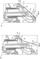
- FIGS. 4 and 5 a cross-sectional view of a plug assembly 100 is illustrated, in accordance with an embodiment of the present disclosure.
- the plug assembly 100 may be configured to secure an outer casing 60 in place, a slider seal housing 110 in place, a slider seal 120 in place, a slider seal cover 130 in place, or any other component of the gas turbine engine 20 in place. Further it is understood that while the plug assembly 100 has been described herein as securing the slider seal cover 130 in place, the plug assembly 100 may secure any component of the gas turbine engine 20 in place.
- the plug assembly 100 of FIGS. 4 and 5 may include the slider seal housing 110, the slider seal 120, the slider seal cover 130, a sheath 140, a cover 150, a connector body 160, a top housing 180, one or more fastening mechanism 190, and a biasing mechanism 192.
- the slider seal housing 110 abuts the radially outward surface 65 of the inner casing 64.
- the slider seal housing 110 may be secured to the radially outward surface 65 of the inner casing 64.
- the slider seal housing 110 may be secured to the radially outward surface 65 of the inner casing 64 via a weld or any other attachment method know to one of skill in the art.
- the slider seal housing 110 includes a slider seal seat 112 configured to fit the slider seal 120 therein.
- the slider seal 120 is configured to fit within the slider seal seat 112.
- the slider seal 120 is secured within the slider seal seat 112 by a slider seal cover 130.
- the slider seal cover 130 is secured to the slider seal housing 110.
- the slider seal cover 130 may be secured to the slider seal housing 110 via a weld or any other attachment method know to one of skill in the art.
- the slider seal cover 130 is configured to maintain or entrap the slider seal 120 within the slider seal housing 110 such that the slider seal 120 is free to slide between the slider seal cover 130 and slider seal housing 110 and is not fixed in place.
- the slider seal cover 130 may be configured to allow the slider seal 120 to move freely relative to the slider seal cover 130 and the slider seal housing 110.
- the slider seal housing 110 may be circular in shape with a slider seal housing through-passage 114.
- the slider seal 120 may be circular in shape with a seal through-passage 124.
- the slider seal cover 130 may be circular in shape with a cover through-passage 134.
- the connector body 160 is configured to pass through the sheath 140 with the cover 150 and the cover 150 is configured to cover the inner port 66.
- the cover 150 may be configured too completely cover the inner port 66 or partially cover the inner port 66.
- the cover 150 may compress against the slider seal 120.
- the cover 150 may be configured too partially cover the seal through-passage 124 to plug the inner port 66.
- the sheath 140 includes an inner end 142 and outer end 144 located radially outward from the inner end 142 when the plug assembly 100 is installed in the gas turbine engine 20.
- a sheath through-passage 141 extends through the sheath 140 from the inner end 142 to the outer end 144.
- the top housing 180 includes a top end 184 and a bottom end 182 located opposite the top end 184.
- the bottom end 182 of the top housing 180 abuts the outer end 144 of the sheath 140.
- the top housing 180 may include a cavity 186 extending from the bottom end 182 of the top housing 180 into the top housing 180 to a base 188.
- the cavity 186 is a blind hole as it does not pass completely through the top housing 180.
- no cavity 186 may be present in the top housing 180 the biasing mechanism 192 illustrated may abut the bottom end 182 of the top housing 180.
- the top housing 180 includes a connector passageway 181 that extends from the top end 184 to bottom end 182 or the base 188 if the cavity 186 is present.
- the top housing 180 is slid over the upper end 164 of the connector body 160 by sliding the upper end 164 of the connector body 160 through the connector passageway 181.
- the upper end 164 of the connector body 160 is slid through the connector passageway 181 and the upper end 164 projects out of the connector passageway 181 past the top end 184 of the top housing 180, such that a locking pin through-passage 168 is fully accessible by a locking pin 196.
- the cavity 186 may be configured to align with the sheath through-passage 141.
- a portion of the connector body 160 is located within the combined cavity defined by the cavity 186 and the sheath through-passage 141.
- the connector body 160 extends across the cavity 186 and the sheath through-passage 141.
- the connector body 160 includes a lower end 162 and an upper end 164 located opposite the lower end 162.
- the connector body 160 includes a rotatable joint 169 at the lower end 162.
- the cover 150 is operably connected to the connector body 160 at the rotatable joint 169.
- the cover 150 is configured to rotate relative to the connector body 160 at the rotatable joint 169.
- the cover 150 may be rotated to be substantially parallel or roughly parallel (i.e., about parallel) with the connector body 160 in order to fit through the sheath through-passage 141 during installation and then the cover 150 may be rotated to be substantially parallel or roughly parallel with the slider seal 120.
- the plug assembly 100 is configured to press the cover 150 into the slider seal 120 using a biasing mechanism 192 in order to seal the inner port 66.
- the length of the cover 150 is larger than the diameter of the sheath through-passage 141.
- the connector body 160 includes a connector body flange 166 located between the upper end 164 and the lower end 162.
- the connector body flange 166 includes an upper surface 165 and a lower surface 167 located opposite the upper surface 165.
- the connector body flange 166 divides or separates the connector body flange 166 into an upper portion 161 and a lower portion 163.
- the upper portion 161 is located at or proximate the upper end 164 and the lower portion 163 is located at or proximate the lower end 162.
- the biasing mechanism 192 may be interposed between the base 188 of the cavity 186 and the upper surface 165 of the connector body flange 166. If the cavity 186 is not present, the biasing mechanism 192 may be interposed between the bottom end 182 of the top housing 180 and the upper surface 165 of the connector body flange 166. In an embodiment, the biasing mechanism 192 may be a spring. The biasing mechanism 192 applies a force against the base 188 or the bottom end 182 and the upper surface 165 and pushes the upper surface 165 and the connector body 160 radially inward towards the inner port 66, which applies a radially inward force to the cover 150 and the cover 150 then applies a force to the slider seal 120.
- the connector body 160 includes a locking pin through-passage 168 located proximate the upper end 164.
- the locking pin through-passage 168 is configured to fit a locking pin 196 therein.
- the locking pin 196 may be configured to lock the connector body 160 in place relative to the top housing 180.
- the plug assembly 100 further includes one or more fastening mechanisms 190 configured to secure the plug assembly 100 to the outer casing 60.
- the one or more fastening mechanisms 190 passes through the top housing 180 to secure the plug assembly 100 to the outer casing 60.
- the fastening mechanism 190 may be a bolt.
- the fastening mechanism 190 may have a threaded portion 194.
- the fastening mechanism 190 passes through a housing through-passage 189 in the top housing 180 to secure within a threaded hole (not shown) located in the sheath 140.
- the threaded portion 194 is configured to interlock with the threaded hole (not shown) when the fastening mechanism 190 is rotated.
- FIGS. 6 and 7 an alternate embodiment of a separating mechanism for use in the plug assembly 100 is illustrated, in accordance with an embodiment of the present disclosure.
- the plug assembly 100 of FIG. 6 uses a connector body 160 that is composed of a first connector body 160a and a second connector body 160b.
- the connector body 160 is divided into the first connector body 160a and a second connector body 160b along a seam 199 that stretches from the lower end 162 to the upper end 164.
- the first connector body 160a extends from the upper end 164 to the lower end 162 and the second connector body 160b extends from the upper end 164 to the lower end 162.
- the plug assembly 100 of FIG. 6 uses a cover 150 that is composed of a first cover 150a and a second cover 150b.
- the plug assembly 100 of FIG. 6 uses a rotatable joint 169 that is composed of a first rotatable joint 169a and a second rotatable joint 169b.
- the first connector body 160a includes the first rotatable joint 169a located at the lower end 162 and the second connector body 160b the second rotatable joint 169b located at the lower end 162.
- the first cover 150a may be operably or rotatably connected to first connector body 160a at the first rotatable joint 169a.
- the second cover 150b may be operably or rotatably connected to the second connector body 160b at the second rotatable joint 169b.
- the first cover 150a may be rotated to be substantially parallel or roughly parallel with the first connector body 160a in order to fit through the sheath through-passage 141 during installation and then the first cover 150a may be rotated to be substantially parallel or roughly parallel with the slider seal 120.
- the plug assembly 100 is configured to press the first cover 150a into the slider seal 120 using a biasing mechanism 192 in order to seal the inner port 66.
- the second cover 150b may be rotated to be substantially parallel or roughly parallel with the second connector body 160b in order to fit through the sheath through-passage 141 during installation and then the second cover 150b may be rotated to be substantially parallel or roughly parallel with the slider seal 120.
- the plug assembly 100 is configured to press the second cover 150b into the slider seal 120 using a biasing mechanism 192 in order to seal the inner port 66.
- the second cover 150b may overlap the first cover 150a by a selected portion 151 in order to achieve a better seal between the first cover 150a and the second cover 150b, such that air leakage between the first cover 150a and the second cover 150b is reduced or eliminated.
- the first cover 150a may overlap the second cover 150b by a selected portion 151 in order to achieve a better seal between the first cover 150a and the second cover 150b, such that air leakage between the first cover 150a and the second cover 150b is reduced or eliminated.
- the first cover 150a may abut the second cover 150b.
- FIGS. 8 and 9 an alternate embodiment of a cover 150 for use in the plug assembly 100 is illustrated, in accordance with an embodiment of the present disclosure.
- the plug assembly 100 of FIGS. 7 and 8 seals the inner port 66 by compressing the cover 150 into the radially inward surface 67 of the inner casing 64.
- the cover 150 may be rotated to be substantially parallel or roughly parallel with the connector body 160 in order to fit through the sheath through-passage 141, the cover through-passage 134 of the slider seal cover 130, the seal through-passage 124 of the slider seal 120, the slider seal housing through-passage 114 of the slider seal housing 110, and the inner port 66 during installation, then the cover 150 may be rotated to be substantially parallel or roughly parallel with the radially inward surface 67 of the inner casing 64.
- the plug assembly 100 is configured to pull the cover 150 radially outward into the radially inward surface 67 using a tension mechanism (not shown) or a pressure differential between the gas turbine engine 20 radially inward of the inner casing 64 and the gas turbine engine 20 radially outward of the inner casing 64.
- the locking pin 196 of a mechanism similar to the locking pin 196 may be used to prevent the cover 150 and the connector body 160 from falling radially inward into the gas turbine engine 20.
- the cover 150 of FIGS. 8 and FIG. 9 may be composed of a first cover 150a and a second cover 150b as described previously in relations to FIG.6 .
- the connector body 160 of FIGS. 8 and FIG. 9 may be composed of a first connector body 160a and a second connector body 160b as described previously in relations to FIG.6 .
- the rotatable joint 169 of FIGS. 8 and FIG. 9 may be composed of a first rotatable joint 169a and a second rotatable joint 169b as described previously in relations to FIG.6 .
- FIGS. 10A , 10B , and 10C a flow chart of a method 500 of assembling the plug assembly 100 for plugging one or more ports 66, 62 of a gas turbine engine 20 is illustrated, in accordance with an embodiment of the present disclosure.
- the method 500 is being illustrated and described largely with the embodiments of FIGS. 4 and 5 , the method 500 is not limited to the embodiments illustrated in FIGS. 4-5 and may also be applicable to the embodiments illustrated in FIGS. 6-9 .
- a connector body 160 and a cover 150 operably connected to the connector body 160 are inserted into a sheath through-passage 141 of a sheath 140.
- the connector body 160 including a rotatable joint 169 located operably connecting the cover 150 to the connector body 160.
- the method 500 may also include operably connecting the cover 150 to the connector body 160.
- the method 500 may additionally include that the cover 150 is rotated to be about parallel with the connector body 160 prior to inserting the connector body 160 and the cover 150 into the sheath through-passage 141 of the sheath 140. This may be necessary to fit the cover 150 and the connector body 160 through the sheath through-passage 141 of a sheath 140.
- the cover 150 may further include a first cover 150a and a second cover 150b.
- the connector body 160 may further include a first connector body 160a and a second connector body 160b, and the rotatable j oint 169 may further include a first rotatable joint 169a and a second rotatable joint 169b.
- the method 500 may include that a first connector body 160a and the first cover 150a operably connected to the first connector body 160a is inserted into the sheath through-passage 141 of the sheath 140 and a second connector body 160b and the second cover 150b operably connected to the second connector body 160b is inserted into the sheath through-passage 141 of the sheath 140.
- the first cover 150a and a second cover 150b may be fit together at a seam 99 to create a single cover 150.
- the second cover 150b may overlap the first cover 150a by a selected portion 151 when fit together.
- a biasing mechanism 192 configured to apply a force to the cover 150 is installed.
- the biasing mechanism 192 may apply the force to the cover 150 through the connector body 160.
- Block 506 may further include that the biasing mechanism 192 is slid onto the upper portion 161 of the connector body 160.
- the biasing mechanism 192 may be a spring.
- the cover 150 is rotated relative to the connector body 160 via the rotatable joint 169.
- the cover 150 may be rotated to be about parallel with the slider seal 120.
- Block 508 may occur before or after block 510 and/or block 512.
- a top housing 180 is slid over the biasing mechanism 192 such that the biasing mechanism 192 abuts a bottom end 182 of the top housing 180 or is located in a cavity 186 defined within the top housing 180.
- the top housing 180 is secured together with the sheath 140.
- the top housing 180 may be secured together with the sheath 140 using one or more fastening mechanism 190.
- the method 500 may also include that a slider seal housing 110 is secured onto a radially outward surface 65 of an inner casing 64 of the gas turbine engine 20 and a slider seal 120 is inserted into the slider seal housing 110.
- the slider seal housing 110 including a slider seal seat 112 configured to fit the slider seal 120 therein.
- the method 500 may also include that a slider seal cover 130 is secured to the slider seal housing 110.
- the slider seal cover 130 being configured to secure the slider seal 120 in the slider seal housing 110 such that the slider seal 120 may be free to move.
- the method 500 may further include that the cover 150 is inserted through the cover through-passage 134, the seal through-passage 124, the slider seal housing through-passage 114, and the inner port 66 of the inner casing 64.
- the method 500 may also include the cover 150 is rotated to be about parallel with a radially inward surface 67 of the inner casing 64 after the cover 150 passes through the cover through-passage 134, the seal through-passage 124, the slider seal housing through-passage 114, and the inner port 66 of the inner casing 64.
- the cover 150 may further comprises a first cover 150a and a second cover 150b.
- the second cover 150b may overlap the first cover 150a by a selected portion 151 after the cover 150 is rotated to be about parallel with a radially inward surface 67 of the inner casing 64.
- the method 500 may include securing the plug assembly 100 to the gas turbine engine 20.
- the plug assembly 100 may be secured to an outer casing 60 of the gas turbine engine 20.
- the plug assembly 100 may be secured to an outer casing 60 of the gas turbine engine 20 by securing the sheath 140 to the outer casing 60.
- the plug assembly 100 may be secured to the gas turbine engine 20 by aligning a housing through-passage 189 within the top housing 180 with a threaded hole in the sheath 140, inserting a fastening mechanism 190 through the housing through-passage 189, and rotating the fastening mechanism 190 such that a threaded portion 194 of the fastening mechanism 190 interlocks with the threaded hole to secure the plug assembly 100 to the gas turbine engine 20.
- radially outward is intended to be in the direction away from the engine central longitudinal axis A and radially outward is intended to be in the direction towards the engine central longitudinal axis A.
Landscapes
- Engineering & Computer Science (AREA)
- Mechanical Engineering (AREA)
- General Engineering & Computer Science (AREA)
- Aviation & Aerospace Engineering (AREA)
- Turbine Rotor Nozzle Sealing (AREA)
Priority Applications (1)
| Application Number | Priority Date | Filing Date | Title |
|---|---|---|---|
| EP26154382.1A EP4711589A2 (fr) | 2021-12-21 | 2022-12-20 | Bouchon de retenue |
Applications Claiming Priority (1)
| Application Number | Priority Date | Filing Date | Title |
|---|---|---|---|
| US17/558,019 US12385411B2 (en) | 2021-12-21 | 2021-12-21 | Restraining plug |
Related Child Applications (1)
| Application Number | Title | Priority Date | Filing Date |
|---|---|---|---|
| EP26154382.1A Division EP4711589A2 (fr) | 2021-12-21 | 2022-12-20 | Bouchon de retenue |
Publications (2)
| Publication Number | Publication Date |
|---|---|
| EP4202192A1 true EP4202192A1 (fr) | 2023-06-28 |
| EP4202192B1 EP4202192B1 (fr) | 2026-01-28 |
Family
ID=84547174
Family Applications (2)
| Application Number | Title | Priority Date | Filing Date |
|---|---|---|---|
| EP22215205.0A Active EP4202192B1 (fr) | 2021-12-21 | 2022-12-20 | Bouchon de retenue |
| EP26154382.1A Pending EP4711589A2 (fr) | 2021-12-21 | 2022-12-20 | Bouchon de retenue |
Family Applications After (1)
| Application Number | Title | Priority Date | Filing Date |
|---|---|---|---|
| EP26154382.1A Pending EP4711589A2 (fr) | 2021-12-21 | 2022-12-20 | Bouchon de retenue |
Country Status (2)
| Country | Link |
|---|---|
| US (2) | US12385411B2 (fr) |
| EP (2) | EP4202192B1 (fr) |
Citations (3)
| Publication number | Priority date | Publication date | Assignee | Title |
|---|---|---|---|---|
| US5115636A (en) * | 1990-09-12 | 1992-05-26 | General Electric Company | Borescope plug |
| US5431534A (en) * | 1993-07-21 | 1995-07-11 | (S.N.E.C.M.A.) Societe National D'etude Et De Construction De Moteurs D'aviation | Removable inspection hole plug |
| US20150125267A1 (en) * | 2013-11-04 | 2015-05-07 | Clifford Hatcher, JR. | Standardized gas turbine inspection port system |
Family Cites Families (6)
| Publication number | Priority date | Publication date | Assignee | Title |
|---|---|---|---|---|
| US4815276A (en) | 1987-09-10 | 1989-03-28 | The United States Of America As Represented By The Secretary Of The Air Force | Borescope plug |
| US5867976A (en) | 1997-08-01 | 1999-02-09 | General Electric Company | Self-retained borescope plug |
| US8047769B2 (en) * | 2008-02-07 | 2011-11-01 | General Electric Company | Inspection port plug devices |
| GB2504612B (en) * | 2011-05-09 | 2014-09-24 | Rolls Royce Plc | An apparatus for supporting a tool in an assembled apparatus |
| US9157638B2 (en) * | 2012-01-31 | 2015-10-13 | General Electric Company | Adaptor assembly for removable components |
| US11242804B2 (en) * | 2017-06-14 | 2022-02-08 | General Electric Company | Inleakage management apparatus |
-
2021
- 2021-12-21 US US17/558,019 patent/US12385411B2/en active Active
-
2022
- 2022-12-20 EP EP22215205.0A patent/EP4202192B1/fr active Active
- 2022-12-20 EP EP26154382.1A patent/EP4711589A2/fr active Pending
-
2025
- 2025-08-11 US US19/296,326 patent/US20250369369A1/en active Pending
Patent Citations (3)
| Publication number | Priority date | Publication date | Assignee | Title |
|---|---|---|---|---|
| US5115636A (en) * | 1990-09-12 | 1992-05-26 | General Electric Company | Borescope plug |
| US5431534A (en) * | 1993-07-21 | 1995-07-11 | (S.N.E.C.M.A.) Societe National D'etude Et De Construction De Moteurs D'aviation | Removable inspection hole plug |
| US20150125267A1 (en) * | 2013-11-04 | 2015-05-07 | Clifford Hatcher, JR. | Standardized gas turbine inspection port system |
Also Published As
| Publication number | Publication date |
|---|---|
| US12385411B2 (en) | 2025-08-12 |
| US20230193780A1 (en) | 2023-06-22 |
| EP4711589A2 (fr) | 2026-03-18 |
| US20250369369A1 (en) | 2025-12-04 |
| EP4202192B1 (fr) | 2026-01-28 |
Similar Documents
| Publication | Publication Date | Title |
|---|---|---|
| US11840930B2 (en) | Component with feather seal slots for a gas turbine engine | |
| US11506071B2 (en) | Piston ring shuttle carrier | |
| US10704412B2 (en) | Bell crank and bar assembly | |
| US10907477B2 (en) | Clip and pin balance for rotor | |
| EP4202191B1 (fr) | Bouchon de retenue | |
| EP4202192B1 (fr) | Bouchon de retenue | |
| EP3517738A1 (fr) | Joint d'air externe d'une aube pour un moteur de turbine à gaz | |
| EP3712586B1 (fr) | Bouchon pour test de pression et procede de test de pression | |
| US11002147B2 (en) | Fixed vane pack retaining ring | |
| US11286797B2 (en) | Gas turbine engine stator vane base shape | |
| EP3760841B1 (fr) | Goupille de verrouillage anti-rotation à usages multiples | |
| EP3431716A1 (fr) | Ensemble d'aubes à calage variable et méthode d'assamblage associée | |
| US11268442B2 (en) | Mid mount sleeve arrangement | |
| US11181004B2 (en) | Confinement of a rope seal about a passage using a backing plate | |
| EP3971389A1 (fr) | Anneau de retenue de tube anti-vortex et panier d'alésage | |
| EP3453837B1 (fr) | Système de rétention d'ensemble de stator de sortie de ventilateur | |
| US12228043B1 (en) | Carbon seal covers | |
| US12352180B2 (en) | Compressor rotor destacking apparatus and method | |
| EP4372208A1 (fr) | Joint d'étanchéité pour moteur à turbine à gaz | |
| EP4560114A1 (fr) | Joint d'étanchéité pour segment de piston | |
| US9835091B2 (en) | Multiple piece shroud feedthru enclosure | |
| EP3650675A1 (fr) | Système d'échangeur thermique interne pour refroidir des composants de moteur de turbine à gaz |
Legal Events
| Date | Code | Title | Description |
|---|---|---|---|
| PUAI | Public reference made under article 153(3) epc to a published international application that has entered the european phase |
Free format text: ORIGINAL CODE: 0009012 |
|
| STAA | Information on the status of an ep patent application or granted ep patent |
Free format text: STATUS: THE APPLICATION HAS BEEN PUBLISHED |
|
| AK | Designated contracting states |
Kind code of ref document: A1 Designated state(s): AL AT BE BG CH CY CZ DE DK EE ES FI FR GB GR HR HU IE IS IT LI LT LU LV MC ME MK MT NL NO PL PT RO RS SE SI SK SM TR |
|
| RAP3 | Party data changed (applicant data changed or rights of an application transferred) |
Owner name: RTX CORPORATION |
|
| STAA | Information on the status of an ep patent application or granted ep patent |
Free format text: STATUS: REQUEST FOR EXAMINATION WAS MADE |
|
| 17P | Request for examination filed |
Effective date: 20240102 |
|
| RBV | Designated contracting states (corrected) |
Designated state(s): AL AT BE BG CH CY CZ DE DK EE ES FI FR GB GR HR HU IE IS IT LI LT LU LV MC ME MK MT NL NO PL PT RO RS SE SI SK SM TR |
|
| GRAP | Despatch of communication of intention to grant a patent |
Free format text: ORIGINAL CODE: EPIDOSNIGR1 |
|
| STAA | Information on the status of an ep patent application or granted ep patent |
Free format text: STATUS: GRANT OF PATENT IS INTENDED |
|
| INTG | Intention to grant announced |
Effective date: 20250729 |
|
| GRAS | Grant fee paid |
Free format text: ORIGINAL CODE: EPIDOSNIGR3 |
|
| GRAA | (expected) grant |
Free format text: ORIGINAL CODE: 0009210 |
|
| STAA | Information on the status of an ep patent application or granted ep patent |
Free format text: STATUS: THE PATENT HAS BEEN GRANTED |
|
| AK | Designated contracting states |
Kind code of ref document: B1 Designated state(s): AL AT BE BG CH CY CZ DE DK EE ES FI FR GB GR HR HU IE IS IT LI LT LU LV MC ME MK MT NL NO PL PT RO RS SE SI SK SM TR |
|
| REG | Reference to a national code |
Ref country code: CH Ref legal event code: F10 Free format text: ST27 STATUS EVENT CODE: U-0-0-F10-F00 (AS PROVIDED BY THE NATIONAL OFFICE) Effective date: 20260128 Ref country code: GB Ref legal event code: FG4D |
|
| REG | Reference to a national code |
Ref country code: DE Ref legal event code: R096 Ref document number: 602022029255 Country of ref document: DE |
|
| REG | Reference to a national code |
Ref country code: IE Ref legal event code: FG4D |