EP4202304B1 - Turbinenmotor mit brennstoffdüse und verwirbler - Google Patents
Turbinenmotor mit brennstoffdüse und verwirbler Download PDFInfo
- Publication number
- EP4202304B1 EP4202304B1 EP22186344.2A EP22186344A EP4202304B1 EP 4202304 B1 EP4202304 B1 EP 4202304B1 EP 22186344 A EP22186344 A EP 22186344A EP 4202304 B1 EP4202304 B1 EP 4202304B1
- Authority
- EP
- European Patent Office
- Prior art keywords
- swirler
- lip
- turbine engine
- fuel nozzle
- vanes
- Prior art date
- Legal status (The legal status is an assumption and is not a legal conclusion. Google has not performed a legal analysis and makes no representation as to the accuracy of the status listed.)
- Active
Links
Images



Classifications
-
- F—MECHANICAL ENGINEERING; LIGHTING; HEATING; WEAPONS; BLASTING
- F23—COMBUSTION APPARATUS; COMBUSTION PROCESSES
- F23R—GENERATING COMBUSTION PRODUCTS OF HIGH PRESSURE OR HIGH VELOCITY, e.g. GAS-TURBINE COMBUSTION CHAMBERS
- F23R3/00—Continuous combustion chambers using liquid or gaseous fuel
- F23R3/02—Continuous combustion chambers using liquid or gaseous fuel characterised by the air-flow or gas-flow configuration
- F23R3/04—Air inlet arrangements
- F23R3/10—Air inlet arrangements for primary air
- F23R3/12—Air inlet arrangements for primary air inducing a vortex
- F23R3/14—Air inlet arrangements for primary air inducing a vortex by using swirl vanes
-
- F—MECHANICAL ENGINEERING; LIGHTING; HEATING; WEAPONS; BLASTING
- F23—COMBUSTION APPARATUS; COMBUSTION PROCESSES
- F23R—GENERATING COMBUSTION PRODUCTS OF HIGH PRESSURE OR HIGH VELOCITY, e.g. GAS-TURBINE COMBUSTION CHAMBERS
- F23R3/00—Continuous combustion chambers using liquid or gaseous fuel
- F23R3/28—Continuous combustion chambers using liquid or gaseous fuel characterised by the fuel supply
- F23R3/286—Continuous combustion chambers using liquid or gaseous fuel characterised by the fuel supply having fuel-air premixing devices
-
- F—MECHANICAL ENGINEERING; LIGHTING; HEATING; WEAPONS; BLASTING
- F23—COMBUSTION APPARATUS; COMBUSTION PROCESSES
- F23R—GENERATING COMBUSTION PRODUCTS OF HIGH PRESSURE OR HIGH VELOCITY, e.g. GAS-TURBINE COMBUSTION CHAMBERS
- F23R2900/00—Special features of, or arrangements for continuous combustion chambers; Combustion processes therefor
- F23R2900/00002—Gas turbine combustors adapted for fuels having low heating value [LHV]
Definitions
- the present subject matter relates generally to combustor for a turbine engine, the combustor having one or both of a fuel nozzle and a swirler.
- An engine such as a turbine engine, includes a turbine that is driven by combustion of a combustible fuel within a combustor of the engine.
- the engine utilizes a fuel nozzle to inject the combustible fuel into the combustor.
- a swirler provides for mixing the fuel with air in order to achieve efficient combustion.
- US-2020/248903-A1 discloses a gas turbine engine swirler. Each of a plurality of primary swirl vanes extend radially inwardly to a vane lip. Each of a plurality of secondary swirl vanes extend radially inwardly for swirling air therefrom.
- the swirler body also includes a tubular Venturi that extends aft from between the primary swirler vanes and the secondary swirler vanes for radially separating air swirled therefrom.
- the primary swirl vanes are configured to swirl air along a passageway and through an outlet that is oriented axially aft.
- US 2016/0265779 A1 discloses a fuel nozzle for a gas turbine engine having a chevron splitter provided between first and second radial swirlers.
- aspects of the disclosure herein are directed to a fuel nozzle and swirler architecture located within an engine component, and more specifically to a fuel nozzle structure configured for use with heightened combustion engine temperatures, such as those utilizing a hydrogen fuel of hydrogen fuel mixes.
- Higher temperature fuels can eliminate carbon emissions, but generate challenges relating to flame holding or flashback due to the higher flame speed and high-temperatures.
- Current combustors may be susceptible to flame holding or flashback on combustor components when using such high-temperature fuels due.
- the present disclosure will be described with respect to a turbine engine for an aircraft with a combustor driving the turbine. It will be understood, however, that aspects of the disclosure herein are not so limited, and can have application in other residential or industrial applications.
- the engine During combustion, the engine generates high local temperatures. Efficiency and carbon emission needs can be met with fuels that burn hotter than traditional fuels, or that reduce carbon emissions can be met by the use of fuels with higher burn temperatures. Such fuels can include lighter than air fuels, such as hydrogen in the gaseous phase. Utilizing current engines with fuels with higher burn temperatures and burn speeds may result in flame holding or flashback on the combustor components.
- forward and aft refer to relative positions within a turbine engine or vehicle, and refer to the normal operational attitude of the turbine engine or vehicle. For example, with regard to a turbine engine, forward refers to a position closer to an engine inlet and aft refers to a position closer to an engine nozzle or exhaust.
- upstream refers to a direction that is opposite the fluid flow direction
- downstream refers to a direction that is in the same direction as the fluid flow.
- forward means in front of something and "aft” or “rearward” means behind something.
- fore/forward can mean upstream and aft/rearward can mean downstream.
- fluid may be a gas or a liquid.
- fluid communication means that a fluid is capable of making the connection between the areas specified.
- forward and aft refer to relative positions within a turbine engine or vehicle, and refer to the normal operational attitude of the turbine engine or vehicle. For example, with regard to a turbine engine, forward refers to a position closer to an engine inlet and aft refers to a position closer to an engine nozzle or exhaust.
- flame holding relates to the condition of continuous combustion of a fuel such that a flame is maintained along or near to a component, and usually a portion of the fuel nozzle assembly as described herein, and “flashback” relate to a retrogression of the combustion flame in the upstream direction.
- radial refers to a direction away from a common center.
- radial refers to a direction along a ray extending between a center longitudinal axis of the engine and an outer engine circumference.
- Approximating language is applied to modify any quantitative representation that could permissibly vary without resulting in a change in the basic function to which it is related. Accordingly, a value modified by a term or terms, such as “about”, “approximately”, “generally”, and “substantially”, are not to be limited to the precise value specified. In at least some instances, the approximating language may correspond to the precision of an instrument for measuring the value, or the precision of the methods or machines for constructing or manufacturing the components and/or systems. For example, the approximating language may refer to being within a 1, 2, 4, 5, 10, 15, or 20 percent margin in either individual values, range(s) of values and/or endpoints defining range(s) of values.
- the combustor introduces fuel from a fuel nozzle, which is mixed with air provided by a swirler, and then combusted within the combustor to drive the engine. Increases in efficiency and reduction in emissions have driven the need to use fuel that burns cleaner or at higher temperatures. There is a need to improve durability of the combustor under these operating parameters, such as improved flame control to prevent flame holding on the fuel nozzle and swirler components.
- FIG. 1 is a schematic view of an engine as an exemplary turbine engine 10.
- the turbine engine 10 can be used within an aircraft.
- the turbine engine 10 can include, at least, a compressor section 12, a combustion section 14, and a turbine section 16.
- a drive shaft 18 rotationally couples the compressor and turbine sections 12, 16, such that rotation of one affects the rotation of the other, and defines a rotational axis 20 for the turbine engine 10.
- the compressor section 12 can include a low-pressure (LP) compressor 22, and a high-pressure (HP) compressor 24 serially fluidly coupled to one another.
- the turbine section 16 can include an LP turbine 28, and an HP turbine 26 serially fluidly coupled to one another.
- the drive shaft 18 can operatively couple the LP compressor 22, the HP compressor 24, the LP turbine 28 and the HP turbine 26 together.
- the drive shaft 18 can include an LP drive shaft (not illustrated) and an HP drive shaft (not illustrated).
- the LP drive shaft can couple the LP compressor 22 to the LP turbine 28, and the HP drive shaft can couple the HP compressor 24 to the HP turbine 26.
- An LP spool can be defined as the combination of the LP compressor 22, the LP turbine 28, and the LP drive shaft such that the rotation of the LP turbine 28 can apply a driving force to the LP drive shaft, which in turn can rotate the LP compressor 22.
- An HP spool can be defined as the combination of the HP compressor 24, the HP turbine 26, and the HP drive shaft such that the rotation of the HP turbine 26 can apply a driving force to the HP drive shaft which in turn can rotate the HP compressor 24.
- the compressor section 12 can include a plurality of axially spaced stages. Each stage includes a set of circumferentially-spaced rotating blades and a set of circumferentially-spaced stationary vanes.
- the compressor blades for a stage of the compressor section 12 can be mounted to a disk, which is mounted to the drive shaft 18. Each set of blades for a given stage can have its own disk.
- the vanes of the compressor section 12 can be mounted to a casing which can extend circumferentially about the turbine engine 10. It will be appreciated that the representation of the compressor section 12 is merely schematic and that there can be any number of stages. Further, it is contemplated, that there can be any other number of components within the compressor section 12.
- the turbine section 16 can include a plurality of axially spaced stages, with each stage having a set of circumferentially-spaced, rotating blades and a set of circumferentially-spaced, stationary vanes.
- the turbine blades for a stage of the turbine section 16 can be mounted to a disk which is mounted to the drive shaft 18.
- Each set of blades for a given stage can have its own disk.
- the vanes of the turbine section can be mounted to the casing in a circumferential manner. It is noted that there can be any number of blades, vanes and turbine stages as the illustrated turbine section is merely a schematic representation. Further, it is contemplated, that there can be any other number of components within the turbine section 16.
- the combustion section 14 can be provided serially between the compressor section 12 and the turbine section 16.
- the combustion section 14 can be fluidly coupled to at least a portion of the compressor section 12 and the turbine section 16 such that the combustion section 14 at least partially fluidly couples the compressor section 12 to the turbine section 16.
- the combustion section 14 can be fluidly coupled to the HP compressor 24 at an upstream end of the combustion section 14 and to the HP turbine 26 at a downstream end of the combustion section 14.
- ambient or atmospheric air is drawn into the compressor section 12 via a fan (not illustrated) upstream of the compressor section 12, where the air is compressed defining a pressurized air.
- the pressurized air can then flow into the combustion section 14 where the pressurized air is mixed with fuel and ignited, thereby generating combustion gases.
- Some work is extracted from these combustion gases by the HP turbine 26, which drives the HP compressor 24.
- the combustion gases are discharged into the LP turbine 28, which extracts additional work to drive the LP compressor 22, and the exhaust gas is ultimately discharged from the turbine engine 10 via an exhaust section (not illustrated) downstream of the turbine section 16.
- the driving of the LP turbine 28 drives the LP spool to rotate the fan (not illustrated) and the LP compressor 22.
- the pressurized airflow and the combustion gases can together define a working airflow that flows through the fan, compressor section 12, combustion section 14, and turbine section 16 of the turbine engine 10.
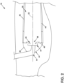
- FIG. 2 depicts a cross-section view of a combustor 36 suitable for use in the combustion section 14 of FIG. 1 .
- the combustor 36 can include an annular arrangement of fuel nozzle assemblies 38 for providing fuel to the combustor. It should be appreciated that the fuel nozzle assemblies 38 can be organized as in an annular arrangement including multiple fuel injectors.
- the combustor 36 can have a can, can-annular, or annular arrangement depending on the type of engine in which the combustor 36 is located.
- the combustor 36 can include an annular inner combustor liner 40 and an annular outer combustor liner 42, a dome assembly 44 including a dome 46 and a deflector 48, which collectively define a combustion chamber 50 about a longitudinal axis 52.
- At least one fuel injector 54 is fluidly coupled to the combustion chamber 50 to supply fuel to the combustor 36.
- the fuel injector 54 can be disposed within the dome assembly 44 upstream of a flare cone 56 to define a fuel outlet 58.
- a swirler can be provided at the fuel nozzle assembly 38 to swirl incoming air in proximity to fuel exiting the fuel injector 54 and provide a homogeneous mixture of air and fuel entering the combustor 36.
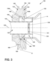
- FIG. 3 illustrates a fuel nozzle assembly 130, suitable for use in the combustor 36 as the fuel nozzle assembly 38, including a fuel nozzle 132 defining a longitudinal axis 128, and an annular swirler 134 circumscribing the fuel nozzle 132.
- the fuel nozzle 132 can define a fuel passage 136, with a nozzle cap 138 provided in the fuel passage 136 upstream of a nozzle tip 139, relative to the fuel direction.
- the nozzle cap 138 can include a set of openings 141 which may or may not impart a swirl or tangential component to the fuel emitted from the nozzle tip 139. As shown, the openings 141 are oriented tangentially, such that they appear to end within the cap 138, while it should be appreciated the openings 141 extend fully through the cap 138 such that fuel can pass through the cap 138 via the openings 141.
- the swirler 134 includes a forward wall 140, an aft wall 142, and a central wall 146 with a set of vanes 144 provided therein, including a primary set of vanes 144a and a secondary set of vanes 144b, extending between the forward wall 140 and the central wall 146, and between the aft wall 142 and the central wall 146, respectively.
- the vanes 144 impart a tangential swirl to the airflow passing through the swirler 134 before exhausting.
- the forward wall 140 and the central wall 146 can define a forward passage 148 and the central wall 146 and the aft wall 142 can define an aft passage 150.
- the primary set of vanes 144a can have a lesser swirl number compared to the secondary set of vanes 144b.
- Lower swirl from the primary set of vanes 144a achieves an increased axial velocity component along the fuel nozzle outer diameter to prevent flame holding.
- a higher swirl from the secondary set of vanes 144b achieves higher flow velocity on a diverging flare cone that prevents flame holding.
- the swirl from primary set of vanes 144a can be from 0.0 to 0.6 where swirl from the second set of vanes 144b can be from 0.0 to 1.5, while wider ranges are contemplated.
- a lip 152 extends in the downstream direction from the vanes 144 at the central wall 146 between the forward and aft passages 148, 150.
- the lip 152 extends in the radially inward direction, relative to the longitudinal extent of the fuel nozzle 132, and then curves, turning in the aft direction.
- the lip 152 provides a high velocity component along the fuel nozzle 132, which can reduce or eliminate flame holding and flashback along the fuel nozzle assembly.
- fuels with high burn speeds or temperatures, such as hydrogen compared to common fuel can be utilized, while current systems would have durability issues under those operating conditions. Utilizing a hydrogen fuel can provide for reducing or eliminating emissions, such as carbon emissions, while maintaining or improving engine efficiency.
- a purge opening 154 which can be arranged as a set of circumferentially-arranged openings in one non-limiting example, can extend through the swirler 134 and the forward wall 140 and fluidly couple to the swirler 134 through the forward wall 140.
- the purge opening 154 can be angled toward the fuel nozzle 132, while it is further contemplated that the purge openings 154 can include a tangential component, such that the purge airflow provided by the purge openings 154 can be similar to a swirling airflow provided from the vanes 144 of the swirler 134, which can reduce shear between the two airflows.
- the aft curved lip 152 can be positioned between the forward passage 148 and the aft passage 150, to provide for directing the airflow along the fuel nozzle 132 with a high velocity component.
- the curvature of the lip 152 provides for decreased wakes or smaller wake distances by utilizing the flow from the forward passage 148 to reduce or eliminate wake formed by the lip 152.
- a passage height H can be defined as the distance between the fuel nozzle 132 and the aft wall 142 of the swirler 134 downstream of the lip 152, where the cross-sectional area for the passage height H can be constant extending in the aft direction along the aft wall 142. Where the cross-sectional area defined by the passage height is non-constant, the passage height H can be defined as the smallest distance between the fuel nozzle 132 and the aft wall 142, downstream of the lip 152. In one example, the lip 152 can extend radially inward, toward and relative to the axial extent of the fuel nozzle 132.
- the curvature of the lip 152 can be defined. Specifically, the lip 152 can begin extending at a 0-degree angle, relative to a radial direction R defined by the axial extent of the fuel nozzle 132. The lip 152 can turn, curving from the axial extent toward the aft direction. Additionally, the lip 152 can be arranged at an incline relative to the fuel nozzle 132, defining a lip axis 168, which can define an angle 164 between 1-degree and 85-degrees relative to a radial axis R, while such a curvature would be 5-degrees offset from an axis parallel to the longitudinal axis 128.
- ranges are contemplated, such as any angle between 90-degrees and 0-degrees (zero degrees).
- the curvature can vary, such as varying in the circumferential direction, or in the radial direction along a circumferential axis, which can be aligned with or offset with the purge openings 154 in one non-limiting example. Such a variation can be +/- 5-degrees, for example, while other or greater ranges are contemplated.
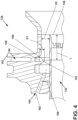
- FIG. 4 illustrates a lip height that can be defined as a first height H1 and a swirler passage height can be defined as a second height H2.
- the first height H1 can be defined as the radial distance between a trailing edge 158 of the vanes 144 and an aft end 160 of the lip 152, defined along a ray extending from the longitudinal axis 128 of FIG. 3 .
- the second height H2 can be defined as the radial distance between the fuel nozzle 132 and the aft wall 142.
- the first height H1 can be defined between -0.9H2 to 0.9H2.
- the first height H1 can be between 0.9 times the second height H2 with the lip 152 positioned radially exterior of the trailing edge 158 of the vanes 144, or can be 0.9 times the second height H2 with the lip 152 positioned radially interior of the trailing edge 158 of the vanes 144.
- the lip can extend radially inward from between 0.2H2 and 0.8H2, while additional or wider ranges are contemplated.
- a swirler passage length L can be defined as the axial distance between the aft end 160 of the lip 152 and a nozzle tip 156 of the fuel nozzle 132.
- the length L can be defined parallel to the fuel nozzle 132, for example.
- the lip 152 can be sized or arranged such that the swirler passage length L can be between one (1) to six (6) times H2, while other ranges or sizes are contemplated.
- the purge opening 154 can define a purge opening axis 162 as a centerline through the purge opening 154.
- the purge opening 154 can be arranged such that the purge axis 162 is defined at an angle 166 relative to the fuel nozzle 132, or the longitudinal axis 128 defined by the fuel nozzle 132 in FIG. 3 .
- the angle 166 can be between negative-ten (-10) degrees and sixty (60) degrees, where a negative angle represents the purge opening 154 oriented away from the fuel nozzle 132, and a positive angle represents the purge opening 154 oriented toward the fuel nozzle 132.
- Orienting the purge opening 154 toward the fuel nozzle 132 can impinge a purge flow along the fuel nozzle 132, which can provide a higher velocity component along the outer diameter of the fuel nozzle 132, which can reduce flashback or flame holding at the fuel nozzle 132.
- the axial position of the fuel nozzle 132 can be such that the purge opening 154 impinges upon the fuel nozzle 132, or such that the purge opening 154 impinges upon the fuel nozzle tip 156.
- an alternative fuel nozzle assembly 200 includes a fuel nozzle 202 and a swirler 204.
- the swirler 204 includes a forward wall 206 and an aft wall 208, with a set of vanes 210 extending between the forward wall 206 and the aft wall 208.
- a swirler lip 212 extends from the trailing edge 214 of the set of vanes 210.
- a purge opening 216 can extend axially, and can be arranged parallel to the fuel nozzle 202, for example. The purge opening 216 can be arranged forward of the swirler lip 212, such that there is no line-of-sight of the purge opening 216 when viewed axially into the fuel nozzle assembly 200 opposite of the flow direction.
- the purge opening 216 or an outlet thereof can be axially aligned and axially overlap with the swirler lip 212. Eliminating the direct line-of-sight for the purge opening 216 can reduce or eliminate flashback at the fuel nozzle assembly 200, or risk thereof to the purge openings 216.
- FIG. 6 shows another alternative fuel nozzle assembly 230 including a fuel nozzle 232 and a swirler 234.
- the swirler 234 includes a forward wall 236 and an aft wall 238, with a center wall 240 therebetween defining a primary swirler passage 242 and a secondary swirler passage 244.
- a set of primary vanes 246 is provided in the primary swirler passage 242, and a set of secondary vanes 248 is provided in the secondary swirler passage 244.
- An annular lip 250 extends from the center wall 240 at the sets of vanes 246, 248, curving or angled from a radial direction to an axial direction.
- a set of purge openings 252 are shaped into the swirler 234 and partially defined by the outer diameter of the fuel nozzle 232.
- the purge openings 252 can be formed as sets of discrete openings, which can include grooves or slots formed into the inner diameter wall of the swirler 234, extending parallel to the fuel nozzle 232.
- the cross-sectional shape for the purge openings 252, best seen in FIG. 7 taken across section VII-VII of FIG. 6 can be semicircular, while alternative shapes are contemplated, such as circular, elliptical, semielliptical, triangular, squared, rounded, or combinations thereof in non-limiting examples.
- an annular opening extending fully around the fuel nozzle 232 is contemplated.
- the annular shape of the fuel nozzle 232 can be appreciated as shown.
- a flow of air is provided through the swirler 234 to impart a swirl or tangential component to the flow of air in the primary and secondary swirler passages 242, 244.
- the purge openings 252 provide a high velocity along the outer diameter of the fuel nozzle 232, which can reduce or eliminate flame holding or flashback on the fuel nozzle 232.
- a higher tangential component in the secondary swirler passage 244 can reduce or eliminate flame holding on the flare cone 218.
- the purge openings 252 can be arranged tangentially, complementary or equivalent to the tangential swirl imparted by the primary swirler passage 242.
- another alternative fuel nozzle assembly 270 includes a fuel nozzle 272 and a swirler 274.
- the swirler 274 includes a forward wall 276, an aft wall 278, and a center wall 280 therebetween defining a primary swirler passage 282 and a secondary swirler passage 284.
- a first set of vanes 286 is provided in the primary swirler passage 282 and a second set of vanes 288 is provided in the secondary swirler passage 284.
- a set of purge openings 290 are circumferentially arranged about the swirler 274 forward of the forward wall 276.
- the purge openings 290 can couple to an annular groove 292 formed into the forward wall 276, which can be common to all purge openings 290 in the set of purge openings 290.
- the groove 292 can include a rounded profile, while any profile is contemplated, such as rounded, curved, linear, curvilinear, geometric, circular, elliptical, squared, or combinations thereof in non-limiting examples.
- the groove 292 can be shaped to define a converging cross-sectional area in the flow direction to provide an increased velocity component for the flow emitted from the groove 292, which can reduce flame holding or flashback at the fuel nozzle 272.
- the groove 292 can include a constant cross-section or a diverging cross-section.
- the purge openings 290 can be inclined, or angled toward the fuel nozzle 272, while other suitable arrangements are contemplated, such as a radially-angular component, an axially-angular component, a circumferentially-angular component, or combination thereof.
- the cross-sectional area can vary in the circumferential direction, which may or may not relate to the arrangement of the purge openings 290.
- the groove 292 can further provide for even spread of a purge flow before supply to the swirler 274, which can reduce shear turbulence generated from discrete purge opening outlets.
- FIG. 9 shows another alternative fuel nozzle assembly 300, which can be similar to that of FIG. 8 , except that an annular groove 302 can be fed from multiple purge openings 304, which can be in a stacked arrangement 310, stacked in a radial direction relative to a fuel nozzle 306 of the fuel nozzle assembly 300.
- purge openings 304 can provide a uniform supply of air to the annular groove 302, which can be utilized to provide circumferentially-uniform flow profiles to a swirler 308, while utilizing discrete purge openings 304.
- Discrete or complex geometries can provide for tailoring an air profile emitted from the purge openings to the swirler 308. Such geometries can be utilized to improve velocity along the fuel nozzle 306 to reduce flame holding on the nozzle tip, or improved swirl which can reduce flame holding on a flare cone or combustor liner.
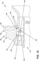
- FIG. 10 depicts yet another alternative fuel nozzle assembly 330 including a fuel nozzle 332 and a swirler 334.
- the swirler 334 includes a forward wall 336 and an aft wall 338, with a central wall 340 therebetween defining a first passage 342 and a second passage 344.
- a first set of vanes 346 is provided in the first passage 342 and a second set of vanes 348 is provided in the second passage 344.
- a lip 350 extends radially inward from the central wall 340 at a trailing edge 352 of the vanes 346, 348.
- the lip 350 includes a t-shaped profile, such that a first portion 354 of the lip 350 extends in the radial direction, which splits into a forward portion 356 and an aft portion 358 extending forward and aft from the first portion 354, respectively.
- the t-shape of the lip 350 defines a constant cross-sectional area defined in the radial direction from the forward and aft portions 356, 358 to the fuel nozzle 332.
- the constant cross-sectional area provides a higher axial velocity component along the outer diameter of the fuel nozzle 332, which can provide for reducing or eliminating flame holding or flashback at the fuel nozzle 332.
- fuels with higher burn temperature and higher burn speeds, or lighter weights relative to air or other fuels can provide for reducing or eliminating emissions, or improving efficiency without increasing emissions.
- hydrogen fuels or hydrogen-based fuels can be utilized, which can eliminate carbon emissions without negative impact to efficiency.
- Such fuels, including hydrogen require greater flame control, in order to prevent flame holding or flashback on the combustor hardware.
- the aspects described herein can increase combustor durability, while current combustors fail to provide durability to utilize such fuels.
Landscapes
- Engineering & Computer Science (AREA)
- Chemical & Material Sciences (AREA)
- Combustion & Propulsion (AREA)
- Mechanical Engineering (AREA)
- General Engineering & Computer Science (AREA)
- Spray-Type Burners (AREA)
- Nozzles For Spraying Of Liquid Fuel (AREA)
- Pre-Mixing And Non-Premixing Gas Burner (AREA)
- Gas Burners (AREA)
Claims (12)
- Turbinentriebwerk (10), umfassend:
einen Verdichterbereich (12), einen Verbrennungsbereich (14) und einen Turbinenbereich (16) in serieller Strömungsanordnung, wobei der Verbrennungsbereich (14) eine Brennstoffdüsenanordnung (130) einschließt, umfassend:eine Brennstoffdüse (132), die an einer Düsenspitze (139) endet, wobei die Brennstoffdüse (132) eine Längsachse (128) definiert und einen Brennstoffkanal (136) einschließt, wobei sich der Brennstoffkanal (136) entlang der Längsachse (128) erstreckt;einen Verwirbler (134), wobei der Verwirbler (134) ein ringförmiger Verwirbler ist, der die Brennstoffdüse (132) umgibt und einen Verwirblerkanal (126) definiert, und der eine vordere Wand (140), eine hintere Wand (142) und eine zwischen der vorderen Wand (140) und der hinteren Wand (142) vorgesehene Mittelwand (146) umfasst;einen Satz von Leitschaufeln (144), der innerhalb des Verwirblers (134) vorgesehen ist, wobei der Satz von Leitschaufeln (144) einen ersten Satz von Leitschaufeln (144a), der sich zwischen der Vorderwand (140) und der Mittelwand (146) erstreckt, und einen zweiten Satz von Leitschaufeln (144b), der sich zwischen der Mittelwand (146) und der Hinterwand (142) erstreckt, einschließt; undeine Lippe (152), die sich stromabwärts von dem Satz von Leitschaufeln (144) relativ zu einem Luftstrom durch den Verwirbler (134) erstreckt;wobei sich die Lippe (152) von der Mittelwand (146) aus erstreckt;wobei die Düsenspitze (139) hinter dem hinteren Ende (160) der Lippe (152) relativ zu der Längsachse angeordnet ist und der Verwirbelungskanal (126) sich zwischen dem hinteren Ende (160) der Lippe (152) und der Düsenspitze erstreckt; undwobei das hintere Ende (160) der Lippe (152) vor der hinteren Wand (142) relativ zu der Längsachse (128) positioniert ist;dadurch gekennzeichnet, dass der Brennstoffkanal (136) an der Düsenspitze (136) endet. - Turbinentriebwerk (10) nach Anspruch 1, wobei der erste Satz Leitschaufeln (144a) so angeordnet ist, dass er einen Wirbel zwischen 0,0 und 0,6 erzeugt, und der zweite Satz Leitschaufeln (144b) so angeordnet ist, dass er einen Wirbel zwischen 0,0 und 1,5 erzeugt.
- Turbinentriebwerk (10) nach einem der Ansprüche 1-2, wobei die Lippe (152) eine Lippenhöhe (H1) als radialen Abstand senkrecht zu der Längsachse (128) definiert, der sich von der Leitschaufelgruppe (144) bis zu einem Ende der Lippe (152) erstreckt.
- Turbinentriebwerk (10) nach Anspruch 3, wobei der Verwirbelungskanal (126) eine Verwirblerhöhe (H2) als radiale Länge zwischen der Kraftstoffdüse (132) und dem Verwirbler (134) senkrecht zu der Längsachse (128) definiert.
- Turbinentriebwerk (10) nach Anspruch 4, wobei die Lippenhöhe (H1) zwischen dem -0,9-fachen der Verwirblerhöhe (H2) und dem 0,9-fachen der Verwirblerhöhe (H2) liegt.
- Turbinentriebwerk (10) nach Anspruch 4, wobei eine Verwirblerkanallänge (L) als ein axialer Abstand zwischen der Lippe (152) und der Düsenspitze (156) definiert ist, und wobei die Verwirblerkanallänge (L) zwischen dem ein- bis sechsfachen der Verwirbelungshöhe (H2) liegt.
- Turbinentriebwerk (10) nach einem der Ansprüche 1 bis 6, wobei sich die Lippe (152) in einer Richtung nach hinten krümmt.
- Turbinentriebwerk (10) nach einem der Ansprüche 1 bis 7, wobei die Lippe (152) in einem Winkel (164) relativ zu der Längsachse (128) geneigt ist und wobei der Winkel (164) zwischen 1 Grad und 85 Grad liegt.
- Turbinentriebwerk (10) nach einem der Ansprüche 1 bis 8, wobei die Lippe (152) ein T-förmiges Profil aufweist.
- Turbinentriebwerk (10) nach einem der Ansprüche 1 bis 9, ferner umfassend eine Spülöffnung (154), die sich durch den Verwirbler (134) erstreckt.
- Turbinentriebwerk (10) nach Anspruch 10, wobei die Spülöffnung (154) in einem Winkel (166) relativ zu der Längsachse (128) angeordnet ist, wobei der Winkel (166) zwischen minus zehn Grad und sechzig Grad beträgt.
- Turbinentriebwerk (10) nach Anspruch 10, wobei die Spülöffnung (154) axial mit der Lippe (152) ausgerichtet ist.
Priority Applications (1)
| Application Number | Priority Date | Filing Date | Title |
|---|---|---|---|
| EP25152524.2A EP4517172A3 (de) | 2021-12-21 | 2022-07-21 | Brennstoffdüse und drallerzeuger |
Applications Claiming Priority (2)
| Application Number | Priority Date | Filing Date | Title |
|---|---|---|---|
| IN202111059696 | 2021-12-21 | ||
| US17/682,510 US12072099B2 (en) | 2021-12-21 | 2022-02-28 | Gas turbine fuel nozzle having a lip extending from the vanes of a swirler |
Related Child Applications (2)
| Application Number | Title | Priority Date | Filing Date |
|---|---|---|---|
| EP25152524.2A Division-Into EP4517172A3 (de) | 2021-12-21 | 2022-07-21 | Brennstoffdüse und drallerzeuger |
| EP25152524.2A Division EP4517172A3 (de) | 2021-12-21 | 2022-07-21 | Brennstoffdüse und drallerzeuger |
Publications (2)
| Publication Number | Publication Date |
|---|---|
| EP4202304A1 EP4202304A1 (de) | 2023-06-28 |
| EP4202304B1 true EP4202304B1 (de) | 2025-02-26 |
Family
ID=82656440
Family Applications (2)
| Application Number | Title | Priority Date | Filing Date |
|---|---|---|---|
| EP22186344.2A Active EP4202304B1 (de) | 2021-12-21 | 2022-07-21 | Turbinenmotor mit brennstoffdüse und verwirbler |
| EP25152524.2A Pending EP4517172A3 (de) | 2021-12-21 | 2022-07-21 | Brennstoffdüse und drallerzeuger |
Family Applications After (1)
| Application Number | Title | Priority Date | Filing Date |
|---|---|---|---|
| EP25152524.2A Pending EP4517172A3 (de) | 2021-12-21 | 2022-07-21 | Brennstoffdüse und drallerzeuger |
Country Status (3)
| Country | Link |
|---|---|
| US (2) | US12601485B2 (de) |
| EP (2) | EP4202304B1 (de) |
| CN (2) | CN116293792B (de) |
Families Citing this family (1)
| Publication number | Priority date | Publication date | Assignee | Title |
|---|---|---|---|---|
| EP4202304B1 (de) * | 2021-12-21 | 2025-02-26 | General Electric Company | Turbinenmotor mit brennstoffdüse und verwirbler |
Citations (2)
| Publication number | Priority date | Publication date | Assignee | Title |
|---|---|---|---|---|
| US20120266602A1 (en) * | 2011-04-22 | 2012-10-25 | General Electric Company | Aerodynamic Fuel Nozzle |
| US20160265779A1 (en) * | 2015-03-11 | 2016-09-15 | General Electric Company | Twin radial splitter-chevron mixer with converging throat |
Family Cites Families (77)
| Publication number | Priority date | Publication date | Assignee | Title |
|---|---|---|---|---|
| US3946552A (en) | 1973-09-10 | 1976-03-30 | General Electric Company | Fuel injection apparatus |
| US4198815A (en) * | 1975-12-24 | 1980-04-22 | General Electric Company | Central injection fuel carburetor |
| GB9023004D0 (en) | 1990-10-23 | 1990-12-05 | Rolls Royce Plc | A gas turbine engine combustion chamber and a method of operating a gas turbine engine combustion chamber |
| DE4110507C2 (de) | 1991-03-30 | 1994-04-07 | Mtu Muenchen Gmbh | Brenner für Gasturbinentriebwerke mit mindestens einer für die Zufuhr von Verbrennungsluft lastabhängig regulierbaren Dralleinrichtung |
| US5505045A (en) | 1992-11-09 | 1996-04-09 | Fuel Systems Textron, Inc. | Fuel injector assembly with first and second fuel injectors and inner, outer, and intermediate air discharge chambers |
| GB2272756B (en) * | 1992-11-24 | 1995-05-31 | Rolls Royce Plc | Fuel injection apparatus |
| DE19627760C2 (de) | 1996-07-10 | 2001-05-03 | Mtu Aero Engines Gmbh | Brenner mit Zerstäuberdüse |
| FR2752917B1 (fr) | 1996-09-05 | 1998-10-02 | Snecma | Systeme d'injection a degre d'homogeneisation avancee |
| FR2753779B1 (fr) | 1996-09-26 | 1998-10-16 | Systeme d'injection aerodynamique d'un melange air carburant | |
| US5916142A (en) | 1996-10-21 | 1999-06-29 | General Electric Company | Self-aligning swirler with ball joint |
| US5826423A (en) | 1996-11-13 | 1998-10-27 | Solar Turbines Incorporated | Dual fuel injection method and apparatus with multiple air blast liquid fuel atomizers |
| US5966937A (en) | 1997-10-09 | 1999-10-19 | United Technologies Corporation | Radial inlet swirler with twisted vanes for fuel injector |
| US6550251B1 (en) | 1997-12-18 | 2003-04-22 | General Electric Company | Venturiless swirl cup |
| US6212870B1 (en) | 1998-09-22 | 2001-04-10 | General Electric Company | Self fixturing combustor dome assembly |
| US6883332B2 (en) | 1999-05-07 | 2005-04-26 | Parker-Hannifin Corporation | Fuel nozzle for turbine combustion engines having aerodynamic turning vanes |
| US6279323B1 (en) | 1999-11-01 | 2001-08-28 | General Electric Company | Low emissions combustor |
| US6314739B1 (en) | 2000-01-13 | 2001-11-13 | General Electric Company | Brazeless combustor dome assembly |
| US6427435B1 (en) | 2000-05-20 | 2002-08-06 | General Electric Company | Retainer segment for swirler assembly |
| US6502400B1 (en) | 2000-05-20 | 2003-01-07 | General Electric Company | Combustor dome assembly and method of assembling the same |
| US6367262B1 (en) | 2000-09-29 | 2002-04-09 | General Electric Company | Multiple annular swirler |
| US6442940B1 (en) | 2001-04-27 | 2002-09-03 | General Electric Company | Gas-turbine air-swirler attached to dome and combustor in single brazing operation |
| FR2827367B1 (fr) | 2001-07-16 | 2003-10-17 | Snecma Moteurs | Systeme d'injection aeromecanique a vrille primaire anti-retour |
| US6581386B2 (en) | 2001-09-29 | 2003-06-24 | General Electric Company | Threaded combustor baffle |
| FR2832493B1 (fr) | 2001-11-21 | 2004-07-09 | Snecma Moteurs | Systeme d'injection multi-etages d'un melange air/carburant dans une chambre de combustion de turbomachine |
| GB0219458D0 (en) * | 2002-08-21 | 2002-09-25 | Rolls Royce Plc | Fuel injection apparatus |
| US6834505B2 (en) | 2002-10-07 | 2004-12-28 | General Electric Company | Hybrid swirler |
| US6986255B2 (en) | 2002-10-24 | 2006-01-17 | Rolls-Royce Plc | Piloted airblast lean direct fuel injector with modified air splitter |
| US6932093B2 (en) | 2003-02-24 | 2005-08-23 | General Electric Company | Methods and apparatus for washing gas turbine engine combustors |
| US7062920B2 (en) * | 2003-08-11 | 2006-06-20 | General Electric Company | Combustor dome assembly of a gas turbine engine having a free floating swirler |
| US7104066B2 (en) | 2003-08-19 | 2006-09-12 | General Electric Company | Combuster swirler assembly |
| FR2859272B1 (fr) | 2003-09-02 | 2005-10-14 | Snecma Moteurs | Systeme d'injection air/carburant, dans une chambre de combustion de turbomachine, ayant des moyens de generation de plasmas froids |
| US7334410B2 (en) | 2004-04-07 | 2008-02-26 | United Technologies Corporation | Swirler |
| US20050229600A1 (en) | 2004-04-16 | 2005-10-20 | Kastrup David A | Methods and apparatus for fabricating gas turbine engine combustors |
| US7013649B2 (en) | 2004-05-25 | 2006-03-21 | General Electric Company | Gas turbine engine combustor mixer |
| US8348180B2 (en) | 2004-06-09 | 2013-01-08 | Delavan Inc | Conical swirler for fuel injectors and combustor domes and methods of manufacturing the same |
| US7596949B2 (en) | 2006-02-23 | 2009-10-06 | General Electric Company | Method and apparatus for heat shielding gas turbine engines |
| FR2901349B1 (fr) | 2006-05-19 | 2008-09-05 | Snecma Sa | Chambre de combustion d'une turbomachine |
| US7870736B2 (en) | 2006-06-01 | 2011-01-18 | Virginia Tech Intellectual Properties, Inc. | Premixing injector for gas turbine engines |
| US7654091B2 (en) | 2006-08-30 | 2010-02-02 | General Electric Company | Method and apparatus for cooling gas turbine engine combustors |
| FR2918716B1 (fr) * | 2007-07-12 | 2014-02-28 | Snecma | Optimisation d'un film anti-coke dans un systeme d'injection |
| GB201112434D0 (en) * | 2011-07-20 | 2011-08-31 | Rolls Royce Plc | A fuel injector |
| FR2988813B1 (fr) | 2012-03-29 | 2017-09-01 | Snecma | Dispositif d'injection d'un melange d'air et de carburant dans une chambre de combustion de turbomachine |
| US9404656B2 (en) | 2012-12-17 | 2016-08-02 | United Technologies Corporation | Oblong swirler assembly for combustors |
| US10794596B2 (en) | 2013-08-30 | 2020-10-06 | Raytheon Technologies Corporation | Dual fuel nozzle with liquid filming atomization for a gas turbine engine |
| US10731861B2 (en) | 2013-11-18 | 2020-08-04 | Raytheon Technologies Corporation | Dual fuel nozzle with concentric fuel passages for a gas turbine engine |
| FR3029608B1 (fr) | 2014-12-03 | 2017-01-13 | Snecma | Couronne d'admission d'air pour systeme d'injection de chambre de combustion de turbomachine et procede d'atomisation de carburant dans un systeme d'injection comprenant ladite couronne d'admission d'air |
| US10060628B2 (en) * | 2015-03-26 | 2018-08-28 | General Electric Company | Systems and methods for creating a seal about a liquid fuel injector in a gas turbine engine |
| US10132500B2 (en) | 2015-10-16 | 2018-11-20 | Delavan Inc. | Airblast injectors |
| US10234142B2 (en) | 2016-04-15 | 2019-03-19 | Solar Turbines Incorporated | Fuel delivery methods in combustion engine using wide range of gaseous fuels |
| US10344981B2 (en) | 2016-12-16 | 2019-07-09 | Delavan Inc. | Staged dual fuel radial nozzle with radial liquid fuel distributor |
| US10954859B2 (en) | 2017-07-25 | 2021-03-23 | Raytheon Technologies Corporation | Low emissions combustor assembly for gas turbine engine |
| GB201716585D0 (en) | 2017-09-08 | 2017-11-22 | Rolls Royce Plc | Spray nozzle |
| US10801726B2 (en) * | 2017-09-21 | 2020-10-13 | General Electric Company | Combustor mixer purge cooling structure |
| US10830446B2 (en) | 2017-12-15 | 2020-11-10 | Delavan Inc. | Fuel injector assemblies |
| CN108224478B (zh) * | 2017-12-27 | 2020-09-22 | 中国航发四川燃气涡轮研究院 | 抑制文氏管积碳的高温升燃烧室头部 |
| FR3082284B1 (fr) | 2018-06-07 | 2020-12-11 | Safran Aircraft Engines | Chambre de combustion pour une turbomachine |
| US11226101B2 (en) * | 2019-02-01 | 2022-01-18 | General Electric Company | Combustor swirler |
| US11802693B2 (en) | 2021-04-16 | 2023-10-31 | General Electric Company | Combustor swirl vane apparatus |
| US11598526B2 (en) * | 2021-04-16 | 2023-03-07 | General Electric Company | Combustor swirl vane apparatus |
| US11384937B1 (en) | 2021-05-12 | 2022-07-12 | General Electric Company | Swirler with integrated damper |
| US11428411B1 (en) | 2021-05-18 | 2022-08-30 | General Electric Company | Swirler with rifled venturi for dynamics mitigation |
| CN115523068B (zh) * | 2021-06-24 | 2025-07-18 | 通用电气公司 | 旋流器套圈组件 |
| CN115711176B (zh) * | 2021-08-23 | 2025-09-05 | 通用电气公司 | 具有集成喇叭形旋流器的圆顶 |
| GB2611115B (en) * | 2021-09-23 | 2024-10-09 | Gen Electric | Floating primary vane swirler |
| CN116136308B (zh) * | 2021-11-16 | 2025-09-26 | 通用电气公司 | 具有压降吹扫通道的旋流器套圈板 |
| US12072099B2 (en) * | 2021-12-21 | 2024-08-27 | General Electric Company | Gas turbine fuel nozzle having a lip extending from the vanes of a swirler |
| US20230194095A1 (en) | 2021-12-21 | 2023-06-22 | General Electric Company | Fuel nozzle and swirler |
| EP4202304B1 (de) * | 2021-12-21 | 2025-02-26 | General Electric Company | Turbinenmotor mit brennstoffdüse und verwirbler |
| EP4202305B1 (de) | 2021-12-21 | 2025-09-24 | General Electric Company | Gasturbinenmotor |
| US11725819B2 (en) | 2021-12-21 | 2023-08-15 | General Electric Company | Gas turbine fuel nozzle having a fuel passage within a swirler |
| US12092332B2 (en) * | 2021-12-29 | 2024-09-17 | General Electric Company | Fuel nozzle and swirler |
| US12359813B2 (en) * | 2021-12-29 | 2025-07-15 | General Electric Company | Engine fuel nozzle and swirler |
| US12123592B2 (en) * | 2022-01-12 | 2024-10-22 | General Electric Company | Fuel nozzle and swirler |
| US11994295B2 (en) * | 2022-02-18 | 2024-05-28 | General Electric Company | Multi pressure drop swirler ferrule plate |
| US12038176B2 (en) * | 2022-02-18 | 2024-07-16 | General Electric Company | Coupling a fuel nozzle purge flow directly to a swirler |
| US12092324B2 (en) * | 2022-03-17 | 2024-09-17 | General Electric Company | Flare cone for a mixer assembly of a gas turbine combustor |
| US20240288169A1 (en) * | 2023-02-27 | 2024-08-29 | Raytheon Technologies Corporation | Fuel injector air swirler structure with canted flow guide surface |
-
2022
- 2022-07-21 EP EP22186344.2A patent/EP4202304B1/de active Active
- 2022-07-21 EP EP25152524.2A patent/EP4517172A3/de active Pending
- 2022-08-31 CN CN202211055027.1A patent/CN116293792B/zh active Active
- 2022-08-31 CN CN202511750237.6A patent/CN121229975A/zh active Pending
-
2024
- 2024-03-22 US US18/613,824 patent/US12601485B2/en active Active
-
2025
- 2025-10-24 US US19/368,315 patent/US20260049718A1/en active Pending
Patent Citations (2)
| Publication number | Priority date | Publication date | Assignee | Title |
|---|---|---|---|---|
| US20120266602A1 (en) * | 2011-04-22 | 2012-10-25 | General Electric Company | Aerodynamic Fuel Nozzle |
| US20160265779A1 (en) * | 2015-03-11 | 2016-09-15 | General Electric Company | Twin radial splitter-chevron mixer with converging throat |
Also Published As
| Publication number | Publication date |
|---|---|
| US20250251131A1 (en) | 2025-08-07 |
| CN116293792A (zh) | 2023-06-23 |
| CN116293792B (zh) | 2025-12-16 |
| CN121229975A (zh) | 2025-12-30 |
| US20260049718A1 (en) | 2026-02-19 |
| EP4202304A1 (de) | 2023-06-28 |
| EP4517172A2 (de) | 2025-03-05 |
| US12601485B2 (en) | 2026-04-14 |
| EP4517172A3 (de) | 2025-03-26 |
Similar Documents
| Publication | Publication Date | Title |
|---|---|---|
| US12359813B2 (en) | Engine fuel nozzle and swirler | |
| US12085281B2 (en) | Fuel nozzle and swirler | |
| US12072099B2 (en) | Gas turbine fuel nozzle having a lip extending from the vanes of a swirler | |
| US11725819B2 (en) | Gas turbine fuel nozzle having a fuel passage within a swirler | |
| EP4202303B1 (de) | Brennstoffdüse und verwirbler | |
| US20230194095A1 (en) | Fuel nozzle and swirler | |
| US12228282B2 (en) | Gas turbine fuel nozzle having an inner air passage and plural outer fuel passages | |
| US11906165B2 (en) | Gas turbine nozzle having an inner air swirler passage and plural exterior fuel passages | |
| US20250035311A1 (en) | Fuel nozzle and swirler | |
| US20260049718A1 (en) | Turbine engine with fuel nozzle | |
| EP3889509B1 (de) | Brennstoffdüse mit verbesserter drallschaufelstruktur | |
| CN116412415B (en) | Engine fuel nozzle and swirler | |
| US20260043353A1 (en) | Turbine engine fuel nozzle and swirler | |
| EP4675176A1 (de) | Turbinenmotor mit einem kraftstoffinjektor | |
| CN121761337A (zh) | 用于涡轮发动机的燃料注入器 |
Legal Events
| Date | Code | Title | Description |
|---|---|---|---|
| PUAI | Public reference made under article 153(3) epc to a published international application that has entered the european phase |
Free format text: ORIGINAL CODE: 0009012 |
|
| STAA | Information on the status of an ep patent application or granted ep patent |
Free format text: STATUS: THE APPLICATION HAS BEEN PUBLISHED |
|
| AK | Designated contracting states |
Kind code of ref document: A1 Designated state(s): AL AT BE BG CH CY CZ DE DK EE ES FI FR GB GR HR HU IE IS IT LI LT LU LV MC MK MT NL NO PL PT RO RS SE SI SK SM TR |
|
| STAA | Information on the status of an ep patent application or granted ep patent |
Free format text: STATUS: REQUEST FOR EXAMINATION WAS MADE |
|
| 17P | Request for examination filed |
Effective date: 20231204 |
|
| RBV | Designated contracting states (corrected) |
Designated state(s): AL AT BE BG CH CY CZ DE DK EE ES FI FR GB GR HR HU IE IS IT LI LT LU LV MC MK MT NL NO PL PT RO RS SE SI SK SM TR |
|
| STAA | Information on the status of an ep patent application or granted ep patent |
Free format text: STATUS: EXAMINATION IS IN PROGRESS |
|
| 17Q | First examination report despatched |
Effective date: 20240222 |
|
| GRAP | Despatch of communication of intention to grant a patent |
Free format text: ORIGINAL CODE: EPIDOSNIGR1 |
|
| STAA | Information on the status of an ep patent application or granted ep patent |
Free format text: STATUS: GRANT OF PATENT IS INTENDED |
|
| INTG | Intention to grant announced |
Effective date: 20240919 |
|
| GRAS | Grant fee paid |
Free format text: ORIGINAL CODE: EPIDOSNIGR3 |
|
| GRAA | (expected) grant |
Free format text: ORIGINAL CODE: 0009210 |
|
| STAA | Information on the status of an ep patent application or granted ep patent |
Free format text: STATUS: THE PATENT HAS BEEN GRANTED |
|
| RAP3 | Party data changed (applicant data changed or rights of an application transferred) |
Owner name: GENERAL ELECTRIC COMPANY |
|
| AK | Designated contracting states |
Kind code of ref document: B1 Designated state(s): AL AT BE BG CH CY CZ DE DK EE ES FI FR GB GR HR HU IE IS IT LI LT LU LV MC MK MT NL NO PL PT RO RS SE SI SK SM TR |
|
| P01 | Opt-out of the competence of the unified patent court (upc) registered |
Free format text: CASE NUMBER: APP_3641/2025 Effective date: 20250122 |
|
| REG | Reference to a national code |
Ref country code: GB Ref legal event code: FG4D |
|
| REG | Reference to a national code |
Ref country code: CH Ref legal event code: EP |
|
| REG | Reference to a national code |
Ref country code: DE Ref legal event code: R096 Ref document number: 602022011026 Country of ref document: DE |
|
| REG | Reference to a national code |
Ref country code: IE Ref legal event code: FG4D |
|
| REG | Reference to a national code |
Ref country code: NL Ref legal event code: MP Effective date: 20250226 |
|
| PG25 | Lapsed in a contracting state [announced via postgrant information from national office to epo] |
Ref country code: RS Free format text: LAPSE BECAUSE OF FAILURE TO SUBMIT A TRANSLATION OF THE DESCRIPTION OR TO PAY THE FEE WITHIN THE PRESCRIBED TIME-LIMIT Effective date: 20250526 |
|
| PG25 | Lapsed in a contracting state [announced via postgrant information from national office to epo] |
Ref country code: FI Free format text: LAPSE BECAUSE OF FAILURE TO SUBMIT A TRANSLATION OF THE DESCRIPTION OR TO PAY THE FEE WITHIN THE PRESCRIBED TIME-LIMIT Effective date: 20250226 |
|
| PG25 | Lapsed in a contracting state [announced via postgrant information from national office to epo] |
Ref country code: PL Free format text: LAPSE BECAUSE OF FAILURE TO SUBMIT A TRANSLATION OF THE DESCRIPTION OR TO PAY THE FEE WITHIN THE PRESCRIBED TIME-LIMIT Effective date: 20250226 |
|
| PG25 | Lapsed in a contracting state [announced via postgrant information from national office to epo] |
Ref country code: ES Free format text: LAPSE BECAUSE OF FAILURE TO SUBMIT A TRANSLATION OF THE DESCRIPTION OR TO PAY THE FEE WITHIN THE PRESCRIBED TIME-LIMIT Effective date: 20250226 |
|
| REG | Reference to a national code |
Ref country code: LT Ref legal event code: MG9D |
|
| PG25 | Lapsed in a contracting state [announced via postgrant information from national office to epo] |
Ref country code: NO Free format text: LAPSE BECAUSE OF FAILURE TO SUBMIT A TRANSLATION OF THE DESCRIPTION OR TO PAY THE FEE WITHIN THE PRESCRIBED TIME-LIMIT Effective date: 20250526 Ref country code: IS Free format text: LAPSE BECAUSE OF FAILURE TO SUBMIT A TRANSLATION OF THE DESCRIPTION OR TO PAY THE FEE WITHIN THE PRESCRIBED TIME-LIMIT Effective date: 20250626 |
|
| PG25 | Lapsed in a contracting state [announced via postgrant information from national office to epo] |
Ref country code: NL Free format text: LAPSE BECAUSE OF FAILURE TO SUBMIT A TRANSLATION OF THE DESCRIPTION OR TO PAY THE FEE WITHIN THE PRESCRIBED TIME-LIMIT Effective date: 20250226 |
|
| PG25 | Lapsed in a contracting state [announced via postgrant information from national office to epo] |
Ref country code: HR Free format text: LAPSE BECAUSE OF FAILURE TO SUBMIT A TRANSLATION OF THE DESCRIPTION OR TO PAY THE FEE WITHIN THE PRESCRIBED TIME-LIMIT Effective date: 20250226 |
|
| PG25 | Lapsed in a contracting state [announced via postgrant information from national office to epo] |
Ref country code: PT Free format text: LAPSE BECAUSE OF FAILURE TO SUBMIT A TRANSLATION OF THE DESCRIPTION OR TO PAY THE FEE WITHIN THE PRESCRIBED TIME-LIMIT Effective date: 20250626 Ref country code: LV Free format text: LAPSE BECAUSE OF FAILURE TO SUBMIT A TRANSLATION OF THE DESCRIPTION OR TO PAY THE FEE WITHIN THE PRESCRIBED TIME-LIMIT Effective date: 20250226 |
|
| PGFP | Annual fee paid to national office [announced via postgrant information from national office to epo] |
Ref country code: FR Payment date: 20250620 Year of fee payment: 4 |
|
| PG25 | Lapsed in a contracting state [announced via postgrant information from national office to epo] |
Ref country code: GR Free format text: LAPSE BECAUSE OF FAILURE TO SUBMIT A TRANSLATION OF THE DESCRIPTION OR TO PAY THE FEE WITHIN THE PRESCRIBED TIME-LIMIT Effective date: 20250527 Ref country code: BG Free format text: LAPSE BECAUSE OF FAILURE TO SUBMIT A TRANSLATION OF THE DESCRIPTION OR TO PAY THE FEE WITHIN THE PRESCRIBED TIME-LIMIT Effective date: 20250226 |
|
| REG | Reference to a national code |
Ref country code: AT Ref legal event code: MK05 Ref document number: 1770963 Country of ref document: AT Kind code of ref document: T Effective date: 20250226 |
|
| PG25 | Lapsed in a contracting state [announced via postgrant information from national office to epo] |
Ref country code: SE Free format text: LAPSE BECAUSE OF FAILURE TO SUBMIT A TRANSLATION OF THE DESCRIPTION OR TO PAY THE FEE WITHIN THE PRESCRIBED TIME-LIMIT Effective date: 20250226 |
|
| PG25 | Lapsed in a contracting state [announced via postgrant information from national office to epo] |
Ref country code: SM Free format text: LAPSE BECAUSE OF FAILURE TO SUBMIT A TRANSLATION OF THE DESCRIPTION OR TO PAY THE FEE WITHIN THE PRESCRIBED TIME-LIMIT Effective date: 20250226 |
|
| PG25 | Lapsed in a contracting state [announced via postgrant information from national office to epo] |
Ref country code: DK Free format text: LAPSE BECAUSE OF FAILURE TO SUBMIT A TRANSLATION OF THE DESCRIPTION OR TO PAY THE FEE WITHIN THE PRESCRIBED TIME-LIMIT Effective date: 20250226 |
|
| PGFP | Annual fee paid to national office [announced via postgrant information from national office to epo] |
Ref country code: DE Payment date: 20250620 Year of fee payment: 4 |
|
| PG25 | Lapsed in a contracting state [announced via postgrant information from national office to epo] |
Ref country code: IT Free format text: LAPSE BECAUSE OF FAILURE TO SUBMIT A TRANSLATION OF THE DESCRIPTION OR TO PAY THE FEE WITHIN THE PRESCRIBED TIME-LIMIT Effective date: 20250226 |
|
| PG25 | Lapsed in a contracting state [announced via postgrant information from national office to epo] |
Ref country code: AT Free format text: LAPSE BECAUSE OF FAILURE TO SUBMIT A TRANSLATION OF THE DESCRIPTION OR TO PAY THE FEE WITHIN THE PRESCRIBED TIME-LIMIT Effective date: 20250226 |
|
| PG25 | Lapsed in a contracting state [announced via postgrant information from national office to epo] |
Ref country code: EE Free format text: LAPSE BECAUSE OF FAILURE TO SUBMIT A TRANSLATION OF THE DESCRIPTION OR TO PAY THE FEE WITHIN THE PRESCRIBED TIME-LIMIT Effective date: 20250226 Ref country code: CZ Free format text: LAPSE BECAUSE OF FAILURE TO SUBMIT A TRANSLATION OF THE DESCRIPTION OR TO PAY THE FEE WITHIN THE PRESCRIBED TIME-LIMIT Effective date: 20250226 |
|
| PG25 | Lapsed in a contracting state [announced via postgrant information from national office to epo] |
Ref country code: RO Free format text: LAPSE BECAUSE OF FAILURE TO SUBMIT A TRANSLATION OF THE DESCRIPTION OR TO PAY THE FEE WITHIN THE PRESCRIBED TIME-LIMIT Effective date: 20250226 |
|
| PG25 | Lapsed in a contracting state [announced via postgrant information from national office to epo] |
Ref country code: SK Free format text: LAPSE BECAUSE OF FAILURE TO SUBMIT A TRANSLATION OF THE DESCRIPTION OR TO PAY THE FEE WITHIN THE PRESCRIBED TIME-LIMIT Effective date: 20250226 |
|
| REG | Reference to a national code |
Ref country code: DE Ref legal event code: R097 Ref document number: 602022011026 Country of ref document: DE |
|
| PLBE | No opposition filed within time limit |
Free format text: ORIGINAL CODE: 0009261 |
|
| STAA | Information on the status of an ep patent application or granted ep patent |
Free format text: STATUS: NO OPPOSITION FILED WITHIN TIME LIMIT |
|
| REG | Reference to a national code |
Ref country code: CH Ref legal event code: L10 Free format text: ST27 STATUS EVENT CODE: U-0-0-L10-L00 (AS PROVIDED BY THE NATIONAL OFFICE) Effective date: 20260107 |
|
| 26N | No opposition filed |
Effective date: 20251127 |
|
| REG | Reference to a national code |
Ref country code: CH Ref legal event code: H13 Free format text: ST27 STATUS EVENT CODE: U-0-0-H10-H13 (AS PROVIDED BY THE NATIONAL OFFICE) Effective date: 20260224 |
|
| PG25 | Lapsed in a contracting state [announced via postgrant information from national office to epo] |
Ref country code: LU Free format text: LAPSE BECAUSE OF NON-PAYMENT OF DUE FEES Effective date: 20250721 |
|
| REG | Reference to a national code |
Ref country code: BE Ref legal event code: MM Effective date: 20250731 |
|
| PG25 | Lapsed in a contracting state [announced via postgrant information from national office to epo] |
Ref country code: BE Free format text: LAPSE BECAUSE OF NON-PAYMENT OF DUE FEES Effective date: 20250731 |
|
| PG25 | Lapsed in a contracting state [announced via postgrant information from national office to epo] |
Ref country code: CH Free format text: LAPSE BECAUSE OF NON-PAYMENT OF DUE FEES Effective date: 20250731 |