EP4202575B1 - Sympathique uhr und pendel, die eine sympathique uhreneinheit bilden, und verfahren zum einstellen der uhr der genannten sympathique uhreneinheit - Google Patents
Sympathique uhr und pendel, die eine sympathique uhreneinheit bilden, und verfahren zum einstellen der uhr der genannten sympathique uhreneinheit Download PDFInfo
- Publication number
- EP4202575B1 EP4202575B1 EP21217368.6A EP21217368A EP4202575B1 EP 4202575 B1 EP4202575 B1 EP 4202575B1 EP 21217368 A EP21217368 A EP 21217368A EP 4202575 B1 EP4202575 B1 EP 4202575B1
- Authority
- EP
- European Patent Office
- Prior art keywords
- watch
- actuator
- clock
- lever
- display
- Prior art date
- Legal status (The legal status is an assumption and is not a legal conclusion. Google has not performed a legal analysis and makes no representation as to the accuracy of the status listed.)
- Active
Links
Images


Classifications
-
- G—PHYSICS
- G04—HOROLOGY
- G04B—MECHANICALLY-DRIVEN CLOCKS OR WATCHES; MECHANICAL PARTS OF CLOCKS OR WATCHES IN GENERAL; TIME PIECES USING THE POSITION OF THE SUN, MOON OR STARS
- G04B5/00—Automatic winding up
-
- G—PHYSICS
- G04—HOROLOGY
- G04B—MECHANICALLY-DRIVEN CLOCKS OR WATCHES; MECHANICAL PARTS OF CLOCKS OR WATCHES IN GENERAL; TIME PIECES USING THE POSITION OF THE SUN, MOON OR STARS
- G04B27/00—Mechanical devices for setting the time indicating means
- G04B27/007—Mechanical devices for setting the time indicating means otherwise than manually
-
- G—PHYSICS
- G04—HOROLOGY
- G04B—MECHANICALLY-DRIVEN CLOCKS OR WATCHES; MECHANICAL PARTS OF CLOCKS OR WATCHES IN GENERAL; TIME PIECES USING THE POSITION OF THE SUN, MOON OR STARS
- G04B13/00—Gearwork
-
- G—PHYSICS
- G04—HOROLOGY
- G04B—MECHANICALLY-DRIVEN CLOCKS OR WATCHES; MECHANICAL PARTS OF CLOCKS OR WATCHES IN GENERAL; TIME PIECES USING THE POSITION OF THE SUN, MOON OR STARS
- G04B27/00—Mechanical devices for setting the time indicating means
- G04B27/001—Internal gear therefor, e.g. for setting the second hand or for setting several clockworks
-
- G—PHYSICS
- G04—HOROLOGY
- G04B—MECHANICALLY-DRIVEN CLOCKS OR WATCHES; MECHANICAL PARTS OF CLOCKS OR WATCHES IN GENERAL; TIME PIECES USING THE POSITION OF THE SUN, MOON OR STARS
- G04B35/00—Adjusting the gear train, e.g. the backlash of the arbors, depth of meshing of the gears
-
- G—PHYSICS
- G04—HOROLOGY
- G04D—APPARATUS OR TOOLS SPECIALLY DESIGNED FOR MAKING OR MAINTAINING CLOCKS OR WATCHES
- G04D7/00—Measuring, counting, calibrating, testing or regulating apparatus
- G04D7/006—Testing apparatus for complete clockworks with regard to external influences or general good working
- G04D7/009—Testing apparatus for complete clockworks with regard to external influences or general good working with regard to the functioning of the automatic winding-up device
Definitions
- the invention concerns the very particular field of sympathetic clocks and watches.
- the invention relates more particularly to a sympathetic watch and clock forming a sympathetic timepiece assembly, and to a method of setting the time of the watch of said sympathetic timepiece assembly.
- the document EP 3945374 discloses a sympathetic pendulum cooperating with a watch which comprises a zero-reset mechanism, which is arranged to return at least one display of the watch to a reference position.
- the invention solves the above-mentioned drawbacks.
- the present invention relates to a sympathetic watch intended to cooperate with a sympathetic pendulum, comprising a watch movement to which at least one display of a time value is connected, a clutch mechanism making it possible to separate said at least one display and the going train, and a zero-reset mechanism intended to move said at least one watch display to a predetermined reference position.
- the watch comprises a first and a second actuator respectively intended to cooperate with a first and a second clock actuator, said first actuator of the watch capable of occupying at least three successive distinct positions so as to act on the clutch mechanism and on the zero-reset mechanism, said second actuator of the watch being capable of occupying two extreme positions alternately in order to act on said at least one display by means of a time-setting mechanism, only when the first actuator occupies one of its successive distinct positions.
- the watch is capable of being indexed step by step, at any time.
- the invention may further comprise one or more of the following features, taken alone or in any technically possible combination.
- the first actuator is configured to act on the stop mechanism of the watch resonator in two successive distinct positions.
- the first actuator of the watch is fixed in the watch case so as to ensure its water and air tightness.
- the transmission lever is arranged in the watch movement.
- the movement of the first actuator transmits, through a single lever, forces to the clutch mechanism, the resonator stop mechanism and the reset mechanism.
- the watch movement has a simple design, which in particular increases its reliability.
- the first actuator of the watch is configured to act on the clutch mechanism, on the stop mechanism and on the reset mechanism by means of a transmission lever to which it is connected, said transmission lever being configured to concomitantly actuate the clutch mechanism and the reset mechanism.
- the transmission lever extends between a first end of said lever at which it is rotatable and a second end comprising a protrusion by which said transmission lever cooperates with the reset mechanism, with the clutch mechanism and with the stop mechanism.
- the transmission lever may be arranged to be slidably movable.
- the transmission lever is subjected to a return force by a lever spring tending to move it into an initial position in which it drives the reset mechanism into an inactive position, the clutch mechanism into a clutch position and the stop mechanism into a position in which it releases the resonator.
- the watch when the watch is removed from a receptacle of the clock, the watch can resume normal operation on the one hand, and on the other hand the cooperation between the watch and the clock is interrupted without risk of damaging said watch or said clock.
- the clutch mechanism comprises two arms forming a clamp, and a friction spring tending to move the finishing gear into engagement with the display gear.
- the arms are biased by a clutch spring toward a clutch position and are configured so that when the first actuator occupies one of its positions, called “first position", they are driven against the clutch spring, in a disengaged position in which they oppose the action of the clutch spring and the friction spring in order to move said finishing gear away from the display gear.
- the arms cooperate with each other at an interface zone by which one of the arms, called the “first arm”, is able to force the other arm, called the “second arm”, to move towards the clutch position under the effect of the return force generated by the clutch spring, and by which the second arm is able to transmit to the first arm a force to which it is subjected by the transmission lever when the first actuator occupies its first position, this force moving said arms into the disengaged position.
- the reset mechanism comprises at least one heart cam integral in rotation with the display of a time value and at least one hammer arranged to cooperate in support with said at least one heart cam under the action of a hammer spring, so as to occupy an active position and constrain in rotation said heart cam until it is in support against its smallest radius, when the first actuator occupies one of its positions, called “first position", the hammer being configured to be returned and maintained in an inactive position by the transmission lever, in which it is distant from said heart cam, when the first actuator occupies another position.
- the transmission lever is configured such that the protrusion is engaged in a notch of the hammer so that the latter is driven into the active position under the action of the hammer spring and such that the protrusion is extracted from the notch and rests against a flank of said hammer in order to drive the latter into the inactive position and to maintain it in this position.
- the stop mechanism comprises a stop lever subjected to the stress of a spring tending to drive the latter in rotation so that said stop lever is arranged to bear against a balance of the resonator, the transmission lever being configured so that the protrusion exerts a force going against that of the spring applied against said stop lever.
- the spring may be configured to tend to move the stop lever rocker away from the resonator balance.
- the transmission lever is then configured such that the protrusion rests against the stop lever rocker so as to exert a force counter to that of the spring applied against said stop lever rocker to bring it into abutment against the balance.
- the watch movement of the watch comprises a toothed wheel carried by a minute display wheel and cooperating with a jumper to hold a minute display in position at a regular pace.
- the watch movement of the watch may include a minute display wheel, a gear of which includes an appropriate number of teeth to drive the timer to display the hours and to cooperate with a jumper to achieve the maintenance of the minute display in position according to a regular step.
- the watch movement may not include a dedicated toothed wheel, intended to maintain the minute display in position.
- the time-setting mechanism may comprise a mobile time-setting component adapted to be activated by a pulse from the second actuator of the watch so as to drive a minute display mobile in rotation by one step per pulse from the second actuator of the watch and in a single direction of rotation.
- the present invention relates to a sympathetic clock intended to cooperate with a sympathetic watch as described above.
- the clock comprises at least one display of a pendulum time value driven by a pendulum clock movement, and a first and a second actuator intended to cooperate respectively with the first and the second actuator of the watch.
- the first actuator of the pendulum is configured to move the first actuator of the watch into its at least three successive distinct positions
- the second actuator of the pendulum is configured to move the second actuator of the watch between its two positions, by a back-and-forth movement, when the first actuator of the watch occupies one of its positions
- the clock movement of the pendulum comprising at least one control means configured to control or prohibit the movement of the first actuator of the pendulum.
- the clock movement of the pendulum comprises a snail cam kinematically connected to the time value display(s) of the pendulum, such that its angular position characterizes a value of said time value display(s), and on the periphery of which is arranged in support a first end of a feeler when it occupies an active position, said first end being set back from the snail cam when the feeler occupies a rest position.
- the watch movement is configured to drive the second actuator of the pendulum in movement, during the travel of the feeler between its rest position and its active position, according to a number of back-and-forth movements representative of the difference between the reference position of the display(s) of a time value of the watch and the time value indicated by the display(s) of a time value of the pendulum.
- the feeler comprises at a second end opposite the first end, a rake arranged to cooperate with a first toothed wheel of a transmission gear, said transmission gear comprising a second toothed wheel connected to the second actuator of the pendulum so as to move it in a back-and-forth movement when moving the feeler from its rest position to its active position.
- the second toothed wheel meshes with a ratchet driven in rotation by a dedicated energy source and comprising a plurality of triangular teeth against one of which is intended to be arranged in support of the second actuator of the pendulum so as to be driven by a back-and-forth movement during rotation of the ratchet.
- the second toothed wheel is connected to the second actuator of the pendulum by means of a connecting rod-crank mechanism, the connecting rod of which is intended to be secured to the second actuator of the pendulum and the crank of which is secured in rotation to the second toothed wheel.
- the clock movement of the pendulum comprises a clutch lever adapted to occupy a disengaged position in which it disengages the first toothed wheel and an auxiliary barrel intended to drive said first toothed wheel and the second toothed wheel in rotation.
- the clock movement of the pendulum further comprises an all-or-nothing device configured to cooperate with the clutch lever so as to drive it into the disengaged position when the feeler reaches its active position, such that said feeler is driven into its rest position under the effect of a feeler return spring.
- the ratchet is integral with a multiplication gear connected to a regulation mechanism so as to regulate the rotation of said ratchet.
- the regulating mechanism is composed of an escapement and an oscillator.
- the clock movement of the pendulum comprises a cam driven in rotation by a dedicated energy source and comprising a cam profile against which the first actuator of the pendulum is arranged to bear, said cam profile comprising successive portions adapted to move said first actuator according to at least three distinct positions, so as to define a time cycle of predetermined positions.
- said at least one control means is configured to block or release the rotation of the cam.
- the cam is integral with a multiplication gear and a regulation mechanism composed of an escapement and an oscillator so as to regulate the rotation of said cam.
- Yet another aspect of the invention relates to a sympathetic timepiece assembly comprising a sympathetic watch and a sympathetic clock as previously described.
- the first actuator of the watch actuates the stop mechanism so as to immobilize the resonator
- the first actuator of the watch holds the stop mechanism in position
- the first actuator of the watch actuates the stop mechanism so as to release the resonator
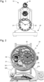
- the invention relates to a sympathetic watch 30, a sympathetic pendulum 20 and a sympathetic timepiece assembly 10 formed by said watch and said pendulum, as visible in the figure 1 .
- the sympathetic pendulum 20 comprises at least one display of a time value, such as a pendulum hour display 21 and a pendulum minute display 22 driven by a pendulum clock movement so as to indicate a current time.
- the sympathetic watch 30 comprises, in a manner similar to the sympathetic pendulum 20, a clock movement to which is connected at least one display of a time value, such as a watch hour display 31 and a watch minute display 32.
- display means any mobile display element known in watchmaking: hand, ring, disc, cursor, flag, etc.
- the watch movement of the watch 30 comprises, in a conventional manner, at least one energy storage barrel 33, for supplying energy to at least one resonator 34, a time-setting mechanism, a display gear train 35 connected to the watch displays and a finishing gear train 36.
- the clockwork movement of the watch 30 advantageously includes a stopping mechanism 37 of the resonator 34, visible in the Figures 2 to 5
- the stop mechanism 37 of the resonator 34 preferably comprises a stop lever 370 arranged to cooperate with an inertial mass, for example constituted by a balance, of the resonator 34, to immobilize it or release it.
- the stop lever 370 is preferably carried by a stop lever rocker 371 subjected to the stress of a spring (not shown in the figures) tending to drive it in rotation so that said stop lever 370 comes to bear against the balance of the resonator 34 to immobilize it.
- the watch movement of the watch 30 preferably comprises a clutch mechanism 38 making it possible to separate the display gear train 35 from the finishing gear train 36, as illustrated in the Figures 6 and 7 .
- the clutch mechanism 38 allows, when disengaged, the rotation of the hour 31 and minute 32 displays independently of the finishing gear 36, and when engaged the driving of the display gear 35, and therefore of said displays, by the finishing gear 36.
- the clutch mechanism 38 comprises two arms 380 and 381 forming a clamp whose function is to provide engagement and disengagement.
- the engagement and disengagement positions are defined by the angular spacing of the arms 380 and 381 relative to each other.
- the clutch mechanism 38 is engaged when the arms 380 and 381 are spaced apart from each other and is disengaged when the arms 380 and 381 are brought closer to each other, as shown in figures 3 And 5 corresponding to the Figures 6 and 7 .
- the two arms 380 and 381 are biased towards the clutch position by a clutch spring 382.
- the clutch spring 382 applies a return force to one of the arms called “first arm” 380 in the remainder of the text, which is configured to transmit this return force to the other arm, called “second arm” 381.
- the clutch mechanism 38 also includes a friction spring 383, visible in the Figures 6 and 7 , assembled on the finishing gear 36 and tending to move a movable serge 384 axially against the display gear 35, such that said finishing gear 36 is engaged by friction of this felloe 384 with a disk 385 secured to said display gear 35.
- the arms 380 and 381 are arranged to oppose the action of the friction spring 383 in order to move said finishing gear 36 away from the display gear 35 when the clutch mechanism 38 is disengaged.
- the clockwork movement of the watch 30 also advantageously comprises a zero-reset mechanism intended to move each hour 31 and minute 32 display of the watch 30 to a predetermined reference position, for example at ten o'clock and ten minutes on the figure 3 , or twelve hours and zero minutes on the figure 11 .
- the reset mechanism comprises a heart cam 390 integral in rotation with the hour display 31, and a hammer 391 arranged to cooperate in support with said heart cam 390 under the action of a hammer spring 392, so as to occupy an active position in which it constrains the rotation of heart cam 390 to its smallest radius.
- the reset mechanism comprises a heart cam secured to the hour display and a heart cam secured to the display of the minute display 32, and comprises two hammers arranged to respectively cooperate in support with each of said heart cams, under the action of dedicated springs.
- the minute display 32 is driven towards the predetermined reference position by the hour display 31 and by a timer gear train 311.
- the hammer 391 can be recalled and maintained in an inactive position, also called the “armed position” in the remainder of the text, by an actuator as described in more detail below, so as to move it away from the came heart 390 when the watch 30 indicates the current time, that is to say when it is in a state called “normal operation”.
- the hammer 391 is held in the armed position when the watch 30 is set to the time as described in more detail below.
- the watch movement of the watch 30 may also include a toothed wheel 394, such as a star, carried by a minute display wheel and intended to cooperate with a jumper 393 to maintain the minute display 32 in position at a regular pace when said watch 30 is set to the time as described in detail below.
- a toothed wheel 394 such as a star
- the sympathetic assembly 10 comprises at least one connecting mechanism between the pendulum 20 and the watch 30, schematically represented in the figures 2 And 9 , intended to mechanically cooperate the pendulum 20 and the watch 30 when the latter is placed in a receptacle of the pendulum 20, in a transfer position.
- this connection mechanism comprises at least two separate transmission lines having different functions from each other and intended to transmit a movement from the clock 20 to the watch 30.
- Each transmission line is constituted by a watch actuator 30 and by a clock actuator 20, said actuators being able to cooperate with each other.
- the watch 30 comprises a first and a second actuator 310 and 320 respectively intended to cooperate with a first and a second actuator 210 and 220 of the clock 20.
- the first and second actuators 210 and 220 of the clock 20 are intended to cooperate respectively with the first and second actuators 310 and 320 of the watch 30 so as to transmit a movement to them, preferably a translational movement.
- the first and second actuators 310 and 320 of the watch 30 are in the form of pushers as shown in the Figures 3 to 5 , 9 And 10 .
- the first and second actuators 310 and 320 of the watch 30 and the first and second actuators 210 and 220 of the clock 20 comprise, at their ends by which they cooperate, coupled magnetic or ferromagnetic elements which make it possible to promote the guidance of the transmission of the translational movement.
- the first actuator 310 of the watch 30 is connected to a transmission lever 39 such that the movement of said first actuator 310 of the watch 30 modifies the angular position of said transmission lever 39. More precisely, the first actuator 310 is connected to the transmission lever 39 by a pivot arranged between a first end of said lever at which it is rotatable and a second end which is free.
- the transmission lever 39 is configured so as to be adapted to cooperate with the hammer 391, with the clutch mechanism 38, with the minute jumper 393 and with the stop lever 370.
- the transmission lever 39 comprises a protrusion, for example formed by a tenon or a pin 395 arranged at its second end.
- the protrusion is designated by a pin for reasons of clarity.
- the pin 395 is able to rest against the stop lever rocker 371 so as to exert a force going against that of the spring applied against said stop lever rocker 371.
- the pin 395 is able to rest against a side of the hammer 391 so as to keep it in the armed position and is able to engage in a notch 396 of said hammer 391 so as to allow it to move into the active position under the action of the hammer spring 392.
- the pin 395 is adapted to bear against one of the arms 381 of the clutch mechanism 38 so as to be able to drive said clutch mechanism 38 into the disengaged position.
- the pin 395 is adapted to bear against one of the sides of the jumper 393 so as to be able, depending on the position of the transmission lever 39, to maintain said jumper 393 in an armed position, in which it is inactive, or to allow its movement into an active position in which it cooperates with the toothed wheel 394, under the action of a jumper spring 3962, by engaging in a notch 3961 of said jumper 396.
- the pin 395 bears against a flank of the second arm 381 and is capable, when the transmission lever 39 is moved, of causing the movement of said second arm 381 against the return force of the clutch spring 382.
- the second arm 381 is configured to drive the first arm 380 in movement against the return force of said clutch spring 382.
- the first and second arms 380 and 381 cooperate with each other at an interface zone by which the first arm 380 forces the second arm 381 to move towards the clutch position under the effect of the return force generated by the clutch spring 382, and by which the second arm 381 is able to transmit a force to the first arm 380 going against the return force, under the effect of the movement of the pin 395, so as to move said first arm 380 and the second arm 381 into the disengaged position.
- the second actuator 320 of the watch 30 can take the form of a corrector rod intended to cooperate with the second actuator 220 of the clock 20.
- the time setting mechanism of the watch 30 may comprise a mobile time setting component, such as a time setting lever 321 formed by a first arm adapted to be biased by the corrector stem to move said time setting lever 321, and by a second arm whose free end is adapted to drive the minute display wheel in rotation, for example by one tooth by back-and-forth movement of the second actuator 320.
- a mobile time setting component such as a time setting lever 321 formed by a first arm adapted to be biased by the corrector stem to move said time setting lever 321, and by a second arm whose free end is adapted to drive the minute display wheel in rotation, for example by one tooth by back-and-forth movement of the second actuator 320.
- the minute display wheel is held in position by the jumper 393, between each movement caused by the activation of the second actuator 320 and after setting the time of the watch 30.
- the clock 20 is intended to set the time of the watch 30, at the request of a user or of the clock 20, by the action of the first and second actuators 210 and 220 on those of said watch 30 as described in the remainder of the text.
- the time setting of the watch 30 makes it possible to adjust, for example, the following indications: hours, minutes, dates, days of the week, months, moon phases. In the present text, a time setting is described making it possible to adjust the display of the hours and minutes of the watch 30 step by step.
- the first actuator 310 of the watch 30 is configured to adopt several successive distinct positions, under the action of the first actuator 210 of the clock 20.
- the solicitation of the first actuator 310 of the watch 30 by the first actuator 210 of the clock 20 allows the performance of time setting operations of the displays of the watch 30 in a sequential manner.
- the watch 30 and the clock 20 do not cooperate with each other so that the watch 30 can be freely removed from the receptacle.
- the first and second actuators 310 and 320 of the watch 30 cooperate respectively with those of the clock 20 so that the actuators of the clock 20 can impart a movement to the actuators of the watch 30.
- successive stresses of the first actuator 210 of the clock 20 cause the sequence of all the operational phases followed by the initial phase, in a cyclical manner.
- Each phase corresponds to a specific position of the first actuator 210 of the clock 20, and consequently, of the first actuator 310 of the watch 30.
- the means of the clock 20 making it possible to act on the first and second actuators 210 and 220 of said clock 20 so that the latter respectively actuate the first and second actuators 310 and 320 of the watch 30.
- the clock movement of the clock 20 may comprise a snail cam 230 on the periphery of which is arranged in support a first end of a feeler 231 when it occupies an active position. Said first end of said feeler 231 is arranged set back from the snail cam 230 when it occupies a rest position in which it is biased by a feeler return spring not shown in the figures.
- the rest position of the feeler 231 corresponds to the reference position of the displays of the watch 30 added by a safety delay corresponding to a duration desired offset for setting the watch time and to ensure a waiting time, for example five minutes, for restarting the watch, as described below.
- the snail cam 230 is kinematically connected to the hour display 21 of the clock 20, so that its angular position characterizes a value of said hour display 21 of the clock 20 and consequently of the current time.
- the snail cam 230 is arranged so as to make one revolution in twelve hours and has one hundred and forty-four bearings on its circumference.
- the feeler 231 is then capable of resting in contact with a new bearing every five minutes.
- the clock movement of the pendulum 20 may include a jumping mechanism connecting the hour display 21 to the snail cam 230, so as to drive the latter in rotation every 5 minutes.
- the feeler 231 is arranged to be mobile in rotation so as to transfer the value of the hour display 21 of the clock 20 to the second actuator 220 of the clock 20.
- the feeler 231 is configured to allow the movement of the second actuator 220 of the clock 20 to be driven over a travel representative of the difference between the reference position of the displays of the watch 30 and the current time indicated by the displays of the clock 20.
- the feeler 231 is connected to a rack 232 at a second end opposite the first end, by means of an elastic connection 238.
- the rack 232 is arranged to cooperate with a transmission gear configured to drive the second actuator 220 according to the time indicated by the minute 22 and hour 21 displays of the clock 20.
- the transmission gear is preferably intended to be driven in rotation by a dedicated energy source, preferably by a barrel. dedicated, called “auxiliary barrel” 234.
- the energy source can alternatively take the form of a weight linked by a cable to a drum, in a manner known as such to those skilled in the art.
- This reference taking of the time indicated by the clock 20 is done in a similar manner, with one difference, to that performed by a minute part of an on-demand minute repeater mechanism.
- the difference lies in the fact that in the present invention, the counting is performed by the travel of the feeler 231 from its rest position to its active position, that is to say when the feeler 231 moves to contact with the snail cam 230; whereas for a minute repeater, the counting is performed by the travel of a minute part from an active position in which it is in contact with a minute snail, to a rest position.
- the transmission gear train comprises a first toothed wheel 235 meshed with the rack 232, and a second toothed wheel 236 arranged to be able to move the second actuator 220 of the pendulum 20, said first and second toothed wheels 235 and 236 being kinematically connected to each other.
- the first and second toothed wheels 235 and 236 are carried by the auxiliary barrel 234 and kinematically connected to the second actuator 220, as shown in figure 9 .
- the clock movement of the pendulum 20 further comprises a clutch lever 240 adapted to disengage the first and second toothed wheels 235 and 236 from each other, and more precisely the first toothed wheel 235 and the auxiliary barrel 234.
- the clutch lever 240 is fixed in a rotatable manner on the frame of the pendulum and is configured so as to be, in a clutch position, engaged with a toothed wheel, called the “third toothed wheel” 237, kinematically linked to the toothed wheel 235 by a satellite gear train, and to be, in a disengaged position, disengaged from said third toothed wheel 237.
- the second toothed wheel 236 is advantageously meshed with an output wheel, here formed by a ratchet 233 arranged to be mobile in rotation and having a plurality of triangular teeth, also called “wolf teeth” by those skilled in the art, against one of which the second actuator 220 of the pendulum 20 is arranged to bear.
- This second actuator 220 of the pendulum 20 takes the form of a control lever in the preferred embodiment of the invention shown in the figures 2 And 9 .
- This control lever is for example urged towards the ratchet 233 by elastic return means or by gravity, so as to be driven by a back and forth movement during the rotation of the wolf teeth of the ratchet 233.
- the second actuator 220 is thus adapted to alternately take two distinct extreme positions during rotation of the ratchet 233.
- the second actuator 220 of the pendulum 20 ensures transmission of an impulse to the second actuator 320 of the watch 30, in order to move it between two extreme positions.
- the rotational speed of the ratchet 233 is advantageously regulated by an escapement speed regulator known as such to those skilled in the art and similar to that shown in the detailed view of the figure 9 for regulating the rotation of the cam of the first actuator.
- the elastic connection 238 is connected to an all-or-nothing device 242 adapted to act on the ratchet 233 and on the clutch lever 240.
- the elastic connection 238 and the all-or-nothing device 242 are configured so that, when the feeler 231 is rotated by the rack 232, under the effect of the auxiliary barrel 234, until it comes into contact with the snail cam 230, the elastic connection 238 deforms and stresses the all-or-nothing device 242 such that the latter immobilizes the ratchet 233 and pivots the lever clutch 240 in order to separate the first toothed wheel 235 and the auxiliary barrel 234.
- the all-or-nothing device 242 comprises a hook 241 adapted to cooperate with the teeth of the ratchet 233 so as to immobilize the latter.
- the clutch lever therefore releases the feeler 231 from the grip of the auxiliary barrel 234, which allows the rake 232 and the feeler 231 to return to their rest positions under the constraint of their return spring (not shown in the figure). figure 9 ).
- the movement of the feeler 231 from its rest position to its active position is triggered by the first actuator 210 of the pendulum 20, by dedicated means not shown in the figures and within the reach of those skilled in the art, when said first actuator 210 occupies a predetermined position as described in more detail in the remainder of the text.
- the feeler 231 upon triggering of the first actuator 210, the feeler 231 is driven in rotation by means of the rack 232 meshing with the auxiliary barrel 234, as well as the ratchet 233 which imparts a back-and-forth movement to the second actuator 220, and this until the feeler 231 rests against the snail cam 230.
- the feeler 231 reaches its active position, the ratchet 233 is immobilized and the rack 232 is detached from the auxiliary barrel 234, so that the feeler 231 is driven to its rest position by the feeler return spring.
- the pendulum 20 may include a cam 211 as shown in the detailed view of the figure 9 to cause the movement of the first actuator 210 of the pendulum 20.
- This cam 211 is different from the ratchet 233 of the second actuator 220 insofar as it has portions of profiles connected by ramps configured to move said first actuator 210 according to at least three distinct positions, one after the other, so as to define a time cycle of predetermined positions which follow one another at a defined speed.
- the first actuator 210 takes the form of a control rod or a control lever as shown in the figures 2 And 9 , and is also biased towards the cam 211 by elastic return means 212, as visible in the figure 9 .
- the first actuator 210 can be moved in translation or in rotation by the cam 211, depending on the embodiment considered.
- cam 211 is intended to pivot counterclockwise, contrary to the general view of the same figure 9 or the cam is intended to pivot clockwise for reasons specific to the construction of the mechanism.
- the cam 211 is driven in rotation by a dedicated energy source, such as a weight or a barrel, and is integral with a multiplication gear and a regulation mechanism composed of an escapement and an oscillator, so as to regulate its rotation speed, known as such to those skilled in the art and shown in the detailed view of the figure 9 .
- a dedicated energy source such as a weight or a barrel
- a regulation mechanism composed of an escapement and an oscillator, so as to regulate its rotation speed, known as such to those skilled in the art and shown in the detailed view of the figure 9 .
- the pendulum 20 comprises two control means 2130 and 2131 intended to authorize or prohibit the pivoting of the first actuator 210 of the pendulum 20.
- the control means 2130 and 2131 are arranged to allow the rotation of the cam 211 and thus the modification of the position of the first actuator 210 of the pendulum 20.
- the two control means 2130 and 2131 allow or prohibit the rotation of the cam 211 on one revolution.
- one of the control means called “first control means” 2130, allows the rotation of the cam 211 to be started and immobilized, that is to say to start the time-setting method described in detail below, and to complete it.
- the other control means called “second control means” 2131 ensures the stopping of the first actuator 210 of the clock 20 during the movement of the second actuator 220 followed by the start of the five-minute waiting time to release the first actuator 310 of the pendulum 20 again.
- each of the first and second control means 2130 and 2131 is formed by a lever intended to rest against the circumference of a control cam 2132 concentric with the cam 211 and integral with the latter.
- the circumference of the control cam 2132 comprises at least one radial notch respectively intended to cooperate with the two control means 2130 and 2131.
- the levers each include a beak designed to cooperate with the teeth of one of the mobiles of the multiplication gear to immobilize said gear.
- the pendulum 20 comprises only a single control means in the form of a lever, said lever then comprising two beaks.
- the control cam 2132 and the cam 211 can form a single single-piece cam.
- the first control means 2130 is arranged to be operated by the user.
- the second control means 2131 is arranged to be controlled by the clock 20 at the next passage of five minutes following the end of the counting carried out by the feeler 231, by a mechanism linked to the rotation of the minute display of the clock 20. This is in order to generate the waiting time to release the first actuator 310 of the clock 20.
- the first control means 2130 When the first control means 2130 is operated or piloted, it allows the rotation of the cam 211, and therefore the solicitation of the first actuator 310 of the watch 30 by the first actuator 210 of the clock 20, and consequently the movement of said first actuator 310 of the watch 30 from an initial position to a first position, i.e. the start of a first operational phase.
- this change of position is carried out over a period of approximately five seconds and the first position is maintained for approximately five seconds.
- a second operational phase is then started in which the first actuator 210 of the clock 20 causes the first actuator 310 of the watch 30 to move into a second position.
- the second control means 2131 cooperates with the notch of the control cam 2132 so as to immobilize the cam 211 for the waiting time necessary to perform the function of the second actuator described above added to the waiting time for the next passage of the clock to the time displayed by the watch, in steps of 5 minutes for example.
- a third phase is started in which the second control means 2131 is released from the notch of the control cam 2132, which makes it possible to restart the rotation of the cam 211 and thus the solicitation of the first actuator 310 of the watch 30 by the first actuator 210 of the clock 20, so that said first actuator 310 of the watch 30 occupies a third position corresponding to the initial position.
- this change of position is carried out over a period of approximately 0.1 second and the third position is maintained by the cooperation of the first control means 2130 with the notch of the control cam 2132 so as to immobilize the cam 211.
- the two control means 2130 and 2131 are configured to alternately authorize or prohibit the actuation of the first actuator 210 of the pendulum 20.
- the first actuator 210 of the pendulum 20 drives the first actuator 310 of the watch 30 into the first position.
- the watch 30 in this first operational phase is shown in the figures 3 And 11 .
- the first actuator 210 of the clock 20 bears against portions of the profile of the cam 211.
- the first actuator 210 of the clock 20 occupies the initial position in which it bears against a sector 217 of a first portion 2170 of the profile of the cam 211.
- This first portion 2170 comprises a first ramp 219 defining an increase in cam radius making it possible to drive, from its initial position, the first actuator 310 of the watch 30 into its first position at a controlled speed, for example 5 seconds, during the first operational phase.
- the first actuator 310 of the watch is driven into its first position when the first actuator 210 of the pendulum 20 reaches, following its travel along the first ramp 219, a second portion 214 of the cam 211.
- the first operational phase is carried out when the first actuator 210 of the clock 20 is supported against the second portion 214.
- This second portion 214 is concentric, that is to say the radius of the cam 211 on the second portion 214 is constant, so as to maintain the first actuator 310 of the watch 30 in the first position for a predefined time, for example 5 seconds.
- This predefined time allows the accomplishment of the following functions, during the first operational phase.
- the first actuator 310 of the watch 30 is configured such that when it occupies the first position, it actuates the reset mechanism so as to move the hour 31 and minute 32 displays of the watch 30 to their reference position.
- the first actuator 310 of the watch 30 drives the transmission lever 39 in rotation until the pin 395 engages in the notch 396 of the hammer 391. This thus allows the movement of the hammer 391 to the active position under the action of the hammer spring 392, and consequently the movement of the hour 31 and minute 32 displays to their reference position.
- the first actuator 310 of the watch 30 is also configured so that when it occupies the first position, it acts on the clutch mechanism 38 so as to cause the disengagement of the finishing gear train 36 and the display gear train 35 and causes the driving of the stop lever 370 into a position blocking the resonator 34 of the watch 30.
- the rotation of the transmission lever 39 caused by the movement of the first actuator 310 of the watch 30 towards its first position drives, by means of the pin 395, the first and second arms 380 and 381 into rotation towards each other, against the return force generated by the clutch spring 382, and thus the disengagement of the clutch mechanism 38.
- the rotation of the transmission lever 39 causes the movement of the stop lever rocker 371 under the effect of the force generated by the spring of stop lever until stop lever 370 rests against the balance wheel, thereby stopping resonator 34.
- the first actuator 210 of the pendulum 20 is driven to bear against a ramp 216 of a third portion 2150 of the profile of the cam 211 until it reaches, within a practically instantaneous time, for example 0.1 second, a sector 215 of said third portion 2150.
- a sector 215 of said third portion 2150 When it reaches this sector 215, the first actuator 210 of the pendulum 20 drives the first actuator 310 of the watch 30 into the second position.
- the ramp 216 is defined by a decrease in the radial section, representing the radius, of the cam 211 considering the direction of rotation of said cam 211 in the present text.
- the first actuator 310 of the watch 30 is therefore further back from the watch 30 than when it occupies the first position.
- Watch 30 in this second operational phase is shown on the figures 4 And 12 .
- the first actuator 310 of the watch 30 is configured so that it rearms the hammer 391, that is to say that it drives the hammer 391 away from the heart cam 390, in its inactive position.
- the pin 395 is forced to withdraw from the notch 396 of the hammer 391 during the movement of the transmission lever 39 caused by the first actuator 310 of the watch 30 when it is driven to its second position.
- the pin 395 therefore subsequently rests against the flank of the hammer 391, and causes it to rotate against the hammer spring 392.
- resetting the hammer 391 does not cause any change in the position of the hour displays 31 and minutes 32 of watch 30 thanks to the cooperation between the jumper 393 and the toothed wheel 394 carried by the minute display wheel.
- the first actuator 210 of the pendulum 20 is configured so that, when it is driven into its second position, it causes the ratchet 233 to rotate and the feeler 231 to move from its rest position to its active position, and consequently the actuation of the second actuator 220 of the pendulum 20.
- the first actuator 210 of the pendulum 20 can for example act by means of a dedicated mechanism not shown in the figures, on the hook 241, so as to move it back from the ratchet 233 in order to allow its rotation under the stress of the auxiliary barrel 234.
- the movement of the hook 241 has the effect of pivoting the clutch lever 240 so as to rotationally secure the first and second toothed wheels 235 and 236 with each other, causing the rack 232 to rotate under the stress of the auxiliary barrel 234 and thus the feeler 231 to pivot from its rest position to its active position.
- the second actuator 220 of the pendulum 20 therefore drives the second actuator 320 of the watch 30 in a back-and-forth movement between two extreme positions.
- the angular travel of the feeler 231 corresponds to the number of steps separating the time corresponding to the reference position of the displays of the watch 30, from the current time indicated by the displays of the clock 20.
- the second actuator 320 of the watch 30 is arranged to drive, during each of its back-and-forth movements, the minute display 32 of the watch 30 by a step of a given value via the time-setting lever 321, the driving of the minute display 32 causing the movement of the hour display 31.
- the step value is an integer submultiple of the hour: one minute, two minutes, three minutes, four minutes, five minutes, six minutes, ten minutes, twelve minutes, fifteen minutes, twenty minutes, thirty minutes.
- the snail cam 230 and the feeler 231 are configured so that the second actuator 220 of the pendulum 20 drives the second actuator 320 of the watch 30 so as to move the minute display 32 so that the position of the minute displays 32 and the hour displays 31 of the watch 30 corresponds to that of the minute displays 22 and the hour displays 21 of the pendulum 20 plus at least one step.
- the second actuator 320 of the watch 30 is activated by the second actuator 220 of the clock 20 so as to drive the hour 31 and minute 32 displays of the watch 30 in successive steps, to a position corresponding to that of the current time increased by a predetermined additional number of steps, for example a number of steps corresponding to a value of five minutes.
- the second control means 2131 is arranged so as to immobilize the cam 211 during the actuation of the second actuator 220 of the clock 20, that is to say during the increased time setting of the watch 30, and during the waiting period, for example five minutes, at the end of said increased time setting of the watch 30.
- the third operational phase is activated, by the second control means 2131 controlled following the immobilization of the second actuator 220 of the clock 20 and by the passage to the next 5 whole minutes of the clock 20 as described above.
- the cam 211 is driven in rotation so that the first actuator 210 of the clock 20 bears against a fourth portion 218 of the profile of the cam 211 in the form of a ramp so as to drive the first actuator 310 of the watch 30 into its third position, that is to say into its initial position.
- the cam 211 is immobilized, in this third phase, by the first control means 2130.
- the fourth portion 218 defines a decrease in the radial section of the cam 211 considering the direction of rotation of said cam 211. In the third position, the first actuator 310 of the watch 30 is therefore further back from the watch 30 than when it occupies the second position.
- Watch 30 in this third operational phase is shown on the figures 5 And 13 .
- the first actuator 310 of the watch 30 is configured to cause the clutch mechanism 38 to engage and the stop lever 370 to be driven into a position for releasing the resonator 34 of the watch 30.
- the first actuator 310 of the watch 30 may be configured to, during this phase, maintain the winding of the hammer 391.
- the rotation of the transmission lever 39 drives, by means of the pin 395, the first and second arms 380 and 381 to rotate each other in opposite directions under the effect of the return force generated by the clutch spring 382.
- the jumper 393 is configured such that, when moving the transmission lever 39 when the first actuator 310 of the watch 30 is driven towards its third position, the pin 395 bears on one of its sides so as to move it away from the toothed wheel 394, which allows the rotation of the minute display 32 of the watch 30 to be released.
- the first actuator 210 of the clock 20 is configured so as to control the first actuator 310 of the watch 30 to begin the implementation of the third operational phase, when the current time, that is to say the time indicated by the hour 21 and minute 22 displays of the clock 20, corresponds to the time indicated by the hour 31 and minute 32 displays of the watch 30.
- the third phase corresponds to the initial phase, that is to say a state of the watch 30 in which it is before the start of the first phase with the exception of the displays of the watch 30, which are in phase with those of the clock 20.
- the transmission lever 39 is subjected to a return force by a lever spring tending to move it into a position called the “initial position” corresponding to that in which it is when the first actuator 310 of the watch 30 is in the third position.
- This return force is advantageously dimensioned so that the transmission lever 39 is driven into the initial position when the first actuator 310 of the watch 30 is not stressed by the first actuator 210 of the clock 20, that is to say when the first actuator 310 of the watch 30 is in the third position.
- the position of the first and second actuators 310 and 320 of the watch 30 in this third phase corresponds to rest positions in which they are arranged, in particular, when the watch 30 does not cooperate with the clock 20.
- durations of the aforementioned operational phases and of the transitions between each of said phases are proportional to the angular amplitude over which the cam profile portions 211 and the ramps between said portions extend.
- the transmission lever 39 can cooperate with each of the two arms 380 and 381, said arms 380 and 381 then being independent of each other and cooperating with a dedicated clutch spring.
- one of the arms 380 or 381 or the arms 380 and 381 may comprise an elastic portion so as to constitute the clutch spring. This characteristic advantageously makes it possible to avoid the use of a dedicated clutch spring.
- transmission lever 39 can be replaced by a column wheel as used in chronograph type watch movements.
Landscapes
- Physics & Mathematics (AREA)
- General Physics & Mathematics (AREA)
- Measurement Of Unknown Time Intervals (AREA)
- Electromechanical Clocks (AREA)
- Electric Clocks (AREA)
Claims (23)
- Sympathische Uhr (30), die dazu bestimmt ist, mit einer sympathischen Pendule (20) zusammenzuwirken, umfassend ein Uhrwerk, mit dem mindestens eine Anzeigeeinheit eines Zeitwerts (31, 32) verbunden ist, einen Kupplungsmechanismus (38), der es ermöglicht, ein Anzeigeräderwerk (35) und eine Finissage (36) voneinander zu trennen, und einen Rückstellmechanismus, der dazu bestimmt ist, mindestens eine Uhranzeigeeinheit in eine vorbestimmte Referenzposition zu bewegen, wobei die Uhr (30) ein erstes und ein zweites Wirkglied (310, 320) umfasst, die jeweils dazu bestimmt sind, mit einem ersten und einem zweiten Wirkglied (210, 220) der Pendule (20) zusammenzuwirken, wobei das erste Wirkglied (310) der Uhr (30) imstande ist, mindestens drei verschiedene aufeinanderfolgende Positionen einzunehmen, um auf den Kupplungsmechanismus (38) und auf den Rückstellmechanismus zu wirken, wobei das zweite Wirkglied (320) der Uhr (30) imstande ist, abwechselnd zwei Endpositionen einzunehmen, um nur dann auf den Zeiteinstellmechanismus zu wirken, wenn das erste Wirkglied (310) eine seiner verschiedenen aufeinanderfolgenden Positionen einnimmt.
- Uhr (30) nach Anspruch 1, wobei das erste Wirkglied (310) konfiguriert ist, um auf einen Stoppmechanismus (37) eines Resonators (34) der Uhr in zwei verschiedenen aufeinanderfolgenden Positionen zu wirken.
- Uhr (30) nach Anspruch 2, wobei das erste Wirkglied (310) der Uhr (30) konfiguriert ist, um über einen Übertragungshebel (39), mit dem er verbunden ist, auf den Kupplungsmechanismus (38), den Stoppmechanismus (37) und den Rückstellmechanismus zu wirken, wobei der Übertragungshebel konfiguriert ist, um gleichzeitig den Kupplungsmechanismus (38) und den Rückstellmechanismus zu beanspruchen.
- Uhr (30) nach Anspruch 3, wobei sich der Übertragungshebel (39) zwischen einem ersten Ende des Hebels, in dessen Bereich er drehbeweglich ist, und einem zweiten Ende erstreckt, das eine Ausstülpung (395) beinhaltet, über die der Übertragungshebel (39) mit dem Rückstellmechanismus, dem Kupplungsmechanismus (38) und dem Stoppmechanismus (37) zusammenwirkt.
- Uhr (30) nach einem der Ansprüche 3 oder 4, wobei der Übertragungshebel (39) einer Rückstellkraft durch eine Hebelfeder unterliegt, die dazu tendiert, ihn in eine Ausgangsposition zu bewegen, in der er den Rückstellmechanismus in eine inaktive Position, den Kupplungsmechanismus (38) in eine Kupplungsposition und den Stoppmechanismus (37) in eine Position treibt, in der er den Resonator (34) freigibt.
- Uhr (30) nach einem der Ansprüche 1 bis 5, wobei der Kupplungsmechanismus (38) zwei Arme (380, 381), die eine Zange bilden, und eine Reibungsfeder (383) beinhaltet, die dazu tendiert, die Finissage (36) in Eingriff mit dem Anzeigeräderwerk (35) zu bewegen, wobei die Arme (380, 381) durch eine Kupplungsfeder (382) in eine Kupplungsposition beansprucht werden und konfiguriert sind, sodass, wenn das erste Wirkglied (310) eine seiner Positionen einnimmt, die als "erste Position" bezeichnet wird, gegen die Kupplungsfeder (382) in eine Auskuppelposition getrieben werden, in der sie der Wirkung der Kupplungsfeder (382) und der Reibungsfeder (383) entgegenwirken, um die Finissage (36) von dem Anzeigeräderwerk (35) zu entfernen.
- Uhr (30) nach einem der Ansprüche 3 bis 5 und Anspruch 6, wobei die Arme (380, 381) an einem Schnittstellenbereich miteinander zusammenwirken, durch den einer der Arme, der sogenannte "erste Arm" (380), imstande ist, den anderen Arm, den sogenannten "zweiten Arm" (381), zu zwingen, sich unter der Wirkung der von der Kupplungsfeder (382) erzeugten Rückstellkraft in die Kupplungsposition zu bewegen, und durch die der zweite Arm (381) imstande ist, eine Kraft auf den ersten Arm (380) zu übertragen, der er durch den Übertragungshebel (39) unterliegt, wenn das erste Wirkglied (310) seine erste Position einnimmt, wobei diese Kraft die Arme (380, 381) in die Auskuppelposition bewegt.
- Uhr (30) nach einem der Ansprüche 3 bis 5 oder 7, wobei der Rückstellmechanismus mindestens eine Herz-Kurvenscheibe (390), die drehfest mit der Anzeigeeinheit eines Zeitwerts (31, 32) verbunden ist, und mindestens einen Hammer (391) beinhaltet, der angeordnet ist, um unter der Wirkung einer Hammerfeder (392) in Anlage mit der mindestens einen Herz-Kurvenscheibe (390) zusammenzuwirken, um eine aktive Position einzunehmen und die Herz-Kurvenscheibe (390) in Drehung zu zwingen, bis er an ihrem kleinsten Radius anliegt, wenn das erste Wirkglied (310) eine seiner Positionen, die als "erste Position" bezeichnet wird, einnimmt, wobei der Hammer (391) konfiguriert ist, um vom Übertragungshebel (39) rückgestellt, und in einer inaktiven Position gehalten zu werden, in der er von der Herz-Kurvenscheibe (390) entfernt wird, wenn das erste Wirkglied (310) eine andere Position einnimmt.
- Uhr (30) nach den Ansprüchen 4 und 8, wobei der Übertragungshebel (39) konfiguriert ist, sodass die Ausstülpung (395) in eine Kerbe (396) des Hammers (391) eingreift, damit letzterer unter der Wirkung der Hammerfeder (392) in die aktive Position getrieben wird, sodass die Ausstülpung (395) aus der Kerbe (396) herausgezogen wird und an einer Flanke des Hammers (391) anliegend ruht, um diesen letzteren in die inaktive Position zu treiben und in dieser zu halten.
- Uhr (30) nach einem der Ansprüche 3 bis 5 oder 7 bis 9, wobei der Stoppmechanismus (37) einen Stopphebel (370) beinhaltet, welcher der Beanspruchung einer Feder unterliegt, die dazu tendiert, diesen letzteren in Drehung zu versetzen, sodass der Stopphebel (370) in Anlage gegen eine Unruh des Resonators (34) angeordnet ist, wobei der Übertragungshebel (39) konfiguriert ist, sodass die Ausstülpung (395) eine Kraft ausübt, die sich gegen jene der Feder richtet, die an den Stopphebel (371) angelegt ist.
- Uhr (30) nach einem der Ansprüche 1 bis 10, wobei das Uhrwerk der Uhr (30) ein Zahnrad (394) beinhaltet, das von einem Anzeigedrehteil der Minuten getragen wird, und mit einer Rolle (393) zur Beibehaltung in Position einer Minuten-Anzeigeeinheit (32) in einer regelmäßigen Schrittweite zusammenwirkt.
- Uhr (30) nach einem der Ansprüche 1 bis 11, wobei der Zeiteinstellmechanismus eine bewegliche Zeiteinstellkomponente (321) beinhalten kann, die angepasst ist, um durch einen Impuls des zweiten Wirkglieds (320) der Uhr (30) beansprucht zu werden, um ein Anzeigedrehteil der Minuten um einen Schritt je Impuls des zweiten Wirkglieds (320) der Uhr (30) und in einer einzigen Drehrichtung zu treiben.
- Sympathische Pendule (20), die dazu bestimmt ist, mit einer sympathischen Uhr (30) nach einem der Ansprüche 1 bis 12 zusammenzuwirken, mindestens eine Anzeigeeinheit eines Zeitwerts (21, 22) einer Pendule beinhaltend, das von einem Uhrwerk der Pendule angetrieben wird, dadurch gekennzeichnet, dass sie ein erstes und ein zweites Wirkglied (210, 220) beinhaltet, die dazu bestimmt sind, jeweils mit dem ersten und dem zweiten Wirkglied (310, 320) der Uhr (30) zusammenzuwirken, wobei das erste Wirkglied (210) der Pendule (20) konfiguriert ist, um das erste Wirkglied (310) der Uhr (30) in seine mindestens drei verschiedenen aufeinanderfolgenden Positionen zu bewegen, und das zweite Wirkglied (220) der Pendule (20) konfiguriert ist, um das zweite Wirkglied (320) der Uhr (30) durch eine Hin- und Her-Bewegung zwischen seinen beiden Positionen zu bewegen, wenn das erste Wirkglied der Uhr eine seiner Positionen einnimmt, wobei das Uhrwerk der Pendule (20) mindestens ein Steuermittel (213) beinhaltet, das konfiguriert ist, um die Bewegung des ersten Wirkglieds (210) der Uhr (20) zu steuern oder zu unterbinden.
- Pendule (20) nach Anspruch 13, wobei das Uhrwerk der Pendule (20) eine Staffelkurvenscheibe (230) umfasst, die kinematisch mit der/den Anzeigeeinheit(en) eines Zeitwerts (21, 22) der Pendule (20) verbunden ist, sodass ihre Winkelposition einen Wert der Anzeigeeinheit(en) eines Zeitwerts (21, 22) kennzeichnet, und an dessen Umfang ein erstes Ende eines Tasters (231) in Anlage angeordnet ist, wenn er eine aktive Position einnimmt, wobei das erste Ende von der Staffelkurvenscheibe (230) zurückversetzt ist, wenn der Taster (231) eine Ruheposition einnimmt, wobei das Uhrwerk konfiguriert ist, um das zweite Wirkglied (220) der Pendule (20) auf dem Weg des Tasters (231) zwischen seiner Ruheposition und seiner aktiven Position gemäß einer Anzahl von Hin- und Her-Bewegungen zu bewegen, die für die Differenz zwischen der Referenzposition des oder der Anzeigeeinheiten eines Zeitwerts (31, 32) der Uhr (30) und dem Zeitwert, der von dem oder den Anzeigeeinheiten eines Zeitwerts (21, 22) der Pendule (20) angezeigt wird, repräsentativ ist.
- Pendule (20) nach Anspruch 14, wobei der Taster (231) an einem zweiten, dem ersten Ende gegenüberliegenden Ende einen Rechen (232) beinhaltet, der angeordnet ist, um mit einem ersten Zahnrad (235) eines Übertragungsräderwerks zusammenzuwirken, wobei das Übertragungsräderwerk ein zweites Zahnrad (236) umfasst, das mit dem zweiten Wirkglied (220) der Pendule (20) verbunden ist, um es bei der Bewegung des Tasters (231) von seiner Ruheposition in seine aktive Position hin- und herzubewegen.
- Pendule (20) nach Anspruch 15, wobei das zweite Zahnrad (236) mit einem Sperrrad (233) in Eingriff kommt, das von einer dedizierten Energiequelle in Drehung versetzt wird, und eine Vielzahl von dreieckigen Zähnen beinhaltet, an denen ein zweites Wirkglied (220) der Pendule (20) dazu bestimmt ist angelegt zu werden, um durch eine Hin- und Her-Bewegung bei der Drehung des Sperrrades (233) animiert zu werden.
- Pendule (20) nach Anspruch 15, wobei das zweite Zahnrad (236) mit dem zweiten Wirkglied (220) der Pendule (20) über einen Pleuel-Kurbel-Mechanismus verbunden ist, dessen Pleuelstange dazu bestimmt ist, fest mit dem zweiten Wirkglied (220) der Pendule (20) verbunden zu werden, und dessen Kurbel drehfest mit dem zweiten Zahnrad (236) verbunden ist.
- Pendule (20) nach einem der Ansprüche 15 bis 17, wobei das Uhrwerk der Pendule (20) einen Kupplungshebel (240) beinhaltet, der angepasst ist, um eine Auskuppelposition einzunehmen, in der er das erste Zahnrad (235) trennt, und ein Hilfsfederhaus (234) beinhaltet, das dazu bestimmt ist, das erste Zahnrad (235) und das zweite Zahnrad (236) in Drehung zu versetzen, wobei das Uhrwerk der Pendule (20) weiter eine AON-Vorrichtung (242) umfasst, die konfiguriert ist, um mit dem Kupplungshebel (240) zusammenzuwirken, um ihn in die Auskuppelposition zu treiben, wenn der Taster (231) seine aktive Position erreicht, sodass der Taster (231) unter der Wirkung einer Taster-Rückstellfeder in seine Ruheposition getrieben wird.
- Pendule (20) nach einem der Ansprüche 13 bis 17, wobei das Uhrwerk der Pendule (20) eine Kurvenscheibe (211) umfasst, die durch eine dedizierte Energiequelle in Drehung versetzt wird und ein Kurvenscheibenprofil beinhaltet, an dem anliegend das erste Wirkglied (210) der Pendule (20) angeordnet ist, wobei das Kurvenscheibenprofil aufeinanderfolgende Abschnitte beinhaltet, die angepasst sind, um das erste Wirkglied (210) in mindestens drei verschiedene Positionen zu bewegen, um einen zeitlichen Zyklus von vorbestimmten Positionen zu definieren.
- Pendule (20) nach Anspruch 19, wobei das mindestens eine Steuermittel (213) konfiguriert ist, um die Drehung der Kurvenscheibe (211) zu blockieren oder freizugeben.
- Sympathische Uhrmachereieinheit (10), die eine sympathische Uhr (30) nach einem der Ansprüche 1 bis 12 und eine sympathische Pendule (20) nach einem der Ansprüche 13 bis 20 umfasst.
- Verfahren zur Zeiteinstellung einer Uhr einer sympathischen Uhrmachereieinheit (10) nach Anspruch 21, das nacheinander umfasst:- eine erste Betriebsphase, in der das erste Wirkglied (210) der Pendule (20) das erste Wirkglied (310) der Uhr (30) in eine erste Position treibt, in der letzteres den Rückstellmechanismus beansprucht, der mindestens einen Hammer (391) beinhaltet, um mindestens eine Anzeigeeinheit eines Zeitwerts (31, 32) der Uhr (30) in ihre Referenzposition zu bewegen, er auf den Kupplungsmechanismus (38) einwirkt, um das Auskuppeln der Finissage (36) und des Anzeige-Räderwerks (35) hervorzurufen,- eine zweite Betriebsphase, in der das erste Wirkglied (210) der Pendule (20) einerseits das erste Wirkglied (310) der Uhr (30) in eine zweite Position treibt, in der er den Hammer (391) in eine inaktive Position treibt, und andererseits die Betätigung des zweiten Aktuators (220) der Pendule (20) bewirkt, dass dieser das zweite Wirkglied (320) der Uhr (30) in einer Hin- und Her-Bewegung zwischen seinen beiden Endpositionen antreibt,- eine dritte Betriebsphase, in der das erste Wirkglied (210) der Pendule (20) einerseits das erste Wirkglied (310) der Uhr (30) in eine dritte Position treibt, in der er das Kuppeln des Kupplungsmechanismus (38) bewirkt, wobei das erste Wirkglied (210) der Pendule (20) das erste Wirkglied (310) der Uhr (30) ansteuert, um die Umsetzung der dritten Betriebsphase zu beginnen, wenn der von der oder den Anzeigeeinheiten eines Zeitwerts (31, 32) der Pendule (20) angezeigte Zeitwert dem von der oder den Anzeigeeinheiten eines Zeitwerts (31, 32) der Uhr (30) angezeigten Zeitwert entspricht.
- Verfahren nach Anspruch 22, wobei in der ersten Betriebsphase das erste Wirkglied (310) der Uhr (30) den Stoppmechanismus (37) beansprucht, um den Resonator (34) zu immobilisieren, in der zweiten Betriebsphase das erste Wirkglied (310) der Uhr (30) den Stoppmechanismus (37) in Position hält, und in der dritten Betriebsphase das erste Wirkglied (310) der Uhr (30) den Stoppmechanismus (37) beansprucht, um den Resonator (34) freizugeben.
Priority Applications (4)
| Application Number | Priority Date | Filing Date | Title |
|---|---|---|---|
| EP21217368.6A EP4202575B1 (de) | 2021-12-23 | 2021-12-23 | Sympathique uhr und pendel, die eine sympathique uhreneinheit bilden, und verfahren zum einstellen der uhr der genannten sympathique uhreneinheit |
| US17/965,310 US12468263B2 (en) | 2021-12-23 | 2022-10-13 | Sympatique watch and clock forming a sympatique horological assembly and method for setting the time of the watch of said sympatique horological assembly |
| JP2022169740A JP7446382B2 (ja) | 2021-12-23 | 2022-10-24 | サンパティーク測時器組立体を形成するサンパティーク腕時計及び置時計、並びに前記サンパティーク測時器組立体の腕時計の時間を設定する方法 |
| CN202211662719.2A CN116339100A (zh) | 2021-12-23 | 2022-12-23 | 形成交感钟表组件的交感表和时钟以及用于设置所述交感钟表组件的表的时间的方法 |
Applications Claiming Priority (1)
| Application Number | Priority Date | Filing Date | Title |
|---|---|---|---|
| EP21217368.6A EP4202575B1 (de) | 2021-12-23 | 2021-12-23 | Sympathique uhr und pendel, die eine sympathique uhreneinheit bilden, und verfahren zum einstellen der uhr der genannten sympathique uhreneinheit |
Publications (2)
| Publication Number | Publication Date |
|---|---|
| EP4202575A1 EP4202575A1 (de) | 2023-06-28 |
| EP4202575B1 true EP4202575B1 (de) | 2024-08-14 |
Family
ID=79021849
Family Applications (1)
| Application Number | Title | Priority Date | Filing Date |
|---|---|---|---|
| EP21217368.6A Active EP4202575B1 (de) | 2021-12-23 | 2021-12-23 | Sympathique uhr und pendel, die eine sympathique uhreneinheit bilden, und verfahren zum einstellen der uhr der genannten sympathique uhreneinheit |
Country Status (4)
| Country | Link |
|---|---|
| US (1) | US12468263B2 (de) |
| EP (1) | EP4202575B1 (de) |
| JP (1) | JP7446382B2 (de) |
| CN (1) | CN116339100A (de) |
Family Cites Families (2)
| Publication number | Priority date | Publication date | Assignee | Title |
|---|---|---|---|---|
| JPS49130771A (de) * | 1973-04-16 | 1974-12-14 | ||
| JP3568907B2 (ja) * | 2001-03-14 | 2004-09-22 | セイコーインスツルメンツ株式会社 | 停止レバーを備えたクロノグラフ時計 |
-
2021
- 2021-12-23 EP EP21217368.6A patent/EP4202575B1/de active Active
-
2022
- 2022-10-13 US US17/965,310 patent/US12468263B2/en active Active
- 2022-10-24 JP JP2022169740A patent/JP7446382B2/ja active Active
- 2022-12-23 CN CN202211662719.2A patent/CN116339100A/zh active Pending
Also Published As
| Publication number | Publication date |
|---|---|
| JP7446382B2 (ja) | 2024-03-08 |
| EP4202575A1 (de) | 2023-06-28 |
| JP2023094538A (ja) | 2023-07-05 |
| CN116339100A (zh) | 2023-06-27 |
| US12468263B2 (en) | 2025-11-11 |
| US20230205140A1 (en) | 2023-06-29 |
Similar Documents
| Publication | Publication Date | Title |
|---|---|---|
| EP3945374B1 (de) | Ansprechendes uhrenset | |
| EP4202575B1 (de) | Sympathique uhr und pendel, die eine sympathique uhreneinheit bilden, und verfahren zum einstellen der uhr der genannten sympathique uhreneinheit | |
| CH719311A2 (fr) | Montre et pendule sympathiques formant un ensemble sympathique d'horlogerie et procédé de mise à l'heure de la montre dudit ensemble sympathique d'horlogerie. | |
| EP4189489B1 (de) | Zeitstellungverfahren einer uhr von einer uhreinheit "sympathique" | |
| EP4189493B1 (de) | Uhreinheit "sympathique" | |
| EP4189494B1 (de) | "sympathique" uhrenset | |
| EP4189495B1 (de) | "sympathique" uhrenset | |
| CH717653A2 (fr) | Ensemble sympathique d'horlogerie. | |
| WO2022022827A1 (fr) | Ensemble sympathique d'horlogerie | |
| EP4189491B1 (de) | Zeitstellungverfahren einer uhr in einer uhreinheit "sympathique" | |
| EP4189490B1 (de) | "sympathique" uhrenset | |
| CH717702A1 (fr) | Ensemble sympathique d'horlogerie. | |
| CH717697A2 (fr) | Ensemble sympathique d'horlogerie. | |
| CH717652A2 (fr) | Ensemble sympathique d'horlogerie. | |
| CH717699A1 (fr) | Ensemble sympathique d'horlogerie. | |
| CH717695A2 (fr) | Ensemble sympathique d'horlogerie. | |
| CH717650A2 (fr) | Procédé de mise à l'heure pas-à-pas d'une montre sympathique. | |
| CH717701A1 (fr) | Ensemble sympathique d'horlogerie. | |
| CH717655A2 (fr) | Procédé de mise à l'heure permanente d'une montre sympathique. | |
| CH717696A2 (fr) | Ensemble sympathique d'horlogerie. | |
| CH717700A1 (fr) | Ensemble sympathique d'horlogerie. | |
| CH717703A1 (fr) | Ensemble sympathique d'horlogerie. | |
| CH717651A2 (fr) | Procédé de remontage d'une montre sympathique. | |
| CH717654A2 (fr) | Procédé de mise à l'heure d'une montre sympathique. | |
| WO2022022824A1 (fr) | Remontage d'une montre d'un ensemble sympathique d'horlogerie |
Legal Events
| Date | Code | Title | Description |
|---|---|---|---|
| PUAI | Public reference made under article 153(3) epc to a published international application that has entered the european phase |
Free format text: ORIGINAL CODE: 0009012 |
|
| STAA | Information on the status of an ep patent application or granted ep patent |
Free format text: STATUS: THE APPLICATION HAS BEEN PUBLISHED |
|
| AK | Designated contracting states |
Kind code of ref document: A1 Designated state(s): AL AT BE BG CH CY CZ DE DK EE ES FI FR GB GR HR HU IE IS IT LI LT LU LV MC MK MT NL NO PL PT RO RS SE SI SK SM TR |
|
| P01 | Opt-out of the competence of the unified patent court (upc) registered |
Effective date: 20231109 |
|
| STAA | Information on the status of an ep patent application or granted ep patent |
Free format text: STATUS: REQUEST FOR EXAMINATION WAS MADE |
|
| 17P | Request for examination filed |
Effective date: 20240102 |
|
| RBV | Designated contracting states (corrected) |
Designated state(s): AL AT BE BG CH CY CZ DE DK EE ES FI FR GB GR HR HU IE IS IT LI LT LU LV MC MK MT NL NO PL PT RO RS SE SI SK SM TR |
|
| GRAP | Despatch of communication of intention to grant a patent |
Free format text: ORIGINAL CODE: EPIDOSNIGR1 |
|
| STAA | Information on the status of an ep patent application or granted ep patent |
Free format text: STATUS: GRANT OF PATENT IS INTENDED |
|
| INTG | Intention to grant announced |
Effective date: 20240607 |
|
| GRAS | Grant fee paid |
Free format text: ORIGINAL CODE: EPIDOSNIGR3 |
|
| GRAA | (expected) grant |
Free format text: ORIGINAL CODE: 0009210 |
|
| STAA | Information on the status of an ep patent application or granted ep patent |
Free format text: STATUS: THE PATENT HAS BEEN GRANTED |
|
| AK | Designated contracting states |
Kind code of ref document: B1 Designated state(s): AL AT BE BG CH CY CZ DE DK EE ES FI FR GB GR HR HU IE IS IT LI LT LU LV MC MK MT NL NO PL PT RO RS SE SI SK SM TR |
|
| REG | Reference to a national code |
Ref country code: GB Ref legal event code: FG4D Free format text: NOT ENGLISH |
|
| REG | Reference to a national code |
Ref country code: CH Ref legal event code: EP |
|
| REG | Reference to a national code |
Ref country code: DE Ref legal event code: R096 Ref document number: 602021017162 Country of ref document: DE |
|
| REG | Reference to a national code |
Ref country code: IE Ref legal event code: FG4D Free format text: LANGUAGE OF EP DOCUMENT: FRENCH |
|
| REG | Reference to a national code |
Ref country code: LT Ref legal event code: MG9D |
|
| REG | Reference to a national code |
Ref country code: NL Ref legal event code: MP Effective date: 20240814 |
|
| PG25 | Lapsed in a contracting state [announced via postgrant information from national office to epo] |
Ref country code: NO Free format text: LAPSE BECAUSE OF FAILURE TO SUBMIT A TRANSLATION OF THE DESCRIPTION OR TO PAY THE FEE WITHIN THE PRESCRIBED TIME-LIMIT Effective date: 20241114 |
|
| REG | Reference to a national code |
Ref country code: AT Ref legal event code: MK05 Ref document number: 1713867 Country of ref document: AT Kind code of ref document: T Effective date: 20240814 |
|
| PG25 | Lapsed in a contracting state [announced via postgrant information from national office to epo] |
Ref country code: NL Free format text: LAPSE BECAUSE OF FAILURE TO SUBMIT A TRANSLATION OF THE DESCRIPTION OR TO PAY THE FEE WITHIN THE PRESCRIBED TIME-LIMIT Effective date: 20240814 Ref country code: PL Free format text: LAPSE BECAUSE OF FAILURE TO SUBMIT A TRANSLATION OF THE DESCRIPTION OR TO PAY THE FEE WITHIN THE PRESCRIBED TIME-LIMIT Effective date: 20240814 Ref country code: GR Free format text: LAPSE BECAUSE OF FAILURE TO SUBMIT A TRANSLATION OF THE DESCRIPTION OR TO PAY THE FEE WITHIN THE PRESCRIBED TIME-LIMIT Effective date: 20241115 Ref country code: PT Free format text: LAPSE BECAUSE OF FAILURE TO SUBMIT A TRANSLATION OF THE DESCRIPTION OR TO PAY THE FEE WITHIN THE PRESCRIBED TIME-LIMIT Effective date: 20241216 Ref country code: FI Free format text: LAPSE BECAUSE OF FAILURE TO SUBMIT A TRANSLATION OF THE DESCRIPTION OR TO PAY THE FEE WITHIN THE PRESCRIBED TIME-LIMIT Effective date: 20240814 |
|
| PG25 | Lapsed in a contracting state [announced via postgrant information from national office to epo] |
Ref country code: BG Free format text: LAPSE BECAUSE OF FAILURE TO SUBMIT A TRANSLATION OF THE DESCRIPTION OR TO PAY THE FEE WITHIN THE PRESCRIBED TIME-LIMIT Effective date: 20240814 |
|
| PG25 | Lapsed in a contracting state [announced via postgrant information from national office to epo] |
Ref country code: LV Free format text: LAPSE BECAUSE OF FAILURE TO SUBMIT A TRANSLATION OF THE DESCRIPTION OR TO PAY THE FEE WITHIN THE PRESCRIBED TIME-LIMIT Effective date: 20240814 |
|
| PG25 | Lapsed in a contracting state [announced via postgrant information from national office to epo] |
Ref country code: AT Free format text: LAPSE BECAUSE OF FAILURE TO SUBMIT A TRANSLATION OF THE DESCRIPTION OR TO PAY THE FEE WITHIN THE PRESCRIBED TIME-LIMIT Effective date: 20240814 Ref country code: IS Free format text: LAPSE BECAUSE OF FAILURE TO SUBMIT A TRANSLATION OF THE DESCRIPTION OR TO PAY THE FEE WITHIN THE PRESCRIBED TIME-LIMIT Effective date: 20241214 |
|
| PG25 | Lapsed in a contracting state [announced via postgrant information from national office to epo] |
Ref country code: HR Free format text: LAPSE BECAUSE OF FAILURE TO SUBMIT A TRANSLATION OF THE DESCRIPTION OR TO PAY THE FEE WITHIN THE PRESCRIBED TIME-LIMIT Effective date: 20240814 |
|
| PG25 | Lapsed in a contracting state [announced via postgrant information from national office to epo] |
Ref country code: RS Free format text: LAPSE BECAUSE OF FAILURE TO SUBMIT A TRANSLATION OF THE DESCRIPTION OR TO PAY THE FEE WITHIN THE PRESCRIBED TIME-LIMIT Effective date: 20241114 Ref country code: ES Free format text: LAPSE BECAUSE OF FAILURE TO SUBMIT A TRANSLATION OF THE DESCRIPTION OR TO PAY THE FEE WITHIN THE PRESCRIBED TIME-LIMIT Effective date: 20240814 |
|
| PG25 | Lapsed in a contracting state [announced via postgrant information from national office to epo] |
Ref country code: RS Free format text: LAPSE BECAUSE OF FAILURE TO SUBMIT A TRANSLATION OF THE DESCRIPTION OR TO PAY THE FEE WITHIN THE PRESCRIBED TIME-LIMIT Effective date: 20241114 Ref country code: PT Free format text: LAPSE BECAUSE OF FAILURE TO SUBMIT A TRANSLATION OF THE DESCRIPTION OR TO PAY THE FEE WITHIN THE PRESCRIBED TIME-LIMIT Effective date: 20241216 Ref country code: PL Free format text: LAPSE BECAUSE OF FAILURE TO SUBMIT A TRANSLATION OF THE DESCRIPTION OR TO PAY THE FEE WITHIN THE PRESCRIBED TIME-LIMIT Effective date: 20240814 Ref country code: NO Free format text: LAPSE BECAUSE OF FAILURE TO SUBMIT A TRANSLATION OF THE DESCRIPTION OR TO PAY THE FEE WITHIN THE PRESCRIBED TIME-LIMIT Effective date: 20241114 Ref country code: NL Free format text: LAPSE BECAUSE OF FAILURE TO SUBMIT A TRANSLATION OF THE DESCRIPTION OR TO PAY THE FEE WITHIN THE PRESCRIBED TIME-LIMIT Effective date: 20240814 Ref country code: LV Free format text: LAPSE BECAUSE OF FAILURE TO SUBMIT A TRANSLATION OF THE DESCRIPTION OR TO PAY THE FEE WITHIN THE PRESCRIBED TIME-LIMIT Effective date: 20240814 Ref country code: IS Free format text: LAPSE BECAUSE OF FAILURE TO SUBMIT A TRANSLATION OF THE DESCRIPTION OR TO PAY THE FEE WITHIN THE PRESCRIBED TIME-LIMIT Effective date: 20241214 Ref country code: HR Free format text: LAPSE BECAUSE OF FAILURE TO SUBMIT A TRANSLATION OF THE DESCRIPTION OR TO PAY THE FEE WITHIN THE PRESCRIBED TIME-LIMIT Effective date: 20240814 Ref country code: GR Free format text: LAPSE BECAUSE OF FAILURE TO SUBMIT A TRANSLATION OF THE DESCRIPTION OR TO PAY THE FEE WITHIN THE PRESCRIBED TIME-LIMIT Effective date: 20241115 Ref country code: FI Free format text: LAPSE BECAUSE OF FAILURE TO SUBMIT A TRANSLATION OF THE DESCRIPTION OR TO PAY THE FEE WITHIN THE PRESCRIBED TIME-LIMIT Effective date: 20240814 Ref country code: ES Free format text: LAPSE BECAUSE OF FAILURE TO SUBMIT A TRANSLATION OF THE DESCRIPTION OR TO PAY THE FEE WITHIN THE PRESCRIBED TIME-LIMIT Effective date: 20240814 Ref country code: BG Free format text: LAPSE BECAUSE OF FAILURE TO SUBMIT A TRANSLATION OF THE DESCRIPTION OR TO PAY THE FEE WITHIN THE PRESCRIBED TIME-LIMIT Effective date: 20240814 Ref country code: AT Free format text: LAPSE BECAUSE OF FAILURE TO SUBMIT A TRANSLATION OF THE DESCRIPTION OR TO PAY THE FEE WITHIN THE PRESCRIBED TIME-LIMIT Effective date: 20240814 |
|
| PG25 | Lapsed in a contracting state [announced via postgrant information from national office to epo] |
Ref country code: SM Free format text: LAPSE BECAUSE OF FAILURE TO SUBMIT A TRANSLATION OF THE DESCRIPTION OR TO PAY THE FEE WITHIN THE PRESCRIBED TIME-LIMIT Effective date: 20240814 Ref country code: DK Free format text: LAPSE BECAUSE OF FAILURE TO SUBMIT A TRANSLATION OF THE DESCRIPTION OR TO PAY THE FEE WITHIN THE PRESCRIBED TIME-LIMIT Effective date: 20240814 Ref country code: RO Free format text: LAPSE BECAUSE OF FAILURE TO SUBMIT A TRANSLATION OF THE DESCRIPTION OR TO PAY THE FEE WITHIN THE PRESCRIBED TIME-LIMIT Effective date: 20240814 |
|
| PG25 | Lapsed in a contracting state [announced via postgrant information from national office to epo] |
Ref country code: EE Free format text: LAPSE BECAUSE OF FAILURE TO SUBMIT A TRANSLATION OF THE DESCRIPTION OR TO PAY THE FEE WITHIN THE PRESCRIBED TIME-LIMIT Effective date: 20240814 |
|
| PG25 | Lapsed in a contracting state [announced via postgrant information from national office to epo] |
Ref country code: CZ Free format text: LAPSE BECAUSE OF FAILURE TO SUBMIT A TRANSLATION OF THE DESCRIPTION OR TO PAY THE FEE WITHIN THE PRESCRIBED TIME-LIMIT Effective date: 20240814 |
|
| PG25 | Lapsed in a contracting state [announced via postgrant information from national office to epo] |
Ref country code: IT Free format text: LAPSE BECAUSE OF FAILURE TO SUBMIT A TRANSLATION OF THE DESCRIPTION OR TO PAY THE FEE WITHIN THE PRESCRIBED TIME-LIMIT Effective date: 20240814 Ref country code: SK Free format text: LAPSE BECAUSE OF FAILURE TO SUBMIT A TRANSLATION OF THE DESCRIPTION OR TO PAY THE FEE WITHIN THE PRESCRIBED TIME-LIMIT Effective date: 20240814 |
|
| REG | Reference to a national code |
Ref country code: DE Ref legal event code: R097 Ref document number: 602021017162 Country of ref document: DE |
|
| PLBE | No opposition filed within time limit |
Free format text: ORIGINAL CODE: 0009261 |
|
| STAA | Information on the status of an ep patent application or granted ep patent |
Free format text: STATUS: NO OPPOSITION FILED WITHIN TIME LIMIT |
|
| PG25 | Lapsed in a contracting state [announced via postgrant information from national office to epo] |
Ref country code: MC Free format text: LAPSE BECAUSE OF FAILURE TO SUBMIT A TRANSLATION OF THE DESCRIPTION OR TO PAY THE FEE WITHIN THE PRESCRIBED TIME-LIMIT Effective date: 20240814 |
|
| 26N | No opposition filed |
Effective date: 20250515 |
|
| PG25 | Lapsed in a contracting state [announced via postgrant information from national office to epo] |
Ref country code: LU Free format text: LAPSE BECAUSE OF NON-PAYMENT OF DUE FEES Effective date: 20241223 |
|
| PG25 | Lapsed in a contracting state [announced via postgrant information from national office to epo] |
Ref country code: SE Free format text: LAPSE BECAUSE OF FAILURE TO SUBMIT A TRANSLATION OF THE DESCRIPTION OR TO PAY THE FEE WITHIN THE PRESCRIBED TIME-LIMIT Effective date: 20240814 |
|
| REG | Reference to a national code |
Ref country code: BE Ref legal event code: MM Effective date: 20241231 |
|
| PG25 | Lapsed in a contracting state [announced via postgrant information from national office to epo] |
Ref country code: BE Free format text: LAPSE BECAUSE OF NON-PAYMENT OF DUE FEES Effective date: 20241231 |
|
| PG25 | Lapsed in a contracting state [announced via postgrant information from national office to epo] |
Ref country code: IE Free format text: LAPSE BECAUSE OF NON-PAYMENT OF DUE FEES Effective date: 20241223 |
|
| REG | Reference to a national code |
Ref country code: CH Ref legal event code: U11 Free format text: ST27 STATUS EVENT CODE: U-0-0-U10-U11 (AS PROVIDED BY THE NATIONAL OFFICE) Effective date: 20260101 |
|
| PGFP | Annual fee paid to national office [announced via postgrant information from national office to epo] |
Ref country code: DE Payment date: 20251126 Year of fee payment: 5 |
|
| PGFP | Annual fee paid to national office [announced via postgrant information from national office to epo] |
Ref country code: GB Payment date: 20251120 Year of fee payment: 5 |
|
| PGFP | Annual fee paid to national office [announced via postgrant information from national office to epo] |
Ref country code: FR Payment date: 20251120 Year of fee payment: 5 |
|
| PGFP | Annual fee paid to national office [announced via postgrant information from national office to epo] |
Ref country code: CH Payment date: 20260101 Year of fee payment: 5 |