EP4202964A1 - Mécanisme bistable pour commutateur - Google Patents
Mécanisme bistable pour commutateur Download PDFInfo
- Publication number
- EP4202964A1 EP4202964A1 EP21383227.2A EP21383227A EP4202964A1 EP 4202964 A1 EP4202964 A1 EP 4202964A1 EP 21383227 A EP21383227 A EP 21383227A EP 4202964 A1 EP4202964 A1 EP 4202964A1
- Authority
- EP
- European Patent Office
- Prior art keywords
- tab
- key
- groove
- narrowing
- mechanism according
- Prior art date
- Legal status (The legal status is an assumption and is not a legal conclusion. Google has not performed a legal analysis and makes no representation as to the accuracy of the status listed.)
- Withdrawn
Links
- 230000007246 mechanism Effects 0.000 title claims abstract description 34
- 239000004033 plastic Substances 0.000 claims description 16
- 239000000463 material Substances 0.000 claims description 7
- 230000000295 complement effect Effects 0.000 claims description 6
- 238000010586 diagram Methods 0.000 claims description 4
- 229910052500 inorganic mineral Inorganic materials 0.000 claims description 3
- 239000011707 mineral Substances 0.000 claims description 3
- 229920005629 polypropylene homopolymer Polymers 0.000 claims description 2
- 230000006835 compression Effects 0.000 description 10
- 238000007906 compression Methods 0.000 description 10
- 239000002184 metal Substances 0.000 description 4
- 230000000750 progressive effect Effects 0.000 description 3
- 230000035882 stress Effects 0.000 description 3
- 238000004873 anchoring Methods 0.000 description 2
- 230000000694 effects Effects 0.000 description 2
- 230000005489 elastic deformation Effects 0.000 description 2
- 238000003780 insertion Methods 0.000 description 2
- 230000037431 insertion Effects 0.000 description 2
- 238000005452 bending Methods 0.000 description 1
- 238000009795 derivation Methods 0.000 description 1
- -1 dimensions Substances 0.000 description 1
- 230000006355 external stress Effects 0.000 description 1
- 238000004519 manufacturing process Methods 0.000 description 1
- 229920000642 polymer Polymers 0.000 description 1
- 238000005381 potential energy Methods 0.000 description 1
- 230000002265 prevention Effects 0.000 description 1
- 230000001012 protector Effects 0.000 description 1
- 238000011084 recovery Methods 0.000 description 1
- 230000006641 stabilisation Effects 0.000 description 1
- 238000011105 stabilization Methods 0.000 description 1
- 230000000087 stabilizing effect Effects 0.000 description 1
Images


Classifications
-
- H—ELECTRICITY
- H01—ELECTRIC ELEMENTS
- H01H—ELECTRIC SWITCHES; RELAYS; SELECTORS; EMERGENCY PROTECTIVE DEVICES
- H01H23/00—Tumbler or rocker switches, i.e. switches characterised by being operated by rocking an operating member in the form of a rocker button
- H01H23/02—Details
- H01H23/12—Movable parts; Contacts mounted thereon
- H01H23/16—Driving mechanisms
- H01H23/20—Driving mechanisms having snap action
-
- H—ELECTRICITY
- H01—ELECTRIC ELEMENTS
- H01H—ELECTRIC SWITCHES; RELAYS; SELECTORS; EMERGENCY PROTECTIVE DEVICES
- H01H2221/00—Actuators
- H01H2221/046—Actuators bistable
-
- H—ELECTRICITY
- H01—ELECTRIC ELEMENTS
- H01H—ELECTRIC SWITCHES; RELAYS; SELECTORS; EMERGENCY PROTECTIVE DEVICES
- H01H5/00—Snap-action arrangements, i.e. in which during a single opening operation or a single closing operation energy is first stored and then released to produce or assist the contact movement
- H01H5/04—Energy stored by deformation of elastic members
- H01H5/06—Energy stored by deformation of elastic members by compression or extension of coil springs
- H01H5/10—Energy stored by deformation of elastic members by compression or extension of coil springs one end of spring being fixedly connected to the stationary or movable part of the switch and the other end reacting with a movable or stationary rigid member respectively through pins, cams, toothed or other shaped surfaces
-
- H—ELECTRICITY
- H01—ELECTRIC ELEMENTS
- H01H—ELECTRIC SWITCHES; RELAYS; SELECTORS; EMERGENCY PROTECTIVE DEVICES
- H01H5/00—Snap-action arrangements, i.e. in which during a single opening operation or a single closing operation energy is first stored and then released to produce or assist the contact movement
- H01H5/04—Energy stored by deformation of elastic members
- H01H5/18—Energy stored by deformation of elastic members by flexing of blade springs
Definitions
- the present invention belongs to the specific sector of switches, and more specifically to the bistable mechanisms inserted in the switches, which usually comprise basically three components, a pivoting key (which can be directly the key that the user presses or to which a key cover is fixed), a base and a deformable element arranged between the base and the key, destined to provide the desired dynamics to the switch.
- a pivoting key which can be directly the key that the user presses or to which a key cover is fixed
- a base and a deformable element arranged between the base and the key, destined to provide the desired dynamics to the switch.
- the mechanism comprises a base for supporting a key and a key rotatable on an axis with respect to the base.
- An objective with this type of device is their reliability during a high number of cycles, and also an ergonomic behaviour, that is to say that the dynamics are comfortable for the user.
- this gap entails is that it translates for the rocker into an interval of positions (on each side or extreme position) that is of the order of millimeters, since although the gaps expressed in rotation degrees are of the same order, the rocker is much greater. Therefore, in these circumstances the user perceives that, in that interval, the key that is pressed is loose.
- the present invention provides a new solution that is optimal in relation to the three points mentioned, namely progressive behaviour, prevention of loose configurations and good definition of the extreme positions.
- the present invention proposes a bistable mechanism for a switch, the mechanism comprising a base for supporting a key and a key rotatable with respect to the base on an axis, wherein the base comprises, under the key and arranged parallel to the axis, a groove, a lower end being defined in the groove, and the mechanism comprises a tab having an upper end attached to the key and a lower end leaning on the groove, the tab comprising a narrowing, so that a lower section is defined in the tab that goes from the narrowing to the lower end of the tab, so that the tab constitutes a deformable element articulated in the narrowing.
- an upper section is defined in the tab that extends from the upper end of the tab to the narrowing.
- the length of the tab being, between its lower end and its upper end and in an uncompressed state, greater than the distance between the upper end of the tab and the lower end of the groove when the tab is installed and therefore in a compressed state, such that the tab is subjected to a compression when the key is in a central configuration between the two extreme configurations.
- the uncompressed state of the tab correspond to a state where the tab is not installed in the mechanism and therefore is not subjected to external stresses.
- the lower end of the groove must be understood as the point of the groove farther from the axis of the key according to a direction perpendicular to the axis of the key in the direction of insertion of the switch in a wall, in other words, in a direction that includes the centre of the switch.
- the deformation possibilities of the articulated tab allow it to be progressively compressed and correctly stabilize the key in its extreme positions.
- the tab can be moulded from a plastic material, which offers deformation possibilities that metal bistable tabs do not allow. It also offers a better feel than metal bistables, as has been practically verified.
- the tab according to the invention is, on the one hand, progressive, and on the other hand, it allows the stable configurations to be clearly established. With a known tab of the metal type and of constant section, that is biestable, the extreme positions are not so marked with respect to the unstable central configuration.
- the articulated tab can provide a higher potential energy in the central configuration, which better distinguishes the extreme configurations.
- the distance from the narrowing to the axis of rotation of the key is greater than the distance from the narrowing to the lower end of the groove, thus allowing a higher compression of the tab but avoiding high stress on the narrowing that could conduct to a misalignment of the tab on the narrowing.
- the groove and the lower end of the tab are rounded.
- the groove and the lower end of the tab have a complementary contour.
- the groove is V-shaped, such that two planar surfaces project from both sides of the groove, the surfaces forming an angle therebetween, the angle has a value such that in the extreme positions of the key, the sides of the lower section of the tab do not rest on the planar surfaces.
- the two planar surfaces are projecting from the groove such that they don't affect to the function of the tab.
- the groove has any other shape in which a bottom of the groove is rounded and complementary with the contour of the lower end of the tab.
- the tab in any position of the key between the two extreme positions of the key, the tab is compressed axially. In this way the key is stable in the extreme on/off configurations.
- the tab is made of an elastic/ plastic element.
- the tab is subjected to a previous treatment consisting in bending it in both directions such that areas of the narrowing surpass the elastic limit and enters in a plastic zone in the tension-deformation diagram. If this previous treatment is not carried out, the first uses of the mechanism will lead parts of the narrowing to also enter the plastic zone, but it will take longer. In any case, after a number of cycles, the tab will have a plastic behaviour in the vicinity of the narrowing.
- the geometry of the tab allows it to have a plastic behavior in the narrowing area, so that, especially in extreme configurations, the plastic behavior will prevail over the elastic. That is, at the extreme positions the tab will not tend to recover the original state and to bring the key to the center, which would occur with a tab with a preponderant elastic behavior.
- An advantageous effect of the invention is that the functions of facilitating a soft touch (therefore ergonomic and pleasant to the touch) and of stabilizing the key in its extreme positions are separated.
- the softening function is carried out by the tab with its geometry and plastic capabilities.
- the stabilization function is carried out in another part of the mechanism, specifically the elastic recovery elements (i.e. springs) that act on another part of the key, especially in its mechanical link with the mobile contact elements. Said in other words, the tab can be subjected to a compression in the intermediate position provoking an elastic deformation. But, at the extreme positions of the key, the elastic deformation of the lower section and the upper section if it is present is minimum and only the plastic deformation of the narrowing takes place.
- the tab is made of polypropylene homopolymer. It has been proven in practice that this material is especially adapted to the design of the tab narrowing, that is to say that it has the desired elastic and plastic behaviour. Besides, it is a material especially suitable for the purposes of the invention, as it is a material that reliably allows a large number of cycles of use, while maintaining its plastic properties.
- the tab has a mineral load, such that it has an increased stiffness.
- the upper end of the tab is T shaped, and the key has a complementary housing for the T-shaped end, which allows a good anchoring of the tab in the rocker.
- the upper end of the tab is integrally formed with the key, such that the narrowing and the lower section of the tab project from the key. In some of this embodiments an upper section projects from the key, continued by the narrowing and the lower section of the tab.
- the key is made of a plate, and two lateral extensions upwardly oriented and provided each with a circular protrusion, such that the upper end of the tab is arranged below the axis of rotation of the key.
- the base has two upper extensions each facing a lateral extension of the key and provided with an elongated groove, each elongated groove having in their upper end a semicircular shape for receiving the circular protrusions.
- the position of the circular protrusion and the elongated groove can be reversed, that is the elongated groove placed in the key, while the circular protrusions are part of the base.
- the base is made of a lower body enclosing electrical contacts and comprising connection levers and an upper cover comprising the groove.
- the material forming the narrowing is in the plastic zone of the tension deformation diagram.
- the tab has not an elastic behaviour (or it is minimum, such that the plastic forces prevail) when it is in its extreme angled configurations, and does not drive the key towards the center position.
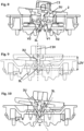
- a bistable mechanism M for switch S is shown, wherein the base 1 is made of a lower body 12 enclosing electrical contacts and comprising connection levers L.
- the lower body 12 is covered by an upper cover 11.
- the base 1 supports a key 2 rotatable with respect to the base 1 on an axis ⁇ .
- the base 1 comprises, under the key 2 and arranged parallel to the axis ⁇ , a groove V.
- groove V it is to be understood that a concavity is defined for the purposes explained below.
- This groove V has a lower end V1, this lower end V1 must be understood as the point of the groove farther from the key 2 according to a direction ⁇ 2V (represented in FIG. 9 ).
- the direction ⁇ 2V in the present specification, is the direction perpendicular to the axis of rotation in the direction of insertion of the switch in a wall, in other words in a direction that includes the centre of the switch. In FIG.9 , this direction is the projection of a symmetry plane of the mechanism.
- the mechanism 1 comprises a deformable tab 3 having an upper end 32 attached to the key 2 and a lower end 31 leaning on the groove V.
- the deformable tab 3, as shown in FIGS. 4 to 6 comprises a narrowing 33 that can be in any position of the tab between the upper end 32 and the lower end 3, so that a lower section 3L is defined that goes from the narrowing 33 to the lower end 31 of the deformable tab 3.
- an upper section 3U can defined on the tab that extends from the upper end 32 to the narrowing 33.
- This upper section 3U can have any length and even could not exist. In this case the narrowing projects directly from the key 2.
- the degree of compression of the narrowing can be adjusted by the relative distances from the axis of rotation of the key to the narrowing and the length of the lower section L3 of the tab, or in other words, the placement of the narrowing in relation to the distance ( Raxe-sup, Raxe-inf ) between the axe of rotation of the key and the narrowing and the distance ( Rgroove-sup, Rgroove-inf ) between the narrowing and the end of the groove.
- Figure 7 shows that by arranging the narrowing closer to the rotation axis of the key, less compression is achieved than by arranging it closer to the lower end of the tab, since in the latter case there is a greater overlap of the circles representing the path of the narrowing for each one of the parts, from the axis of the key to the narrowing and from the narrowing to the lower end of the tab, if they were independent.
- Figure 7 compares the degree of compression that can be achieved according to the position of the narrowing 33, that is, according to the relationship between the radius Rgroove that goes from the lower end of the groove to the narrowing and Raxe that goes from the rotation axis of the key to the narrowing.
- the intersecting arcs of the circles described by the radii Rgroove-inf and Raxe-inf represented in the lower part of the figure 7 correspond to the preferred embodiment in which the narrowing is closer to the groove than to the axis of rotation of the key 2, and gives an overlap Overlap-inf.
- the length L3 of the tab 3, between its lower end 31 and its upper end 32 and in an uncompressed state, is greater than the distance L2V between the upper end 32 of the tab and the lower end V1 of the groove V in an installed condition, so that the tab 3 constitutes a deformable element articulated in the narrowing 33. Therefore, in an installed condition, the length L3 will be shorter than in a compressed state.
- the bottom of the groove V and the lower end 31 of the tab 3 are rounded.
- the groove V is V-shaped, such that two planar surfaces V2 are defined in both sides of the groove V, the surfaces V2 forming an angle ⁇ therebetween, the angle ⁇ has a value such that in the extreme positions of the key 2, the sides of the lower section 3L of the tab 3 do not rest on the planar surfaces V2.
- V-shaped side walls are a constructive option, allowing easy centering when mounting the switch. In no case are these walls necessary for the correct operation of the deformable tab.
- the important thing for the operation of the deformable tab_ is that its end rests in a concavity.
- the extreme positions of the key will be determined by points or support surfaces on the base, coinciding with the ends of the key, to reduce pressures.
- the deformable tab 3 In abutting configurations of the key on the base, the deformable tab 3 will be in a bent configuration, but without actually touching the walls adjacent to the groove.
- the narrowing 33 is displaced with respect to the middle point of the tab 3 between the lower end 31 and the upper end 32, the upper section 3U of the tab 3 being longer that the lower section 3D of the tab 3. Nevertheless the upper section 3U of the tab 3 can have any length and even the upper section 3U could not exist at all. But the lower section 3L of the tab 3 needs to have at least a minimum length from the narrowing to the lower end 31 of the tab 3, enough to allow demoulding and to perform an automatized treatment that bends the tab in both directions such that areas of the narrowing enters a plastic zone in the tension-deformation diagram.
- the upper end 32 of the deformable tab 3 is T shaped, and the key 2 has a complementary housing 23 for the T-shaped end 32, thus providing a good anchoring of the tab in the key.
- the key 2 is made of a plate 21, and two lateral extensions 22 upwardly oriented and provided each with a circular protrusion ⁇ 1, such that the upper end 32 of the tab 3 is arranged below the axis ⁇ of rotation of the key 2.
- the base 1 has two upper extensions 13 each facing a lateral extension 22 of the key and provided with an elongated groove 14, each elongated groove having in their upper end a semicircular shape ⁇ 2 for receiving the circular protrusions ⁇ 1.
- the axis ⁇ of rotation of the key is as close as possible to the rotation of the key to reduce the gaps between the key or the key protector and an external frame of the switch. Said in other words, the central section of the key surface is not displaced in the rotation.
Landscapes
- Rotary Switch, Piano Key Switch, And Lever Switch (AREA)
Priority Applications (1)
| Application Number | Priority Date | Filing Date | Title |
|---|---|---|---|
| EP21383227.2A EP4202964A1 (fr) | 2021-12-27 | 2021-12-27 | Mécanisme bistable pour commutateur |
Applications Claiming Priority (1)
| Application Number | Priority Date | Filing Date | Title |
|---|---|---|---|
| EP21383227.2A EP4202964A1 (fr) | 2021-12-27 | 2021-12-27 | Mécanisme bistable pour commutateur |
Publications (1)
| Publication Number | Publication Date |
|---|---|
| EP4202964A1 true EP4202964A1 (fr) | 2023-06-28 |
Family
ID=79171055
Family Applications (1)
| Application Number | Title | Priority Date | Filing Date |
|---|---|---|---|
| EP21383227.2A Withdrawn EP4202964A1 (fr) | 2021-12-27 | 2021-12-27 | Mécanisme bistable pour commutateur |
Country Status (1)
| Country | Link |
|---|---|
| EP (1) | EP4202964A1 (fr) |
Citations (3)
| Publication number | Priority date | Publication date | Assignee | Title |
|---|---|---|---|---|
| US4843200A (en) * | 1986-10-29 | 1989-06-27 | Legrand | Switch Mechanism having a conductive contact arm with a double pivot |
| FR2711841A1 (fr) * | 1993-10-29 | 1995-05-05 | Arnould App Electr | Interrupteur électrique dont le balai conducteur est à double pivot. |
| US20150179372A1 (en) * | 2013-12-20 | 2015-06-25 | Erik Jeffrey Gouhl | Wiring Device with Toggle Spring Cup |
-
2021
- 2021-12-27 EP EP21383227.2A patent/EP4202964A1/fr not_active Withdrawn
Patent Citations (3)
| Publication number | Priority date | Publication date | Assignee | Title |
|---|---|---|---|---|
| US4843200A (en) * | 1986-10-29 | 1989-06-27 | Legrand | Switch Mechanism having a conductive contact arm with a double pivot |
| FR2711841A1 (fr) * | 1993-10-29 | 1995-05-05 | Arnould App Electr | Interrupteur électrique dont le balai conducteur est à double pivot. |
| US20150179372A1 (en) * | 2013-12-20 | 2015-06-25 | Erik Jeffrey Gouhl | Wiring Device with Toggle Spring Cup |
Similar Documents
| Publication | Publication Date | Title |
|---|---|---|
| CN110471561B (zh) | 触控装置 | |
| JP4988836B2 (ja) | エネルギーガイドチェーン及びその継手部材 | |
| US7816615B2 (en) | Push-switch | |
| WO2014175446A1 (fr) | Interrupteur à poussoir et module interrupteur | |
| CN113646964A (zh) | 用于二次电池的绝缘体以及包括该绝缘体的二次电池 | |
| US20180087494A1 (en) | Refrigerant compressor | |
| EP4202964A1 (fr) | Mécanisme bistable pour commutateur | |
| WO2023179726A1 (fr) | Module de touche et dispositif électronique | |
| US20010046402A1 (en) | Keyboard switch | |
| JP6632938B2 (ja) | プッシュスイッチ | |
| US9024219B2 (en) | Push switch | |
| US6534736B1 (en) | Key switch of keyboard unit | |
| JP7125492B2 (ja) | プッシュスイッチ | |
| CN101297385A (zh) | 按钮开关用弹性部件 | |
| JP2013110034A (ja) | ブレーカー | |
| US6580045B1 (en) | Switch with pivotable actuator | |
| EP4533170B1 (fr) | Ensemble charnière pour lunettes et lunettes comprenant un tel ensemble charnière | |
| JP6080702B2 (ja) | プッシュスイッチ | |
| KR101839820B1 (ko) | 푸시버튼 스위치 | |
| KR200162410Y1 (ko) | 2축형 키이보오드 스위치 | |
| TWI233133B (en) | Push-button switch | |
| EP4533171A1 (fr) | Ensemble charnière pour lunettes intelligentes et lunettes intelligentes comprenant un tel ensemble charnière | |
| US6797904B1 (en) | Microswitch | |
| JP2022178190A (ja) | サーモスタット | |
| EP4567844A1 (fr) | Bouton-poussoir |
Legal Events
| Date | Code | Title | Description |
|---|---|---|---|
| PUAI | Public reference made under article 153(3) epc to a published international application that has entered the european phase |
Free format text: ORIGINAL CODE: 0009012 |
|
| STAA | Information on the status of an ep patent application or granted ep patent |
Free format text: STATUS: THE APPLICATION HAS BEEN PUBLISHED |
|
| AK | Designated contracting states |
Kind code of ref document: A1 Designated state(s): AL AT BE BG CH CY CZ DE DK EE ES FI FR GB GR HR HU IE IS IT LI LT LU LV MC MK MT NL NO PL PT RO RS SE SI SK SM TR |
|
| STAA | Information on the status of an ep patent application or granted ep patent |
Free format text: STATUS: THE APPLICATION IS DEEMED TO BE WITHDRAWN |
|
| 18D | Application deemed to be withdrawn |
Effective date: 20240103 |