EP4203204A1 - Connexion de barre omnibus - Google Patents
Connexion de barre omnibus Download PDFInfo
- Publication number
- EP4203204A1 EP4203204A1 EP21217325.6A EP21217325A EP4203204A1 EP 4203204 A1 EP4203204 A1 EP 4203204A1 EP 21217325 A EP21217325 A EP 21217325A EP 4203204 A1 EP4203204 A1 EP 4203204A1
- Authority
- EP
- European Patent Office
- Prior art keywords
- terminal
- collar
- electrical connector
- hole
- hollow portion
- Prior art date
- Legal status (The legal status is an assumption and is not a legal conclusion. Google has not performed a legal analysis and makes no representation as to the accuracy of the status listed.)
- Pending
Links
Images




Classifications
-
- H—ELECTRICITY
- H01—ELECTRIC ELEMENTS
- H01R—ELECTRICALLY-CONDUCTIVE CONNECTIONS; STRUCTURAL ASSOCIATIONS OF A PLURALITY OF MUTUALLY-INSULATED ELECTRICAL CONNECTING ELEMENTS; COUPLING DEVICES; CURRENT COLLECTORS
- H01R4/00—Electrically-conductive connections between two or more conductive members in direct contact, i.e. touching one another; Means for effecting or maintaining such contact; Electrically-conductive connections having two or more spaced connecting locations for conductors and using contact members penetrating insulation
- H01R4/26—Connections in which at least one of the connecting parts has projections which bite into or engage the other connecting part in order to improve the contact
-
- H—ELECTRICITY
- H01—ELECTRIC ELEMENTS
- H01R—ELECTRICALLY-CONDUCTIVE CONNECTIONS; STRUCTURAL ASSOCIATIONS OF A PLURALITY OF MUTUALLY-INSULATED ELECTRICAL CONNECTING ELEMENTS; COUPLING DEVICES; CURRENT COLLECTORS
- H01R4/00—Electrically-conductive connections between two or more conductive members in direct contact, i.e. touching one another; Means for effecting or maintaining such contact; Electrically-conductive connections having two or more spaced connecting locations for conductors and using contact members penetrating insulation
- H01R4/28—Clamped connections, spring connections
- H01R4/30—Clamped connections, spring connections utilising a screw or nut clamping member
- H01R4/34—Conductive members located under head of screw
-
- H—ELECTRICITY
- H01—ELECTRIC ELEMENTS
- H01R—ELECTRICALLY-CONDUCTIVE CONNECTIONS; STRUCTURAL ASSOCIATIONS OF A PLURALITY OF MUTUALLY-INSULATED ELECTRICAL CONNECTING ELEMENTS; COUPLING DEVICES; CURRENT COLLECTORS
- H01R43/00—Apparatus or processes specially adapted for manufacturing, assembling, maintaining, or repairing of line connectors or current collectors or for joining electric conductors
- H01R43/26—Apparatus or processes specially adapted for manufacturing, assembling, maintaining, or repairing of line connectors or current collectors or for joining electric conductors for engaging or disengaging the two parts of a coupling device
-
- H—ELECTRICITY
- H01—ELECTRIC ELEMENTS
- H01R—ELECTRICALLY-CONDUCTIVE CONNECTIONS; STRUCTURAL ASSOCIATIONS OF A PLURALITY OF MUTUALLY-INSULATED ELECTRICAL CONNECTING ELEMENTS; COUPLING DEVICES; CURRENT COLLECTORS
- H01R13/00—Details of coupling devices of the kinds covered by groups H01R12/70 or H01R24/00 - H01R33/00
- H01R13/02—Contact members
- H01R13/03—Contact members characterised by the material, e.g. plating, or coating materials
-
- H—ELECTRICITY
- H01—ELECTRIC ELEMENTS
- H01R—ELECTRICALLY-CONDUCTIVE CONNECTIONS; STRUCTURAL ASSOCIATIONS OF A PLURALITY OF MUTUALLY-INSULATED ELECTRICAL CONNECTING ELEMENTS; COUPLING DEVICES; CURRENT COLLECTORS
- H01R4/00—Electrically-conductive connections between two or more conductive members in direct contact, i.e. touching one another; Means for effecting or maintaining such contact; Electrically-conductive connections having two or more spaced connecting locations for conductors and using contact members penetrating insulation
- H01R4/06—Riveted connections
Definitions
- the present invention relates to an electrical connector, an electrical connector system, a first element for an electrical connector, a method of assembling an electrical connector and a method of connecting an electrical connector to a counter connector.
- the present invention relates to support electrical connection by an electrical connector comprising a terminal and an element.
- busbars are well known in the art. They are used for conducting electrical power, particularly for conducting high electrical current, potentially in regimes of high voltages. With the emerging numbers of electric vehicles, such as electric cars, busbar are increasingly used in the automotive sector. For instance, busbars are used to provide an electrical connection between a vehicle's drive, a vehicle's battery and/or a charging unit. In addition, further industry sectors are subject to a drastic increase in the number of electrical components. For instance, the air traffic sector is facing a paradigm shift to all-electric-aircrafts, wherein controls are performed mostly electrically. In general, any evolving technology relies at least in some part of electrical power transmission and thus requires electrical connection.
- busbars have to be connected to further parts, such as a further busbars, busbar portions and/or terminals.
- the busbar may be connected to a terminal of the vehicle's drive, battery and/or charging unit.
- an object of the present invention to overcome some or all of the deficiencies of the prior art.
- It is a further object to improve the impediment that could arise by contact corrosion, high or low temperature environments, dusty environments or environments that are subject to any foreign matter and/or particles.
- an electrical connector an electrical connector system, a first element for an electrical connector, a method for assembling an electrical connector and a method for connecting an electrical connector to a counter connector according to the independent claims.
- Preferred aspects are subject of the dependent claims, and the skilled person finds hints for other suitable aspects of the present invention through the overall disclosure of the present application.
- an electrical connector for connecting a conductive element to a counter connector, which comprises a terminal, of the conductive element, having a first surface and defining a through-hole in the first surface extending through the terminal.
- the electrical connector further comprises a first element separate from the terminal and in engagement with the terminal, wherein the first element comprises a hollow portion extending through the through-hole of the terminal and a collar covering at least a part of a periphery of the through-hole on the first surface of the terminal, wherein a main surface of the collar facing the first surface of the terminal is structured such that rotation of the element in the through-hole is prevented.
- the terminal could be a part of a conductive element, a busbar, a busbar portion or anything that can carry electrical current, and which is to be connected to another part, e.g. a counter connector.
- the terminal has a through-hole, which could be a recess on the first surface. This through hole may be extending through the terminal and may have the shape of an empty cylinder, but also other shapes are possible.
- the separate first element is another part that engages with the terminal. It may be fixed, attached or somehow connected to the terminal, preferably it is substantially rigidly fixed to the terminal. This beneficially provides for electrical current from the terminal to the first element.
- the first element further has a hollow portion that extends through the through-hole of the terminal.
- this hollow portion has the shape of a cylinder, but also other shapes are possible.
- the shape of the outer surface of the hollow portion is similar or equal to the shape of the through-hole. This advantageously provides for a proper positioning within the through-hole.
- the collar covers at least a part of a periphery of the through-hole. This periphery could be the circumference of the through-hole on the first surface but also this periphery is not limited to this and can also be a surface, preferably a ring circle around the through-hole on the first surface.
- the main surface of the collar that faces the first surface of the terminal is structured to substantially prevent rotation of the element in the through-hole.
- This rotation could be understood as a rotation around a longitudinal axis along the hollow portion of the first element, which may be substantially perpendicular to the first surface of the terminal and which may be parallel to a longitudinal axis of the through-hole.
- the element is maintained in its position, for instance if a rotating force acts on it, which could be the case if a screw nut was rotated while touching the first element. This could be the case if the electrical connector was to be connected to a counter connector by a screw.
- By preventing rotation of the element its position is beneficially maintained during any screwing process.
- this first element prevents any mistakes during setup of an electrical connection of an electrical connector to a counter connector. Thereby, assembling is improved and simplified.
- the electrical connection does not require expensive welding of a conductive element, such as a busbar portion to other parts. Thereby, assembling is facilitated because users do not require extensive teaching.
- the through-hole has an axis along the direction of the through-hole which may be substantially perpendicular to the first surface of the terminal and thereby also to the main surface of the collar.
- the main surface of the collar that is facing the first surface of the terminal is structured along a circumferential direction of the collar.
- a structure of the main surface along a circumferential direction is provided.
- This structure could be uniformly or non-uniformly.
- the circumferential direction of the collar is a direction around and perpendicular to a longitudinal direction of the hollow portion.
- this circumferential direction is the direction in which rotation is prevented by way of the structure of the main surface.
- This provides the benefit that the structure can easily be manufactured by appropriate machines. Further, it improves that a rotation of the element is prevented.
- Having such a structured main surface of the collar could mean for instance that a circular ring, forming part of the main surface, is structured, i.e. it could have elevations and dimples or grooves in the circumferential direction of the collar. Thus, it may a certain structure.
- the main surface has a non-unitary structure in a circumferential direction. This non-unitary structure could further improve preventing a rotation.
- the first element further comprises at least one protrusion on the main surface of the collar.
- This protrusion is located on the main surface of the collar and is preferably directed towards or faces the first surface of the terminal. This is to be understood that, for instance if the protrusion has an elongate or pointed shape, the axis of elongation or the direction, in which the pointed shape points is substantially perpendicular to the first surface of the terminal.
- the protrusion could be located anywhere on the main surface and amounts to its structured characteristic.
- the protrusion could be anything that extends from the main surface of the collar towards the first surface of the terminal. It could be for instance a bump, preferably it has a pointed or sharper tip.
- the at least one protrusion could have a tapered shape, an elongated shape, a cylindrical shape, a cubic shape, a cuboid shape, a pointed shape, a conical and/or a pyramidical shape or combinations thereof.
- the at least one protrusion comprises a tip portion and a base portion, wherein the tip portion is facing the terminal and the base portion is opposite of the tip portion and located on the main surface of the collar, wherein a peripheral dimension of the tip portion is smaller than a peripheral dimension of the base portion.
- the peripheral dimension could be for instance a circumference. If the protrusion is a conical cylinder, the top circumference would thus be smaller than the bottom circumference.
- the top circumference of the cylinder is a peripheral dimension of the top portion and the bottom circumference of the cylinder is a peripheral dimension of the base portion.
- the at least one protrusion is pressed at least partially into the terminal, wherein at least 5 % of a height of the at least one protrusion extending from the main surface of the collar is pressed into the terminal, preferably at least 10%, more preferably at least 40%, even more preferably at least 60%, even more preferably at least 80%, most preferably 100% of the height of the at least one protrusion.
- the height could be measured from a tip portion to a bottom portion of the protrusion.
- the height is measured from a part of the tip portion of the protrusion that has the furthest distance to the base portion, preferably wherein the distance is perpendicular to the main surface.
- the at least one protrusion is pressed into the terminal, preferably the protrusion is pressed completely, that is to about 100% of its height into the terminal. This bears the potential that a great contact area is provided for the electrical current to flow from the terminal to the element. Further, any oxidation that might be present on the terminal or busbar portion, on which the element could be connected, in particular any oxidation of the first surface of the terminal is thus broken and electrical current can flow beneficially.
- the element can be used as for instance a substantially mechanical fixed bushing.
- the protrusion also improves that a rotation of the element is prevented. It could be said that a further pressing of the protrusion into the terminal, provides for an even better prevention of a rotation. Further, pressing the protrusion into the terminal substantially prevents any dirt or dust from outside to penetrate into a gap that could be formed between the first surface of the terminal and the main surface of collar. Thus, corrosion is beneficially prevented.
- the at least one protrusion has a height of at least 0.2 mm, preferably at least 0.4 mm, more preferably at least 0.6 mm, even more preferably at least 0.8 mm, most preferably of at least 1.0 mm; and/or wherein the at least one protrusion has a height of at most 15 mm, preferably at most 8 mm, more preferably at most 5 mm, even more preferably at most 3 mm, most preferably of at most 1 mm.
- the height may be measured as described above.
- a greater height of the protrusion may provide for an even better advantage with respect to breaking an oxidation layer of the terminal and preventing a rotation of the first element.
- a greater height may be difficult to manufacture.
- the heights could also be understood relative to other dimensions of the element. For instance, if a diameter of the collar was defined as being 100%, then the protrusion could have a height of at least 0.5%, preferably at least 1%, more preferably at least 2%, most preferably of at least 4% of that diameter. Further, the at least one protrusion could have a height of at most 10%, preferably at most 8%, more preferably at most 6%, most preferably of at most 5% of that diameter.
- the first element comprises a plurality of protrusions on the main surface of the collar, wherein the plurality of protrusions is preferably distributed equally on the main surface of the collar facing the first surface of the terminal.
- the plurality of protrusions could comprise any number of protrusions of at least 2, preferably of at least 5, more preferably of at least 10, even more preferably of at least 20, most preferably of at least 40. Further, the plurality of protrusions could comprise any number of protrusions of at most 200, preferably of at most 150, more preferably of at most 100, even more preferably of at most 80, most preferably of at most 60. A higher number of protrusions can provide for an even better effect in terms of preventing any rotation of the element and for breaking an oxidation layer of the terminal. Thus, electrical connection between the terminal and the first element is further improved and assembling this electrical connector to other parts by way of a screw is facilitated and simplified.
- a size of M2, M4, M6, M8 or M10 representing diameters of the screw of 2 mm to 10 mm respectively, may be used.
- M6 or M8 screws may be employed.
- the number of protrusions that are comprised may also depend on the size of the screws used. It may be the case that, if larger screws were used, the number of protrusions is beneficially increased.
- the plurality of protrusions may also advantageously provide for a pattern on the main surface of the collar, wherein the pattern has the appearance of elevations and lowerings or elevations and sinkings. This beneficially provides for improved prevention of rotation of the element, for instance if a force acts on the element in an attempt to rotate the element. Thus, the element is physically stabilized better at its location. Further, breaking an oxidation layer of the terminal may be improved by the pattern.
- a material of the first element is harder than a material of the terminal, preferably a material of the first element has a Brinell hardness number which is larger by at least 10%, preferably by at least 30%, more preferably by at least 80%, even more preferably by at least 140%, further even more preferably by at least 200%, most preferably by at least 300% as compared to the Brinell hardness number of a material of the terminal.
- the Brinell hardness number of the first element is larger by at least 30% than the Brinell hardness number of the terminal, this means that if the terminal is of pure aluminum, having a Brinell hardness of 15 HB, then the first element has 19,5 HB. If may also be possible that the hardness is measured according to the Rockwell or Vickers scale.
- the protrusions can beneficially be better pressed into the terminal.
- the protrusions preferably comprise the same material as the element.
- the protrusions do not substantially deform from a first state before they are pressed into the terminal with respect to a second state after they are pressed into the terminal to form an electrical connector.
- the terminal has a second surface opposite of the first surface and wherein the through-hole extends through the terminal from the first surface to the second surface.
- the connector further comprises a second element separate from the terminal and the first element, the second element having a hollow portion received within the hollow portion of the first element, wherein the second element has a collar covering at least a part of a periphery of the through-hole on the second surface of the terminal.
- the through-hole may substantially form an empty cylinder within the terminal and connects the first and the second surface of the terminal.
- the first and the second surface of the terminal could be substantially parallel to each other.
- the through-hole has an axis along the direction of the through-hole, wherein the axis maybe substantially perpendicular to the first surface of the terminal.
- the axis of the through hole may be substantially perpendicular to the second surface of the terminal.
- the second element has a collar similar to the collar of the first element and it covers a periphery of the through-hole, such as a circumference of the ring surface around the through-hole on the second surface. This provides the benefit that the second element can be connected to the terminal and further supports transmission of electrical power by way of an increased surface area.
- the outer surface of the hollow portion of the second element and the inner surface of the hollow portion of the second element preferably have a cylindrical shape, however different shapes are possible as described with reference to the hollow portion of the first element.
- an outer surface of the hollow portion of the second element is in form-fit connection with the inner surface of the hollow portion of the first element.
- the outer surface of the hollow portion of the second element and the inner surface of the hollow portion of the first element have a cylindrical shape.
- the second element could also have protrusions as described with reference to the first element.
- the protrusions of the second element are located on a main surface of the collar of the second element facing the second surface of the terminal. This further enhances to prevent any rotation of the first and the second element and further improves breaking an oxidation layer of the terminal and thereby facilitates electrical connection.
- An 11th embodiment of this invention is directed to an electrical connector system, comprising an electrical connector according to any one of the embodiments 1 to 10 and a counter connector.
- the electrical connector system further comprises fixing means, optionally a screw, extending through the hollow portion of the first element and fixing the electrical connector to the counter connector.
- an electrical connection of the terminal to a counter connector is provided in a simple and easy way. Assembling of the electrical connector to a counter connector is improved, because the elements are substantially rigidly connected to the terminal and rotation is prevented. This is also the case if a screw nut was used to fix a screw on the first or second element.
- An 12th embodiment of this invention is directed to a first element for facilitating an electrical connection of a conductive element to a counter connector.
- the first element comprises a hollow portion extending along a longitudinal axis and having two opposite ends on the longitudinal axis; a collar extending perpendicular to the longitudinal axis from one end of the first element, the collar having a main surface facing towards a second end of the first element along the longitudinal axis; at least one protrusion, preferably a plurality of protrusions, on the main surface of the collar; wherein the main surface of the collar is structured along a circumferential direction of the collar, preferably wherein the at least one protrusion comprises a tip portion and a base portion, wherein the tip portion is facing the second end and the base portion is opposite of the tip portion and located on the surface of the collar, wherein a peripheral dimension of the tip portion is smaller than a peripheral dimension of the base portion.
- the first element beneficially supports to electrically connect two parts to each other, for instance a terminal to a counter connector as described above.
- the first element of this embodiment can comprise all aspects that were mentioned with respect to the first and/or second element of the previous embodiments.
- this first element it can be beneficially used to provide an assembly of an electrical connector, wherein substantially rotation of the element with respect to a longitudinal axis of the hollow portion is prevented.
- a 13th embodiment of this invention is directed to a method of assembling an electrical connector, the method comprising the steps of:
- the deformation of the first element provides for a proper fixation of the first element to the terminal.
- the deformation could be established by pressing means, such as a clinching mandrel, which is removed after deforming the first element.
- the connection is established by press-fitting the first element to the terminal.
- the method further comprises the steps of:
- a second element is beneficially provided, which improves a connection of the first and second element to the terminal.
- the aspects mentioned with reference to the terminal and the first element are also applicable to the terminal and the second element of the method of this embodiment.
- the second element could also have all the features as described with reference to the first element, e.g. it could have protrusions on the main surface of the collar.
- the second element is inserted into the through-hole.
- the hollow portion of the second element overlaps with the hollow portion of the first element. Even more preferably, the hollow portion of the second element extends completely through the hollow portion of the first element.
- a rotation of the first and the second element is beneficially prevented.
- a 15th embodiment of this invention is directed to a method of connecting an electrical connector to a counter connector, the method comprising the steps of:
- a method for connecting an electrical connector to a counter connector is provided. in a simple and easy way.
- This method provides for a simplified assembling of the electrical connector to a counter connector. Further, this method does not require welding, which could be expensive, to connect a terminal to a counter connector. Further, the elements provide for improved electrical contact, by breaking an oxidation layer of the terminal. Further, the elements to not move during assembling of the fixing means, such as a screw. This in particular is advantageous if this method was performed in different environments that are subject to vibration, or where access to the electrical parts to be connected is not easy.
- a size of M2, M4, M6, M8 or M10 representing diameters of the screw of 2 mm to 10 mm respectively, may be used. However, also larger or smaller screws may be employed. Preferably M6 or M8 screws may be employed.
- Fig. 1A shows an electrical connector 1 according to an embodiment of the invention, which comprises a terminal 10 and a first element 20 that is separate from the terminal.
- the terminal 10 has a first surface 11, and the terminal has a through-hole 15 on the first surface 11.
- the through-hole extends through the terminal.
- the terminal could be for instance part of a conductive element such as a busbar or anything that is suitable for carrying electrical current and which should be electrically connected to another part to transfer electrical power.
- the terminal is a portion of a busbar which is to be electrically connected to another terminal, part, busbar or the like.
- the first element 20 is made of aluminum or copper alloy material and the terminal 10 is made of aluminum.
- the material of the first element 20 is harder than the material of the terminal 10.
- the second element 30 is made of aluminum or copper alloy and is harder than the material of the terminal 10.
- the first element 20 and the second element 30 (if available) is treated by plating to be substantially safe from oxidation.
- plating is an oxidation-reduction reaction, where one material gives up electrons and the other material gains electrons.
- the first element 20 has a hollow portion 21, which has an outer and an inner surface in the shape of a cylinder.
- each of the outer and inner surface has the shape of a cylinder.
- the outer and an inner surface of the hollow portion could also have different shapes.
- the shape of the outer and inner surface deviates slightly from a cylinder, for instance the shape is a rounded shape. In another example of this embodiment, they have a shape corresponding to a slotted hole.
- This hollow portion 21 extends through the through-hole 15, such that it is inserted into the through-hole.
- the through-hole has the shape of a cylindrical hole or cavity, in which the material of the terminal is not present.
- the outer surface of the hollow portion is in substantially direct vicinity of the through-hole, i.e. the cylindrical hole of the terminal. For instance, the outer surface of the hollow portion could be in contact and/or in form-fit with the through-hole.
- the first element 20 further comprises a collar 25, which extends radially in a perpendicular direction to the longitudinal direction of the hollow portion.
- This collar is located on one end of the first element 20 and covers a periphery of the through-hole on the first surface of the terminal.
- the collar has a main surface 26 that faces the first surface 11 of the terminal. This main surface 26 of the collar 25 is structured such that rotation of the first element 20 in the through-hole 15 is prevented.
- the first element 20 could resist this rotation and beneficially maintains its position. Thereby, damage of the first surface of the terminal 10 and/or the surface of the collar facing the first surface of the terminal 10 is prevented. This damage could lead to corrosion and thus adversely affect an electrical contact. Thus, corrosion is alleviated by that.
- the first element 20 further comprises at least one protrusion 50 on the surface of the collar 21 facing the first surface 11.
- This protrusion is at least partially pressed into the terminal.
- the protrusions can penetrate through an oxide layer of the surface of the first element 20 and thereby further enhance electrical contact between the terminal and the first element 20.
- This protrusion also supports that a rotation of the first element 20 is prevented in case a rotating force acts on the first element 20. This could for instance be the case if the first element 20 is to be brought in electrical contact with a counter connector and screws were used to connect the terminal with the first element 20 to the counter connector. These screws could entail a rotating force on the first element 20.
- the protrusions can comprise a plurality of protrusions.
- Fig. 1B shows an electrical connector 1 according to the embodiment of the invention of Fig. 1A in a side view.
- a multitude of protrusions 50 are shown.
- the protrusions are pressed into the terminal along their total height or length of a base portion to the tip portion of the protrusion. They are pressed through the first surface 11 of the terminal along a longitudinal direction 22 of the hollow portion of the first first element 20.
- the outer surface of the hollow portion of the first element 20 is in form-fit with the inner surface of the through-hole.
- Fig. 2 shows an electrical connector 1 according to an embodiment of the invention, which comprises a terminal and a first element 20 that is separate from the terminal.
- the terminal could be for instance a part of a conductive element such as a busbar or anything that is suitable for carrying electrical current and which should be electrically connected to another part to transfer electrical power.
- the terminal is a portion of a busbar which is to be electrically connected to another terminal, part, busbar or the like.
- This embodiment further comprises a second element 30, that is separate from the terminal 10 and the first element 20.
- the first element 20 and the second element 30 are made of aluminum or copper alloy material and the terminal 10 is made of aluminum.
- the material of the first element 20 and the second element 30 is harder than the material of the terminal 10.
- the terminal 10 has a first surface 11, and a second surface 12 opposite of the first surface 11 and a through-hole 15, which extends through the terminal 10 from the first surface 11 to the second surface.
- This through-hole is a through hole extending through the material of the terminal.
- the first element 20 is similar to the first element 20 as described in an embodiment with reference to Fig. 1A and comprises protrusions 50 on the main surface 26 of the collar 25 facing the first surface 11 of the terminal 10.
- the second element 30 has a hollow portion 31 that is received within the hollow portion 21 of the first element 20.
- the hollow portion of the second element has an outer and an inner surface in the shape of a cylinder. The outer and an inner surface of the hollow portion of the second element could also have different shapes.
- the second element has a collar, which extends radially in a perpendicular direction to the longitudinal direction of the hollow portion of the hollow portion of the second element.
- the collar of the second element covers a periphery of the through-hole on the second surface of the terminal.
- the hollow portion of the second element is in form-fit connection with the inner surface of the hollow portion of the first element.
- the first element, the second element and the terminal are connected to each other. This could be done for instance like connections of two rivets to another part.
- the first element 20, the second element 30 and the terminal 10 are connected to each other such that the at least one protrusion or the plurality of protrusions of the surface of the collar of the first element are at least partially pressed into the terminal.
- the protrusions are pressed along their total length into the terminal. The length of a protrusion of the first element is measured from an outermost point of a protrusion to the surface of the collar substantially in a parallel direction towards the longitudinal axis of the hollow portion of the first element.
- Fig. 3 shows an electrical connector 1 according to an embodiment of the invention, which comprises a terminal and a first element 20 that is separate from the terminal.
- the terminal could be for instance a part of a conductive element such as a busbar or anything that is suitable for carrying electrical current and which should be electrically connected to another part to transfer electrical power.
- the terminal is a portion of a busbar which is to be electrically connected to another terminal, part, busbar or the like.
- the first element is similar to the first element as described in an embodiment with reference to Fig. 1A and Fig. 2 and comprises protrusions on the side of the collar facing the first surface of the terminal.
- the second element is similar to the second element as described in an embodiment with reference to Fig.
- protrusions on the side of the collar facing the second surface of the terminal are pressed along their total length into the terminal.
- the length of a protrusion of the second element is measured from an outermost point of a protrusion to the surface of the collar substantially in a parallel direction towards the longitudinal axis of the hollow portion of the second element.
- all protrusions of the first element and the second element are pressed into the terminal.
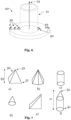
- Fig. 4 shows on the left side a disassembled electrical connector according to an embodiment of the invention, which comprises a terminal and a first element that is separate from the terminal and a second element that is separate from the terminal. The first and second element are shown apart from the terminal in a state prior to assembly for illustrative purposes
- Fig. 4 shows on the right side an electrical connector 1 according to an embodiment of the invention, which comprises a terminal and a first element that is separate from the terminal and a second element that is separate from the terminal.
- Fig. 5A shows an element 20, 30 for an electrical connector according to an embodiment of the invention.
- This element 20, 30 can be a first element 20 or a second element 30. In this example it is referred to as the first element 20.
- This element 20 could be used for instance as an element in the embodiments shown in previous Figures.
- the element has a hollow portion extending along a main axis and a collar extending perpendicular to the main axis from one end of the element.
- the collar has a surface facing the second end of the element.
- the surface of the collar is structured nonuniformly along a circumferential direction and the element further comprises at least one protrusion on the surface of the collar.
- the hollow portion has an outer and an inner surface in the shape of a cylinder.
- the element has a plurality of protrusions on the surface of the collar. These protrusions all have substantially the same shape and are positioned substantially in an equidistant manner.
- the protrusions have a tip portion and a base portion, wherein the tip portion is facing the second end and the base portion is opposite of the tip portion and located on the surface of the collar. In this embodiment the distance from the tip to the base portion is a length of the protrusion and is about 1 mm.
- the size of the length of the protrusion 50 depends on the overall size of the element and could be greater if the element is greater.
- Fig. 5B shows an element 30, 20 for an electrical connector according to an embodiment of the invention.
- This element 20, 30 can be a first element 20 or a second element 30. In this example it is referred to as the second element 30.
- This second element 30 is similar to the first element 20 as described in an embodiment with reference to Fig. 5A .
- the second element 30 comprises a different hollow portion as compared to the embodiment of Fig. 5A .
- the hollow portion has an outer diameter of the hollow portion that is not greater than an inner diameter of the hollow portion of the embodiment in Fig. 5A , i.e. the first element 20. This facilitates that the hollow portion of the second element 30 can be received within the hollow portion of the first element 20 in the embodiment of Fig. 5A .
- Fig. 6 shows an element 20, 30 for an electrical connector according to an embodiment of the invention.
- This element 20, 30 can be a first element 20 or a second element 30.
- different locations of the at least one protrusion 50 on the surface of the collar of the element are exemplarily shown. However, further locations are also possible.
- the surface of the collar faces the opposite, i.e. the second end of the element.
- the at least one protrusion can be positioned at an outer region of the surface of the collar and/or at an inner region of the surface of the collar and/or in the middle thereof.
- the protrusion of this example is depicted as a having pyramid portion or pyramid shape. However, different shapes or also possible.
- the tip portion of the protrusion i.e.
- the tip of the pyramid in one example is facing in the direction of the second end of the element in the examples on the left side of collar in Fig. 6 .
- an exemplary protrusion is shown having a pyramid portion or shape, wherein the tip of the pyramid is facing a radial outer direction, substantially perpendicular to a longitudinal axis 22 of the hollow portion 21 of the element 20, 30. This exemplary protrusion is still contacting the surface of the collar facing the second end of the element.
- a protrusion having a cylindrical portion or shape is also depicted in Fig. 6 on the outer region of the surface of the collar on the right side.
- protrusion 6 shows a multitude of protrusions, not all of these must be present, i.e. not all of these must be comprised by the element. At least one protrusion is comprised in this embodiment. However, also combinations of the depicted protrusions, their portions or shapes and their locations are possible.
- Fig. 7 shows different shapes of protrusions according to an embodiment of the invention. These different shapes of protrusions can be applied for any protrusion used in any embodiment of the invention and the examples shown in Fig. 7 are not limiting.
- the illustrated shapes of protrusions are just examples and further shapes are also possible.
- Example a) shows a pyramid shape. Reference signs are applied to example a) and are to be understood equally present in the remaining examples.
- the protrusion 50 has a base portion 51 and a tip portion 52. As can be seen in example a), a peripheral dimension of the tip portion 52 is smaller than a peripheral dimension of the base portion 51.
- a peripheral dimension of the base portion 51 is the length of the circumference of the base portion 51 and a peripheral dimension of the tip portion 52 is the length of the circumference of the tip portion 52.
- the pyramid in example a) can have a square ground surface forming part of the base portion 51, i.e. a surface having four corners, such as a rectangular or quadradic surface.
- different ground surfaces are also encompassed, such as a triangle, pentagon, hexagon, heptagon and octagon.
- the shape is a tetrahedron.
- example b) shows a pyramid shape with 5 corners of the ground surface that can be seen from this perspective.
- the examples a) and b) can also have a plurality of corners on the ground surface.
- the pyramid shapes can also have a flatter tip as compared to the illustrated tip.
- Example c) shows a cylindrical shape.
- Example d) shows a conical shape.
- Example e) shows one of many examples of a tapered shape.
- a protrusion can also have a combination of the illustrated shapes.
- one specific shape may be referred to as a portion of the protrusion.
- example f comprises a cylindrical portion and a conical portion.
- the base portion 51 and the tip portion 52 of the protrusion 50 are still referred to with respect to the overall protrusion 50 and not with respect to the cylindrical portion and the conical portion.
- the height or length of the protrusion is indicated in Fig. 7 with reference sign 53. Then a surface has such protrusions, as shown in Fig. 7 , according to an embodiment of the invention those can be pressed into a terminal to a degree of 100% of the height 53.
- Fig. 7B shows an electrical connector system 500 according to an embodiment of the invention.
- An electrical connector 1 is shown a counter connector 100.
- fixing means 200 are shown that connect the electrical connector 1 and the counter connector 100.
- a screw 200 is used that extends through the hollow portion of the second element 30 and thereby also through the hollow portion of the first element 20 and through the through-hole.
- a screw nut 210 fixes one end of the screw, i.e. the bottom end in the Fig. 7B .
- a M6 screw is employed.
- a M8 screw is employed.
- the electrical connector 1 is in physical contact with the counter connector 100.
- the transmission of electrical power from the terminal 10 to the counter connector 100 by way of the first element 20 and/or the second element 30 is beneficially ensured.
- a multitude of protrusions e.g. 20 to about 60 protrusions, are applied to the main surface of the collar of the first element 20 and/or the second element 30. All of which beneficially provide for electrical contact by being pressed into the terminal 10.
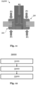
- Fig. 8 shows a flow diagram of the method for connecting a first element 20 to a terminal 10 to provide an electrical connector according to an embodiment of the invention.
- the method 1000 comprises the steps of providing a terminal 1100, which has a first surface and a through-hole on the first surface, which extends through the terminal.
- a first element configured as described above, for instance according to the embodiment of Fig. 6 .
- the first element is inserted into the through-hole from the first surface side.
- step 1400 the first element is deformed and thereby pressed into the terminal by pressing means. This is done by inserting a clinching mandrel into the hollow portion of the first element.
- any other suitable pressing means such as rods, would work.
- the clinching mandrel has a bigger diameter than the inner diameter of the hollow portion of the first element.
- the first element is pressed along the longitudinal axis of the hollow portion of the first element against the terminal, e.g. by deformation.
- the first element is connected to the terminal.
- the protrusions of the surface of the collar are thereby also pressed into the terminal.
- the first element is also deformed by the forces of the clinching mandrel that are acting upon it. Due to the deformation, a proper clamping force between the first element and the terminal is established.
- the terminal is hold in position by means that provide a counter-force, that acts on the opposite side to the first surface of the terminal where the through-hole is located.
- Fig. 9 shows a flow diagram of the method for connecting two elements, i.e. a first element 20 and a second element 30 to a terminal to provide an electrical connector according to an embodiment of the invention.
- the method 2000 comprises the steps of providing a terminal 2100, which has a first surface, and a second surface opposite of the first surface and a through-hole, which extends through the terminal from the first surface to the second surface.
- a first element 20 and a second element 30 are provided.
- the first element 20 is configured as described above, for instance according to the embodiment of Fig. 6 .
- the second element can also be configured as described above, for instance according to the embodiment of Fig. 6 .
- the second element does not necessarily have to have the at least one protrusion on the surface of the collar facing the terminal.
- step 2300 the first element 20 is inserted into the through-hole from the first surface side and the second element 30 is inserted into the through-hole from the second surface side. Thereby the outer surface of the hollow portion of the second element 30 is brought in close contact or in close vicinity to the inner surface of the hollow portion of the first element 20. Thus, they overlap within the through-hole.
- step 2400 the first element 20 and the second element 30 are deformed and thereby pressed into the terminal by pressing means. This is done by inserting a clinching mandrel into the hollow portion of the second element 30.
- any other suitable pressing means such as rods would work as well.
- This clinching mandrel has a bigger diameter than the inner diameter of the hollow portion of the second element 30.
- the second element 30 is pressed along the longitudinal axis of the hollow portion of the second element 30 and against the element, e.g. by deformation.
- the first element 20 and the second element 30 are connected to the terminal.
- the protrusions of the surface of the collar of the first element 20 are thereby also pressed into the terminal, e.g. through the first surface.
- the second element 30 comprises protrusions
- these are also pressed into the terminal, e.g. through the second surface.
- the second element 30 and the first element 20 are deformed by the forces of the clinching mandrel that are acting upon the second element 30 and thereby also on the first element 20. Due to the deformation, a proper clamping or clinching force between the first element 20, the second element 30 and the terminal is established.
- the terminal is hold in position by means that provide a counter-force, that acts on the opposite side to the insertion side of the clinching mandrel, i.e. this counter-force acts on the collar of the first element 20.
- the through-hole has the shape of a cylindrical hole and the hollow portions have a cylindrical outer and inner surface.
- the material of the first and/or second element 30 is harder than the material of the terminal.
- the terminal is a busbar made of Aluminum and the elements are made of aluminum or copper alloy, which is treated by platting to be safe from oxidation.
- Fig. 10 shows part of step 2400 of the method described above.
- the clinching mandrel is pressed into the second element 30 along the longitudinal direction of the hollow portion of the first element 20.
- the overlapping region of the hollow portions of the first and second element 30 extends along the overall length of the hollow portion of the first element 20.
- Fig. 11 shows another part of step 2400 of the method described above.
- the clinching mandrel is pressed with force F2 into the second element 30 along the longitudinal direction of the hollow portion of the second element 30 and thereby creates a force in the radial outer direction that deforms the second element 30 and further presses it against the first element 20, which deforms as well.
- Force F1 acts as a force to press the protrusions into the terminal and acts on the top and is directed downward in a vertical direction. This could be achieved for instance by providing a counter force F1 acting at the bottom and being directed upwards in a vertical direction as indicated in Fig. 11 , i.e. at the element 20.
- the element 20 could for instance be supported by laying on a ground, or table, thereby providing a corresponding counter force F1 being directed downward in a vertical direction.
- the force F1 acting on the top and being directed downward in a vertical direction as indicated in Fig. 11 may be a force additional to the force F2, i.e. for instance by separate pressing means or by way of the clinching mandrel that provides for this force in the downward vertical direction.
- Fig. 12 shows a flow diagram of the method for connecting an electrical connector to a counter connector according to an embodiment of the invention.
- the method 3000 comprises the steps of providing an electrical connector 3100 as described above, for instance as provided by the method 2000. Then another busbar or another terminal is provided as a counter connector in step 3200.
- the electrical connector is connected to the counter connector by inserting a screw through the hollow portion of the second element 30. Thereby, the screw is also within the through-hole of the terminal and within the hollow portion of the first element 20. The screw is then connected to the counter connector.
- one end of the screw is fixed by a screw nut that is screwed such that is touches a surface of the collar of the first element 20, which is opposite to the surface that has the protrusions and contacts the terminal.
- a screw nut that is screwed such that is touches a surface of the collar of the first element 20, which is opposite to the surface that has the protrusions and contacts the terminal.
Landscapes
- Engineering & Computer Science (AREA)
- Manufacturing & Machinery (AREA)
- Connector Housings Or Holding Contact Members (AREA)
Priority Applications (1)
| Application Number | Priority Date | Filing Date | Title |
|---|---|---|---|
| EP21217325.6A EP4203204A1 (fr) | 2021-12-23 | 2021-12-23 | Connexion de barre omnibus |
Applications Claiming Priority (1)
| Application Number | Priority Date | Filing Date | Title |
|---|---|---|---|
| EP21217325.6A EP4203204A1 (fr) | 2021-12-23 | 2021-12-23 | Connexion de barre omnibus |
Publications (1)
| Publication Number | Publication Date |
|---|---|
| EP4203204A1 true EP4203204A1 (fr) | 2023-06-28 |
Family
ID=79025032
Family Applications (1)
| Application Number | Title | Priority Date | Filing Date |
|---|---|---|---|
| EP21217325.6A Pending EP4203204A1 (fr) | 2021-12-23 | 2021-12-23 | Connexion de barre omnibus |
Country Status (1)
| Country | Link |
|---|---|
| EP (1) | EP4203204A1 (fr) |
Cited By (1)
| Publication number | Priority date | Publication date | Assignee | Title |
|---|---|---|---|---|
| WO2026028922A1 (fr) * | 2024-07-31 | 2026-02-05 | 矢崎総業株式会社 | Élément à fixer et structure fixée utilisant ledit élément à fixer |
Citations (6)
| Publication number | Priority date | Publication date | Assignee | Title |
|---|---|---|---|---|
| US367590A (en) * | 1887-08-02 | Grommet | ||
| US3193921A (en) * | 1961-04-06 | 1965-07-13 | Gen Am Transport | Methods of securing together workpieces utilizing blind fasteners |
| US4473714A (en) * | 1981-09-25 | 1984-09-25 | Akzona Incorporated | Cable shield bond connector |
| CN201562853U (zh) * | 2009-06-10 | 2010-08-25 | 东莞翔辉插头零件制造厂 | 自行车导电扣 |
| TW201044727A (en) * | 2009-06-10 | 2010-12-16 | Mitsubishi Electric Corp | Connection device and a power distribution panel using such connection device |
| CN113454849A (zh) * | 2019-02-20 | 2021-09-28 | 自动电缆管理有限公司 | 电导体以及用于制造电导体的方法 |
-
2021
- 2021-12-23 EP EP21217325.6A patent/EP4203204A1/fr active Pending
Patent Citations (7)
| Publication number | Priority date | Publication date | Assignee | Title |
|---|---|---|---|---|
| US367590A (en) * | 1887-08-02 | Grommet | ||
| US3193921A (en) * | 1961-04-06 | 1965-07-13 | Gen Am Transport | Methods of securing together workpieces utilizing blind fasteners |
| US4473714A (en) * | 1981-09-25 | 1984-09-25 | Akzona Incorporated | Cable shield bond connector |
| CN201562853U (zh) * | 2009-06-10 | 2010-08-25 | 东莞翔辉插头零件制造厂 | 自行车导电扣 |
| TW201044727A (en) * | 2009-06-10 | 2010-12-16 | Mitsubishi Electric Corp | Connection device and a power distribution panel using such connection device |
| JP2010287382A (ja) * | 2009-06-10 | 2010-12-24 | Mitsubishi Electric Corp | 接続装置ならびにこれを用いた配電盤 |
| CN113454849A (zh) * | 2019-02-20 | 2021-09-28 | 自动电缆管理有限公司 | 电导体以及用于制造电导体的方法 |
Cited By (1)
| Publication number | Priority date | Publication date | Assignee | Title |
|---|---|---|---|---|
| WO2026028922A1 (fr) * | 2024-07-31 | 2026-02-05 | 矢崎総業株式会社 | Élément à fixer et structure fixée utilisant ledit élément à fixer |
Similar Documents
| Publication | Publication Date | Title |
|---|---|---|
| US11277047B2 (en) | Busbar apparatus, motor, and method of manufacturing busbar apparatus | |
| US7507124B2 (en) | Secondary battery module | |
| EP2230705A1 (fr) | Module de batterie | |
| CN110011100B (zh) | 电连接器矩形簧片插孔端子 | |
| EP4125153B1 (fr) | Ensemble barre omnibus à surface de contact électrique plaquée | |
| EP4203204A1 (fr) | Connexion de barre omnibus | |
| US20140141661A1 (en) | Electrical contact element | |
| EP3972062B1 (fr) | Procédé de fabrication d'un système de câblage, et système de câblage | |
| US7629534B2 (en) | Contact member, connecting method of the contact member, and socket | |
| EP1312831B1 (fr) | Mécanisme d'écrou et de vis à billes et procédé pour le fabriquer | |
| CN206225618U (zh) | 电连接器 | |
| CN117178422A (zh) | 圆柱形二次电池单体及其制造方法 | |
| US20220344839A1 (en) | Two-part electrical power contact for a charging circuit for charging an electric vehicle | |
| CN216773590U (zh) | 多触点盘丝触指及应用其的连接器 | |
| KR200497068Y1 (ko) | 전기 접속 단자 | |
| CN222372957U (zh) | 电机总成和电动助力转向系统 | |
| EP4428885A1 (fr) | Dispositif de stockage d'énergie et son procédé de fabrication | |
| JP3335490B2 (ja) | バッテリ間接続具 | |
| JPH0125488Y2 (fr) | ||
| CN107204240A (zh) | 电力变换装置的电容器连接构件以及电容器组的连接方法 | |
| US20250262684A1 (en) | Dissimilar metal joined body, and method for joining dissimilar metal joined body | |
| CN208476439U (zh) | 一种锚栓轴向应力传感器 | |
| CN114447656B (zh) | 一种接触元件 | |
| KR20130005394A (ko) | 차량용 배터리 케이블 및 그 제조방법 | |
| CN122003778A (zh) | 电池、紧固结构体、电池的制造方法、紧固结构体的制造方法 |
Legal Events
| Date | Code | Title | Description |
|---|---|---|---|
| PUAI | Public reference made under article 153(3) epc to a published international application that has entered the european phase |
Free format text: ORIGINAL CODE: 0009012 |
|
| STAA | Information on the status of an ep patent application or granted ep patent |
Free format text: STATUS: THE APPLICATION HAS BEEN PUBLISHED |
|
| AK | Designated contracting states |
Kind code of ref document: A1 Designated state(s): AL AT BE BG CH CY CZ DE DK EE ES FI FR GB GR HR HU IE IS IT LI LT LU LV MC MK MT NL NO PL PT RO RS SE SI SK SM TR |
|
| STAA | Information on the status of an ep patent application or granted ep patent |
Free format text: STATUS: REQUEST FOR EXAMINATION WAS MADE |
|
| 17P | Request for examination filed |
Effective date: 20231204 |
|
| RBV | Designated contracting states (corrected) |
Designated state(s): AL AT BE BG CH CY CZ DE DK EE ES FI FR GB GR HR HU IE IS IT LI LT LU LV MC MK MT NL NO PL PT RO RS SE SI SK SM TR |
|
| RAP1 | Party data changed (applicant data changed or rights of an application transferred) |
Owner name: APTIV TECHNOLOGIES AG |
|
| RAP3 | Party data changed (applicant data changed or rights of an application transferred) |
Owner name: APTIV TECHNOLOGIES AG |
|
| STAA | Information on the status of an ep patent application or granted ep patent |
Free format text: STATUS: EXAMINATION IS IN PROGRESS |
|
| 17Q | First examination report despatched |
Effective date: 20250701 |